EP1426681A2 - Compact low NOx gas burner apparatus and methods - Google Patents
Compact low NOx gas burner apparatus and methods Download PDFInfo
- Publication number
- EP1426681A2 EP1426681A2 EP03253635A EP03253635A EP1426681A2 EP 1426681 A2 EP1426681 A2 EP 1426681A2 EP 03253635 A EP03253635 A EP 03253635A EP 03253635 A EP03253635 A EP 03253635A EP 1426681 A2 EP1426681 A2 EP 1426681A2
- Authority
- EP
- European Patent Office
- Prior art keywords
- fuel gas
- air
- flue gases
- wall
- sections
- Prior art date
- Legal status (The legal status is an assumption and is not a legal conclusion. Google has not performed a legal analysis and makes no representation as to the accuracy of the status listed.)
- Granted
Links
Images


Classifications
-
- F—MECHANICAL ENGINEERING; LIGHTING; HEATING; WEAPONS; BLASTING
- F23—COMBUSTION APPARATUS; COMBUSTION PROCESSES
- F23D—BURNERS
- F23D14/00—Burners for combustion of a gas, e.g. of a gas stored under pressure as a liquid
- F23D14/02—Premix gas burners, i.e. in which gaseous fuel is mixed with combustion air upstream of the combustion zone
-
- F—MECHANICAL ENGINEERING; LIGHTING; HEATING; WEAPONS; BLASTING
- F23—COMBUSTION APPARATUS; COMBUSTION PROCESSES
- F23D—BURNERS
- F23D14/00—Burners for combustion of a gas, e.g. of a gas stored under pressure as a liquid
- F23D14/46—Details
- F23D14/70—Baffles or like flow-disturbing devices
-
- F—MECHANICAL ENGINEERING; LIGHTING; HEATING; WEAPONS; BLASTING
- F23—COMBUSTION APPARATUS; COMBUSTION PROCESSES
- F23C—METHODS OR APPARATUS FOR COMBUSTION USING FLUID FUEL OR SOLID FUEL SUSPENDED IN A CARRIER GAS OR AIR
- F23C6/00—Combustion apparatus characterised by the combination of two or more combustion chambers or combustion zones, e.g. for staged combustion
- F23C6/04—Combustion apparatus characterised by the combination of two or more combustion chambers or combustion zones, e.g. for staged combustion in series connection
- F23C6/045—Combustion apparatus characterised by the combination of two or more combustion chambers or combustion zones, e.g. for staged combustion in series connection with staged combustion in a single enclosure
- F23C6/047—Combustion apparatus characterised by the combination of two or more combustion chambers or combustion zones, e.g. for staged combustion in series connection with staged combustion in a single enclosure with fuel supply in stages
-
- F—MECHANICAL ENGINEERING; LIGHTING; HEATING; WEAPONS; BLASTING
- F23—COMBUSTION APPARATUS; COMBUSTION PROCESSES
- F23C—METHODS OR APPARATUS FOR COMBUSTION USING FLUID FUEL OR SOLID FUEL SUSPENDED IN A CARRIER GAS OR AIR
- F23C9/00—Combustion apparatus characterised by arrangements for returning combustion products or flue gases to the combustion chamber
-
- F—MECHANICAL ENGINEERING; LIGHTING; HEATING; WEAPONS; BLASTING
- F23—COMBUSTION APPARATUS; COMBUSTION PROCESSES
- F23C—METHODS OR APPARATUS FOR COMBUSTION USING FLUID FUEL OR SOLID FUEL SUSPENDED IN A CARRIER GAS OR AIR
- F23C2202/00—Fluegas recirculation
- F23C2202/20—Premixing fluegas with fuel
Definitions
- the present invention relates to gas burner apparatus and methods for burning fuel gas-air mixtures whereby flue gases having low NO x content are produced.
- the present invention provides improved gas burner apparatus and methods for discharging mixtures of fuel gas and air into furnace spaces wherein the mixtures are burned and flue gases having low NO x content are formed therefrom.
- the compact burner apparatus of this invention are smaller than most prior art burner apparatus, have high turn down ratios and produce short flame lengths.
- a compact gas burner apparatus of this invention is basically comprised of a housing having an open end attached to a furnace space and means for introducing a controlled flow rate of air into the housing attached thereto.
- a refractory burner tile is attached to the open end of the housing having an opening formed therein for allowing air to pass from the housing into the furnace space.
- the burner tile includes a wall surrounding the opening which extends into the furnace space and forms a mixing zone within and above the wall.
- the exterior sides of the wall are divided into sections by a plurality of radially positioned baffles attached thereto with alternate sections having the same or different heights and slanting towards the opening at the same or different angles.
- sections preferably every other section, have passageways formed therein for conducting primary fuel gas from outside the sections to within the wall.
- a primary fuel gas nozzle connected to a source of fuel gas can optionally be positioned within the opening and wall of the burner tile for mixing additional primary fuel gas with the air flowing through the burner tile.
- One or more fuel gas nozzles, preferably one for each external slanted wall section, connected to a source of fuel gas and positioned outside the wall of the burner are provided for discharging secondary fuel gas adjacent to one or more of the sections.
- One or more of the fuel gas nozzles also discharge primary fuel gas and flue gases into and through the primary fuel gas passageways whereby the secondary fuel gas mixes with flue gases in the furnace space, the mixture of secondary fuel gas and flue gases mixes with unburned air, primary fuel gas and flue gases flowing through the opening and wall of the burner tile and the resultant mixture is burned in the furnace space in a folded flame pattern.
- a method of this invention basically comprises the steps of discharging the air into a mixing zone within and adjacent to a wall which extends into the furnace space and has exterior sides divided into alternating sections by a plurality of radially positioned baffles attached thereto.
- the alternating sections have the same or different heights and slant towards the opening at the same or different angles.
- One or more of the sections, preferably every other section of the alternating sections have passageways formed therein for conducting a primary fuel gas and flue gases mixture from outside the sections to within the wall.
- a primary portion of the fuel gas is discharged from locations outside the wall and adjacent to the one or more wall sections having passageways formed therein so that the primary portion of the fuel gas is mixed with flue gases in the furnace space and the resulting primary fuel gas-flue gases mixture formed flows into the mixing zone within the wall by way of the one or more passageways to form a primary fuel gas-flue gases-air mixture which flows into the furnace space.
- a secondary portion of the fuel gas is discharged from one or more locations outside the wall and adjacent to one or more of the wall sections so that the secondary portion of fuel gas mixes with flue gases in the furnace space and the secondary fuel gas-flue gases mixture formed is discharged into the primary fuel gas-flue gases-air mixture in a plurality of separate streams which enter and mix with the primary fuel gas-flue gases-air mixture to form a highly mixed fuel gas-flue gases-air mixture which bums in a folded flame pattern.
- a compact, low NO x , gas burner apparatus of the present invention is illustrated and generally designated by the numeral 10.
- the burner apparatus 10 is sealingly attached to the bottom wall 12 of a furnace space over an opening therein. While gas burner apparatus are commonly mounted vertically and fired upwardly as shown in FIG. 2, it is to be understood that the burner apparatus can also be mounted horizontally and fired horizontally or vertically and fired downwardly.
- the burner apparatus 10 is comprised of a housing 14 having an open end 16 and an open end 18.
- the housing 14 is attached to the furnace wall 12 by means of a flange 20 and a plurality of bolts 22 which extend through complimentary openings in the flange 20 and the wall 12.
- An air flow rate regulating register 24 is connected to the housing 14 at its open end 16 for regulating the flow rate of combustion air entering the housing 14.
- the furnace wall 12 includes an internal layer of insulating material 26 attached thereto, and the open end 18 of the housing 14 includes a burner tile 28 formed of flame and heat resistant refractory material attached thereto.
- the interior surface of the insulating material 26 attached to the furnace wall 12 and the top of the base portion 30 of the burner tile 28 define a furnace space within which the fuel gas and air discharged by the burner apparatus 10 are burned.
- the burner tile 28 has a central opening 32 formed in the base portion 30 thereof through which air introduced into the housing 14 by way of the air register 24 is discharged.
- the burner tile 28 also includes a wall portion 34 which surrounds the opening 32 and extends into the furnace space.
- the burner tile 28, the interior of the wall portion 34 and the central opening 32 in the base portion 30 of the burner tile 28 as well as the housing 14 can take various shapes, e.g., circular, rectangular, square, triangular, polygonal or other shape.
- the burner apparatus 10 preferably includes a circular burner tile 28 having a circular opening 32 therein and a circular wall portion 34.
- the housing 14 preferably includes a circular opening 18 therein and the housing is preferably cylindrical.
- the housing can also include a square opening 18 therein and can have square or rectangular sides 15.
- the opening 32 in the burner tile 28 is smaller than the interior sides 33 of the wall 34 thereof so that a ledge 35 is provided within the tile 28 which functions as a flame stabilizing surface.
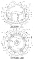
- FIG. 1 a perspective view of the burner tile 28 and the wall 34 thereof is shown.
- the interior sides of the wall 34 are vertical as best shown in FIG. 2.
- the exterior sides of the wall 34 are divided into a plurality of sections 36 and 38 by radially positioned baffles 40 with the alternate sections 36 and 38 having the same or different heights and slanting towards the opening 32 at the same or different angles.
- the alternating sections have different heights and slant at different angles as shown in the drawings.
- the sections 36 have short heights and slant towards the opening 32 in the burner tile 34 at large angles as compared to the sections 38 which have taller heights and slant toward the opening 32 at smaller angles.
- the sections 36 and 38 between the baffles 40 alternate around the wall 34.
- the alternating sections 36 have heights in the range of from about 0 inches to about 16 inches and slant towards the opening 32 at an angle in the range of from about 0 degrees to about 90 degrees.
- the alternating sections 38 can have the same or different heights as the alternating sections 36 in the range of from about 2 inches to about 16 inches and slant towards the opening 32 at the same or different angles in the range of from about 0 degrees to about 60 degrees.
- the alternating sections 36 have heights in the range of from about 0 inches to about 16 inches and slant in the range of from about 0 degrees to about 90 degrees and the alternating sections 38 have different heights in the range of from about 2 inches to about 16 inches and slant differently in the range of from about 0 degrees to about 60 degrees.
- the sections 36 each include a passageway 42 extending from the outside to the inside of the wall 34 through which fuel gas mixed with flue gases flow as will be described further hereinbelow.
- the first of the alternating sections have heights in the range of from about 5 inches to about 10 inches and slant towards the opening at an angle in the range of from about 10 degrees to about 30 degrees
- the second of the alternating sections have the same or different heights as the first of the alternating sections in the range of from about 6 inches to about 12 inches and slant towards the opening at the same or different angles in the range of from about 5 degrees to about 15 degrees.
- the first of the alternating sections have heights of about 7 inches and slant towards the opening at an angle of about 20 degrees, and the second of the alternating sections have heights of about 9 inches and slant towards the opening at an angle of about 10 degrees.
- a central primary fuel gas nozzle 44 can optionally be positioned within the opening 32 near the bottom of the burner tile 28.
- the nozzle 44 is connected by a conduit 46 to a fuel gas manifold 48.
- the conduit 46 is connected to the manifold 48 by a union 50 and a conduit 52 connected to the manifold 48 is connected to a source of pressurized fuel gas.
- a venturi 37 can optionally be positioned around and above the nozzle 44 so that a fuel gas lean mixture of fuel gas and air is formed and combusted in and above the venturi 37.
- the burner 14 can optionally include a plurality of nozzles 44 and venturis 37 in lieu of the single nozzle 44 and venturi 37.
- a plurality of secondary fuel gas discharge nozzles 54 are positioned in spaced relationship on the surface 30 of the burner tile 28 adjacent to the bottoms of the sections 36 and 38 of the wall 34.
- the nozzles 54 are positioned adjacent the intersections of the sections 36 and 38 with the surface of the base portion 30 of the burner tile 28.
- the nozzles 54 are connected to fuel gas conduits 56 (FIG. 2) which are connected to the fuel gas manifold 48 by unions 58.
- the nozzles 54 positioned adjacent to the sections 38 include fuel gas discharge openings therein whereby secondary fuel gas is discharged in fan shapes substantially parallel and adjacent to the exterior surfaces of the sections 38.
- the nozzles 54 positioned adjacent to the sections 36 include fuel gas discharge openings therein whereby secondary fuel gas is discharged in fan shapes substantially parallel and adjacent to the exterior surfaces of the sections 36. As the secondary fuel gas discharged by the nozzles 54 flows over the surfaces of the sections 36 and 38, flue gases in the furnace space outside the burner tile 28 are mixed with the secondary fuel gas.
- the passageways 42 in the sections 36 are positioned adjacent to the nozzles 54 as illustrated best in FIG. 3.
- the fuel gas nozzles 54 adjacent to the sections 36 and the passageways 42 formed therein include primary fuel gas discharge openings for discharging primary fuel gas into the interior of the opening 32 and the wall 34 of the burner tile 28. Because of the primary fuel gas jets flowing through the openings 42, furnace space flue gases outside of the burner tile 28 are drawn into and flow through the openings 42 with the primary fuel gas into the interior of the opening 32 and wall 34 of the burner tile 28.
- passageways 42 with primary fuel gas jets and flue gases flowing therethrough are preferably located in every other section as described above, it is to be understood that one or more passageways 42 with primary fuel gas jets and flue gases flowing therethrough can be utilized in the wall 34 of the burner tile 28.
- the baffles function to divide the secondary fuel gas and flue gases into a plurality of separate streams which enter and intimately mix with the primary fuel gas-flue gases-air mixtures discharged from within the wall 34 of the burner tile 28.
- the primary fuel gas-flue gases-air mixtures formed within the wall 34 are ignited while within the wall 34 and then flow out of the wall 34.
- the collisions of the secondary fuel gas-flue gases streams with the primary fuel gas-flue gases-air mixtures create a plurality of U-shaped or folded flames 60 as shown in FIG. 5.
- one of the primary mechanisms that produce NO x in a combustion process is thermal NO x , i.e., the higher the flame temperature, the more NO x that is created.
- the multiplicity of folded flames 60 shown in FIG. 5 allow the fuel gas to be rapidly mixed with flue gases prior to and during burning with air thereby reducing NO x .
- the increased surface area of the folded and convoluted flames 60 causes flue gases to mix with the flames more effectively, and the breaks 62 in the flames that exist between the folds allow flue gases to further penetrate between the flames and mix therewith, all of which contribute to very low NO x production.
- fuel gas is introduced into the furnace space to which the burner 10 is attached and burned therein at a flow rate which results in the desired heat release.
- Air is also introduced into the burner housing 14 and a column of the air flows into the furnace space.
- the flow rate of air introduced into the furnace space is in the range of from about 0% to about 100% in excess of the flow rate of air required to form a stoichiometric mixture of air and fuel gas.
- the flow rate of air is in excess of the stoichiometric flow rate of air by about 15%.
- the mixture of fuel gas and air discharged into the furnace space contains from about 0% to about 100% of excess air. As shown in FIG.
- the column of air flows through the housing 14 and through the opening 32 in the burner tile 28 into the mixing zone formed within the interior and above the wall 34. While within the mixing zone, the air mixes with the primary fuel gas and flue gases discharged into the mixing zone by way of the passageways 42 and the fuel gas nozzles 54 positioned adjacent to the passageways 42 and optionally by way of the fuel gas nozzle 44.
- the resulting primary fuel gas-flue gases-air mixture containing a large excess of air is burned within and adjacent to the top of the burner tile 28 and the flue gases formed therefrom have very low NO x content due to the dilution of the fuel gas by the excess air and flue gases.
- the secondary fuel gas discharged in directions parallel to the surfaces of the sections 36 and 38 by the nozzles 54 are mixed with flue gases surrounding the burner tile 28.
- the resulting secondary fuel gas-flue gases mixtures are discharged into the primary fuel gas-air mixture flowing from the interior of the wall 34 in a plurality of separate streams which form a folded flame pattern and mix with the primary fuel gas-air mixture to form a highly mixed fuel gas-flue gases-air mixture.
- the fuel gas-flue gases-air mixture bums in a multiplicity of folded flames in the furnace space and produces flue gases of low NO x content due to the fuel gas being diluted by relatively cool excess air and flue gases.
- the secondary fuel gas is preferably discharged by the nozzles 44 adjacent to the surfaces of all of the sections 36 and 38, it is to be understood that the secondary fuel gas can be discharged from one or more nozzles 44 adjacent to one or more of the sections 36 and 38.
- a method of this invention for discharging a mixture of fuel gas and air into a furnace space wherein the mixture is burned in a folded flame pattern and flue gases having low NO x content are formed therefrom is comprised of the steps of: (a) discharging the air into a mixing zone within and adjacent to a wall which extends into the furnace space and has exterior sides divided into alternating sections by a plurality of radially positioned baffles attached thereto, the alternating sections having the same or different heights and slanting towards the opening at the same or different angles and one or more of the alternating sections having a passageway formed therein for conducting a primary fuel gas and flue gases mixture from outside the section to within the wall; (b) discharging a primary portion of the fuel gas from locations outside the wall and adjacent to the one or more wall sections having passageways formed therein so that the primary portion of the fuel gas is mixed with flue gases in the furnace space and the resulting primary fuel gas-flue gases mixture formed flows into the mixing zone within the wall by way of said passageways to
- the above method can also include the optional step of introducing a portion of the primary fuel gas into the mixing zone within the wall of the burner tile whereby the primary fuel gas mixes with air therein.
- the fuel gas, flue gases and air discharged into the furnace space in accordance with step (b) can contain from about 0% to about 100% of excess air.
- the primary portion of fuel gas utilized in accordance with step (b) is in the range of from about 2% to about 40% by volume of the total fuel gas discharged into the furnace space and the secondary portion of fuel gas utilized in accordance with step (c) is in the range of from about 60% to about 98% by volume of the total fuel gas discharged into the furnace space.
- Another method of this invention for discharging a fuel gas and air mixture into a furnace space wherein the mixture is burned in a folded flame pattern and flue gases having low NO x content are formed therefrom is comprised of the following steps: (a) discharging a column of the air into the furnace space; (b) discharging a first portion of the fuel gas mixed with flue gases from the furnace space into the column of the air; and (c) discharging a second portion of the fuel gas mixed with flue gases from the furnace space into the column of air containing the first portion of the fuel gas mixed with flue gases in a plurality of separate streams from spaced locations around the column, the separate streams entering the column radially and burning therein along with the first portion of the fuel gas in separate folded flames surrounded by and mixed with flue gases and air.
- Yet another method of this invention for discharging a fuel gas and air mixture into a furnace space wherein the mixture is burned in a folded flame pattern and flue gases having low NO x content are formed therefrom is comprised of the following steps: (a) discharging said air into said furnace space; and (b) discharging said fuel gas mixed with flue gases from said furnace space into said air in two or more separate streams which enter the air and burn therein in one or more folded flames surrounded by and mixed with flue gases and air.
- a burner apparatus 10 designed for a heat release of 8,000,000 BTU per hour by burning natural gas having a caloric value of 913 BTU/SCF was fired into a furnace space.
- Pressurized fuel gas was supplied to the manifold 48 of the burner 10 at a pressure of about 33 psig and a flow rate of about 8765 SCF/hour.
- a 20% by volume portion of the fuel gas (1753 SCF/hour) was used as primary fuel gas and was discharged within the opening 32 and wall 34 of the burner tile 28 by the fuel gas discharge nozzle 44 and by the fuel gas discharge nozzles 54 positioned adjacent to the openings 42 in the wall 40 of the burner tile 28.
- the remaining portion of the fuel gas i.e., the secondary portion (at a rate of 7012 SCF/hour) was discharged into the furnace space by the nozzles 54 in separate fuel gas streams mixed with flue gases.
- the rate of air introduced into the furnace space by way of the air register 24, the housing 14 and the burner tile 28 was at least 15% in excess of the stoichiometric air rate relative to the total fuel gas rate.
- the primary fuel gas-flue gases air mixture began to burn at the vicinity of the passages 42 and at the top of the burner tile wall 34.
- the burner apparatus 10 Because of the dilution of the primary and secondary fuel gases with flue gases and excess air and the intimate mixing of the fuel gas-air-flue gases mixture, the burner had a high turn down ratio and produced very low NO x emissions. Finally, the burner apparatus 10 has compact dimensions (significantly smaller than other low NO x burners) and can be easily installed in existing furnaces.
- a three dimensional model of the furnace in which the burner apparatus was tested was then prepared and the burner model was mounted in the furnace model exactly like the test burner and furnace utilized in Example 1 except that the air entered the housing from the side instead of the bottom.
- the flow spaces in the burner model were divided into small volumes using the finite volume method and boundary conditions were applied, e.g., fuel pressure, flow rates, etc. at the entrances of the burner model.
- the software then calculated and predicted the flow patterns as well as combustion reactions and the resulting flame pattern by iteratively calculating values for all the combustion and flow parameters in each of the small volumes.
- the flame pattern includes eight folded flames 60 corresponding to the eight sections 36 and 38 of the burner tile having breaks 62 between the folds.
- the center flame 64 is produced by the burning of the fuel discharged from the fuel gas nozzle 44.
- the separate folded flames 60 allow the fuel gas to be rapidly mixed with flue gases prior to burning with air thereby reducing the flame temperature and production of NO x . Also, the increased surface of the folded flames 60 and the breaks 62 that exist between the folds allow flue gases to penetrate the flames and mix therewith to a greater degree than has heretofore been possible. Consequently, the NO x emissions content of the flue gases released to the atmosphere is very low.
Landscapes
- Engineering & Computer Science (AREA)
- Chemical & Material Sciences (AREA)
- Combustion & Propulsion (AREA)
- Mechanical Engineering (AREA)
- General Engineering & Computer Science (AREA)
- Gas Burners (AREA)
- Pre-Mixing And Non-Premixing Gas Burner (AREA)
Abstract
Description
Claims (31)
- A compact gas burner apparatus having a short flame length and a high turndown ratio for discharging a mixture of fuel gas and air into a furnace space wherein the mixture is burned and flue gases having low NOx content are formed therefrom comprising:a housing having an open end attached to said furnace space;means for introducing a controlled flow rate of said air into said housing attached thereto;a burner tile attached to the open end of said housing having an opening formed therein for allowing said air to flow therethrough and having a wall surrounding said opening which extends into said furnace space, the exterior sides of said wall being divided into sections by a plurality of radially positioned baffles attached thereto with alternate sections having different heights and slanting towards said opening at different angles and one or more of the alternating sections having a primary fuel gas passageway formed therein for conducting primary fuel gas from outside said section to within said wall; anda plurality of fuel gas nozzles connected to said source of fuel gas and positioned outside said wall of said burner tile for discharging secondary fuel gas adjacent to said external slanted wall sections with one or more of said fuel gas nozzles also discharging primary fuel gas mixed with flue gases into and through said primary fuel gas passageways whereby said secondary fuel gas mixes with flue gases in said furnace space, the mixture of secondary fuel gas and flue gases mixes with unburned air, primary fuel gas and flue gases flowing through said opening and wall of said burner tile, and the resultant mixture is burned in said furnace space.
- The burner apparatus of claim 1 wherein a first of said alternating wall sections has a short height and slants towards said opening in said burner tile at a large angle, the second of said wall sections has the same or a taller height and slants towards said opening at the same or a smaller angle and successive alternating sections have heights and angles which are the same as said first and second sections.
- A compact gas burner apparatus having a folded flame pattern, a short flame length and a high turndown ratio for discharging a mixture of fuel gas and air into a furnace space wherein the mixture is burned and flue gases having low NOx content are formed therefrom comprising:a housing having an open end attached to said furnace space;an air register for introducing a controlled flow rate of air into said housing attached thereto;a burner tile attached to the open end of said housing having an opening formed therein for allowing said air to flow therethrough and having a wall surrounding said opening which extends into said furnace space, the exterior sides of said wall being divided into sections by a plurality of radially positioned baffles attached thereto with alternate sections having the same or different heights and slanting towards said opening at the same or different angles, a first of said alternating wall sections having a short height and slanting towards said opening at a large angle, the second of said wall sections having the same or a taller height and slanting towards said opening at the same or a smaller angle and successive alternating sections having heights and angles which are the same as said first and second sections, every other of said slanted wall sections also having passageways formed therein for conducting primary fuel gas and flue gases into the interior of said wall; anda plurality of fuel gas nozzles connected to said source of fuel gas and positioned outside said wall of said burner tile for discharging secondary fuel gas adjacent to said external slanted wall sections whereby said secondary fuel gas mixes with flue gases in said furnace space and the resultant mixture mixes with unburned air, primary fuel gas and flue gases flowing through said opening and wall in said burner tile, and is burned in said furnace space, and a portion of said fuel gas nozzles discharging primary fuel gas mixed with flue gases through said every other passageway in said slanted wall sections into the interior of said burner tile wherein said primary fuel gas and flue gases mix with air therein.
- The burner apparatus of claim 1, 2 or 3, wherein said radially positioned baffles attached to said burner tile extend in directions parallel to the axis of said burner tile wall whereby said secondary fuel gas and flue gases are divided into a plurality of separate streams which mix with said primary fuel gas and unburned air flowing through said opening and wall of said burner tile.
- The burner apparatus of claim 2 or 3, wherein said first of said alternating sections have heights in the range of from about 0 inches to about 16 inches and slant towards said opening at an angle in the range of from about 0 degrees to about 90 degrees, and the second of said alternating sections have the same or different heights as the first of said alternating sections in the range of from about 2 inches to about 16 inches and slant towards said opening at the same or different angles in the range of from about 0 degrees to about 60 degrees.
- The burner apparatus of claim 2 or 3, wherein said first of said alternating sections have heights in the range of from about 5 inches to about 10 inches and slant towards said opening at an angle in the range of from about 10 degrees to about 30 degrees, and the second of said alternating sections have the same or different heights as the first of said alternating sections in the range of from about 6 inches to about 12 inches and slant towards said opening at the same or different angles in the range of from about 5 degrees to about 15 degrees.
- The burner apparatus of claim 2 or 3, wherein said first of said alternating sections have heights of about 7 inches and slant towards said opening at an angle of about 20 degrees, and the second of said alternating sections have heights of about 9 inches and slant towards said opening at an angle of about 10 degrees.
- The burner apparatus of any one of claims 2 to 7, wherein said passageways are located in said slanted wall sections which have short heights and slant towards said opening in said burner tile at large angles, said passageways being positioned whereby primary fuel gas discharged from said fuel gas nozzles mixes with flue gases and flows through said passageways into the interior of said wall of said burner tile wherein the mixture mixes with air.
- The burner apparatus of any one of the preceding claims, wherein said burner tile, said opening therein and the interior of said wall of said burner tile are substantially circular, rectangular, square, triangular, polygonal or other shape.
- The burner apparatus of any one of the preceding claims, wherein said open end of said housing is circular, square, triangular, polygonal or other shape and said housing is cylindrical, square, rectangular, triangular, polygonal or other shape.
- The burner apparatus of any one of the preceding claims, further comprising at least one primary fuel gas nozzle connected to a source of fuel gas positioned within said opening and wall of said burner tile for mixing additional primary fuel gas with said air flowing through said burner tile and discharging the mixture into said furnace space.
- The burner apparatus of claim 11, further comprising a venturi positioned around and above said additional primary fuel gas nozzle.
- The burner apparatus of any one of the preceding claims, further comprising a flame stabilizing surface within said opening of said burner tile.
- The burner apparatus of claim 4, wherein said separate streams of secondary fuel gas and flue gases mixed with said unburned air and primary fuel gas are burned in said furnace space in a folded flame pattern which produces flue gases having low NOx content.
- A method of discharging a mixture of fuel gas and air into a furnace space wherein said mixture is burned in a folded flame pattern and flue gases having low NOx content are formed therefrom comprising the steps of:(a) discharging said air into a mixing zone within and adjacent to a wall which extends into said furnace space and has exterior sides divided into alternating sections by a plurality of radially positioned baffles attached thereto, the alternating sections having the same or different heights and slanting towards said opening at the same or different angles and one or more of the alternating sections having a passageway formed therein for conducting a primary fuel gas and flue gases mixture from outside said section to within said wall;(b) discharging a primary portion of said fuel gas from locations outside said wall and adjacent to said one or more wall sections having passageways formed therein so that said primary portion of said fuel gas is mixed with flue gases in said furnace space and the resulting primary fuel gas-flue gases mixture formed flows into said mixing zone within said wall by way of said passageways to form a primary fuel gas-flue gases-air mixture which flows into said furnace space; and(c) discharging a secondary portion of said fuel gas from one or more locations outside said wall and adjacent to one or more of said wall sections so that said secondary portion of fuel gas mixes with flue gases in said furnace space and the secondary fuel gas-flue gases mixture formed is discharged into said primary fuel gas-flue gases-air mixture in one or more separate streams formed by said radially positioned baffles which enter and mix with said primary fuel gas-flue gases-air mixture to form a highly mixed fuel gas-flue gases-air mixture which burns in said folded flame pattern.
- The method of claim 15, wherein said mixture of fuel gas, flue gases and air discharged into said furnace space in accordance with step (b) contains from 0% to about 100% of excess air.
- The method of claim 15 or 16, wherein said primary portion of said fuel gas used to form said primary fuel gas-air mixture in accordance with step (b) is in the range of from about 2% to about 40% by volume of the total fuel gas discharged into said furnace space.
- The method of claim 15, 16 or 17, wherein said secondary portion of fuel gas used to form said secondary fuel gas-flue gases mixtures in accordance with step (c) is in the range of from about 60% to about 98% by volume of the total flue gas discharged into said furnace space.
- The method of claim 15, 16, 17 or 18, wherein said wall is formed of refractory material and is part of a refractory tile having an opening within said wall.
- The method of claim 19 wherein a first of said alternating wall sections has a short height and slants towards opening at a small angle, the second of said wall sections has a taller height and slants towards said opening at a larger angle and successive alternating sections have heights and angles which are the same as said first and second sections.
- A method of discharging a fuel gas and air mixture into a furnace space wherein said mixture is burned in a folded flame pattern and flue gases having low NOx content are formed therefrom comprising the steps of:(a) discharging a column of said air into said furnace space;(b) discharging a first portion of said fuel gas mixed with flue gases from said furnace space into said column of said air; and(c) discharging a second portion of said fuel gas mixed with flue gases from said furnace space into said column of air containing said first portion of fuel gas mixed with flue gases in a plurality of separate streams from spaced locations around said column, said separate streams entering said column radially and burning therein along with said first portion of said fuel gas in separate folded flames surrounded by and mixed with flue gases and air.
- The method of claim 21 wherein said separate streams of step (c) enter said column radially at an upward and inward angle.
- The method of claim 21 or 22, which optionally further comprises the step of ischarging a part of said first portion of said fuel gas into said column of air prior to step (a).
- The method of claim 21, 22 or 23, wherein said mixture of fuel gas and air discharged into said furnace space contains from 0% to about 100% of excess air.
- The method of claim 21, 22, 23 or 24, wherein said first portion of said fuel gas is in the range of from about 2% to about 40% by volume of the total fuel gas discharged into said column of air.
- The method of claim any one of claims 21 to 25, wherein said second portion of said fuel gas is in the range of from about 60% to about 98% by volume of the total fuel gas discharged into said column of air and fuel gas.
- A method of discharging a fuel gas and air mixture into a furnace space wherein said mixture is burned in a folded flame pattern and flue gases having low NOx content are formed therefrom comprising the steps of:(a) discharging said air into said furnace space; and(b) discharging said fuel gas from said furnace space into said air in two or more separate streams which enter the air and burn therein in one or more folded flames surrounded by and mixed with flue gases and air.
- The method of claim 27, wherein said separate streams of step (b) enter said air radially.
- The method of claim 27 or 28, wherein said mixture of fuel gas and air discharged into said furnace space contains from 0% to about 100% of excess air.
- The method of claim 27, 28 or 29, wherein said fuel gas in said first stream is in the range of from about 2% to about 40% by volume of the total fuel gas discharged into said column of air.
- The method of claim 27, 28, 29 or 30, wherein said fuel gas in said second stream is in the range of from about 60% to about 98% by volume of the total fuel gas discharged into said column of air and fuel gas.
Applications Claiming Priority (2)
| Application Number | Priority Date | Filing Date | Title |
|---|---|---|---|
| US313065 | 2002-12-06 | ||
| US10/313,065 US6695609B1 (en) | 2002-12-06 | 2002-12-06 | Compact low NOx gas burner apparatus and methods |
Publications (4)
| Publication Number | Publication Date |
|---|---|
| EP1426681A2 true EP1426681A2 (en) | 2004-06-09 |
| EP1426681A3 EP1426681A3 (en) | 2004-08-04 |
| EP1426681B1 EP1426681B1 (en) | 2005-08-31 |
| EP1426681B9 EP1426681B9 (en) | 2007-12-26 |
Family
ID=31495551
Family Applications (1)
| Application Number | Title | Priority Date | Filing Date |
|---|---|---|---|
| EP03253635A Expired - Lifetime EP1426681B9 (en) | 2002-12-06 | 2003-06-09 | Compact low NOx gas burner apparatus and methods |
Country Status (14)
| Country | Link |
|---|---|
| US (2) | US6695609B1 (en) |
| EP (1) | EP1426681B9 (en) |
| JP (1) | JP4177185B2 (en) |
| KR (1) | KR100892460B1 (en) |
| CN (1) | CN1229589C (en) |
| AR (1) | AR036971A1 (en) |
| AT (1) | ATE303559T1 (en) |
| BR (1) | BR0302335B1 (en) |
| CA (1) | CA2429478C (en) |
| DE (2) | DE60301475D1 (en) |
| ES (1) | ES2243863T3 (en) |
| MX (1) | MXPA03005762A (en) |
| SA (2) | SA03240346B1 (en) |
| TW (1) | TWI304872B (en) |
Cited By (2)
| Publication number | Priority date | Publication date | Assignee | Title |
|---|---|---|---|---|
| WO2013071048A2 (en) | 2011-11-10 | 2013-05-16 | Zeeco, Inc. | Low nox burner apparatus and method |
| US20240263778A1 (en) * | 2023-02-06 | 2024-08-08 | Weil-Mclain | Burner access hatch |
Families Citing this family (37)
| Publication number | Priority date | Publication date | Assignee | Title |
|---|---|---|---|---|
| US6875008B1 (en) * | 2003-01-29 | 2005-04-05 | Callidus Technologies, L.L.C. | Lean pre-mix low NOx burner |
| US8794960B2 (en) * | 2004-02-25 | 2014-08-05 | John Zink Company, Llc | Low NOx burner |
| US7670135B1 (en) | 2005-07-13 | 2010-03-02 | Zeeco, Inc. | Burner and method for induction of flue gas |
| US20070269755A2 (en) * | 2006-01-05 | 2007-11-22 | Petro-Chem Development Co., Inc. | Systems, apparatus and method for flameless combustion absent catalyst or high temperature oxidants |
| US7878798B2 (en) * | 2006-06-14 | 2011-02-01 | John Zink Company, Llc | Coanda gas burner apparatus and methods |
| US7632090B2 (en) | 2007-10-30 | 2009-12-15 | Air Products And Chemicals, Inc. | Burner system and method of operating a burner for reduced NOx emissions |
| US7775791B2 (en) | 2008-02-25 | 2010-08-17 | General Electric Company | Method and apparatus for staged combustion of air and fuel |
| CN102224378B (en) * | 2008-09-22 | 2014-07-23 | 达塞尔·卡尔灵顿 | burner |
| EP2218965A1 (en) | 2009-02-16 | 2010-08-18 | Total Petrochemicals Research Feluy | Low NOx burner |
| US20110085030A1 (en) | 2009-10-07 | 2011-04-14 | John Zink Company, Llc | Image sensing system, software, apparatus and method for controlling combustion equipment |
| JP2011169570A (en) * | 2010-02-22 | 2011-09-01 | Jfe Steel Corp | Sintering machine |
| KR200454114Y1 (en) * | 2010-07-08 | 2011-06-16 | 진점남 | Indicator for point display |
| US9134024B2 (en) * | 2012-07-19 | 2015-09-15 | John Zink Company, Llc | Radial burner air inlet with linear volumetric air control |
| US10571124B2 (en) | 2013-02-14 | 2020-02-25 | Clearsign Combustion Corporation | Selectable dilution low NOx burner |
| US10125983B2 (en) | 2013-02-14 | 2018-11-13 | Clearsign Combustion Corporation | High output porous tile burner |
| US10386062B2 (en) | 2013-02-14 | 2019-08-20 | Clearsign Combustion Corporation | Method for operating a combustion system including a perforated flame holder |
| US11460188B2 (en) | 2013-02-14 | 2022-10-04 | Clearsign Technologies Corporation | Ultra low emissions firetube boiler burner |
| WO2014127311A1 (en) | 2013-02-14 | 2014-08-21 | Clearsign Combustion Corporation | Fuel combustion system with a perforated reaction holder |
| EP2956718A4 (en) | 2013-02-14 | 2016-11-30 | Clearsign Comb Corp | Perforated flame holder and burner including a perforated flame holder |
| US10119704B2 (en) | 2013-02-14 | 2018-11-06 | Clearsign Combustion Corporation | Burner system including a non-planar perforated flame holder |
| JP6168875B2 (en) * | 2013-06-21 | 2017-07-26 | 日本ファーネス株式会社 | Fuel two-stage combustion burner apparatus and fuel two-stage combustion method |
| EP2821699A1 (en) * | 2013-07-02 | 2015-01-07 | Haldor Topsøe A/S | Mixing of recycle gas with fuel gas to a burner |
| CN105556210B (en) * | 2013-09-23 | 2018-07-24 | 克利尔赛恩燃烧公司 | For low NOXThe porous flame holder of burning |
| US9593847B1 (en) | 2014-03-05 | 2017-03-14 | Zeeco, Inc. | Fuel-flexible burner apparatus and method for fired heaters |
| US9593848B2 (en) | 2014-06-09 | 2017-03-14 | Zeeco, Inc. | Non-symmetrical low NOx burner apparatus and method |
| EP3161380B1 (en) | 2014-06-30 | 2019-02-06 | Tubitak | A hybrid homogenous-catalytic combustion system |
| EP3006826B1 (en) * | 2014-10-10 | 2017-05-03 | WORGAS BRUCIATORI S.r.l. | Burner |
| CN104613474A (en) * | 2015-02-05 | 2015-05-13 | 湖南吉祥石化科技股份有限公司 | Bottom-mounted type NOx discharging circular flame gas burner |
| US20170198902A1 (en) * | 2016-01-08 | 2017-07-13 | Zeeco, Inc. | LOW NOx BURNER APPARATUS AND METHOD |
| CN105694931B (en) * | 2016-03-21 | 2018-11-13 | 陈明海 | A kind of biomass carbonizing furnace with curved shape asymmetric burner |
| JP6433965B2 (en) * | 2016-11-29 | 2018-12-05 | ボルカノ株式会社 | Combustion device |
| US10982846B2 (en) * | 2017-06-14 | 2021-04-20 | Webster Combustion Technology Llc | Vortex recirculating combustion burner head |
| EP4227579A1 (en) * | 2017-09-05 | 2023-08-16 | John Zink Company, LLC | Low nox and co combustion burner apparatus |
| EP3688373B1 (en) * | 2017-09-25 | 2024-12-11 | Beijing Zhongyu Topsun Energy Technology Co., Ltd. | Burner |
| CN111386428B (en) * | 2017-11-20 | 2022-11-01 | 约翰·尊科股份有限公司 | Radiant wall burner |
| CN108266727B (en) * | 2018-02-12 | 2024-04-02 | 岳阳恒盛石化科技有限公司 | Ultra-low NO of internal circulation of flue gas x Exhaust gas burner |
| CA3046916C (en) * | 2018-06-18 | 2022-08-09 | Emission Rx Ltd. | Waste gas combustor with secondary air control and liquid containment/vaporization chamber |
Family Cites Families (31)
| Publication number | Priority date | Publication date | Assignee | Title |
|---|---|---|---|---|
| US2918117A (en) * | 1956-10-04 | 1959-12-22 | Petro Chem Process Company Inc | Heavy fuel burner with combustion gas recirculating means |
| US4004875A (en) * | 1975-01-23 | 1977-01-25 | John Zink Company | Low nox burner |
| US5073105A (en) * | 1991-05-01 | 1991-12-17 | Callidus Technologies Inc. | Low NOx burner assemblies |
| US5284438A (en) | 1992-01-07 | 1994-02-08 | Koch Engineering Company, Inc. | Multiple purpose burner process and apparatus |
| US5238395A (en) | 1992-03-27 | 1993-08-24 | John Zink Company | Low nox gas burner apparatus and methods |
| US5195884A (en) | 1992-03-27 | 1993-03-23 | John Zink Company, A Division Of Koch Engineering Company, Inc. | Low NOx formation burner apparatus and methods |
| US5545161A (en) * | 1992-12-01 | 1996-08-13 | Cardiac Pathways Corporation | Catheter for RF ablation having cooled electrode with electrically insulated sleeve |
| US5348554A (en) * | 1992-12-01 | 1994-09-20 | Cardiac Pathways Corporation | Catheter for RF ablation with cooled electrode |
| US5470224A (en) | 1993-07-16 | 1995-11-28 | Radian Corporation | Apparatus and method for reducing NOx , CO and hydrocarbon emissions when burning gaseous fuels |
| US5407347A (en) | 1993-07-16 | 1995-04-18 | Radian Corporation | Apparatus and method for reducing NOx, CO and hydrocarbon emissions when burning gaseous fuels |
| US5487757A (en) * | 1993-07-20 | 1996-01-30 | Medtronic Cardiorhythm | Multicurve deflectable catheter |
| US5545200A (en) * | 1993-07-20 | 1996-08-13 | Medtronic Cardiorhythm | Steerable electrophysiology catheter |
| DE69433213T2 (en) * | 1993-11-10 | 2004-05-06 | Medtronic, Inc., Minneapolis | Catheter with electrode arrangement |
| US5542840A (en) * | 1994-01-26 | 1996-08-06 | Zeeco Inc. | Burner for combusting gas and/or liquid fuel with low NOx production |
| US5458481A (en) * | 1994-01-26 | 1995-10-17 | Zeeco, Inc. | Burner for combusting gas with low NOx production |
| US5882346A (en) * | 1996-07-15 | 1999-03-16 | Cardiac Pathways Corporation | Shapable catheter using exchangeable core and method of use |
| US5826576A (en) * | 1996-08-08 | 1998-10-27 | Medtronic, Inc. | Electrophysiology catheter with multifunction wire and method for making |
| US5785706A (en) * | 1996-11-18 | 1998-07-28 | Daig Corporation | Nonsurgical mapping and treatment of cardiac arrhythmia using a catheter contained within a guiding introducer containing openings |
| US5906605A (en) * | 1997-01-10 | 1999-05-25 | Cardiac Pathways Corporation | Torquable guiding catheter for basket deployment and method |
| US6251109B1 (en) * | 1997-06-27 | 2001-06-26 | Daig Corporation | Process and device for the treatment of atrial arrhythmia |
| US6080151A (en) * | 1997-07-21 | 2000-06-27 | Daig Corporation | Ablation catheter |
| US6120500A (en) * | 1997-11-12 | 2000-09-19 | Daig Corporation | Rail catheter ablation and mapping system |
| US5899681A (en) | 1997-12-05 | 1999-05-04 | General Electric Company | Atmospheric gas burner assembly for improved flame retention and stability |
| US5984665A (en) * | 1998-02-09 | 1999-11-16 | Gas Research Institute | Low emissions surface combustion pilot and flame holder |
| US5993193A (en) * | 1998-02-09 | 1999-11-30 | Gas Research, Inc. | Variable heat flux low emissions burner |
| US6007325A (en) * | 1998-02-09 | 1999-12-28 | Gas Research Institute | Ultra low emissions burner |
| US6394792B1 (en) * | 1999-03-11 | 2002-05-28 | Zeeco, Inc. | Low NoX burner apparatus |
| US6325797B1 (en) * | 1999-04-05 | 2001-12-04 | Medtronic, Inc. | Ablation catheter and method for isolating a pulmonary vein |
| US6499990B1 (en) * | 2001-03-07 | 2002-12-31 | Zeeco, Inc. | Low NOx burner apparatus and method |
| US6565361B2 (en) | 2001-06-25 | 2003-05-20 | John Zink Company, Llc | Methods and apparatus for burning fuel with low NOx formation |
| US6672858B1 (en) * | 2001-07-18 | 2004-01-06 | Charles E. Benson | Method and apparatus for heating a furnace |
-
2002
- 2002-12-06 US US10/313,065 patent/US6695609B1/en not_active Expired - Lifetime
-
2003
- 2003-05-23 CA CA002429478A patent/CA2429478C/en not_active Expired - Lifetime
- 2003-06-09 ES ES03253635T patent/ES2243863T3/en not_active Expired - Lifetime
- 2003-06-09 DE DE60301475A patent/DE60301475D1/en not_active Expired - Lifetime
- 2003-06-09 AT AT03253635T patent/ATE303559T1/en not_active IP Right Cessation
- 2003-06-09 EP EP03253635A patent/EP1426681B9/en not_active Expired - Lifetime
- 2003-06-09 DE DE60301475T patent/DE60301475T4/en not_active Expired - Lifetime
- 2003-06-20 AR ARP030102212A patent/AR036971A1/en active IP Right Grant
- 2003-06-24 MX MXPA03005762A patent/MXPA03005762A/en active IP Right Grant
- 2003-06-27 KR KR1020030042543A patent/KR100892460B1/en not_active Expired - Fee Related
- 2003-06-30 TW TW092117886A patent/TWI304872B/en not_active IP Right Cessation
- 2003-06-30 BR BRPI0302335-4A patent/BR0302335B1/en active IP Right Grant
- 2003-07-01 JP JP2003189491A patent/JP4177185B2/en not_active Expired - Lifetime
- 2003-07-01 CN CNB031457371A patent/CN1229589C/en not_active Expired - Lifetime
- 2003-10-15 SA SA03240346A patent/SA03240346B1/en unknown
- 2003-10-15 SA SA07280048A patent/SA07280048B1/en unknown
-
2004
- 2004-02-10 US US10/775,978 patent/US7244119B2/en not_active Expired - Lifetime
Cited By (3)
| Publication number | Priority date | Publication date | Assignee | Title |
|---|---|---|---|---|
| WO2013071048A2 (en) | 2011-11-10 | 2013-05-16 | Zeeco, Inc. | Low nox burner apparatus and method |
| EP2780634A4 (en) * | 2011-11-10 | 2016-06-22 | Zeeco Inc | LOW NOX EMISSION BURNER APPARATUS AND METHOD |
| US20240263778A1 (en) * | 2023-02-06 | 2024-08-08 | Weil-Mclain | Burner access hatch |
Also Published As
| Publication number | Publication date |
|---|---|
| AR036971A1 (en) | 2004-10-20 |
| CN1229589C (en) | 2005-11-30 |
| ATE303559T1 (en) | 2005-09-15 |
| JP4177185B2 (en) | 2008-11-05 |
| SA03240346B1 (en) | 2007-08-13 |
| KR20040049776A (en) | 2004-06-12 |
| KR100892460B1 (en) | 2009-04-10 |
| US20040197719A1 (en) | 2004-10-07 |
| JP2004191032A (en) | 2004-07-08 |
| CN1506609A (en) | 2004-06-23 |
| SA07280048B1 (en) | 2011-06-14 |
| DE60301475T2 (en) | 2006-06-14 |
| TWI304872B (en) | 2009-01-01 |
| BR0302335B1 (en) | 2011-08-23 |
| EP1426681B9 (en) | 2007-12-26 |
| EP1426681A3 (en) | 2004-08-04 |
| DE60301475T4 (en) | 2008-03-20 |
| BR0302335A (en) | 2004-08-17 |
| DE60301475D1 (en) | 2005-10-06 |
| CA2429478C (en) | 2008-07-08 |
| US6695609B1 (en) | 2004-02-24 |
| ES2243863T3 (en) | 2005-12-01 |
| EP1426681B1 (en) | 2005-08-31 |
| CA2429478A1 (en) | 2004-06-06 |
| US7244119B2 (en) | 2007-07-17 |
| TW200409885A (en) | 2004-06-16 |
| MXPA03005762A (en) | 2005-10-18 |
Similar Documents
| Publication | Publication Date | Title |
|---|---|---|
| US6695609B1 (en) | Compact low NOx gas burner apparatus and methods | |
| US5275552A (en) | Low NOx gas burner apparatus and methods | |
| US5195884A (en) | Low NOx formation burner apparatus and methods | |
| US5344307A (en) | Methods and apparatus for burning fuel with low Nox formation | |
| US6565361B2 (en) | Methods and apparatus for burning fuel with low NOx formation | |
| US5154596A (en) | Methods and apparatus for burning fuel with low NOx formation | |
| US7198482B2 (en) | Compact low NOx gas burner apparatus and methods | |
| JP4540263B2 (en) | Low nitrogen oxide apparatus and method for burning liquid and gaseous fuels. | |
| CN101135442B (en) | Coanda gas burner apparatus and method | |
| US5980243A (en) | Flat flame | |
| US5269678A (en) | Methods and apparatus for burning fuel with low NOx formation | |
| EP0076036B1 (en) | Method and apparatus for burning fuel in stages | |
| JP4566011B2 (en) | Structure and method of remote staged radiant wall furnace burner. | |
| JP4673554B2 (en) | Removable ignition chamber filling used for burner | |
| EP1580484A2 (en) | Remote staged furnace burner configurations and methods | |
| JP4264005B2 (en) | NOx low emission burner with high fuel gas recirculation rate |
Legal Events
| Date | Code | Title | Description |
|---|---|---|---|
| PUAI | Public reference made under article 153(3) epc to a published international application that has entered the european phase |
Free format text: ORIGINAL CODE: 0009012 |
|
| AK | Designated contracting states |
Kind code of ref document: A2 Designated state(s): AT BE BG CH CY CZ DE DK EE ES FI FR GB GR HU IE IT LI LU MC NL PT RO SE SI SK TR |
|
| AX | Request for extension of the european patent |
Extension state: AL LT LV MK |
|
| PUAL | Search report despatched |
Free format text: ORIGINAL CODE: 0009013 |
|
| AK | Designated contracting states |
Kind code of ref document: A3 Designated state(s): AT BE BG CH CY CZ DE DK EE ES FI FR GB GR HU IE IT LI LU MC NL PT RO SE SI SK TR |
|
| AX | Request for extension of the european patent |
Extension state: AL LT LV MK |
|
| 17P | Request for examination filed |
Effective date: 20040915 |
|
| 17Q | First examination report despatched |
Effective date: 20041108 |
|
| GRAP | Despatch of communication of intention to grant a patent |
Free format text: ORIGINAL CODE: EPIDOSNIGR1 |
|
| AKX | Designation fees paid |
Designated state(s): AT BE BG CH CY CZ DE DK EE ES FI FR GB GR HU IE IT LI LU MC NL PT RO SE SI SK TR |
|
| GRAS | Grant fee paid |
Free format text: ORIGINAL CODE: EPIDOSNIGR3 |
|
| GRAA | (expected) grant |
Free format text: ORIGINAL CODE: 0009210 |
|
| AK | Designated contracting states |
Kind code of ref document: B1 Designated state(s): AT BE BG CH CY CZ DE DK EE ES FI FR GB GR HU IE IT LI LU MC NL PT RO SE SI SK TR |
|
| PG25 | Lapsed in a contracting state [announced via postgrant information from national office to epo] |
Ref country code: SK Free format text: LAPSE BECAUSE OF FAILURE TO SUBMIT A TRANSLATION OF THE DESCRIPTION OR TO PAY THE FEE WITHIN THE PRESCRIBED TIME-LIMIT Effective date: 20050831 Ref country code: FI Free format text: LAPSE BECAUSE OF FAILURE TO SUBMIT A TRANSLATION OF THE DESCRIPTION OR TO PAY THE FEE WITHIN THE PRESCRIBED TIME-LIMIT Effective date: 20050831 Ref country code: SI Free format text: LAPSE BECAUSE OF FAILURE TO SUBMIT A TRANSLATION OF THE DESCRIPTION OR TO PAY THE FEE WITHIN THE PRESCRIBED TIME-LIMIT Effective date: 20050831 Ref country code: AT Free format text: LAPSE BECAUSE OF FAILURE TO SUBMIT A TRANSLATION OF THE DESCRIPTION OR TO PAY THE FEE WITHIN THE PRESCRIBED TIME-LIMIT Effective date: 20050831 Ref country code: RO Free format text: LAPSE BECAUSE OF FAILURE TO SUBMIT A TRANSLATION OF THE DESCRIPTION OR TO PAY THE FEE WITHIN THE PRESCRIBED TIME-LIMIT Effective date: 20050831 |
|
| REG | Reference to a national code |
Ref country code: GB Ref legal event code: FG4D Ref country code: CH Ref legal event code: EP |
|
| REG | Reference to a national code |
Ref country code: IE Ref legal event code: FG4D |
|
| REF | Corresponds to: |
Ref document number: 60301475 Country of ref document: DE Date of ref document: 20051006 Kind code of ref document: P |
|
| PG25 | Lapsed in a contracting state [announced via postgrant information from national office to epo] |
Ref country code: DK Free format text: LAPSE BECAUSE OF FAILURE TO SUBMIT A TRANSLATION OF THE DESCRIPTION OR TO PAY THE FEE WITHIN THE PRESCRIBED TIME-LIMIT Effective date: 20051130 Ref country code: BG Free format text: LAPSE BECAUSE OF FAILURE TO SUBMIT A TRANSLATION OF THE DESCRIPTION OR TO PAY THE FEE WITHIN THE PRESCRIBED TIME-LIMIT Effective date: 20051130 Ref country code: SE Free format text: LAPSE BECAUSE OF FAILURE TO SUBMIT A TRANSLATION OF THE DESCRIPTION OR TO PAY THE FEE WITHIN THE PRESCRIBED TIME-LIMIT Effective date: 20051130 Ref country code: GR Free format text: LAPSE BECAUSE OF FAILURE TO SUBMIT A TRANSLATION OF THE DESCRIPTION OR TO PAY THE FEE WITHIN THE PRESCRIBED TIME-LIMIT Effective date: 20051130 |
|
| REG | Reference to a national code |
Ref country code: CH Ref legal event code: NV Representative=s name: R. A. EGLI & CO. PATENTANWAELTE |
|
| REG | Reference to a national code |
Ref country code: ES Ref legal event code: FG2A Ref document number: 2243863 Country of ref document: ES Kind code of ref document: T3 |
|
| PG25 | Lapsed in a contracting state [announced via postgrant information from national office to epo] |
Ref country code: PT Free format text: LAPSE BECAUSE OF FAILURE TO SUBMIT A TRANSLATION OF THE DESCRIPTION OR TO PAY THE FEE WITHIN THE PRESCRIBED TIME-LIMIT Effective date: 20060222 |
|
| PG25 | Lapsed in a contracting state [announced via postgrant information from national office to epo] |
Ref country code: HU Free format text: LAPSE BECAUSE OF FAILURE TO SUBMIT A TRANSLATION OF THE DESCRIPTION OR TO PAY THE FEE WITHIN THE PRESCRIBED TIME-LIMIT Effective date: 20060301 |
|
| ET | Fr: translation filed | ||
| PG25 | Lapsed in a contracting state [announced via postgrant information from national office to epo] |
Ref country code: IE Free format text: LAPSE BECAUSE OF NON-PAYMENT OF DUE FEES Effective date: 20060609 |
|
| PG25 | Lapsed in a contracting state [announced via postgrant information from national office to epo] |
Ref country code: MC Free format text: LAPSE BECAUSE OF NON-PAYMENT OF DUE FEES Effective date: 20060630 |
|
| PLBE | No opposition filed within time limit |
Free format text: ORIGINAL CODE: 0009261 |
|
| STAA | Information on the status of an ep patent application or granted ep patent |
Free format text: STATUS: NO OPPOSITION FILED WITHIN TIME LIMIT |
|
| 26N | No opposition filed |
Effective date: 20060601 |
|
| REG | Reference to a national code |
Ref country code: IE Ref legal event code: MM4A |
|
| REG | Reference to a national code |
Ref country code: GB Ref legal event code: 711B |
|
| NLR4 | Nl: receipt of corrected translation in the netherlands language at the initiative of the proprietor of the patent | ||
| REG | Reference to a national code |
Ref country code: GB Ref legal event code: 711F |
|
| PG25 | Lapsed in a contracting state [announced via postgrant information from national office to epo] |
Ref country code: EE Free format text: LAPSE BECAUSE OF FAILURE TO SUBMIT A TRANSLATION OF THE DESCRIPTION OR TO PAY THE FEE WITHIN THE PRESCRIBED TIME-LIMIT Effective date: 20050831 |
|
| PG25 | Lapsed in a contracting state [announced via postgrant information from national office to epo] |
Ref country code: LU Free format text: LAPSE BECAUSE OF NON-PAYMENT OF DUE FEES Effective date: 20060609 Ref country code: TR Free format text: LAPSE BECAUSE OF FAILURE TO SUBMIT A TRANSLATION OF THE DESCRIPTION OR TO PAY THE FEE WITHIN THE PRESCRIBED TIME-LIMIT Effective date: 20050831 |
|
| PG25 | Lapsed in a contracting state [announced via postgrant information from national office to epo] |
Ref country code: CY Free format text: LAPSE BECAUSE OF FAILURE TO SUBMIT A TRANSLATION OF THE DESCRIPTION OR TO PAY THE FEE WITHIN THE PRESCRIBED TIME-LIMIT Effective date: 20050831 |
|
| PGFP | Annual fee paid to national office [announced via postgrant information from national office to epo] |
Ref country code: CH Payment date: 20120612 Year of fee payment: 10 |
|
| REG | Reference to a national code |
Ref country code: CH Ref legal event code: PL |
|
| PG25 | Lapsed in a contracting state [announced via postgrant information from national office to epo] |
Ref country code: LI Free format text: LAPSE BECAUSE OF NON-PAYMENT OF DUE FEES Effective date: 20130630 Ref country code: CH Free format text: LAPSE BECAUSE OF NON-PAYMENT OF DUE FEES Effective date: 20130630 |
|
| REG | Reference to a national code |
Ref country code: FR Ref legal event code: PLFP Year of fee payment: 14 |
|
| PGFP | Annual fee paid to national office [announced via postgrant information from national office to epo] |
Ref country code: ES Payment date: 20160510 Year of fee payment: 14 |
|
| REG | Reference to a national code |
Ref country code: FR Ref legal event code: PLFP Year of fee payment: 15 |
|
| REG | Reference to a national code |
Ref country code: FR Ref legal event code: PLFP Year of fee payment: 16 |
|
| REG | Reference to a national code |
Ref country code: ES Ref legal event code: FD2A Effective date: 20181112 |
|
| PG25 | Lapsed in a contracting state [announced via postgrant information from national office to epo] |
Ref country code: ES Free format text: LAPSE BECAUSE OF NON-PAYMENT OF DUE FEES Effective date: 20170610 |
|
| PG25 | Lapsed in a contracting state [announced via postgrant information from national office to epo] |
Ref country code: CZ Free format text: LAPSE BECAUSE OF NON-PAYMENT OF DUE FEES Effective date: 20200609 |
|
| PGFP | Annual fee paid to national office [announced via postgrant information from national office to epo] |
Ref country code: BE Payment date: 20210518 Year of fee payment: 19 |
|
| PGFP | Annual fee paid to national office [announced via postgrant information from national office to epo] |
Ref country code: NL Payment date: 20220420 Year of fee payment: 20 |
|
| PGFP | Annual fee paid to national office [announced via postgrant information from national office to epo] |
Ref country code: IT Payment date: 20220510 Year of fee payment: 20 Ref country code: GB Payment date: 20220425 Year of fee payment: 20 Ref country code: FR Payment date: 20220408 Year of fee payment: 20 Ref country code: DE Payment date: 20220414 Year of fee payment: 20 |
|
| REG | Reference to a national code |
Ref country code: BE Ref legal event code: MM Effective date: 20220630 |
|
| PG25 | Lapsed in a contracting state [announced via postgrant information from national office to epo] |
Ref country code: BE Free format text: LAPSE BECAUSE OF NON-PAYMENT OF DUE FEES Effective date: 20220630 |
|
| REG | Reference to a national code |
Ref country code: DE Ref legal event code: R071 Ref document number: 60301475 Country of ref document: DE |
|
| REG | Reference to a national code |
Ref country code: NL Ref legal event code: MK Effective date: 20230608 |
|
| REG | Reference to a national code |
Ref country code: GB Ref legal event code: PE20 Expiry date: 20230608 |
|
| P01 | Opt-out of the competence of the unified patent court (upc) registered |
Effective date: 20230528 |
|
| PG25 | Lapsed in a contracting state [announced via postgrant information from national office to epo] |
Ref country code: GB Free format text: LAPSE BECAUSE OF EXPIRATION OF PROTECTION Effective date: 20230608 |