EP1426660A1 - Ball screw device - Google Patents
Ball screw device Download PDFInfo
- Publication number
- EP1426660A1 EP1426660A1 EP02767945A EP02767945A EP1426660A1 EP 1426660 A1 EP1426660 A1 EP 1426660A1 EP 02767945 A EP02767945 A EP 02767945A EP 02767945 A EP02767945 A EP 02767945A EP 1426660 A1 EP1426660 A1 EP 1426660A1
- Authority
- EP
- European Patent Office
- Prior art keywords
- balls
- screw shaft
- ball circulation
- ball
- grooves
- Prior art date
- Legal status (The legal status is an assumption and is not a legal conclusion. Google has not performed a legal analysis and makes no representation as to the accuracy of the status listed.)
- Granted
Links
Images









Classifications
-
- F—MECHANICAL ENGINEERING; LIGHTING; HEATING; WEAPONS; BLASTING
- F16—ENGINEERING ELEMENTS AND UNITS; GENERAL MEASURES FOR PRODUCING AND MAINTAINING EFFECTIVE FUNCTIONING OF MACHINES OR INSTALLATIONS; THERMAL INSULATION IN GENERAL
- F16H—GEARING
- F16H25/00—Gearings comprising primarily only cams, cam-followers and screw-and-nut mechanisms
- F16H25/18—Gearings comprising primarily only cams, cam-followers and screw-and-nut mechanisms for conveying or interconverting oscillating or reciprocating motions
- F16H25/20—Screw mechanisms
- F16H25/22—Screw mechanisms with balls, rollers, or similar members between the co-operating parts; Elements essential to the use of such members
-
- F—MECHANICAL ENGINEERING; LIGHTING; HEATING; WEAPONS; BLASTING
- F16—ENGINEERING ELEMENTS AND UNITS; GENERAL MEASURES FOR PRODUCING AND MAINTAINING EFFECTIVE FUNCTIONING OF MACHINES OR INSTALLATIONS; THERMAL INSULATION IN GENERAL
- F16H—GEARING
- F16H25/00—Gearings comprising primarily only cams, cam-followers and screw-and-nut mechanisms
- F16H25/18—Gearings comprising primarily only cams, cam-followers and screw-and-nut mechanisms for conveying or interconverting oscillating or reciprocating motions
- F16H25/20—Screw mechanisms
- F16H25/22—Screw mechanisms with balls, rollers, or similar members between the co-operating parts; Elements essential to the use of such members
- F16H25/2204—Screw mechanisms with balls, rollers, or similar members between the co-operating parts; Elements essential to the use of such members with balls
- F16H25/2233—Screw mechanisms with balls, rollers, or similar members between the co-operating parts; Elements essential to the use of such members with balls with cages or means to hold the balls in position
-
- F—MECHANICAL ENGINEERING; LIGHTING; HEATING; WEAPONS; BLASTING
- F16—ENGINEERING ELEMENTS AND UNITS; GENERAL MEASURES FOR PRODUCING AND MAINTAINING EFFECTIVE FUNCTIONING OF MACHINES OR INSTALLATIONS; THERMAL INSULATION IN GENERAL
- F16H—GEARING
- F16H25/00—Gearings comprising primarily only cams, cam-followers and screw-and-nut mechanisms
- F16H25/18—Gearings comprising primarily only cams, cam-followers and screw-and-nut mechanisms for conveying or interconverting oscillating or reciprocating motions
- F16H25/20—Screw mechanisms
- F16H25/22—Screw mechanisms with balls, rollers, or similar members between the co-operating parts; Elements essential to the use of such members
- F16H25/2204—Screw mechanisms with balls, rollers, or similar members between the co-operating parts; Elements essential to the use of such members with balls
- F16H25/2214—Screw mechanisms with balls, rollers, or similar members between the co-operating parts; Elements essential to the use of such members with balls with elements for guiding the circulating balls
- F16H25/2228—Screw mechanisms with balls, rollers, or similar members between the co-operating parts; Elements essential to the use of such members with balls with elements for guiding the circulating balls the device for circulation forming a part of the screw member
-
- F—MECHANICAL ENGINEERING; LIGHTING; HEATING; WEAPONS; BLASTING
- F16—ENGINEERING ELEMENTS AND UNITS; GENERAL MEASURES FOR PRODUCING AND MAINTAINING EFFECTIVE FUNCTIONING OF MACHINES OR INSTALLATIONS; THERMAL INSULATION IN GENERAL
- F16H—GEARING
- F16H25/00—Gearings comprising primarily only cams, cam-followers and screw-and-nut mechanisms
- F16H25/18—Gearings comprising primarily only cams, cam-followers and screw-and-nut mechanisms for conveying or interconverting oscillating or reciprocating motions
- F16H25/20—Screw mechanisms
- F16H25/22—Screw mechanisms with balls, rollers, or similar members between the co-operating parts; Elements essential to the use of such members
- F16H25/2204—Screw mechanisms with balls, rollers, or similar members between the co-operating parts; Elements essential to the use of such members with balls
- F16H2025/2242—Thread profile of the screw or nut showing a pointed "gothic" arch in cross-section
-
- Y—GENERAL TAGGING OF NEW TECHNOLOGICAL DEVELOPMENTS; GENERAL TAGGING OF CROSS-SECTIONAL TECHNOLOGIES SPANNING OVER SEVERAL SECTIONS OF THE IPC; TECHNICAL SUBJECTS COVERED BY FORMER USPC CROSS-REFERENCE ART COLLECTIONS [XRACs] AND DIGESTS
- Y10—TECHNICAL SUBJECTS COVERED BY FORMER USPC
- Y10T—TECHNICAL SUBJECTS COVERED BY FORMER US CLASSIFICATION
- Y10T74/00—Machine element or mechanism
- Y10T74/19—Gearing
- Y10T74/19642—Directly cooperating gears
- Y10T74/19698—Spiral
- Y10T74/19702—Screw and nut
- Y10T74/19744—Rolling element engaging thread
- Y10T74/19749—Recirculating rolling elements
- Y10T74/19753—Plural independent recirculating element paths
-
- Y—GENERAL TAGGING OF NEW TECHNOLOGICAL DEVELOPMENTS; GENERAL TAGGING OF CROSS-SECTIONAL TECHNOLOGIES SPANNING OVER SEVERAL SECTIONS OF THE IPC; TECHNICAL SUBJECTS COVERED BY FORMER USPC CROSS-REFERENCE ART COLLECTIONS [XRACs] AND DIGESTS
- Y10—TECHNICAL SUBJECTS COVERED BY FORMER USPC
- Y10T—TECHNICAL SUBJECTS COVERED BY FORMER US CLASSIFICATION
- Y10T74/00—Machine element or mechanism
- Y10T74/19—Gearing
- Y10T74/19642—Directly cooperating gears
- Y10T74/19698—Spiral
- Y10T74/19702—Screw and nut
- Y10T74/19744—Rolling element engaging thread
- Y10T74/19749—Recirculating rolling elements
- Y10T74/19763—Roller return path in shaft
-
- Y—GENERAL TAGGING OF NEW TECHNOLOGICAL DEVELOPMENTS; GENERAL TAGGING OF CROSS-SECTIONAL TECHNOLOGIES SPANNING OVER SEVERAL SECTIONS OF THE IPC; TECHNICAL SUBJECTS COVERED BY FORMER USPC CROSS-REFERENCE ART COLLECTIONS [XRACs] AND DIGESTS
- Y10—TECHNICAL SUBJECTS COVERED BY FORMER USPC
- Y10T—TECHNICAL SUBJECTS COVERED BY FORMER US CLASSIFICATION
- Y10T74/00—Machine element or mechanism
- Y10T74/19—Gearing
- Y10T74/19642—Directly cooperating gears
- Y10T74/19698—Spiral
- Y10T74/19702—Screw and nut
- Y10T74/19744—Rolling element engaging thread
- Y10T74/19749—Recirculating rolling elements
- Y10T74/19767—Return path geometry
Definitions
- This invention relates to a ball screw device of ball circulation type.
- a ball screw device in general, comprises a screw shaft having a thread groove in the outer peripheral surface thereof, a nut having a thread groove in the inner peripheral surface thereof and externally mounted on the screw shaft, and a multiplicity of balls interposed between the respective thread grooves of the screw shaft and the nut.
- the balls in accordance with the rotation of the nut or the screw shaft, circulate between the respective thread grooves, which thereby causes a relative telescopic motion between the nut and the screw shaft.
- the balls due to the circulation thereof, require preventive measures not to slip out of between the respective thread grooves.
- a ball circulation mechanism capable of preventing the slip-out of balls, a ball screw device having an externally mounted part for circulating balls, that is a so-called deflector, is available. The deflector is described below.
- the deflector in general, serves to couple the upstream side of the thread groove, which balls are rolled from, and the downstream side thereof, which the balls are rolled to, so that the balls on the downstream side of the thread groove are returned to the upstream side thereof over a ridge.
- the deflector is, being fitted into a radial through hole formed on a nut, fixed to the through hole by an adhesive.
- the deflector has, in the inner diameter surface thereof, a ball circulation groove for returning the balls, over the ridge, to the upstream side from the downstream side in substantially one turn of the thread grooves over the ridge.
- Such a ball screw device requires an externally mounted part, that is the deflector, which generates additional costs for the deflector, processing the through hole for mounting the deflector to a nut and mounting the deflector to the nut.
- the deflector when the deflector is mounted to the through hole of the nut rather imprecisely, the ball circulation groove and thread groove cannot be precisely positioned, which results in a degraded circulation performance of the balls.
- mounting the deflector requires precision, which is costly. For these reasons, it has been desirable to develop a ball screw device capable of circulating balls smoothly without using the deflector.
- a main object of the present invention is to provide a ball screw device capable of circulating balls without using a deflector.
- a ball screw device comprises a screw shaft having at least one thread groove of substantially one turn provided in the outer peripheral surface thereof, a nut externally mounted on the screw shaft and having a thread groove provided in the inner peripheral surface thereof at a lead angle substantially identical to the angle of the thread groove, and a plurality of balls interposed between the respective thread grooves.
- a ball circulation groove for coupling the downstream and upstream sides of the thread groove so that the balls on the downstream side are returned to the upstream side to be thereby circulated in the thread groove of the screw shaft.
- the ball circulation groove has, in the ball rolling direction, an intermediate region having a shape curved to sink radially inward and two end side regions having a predetermined shape and positioned on respective sides of the intermediate region. Further, the ball circulation groove is configured in the manner that the centrode of the balls rolling in the end side regions and the centrode of the balls rolling in the thread groove of the screw shaft satisfy predetermined conditions in relation to circulation of the balls.
- the ball circulation groove instead of the deflector, is provided in the screw shaft.
- the ball circulation groove circulates the balls, wherein such an externally mounted part as the deflector or the like is dispensed with.
- Such working steps as forming a through hole for fitting the deflector to the nut and mounting the deflector thereto are no longer necessary.
- the intermediate region of the ball circulation groove in the ball rolling direction is formed in such a shape as to sink radially inward, and therefore the balls interposed between the respective thread grooves of the screw shaft and the nut are smoothly circulated via the ball circulation groove.
- the predetermined conditions are: an angle, at which a tangent line obtained at an intersection point of a small arc formed by the centrode of the balls rolling in the both end side regions of the ball circulation groove with respect to a large arc formed by the centrode of the balls rolling in the thread grooves of the screw shaft intersects with a tangent line obtained at the intersection point with respect to the small arc, is set at greater than 0 degree and at most 30 degrees. Under the conditions, the balls can enter and exit with an optimum smoothness between the thread groove of the screw shaft and ball circulation groove to be thereby circulated.
- the both end side regions of the ball circulation groove have a shape protruding radially outward
- each of two thread grooves are independently provided in the screw shaft, and in the thread grooves of the screw shaft are respectively provided two ball circulation grooves, corresponding to the respective thread grooves of the screw shaft, for separately coupling the downstream and upstream sides of the thread grooves.
- the respective ball circulation grooves are axially disposed in a substantially identical phase.
- a retainer ring for rotatably retaining the balls is mounted on the outer periphery of the screw shaft so as to relatively rotate with respect to the screw shaft and in an axially fixed position.
- the thread grooves of the screw shaft, the thread groove of the nut and the ball circulation grooves are of Gothic arc shape in section.
- a chamfer for avoiding contact with the balls entering and exiting the ball circulation grooves.
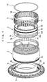
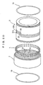
- a ball screw device 1 comprises a nut 2, a screw shaft 3, a multiplicity of balls 4 and a retainer ring 5.
- the nut 2 has a single thread groove 21 continuous from one shaft end to another shaft end formed in the inner peripheral surface thereof.
- the screw shaft 3 has substantially one turn each of two independent thread grooves 31a and 31b formed in the outer peripheral surface thereof.
- the thread groove 21 and the thread grooves 31a and 31b respectively of the nut 2 and the screw shaft 3 are set at an identical lead angle.
- their overlapping region is ensured.
- the thread grooves 31a and 31b In the overlapping region are disposed the thread grooves 31a and 31b, in which each of the balls 4 independently roll and thereby circulate.
- a land that is a ridge 32, is present axially between the thread grooves 31a and 31b of the screw shaft 3.
- Two ball circulation grooves 33 and 34 corresponding to the thread grooves 31a and 31b are provided at the ridge 32.
- the ball circulation grooves 33 and 34 separately couple the upstream side, which the balls roll from, and the downstream side, which the balls roll to, of the corresponding thread grooves 31a and 31b to form closed loops for returning the balls 4 having traveled from the downstream side to the upstream side so that the balls are thereby circulated.
- the ball circulation grooves 33 and 34 sink the balls 4 on the downstream side of the thread grooves 31a and 31b to the inner diameter side so that the balls travel over the ridge 32 of the nut 2 and return to the upstream side.
- substantially one turn used in the description of the thread grooves 31a and 31b means that they have a length of less than one turn, however close to one turn, and the length should be such as to locate the ball circulation grooves 33 and 34 between the downstream and upstream sides of the thread grooves 31a and 31b.
- the retainer ring 5 is formed from a thin cylindrical member and has ball pockets 51 provided at dozens of places on the circumference thereof so that the multiple balls 4 are circumferentially spaced at equal intervals so as not to interfere with one another.
- the ball pockets 51 have an axially elongated elliptical shape, in each of which two of the balls 4 are axially housed.
- the ball pockets 51 have an opening dimension larger than the diameter of the balls 4 in a radial direction, which enables the balls 4 to pass through the ball pockets 51 in the radial direction thereof with room to spare.
- the nut 2 is integrally combined with a bracket 8.
- the screw shaft 3 is non-rotatably and axially immovably fitted to a fixed part such as a case, not shown, or the like, while the nut 2 is rotatably and axially movably disposed with respect to the screw shaft 3.
- the bracket 8 is made of metal material and includes an axially extending internal cylindrical portion 81, an external cylindrical portion 82 concentric with and radially outward of the internal cylindrical portion 81 and an annular plate portion 83 connecting the internal cylindrical portion 81 with the external cylindrical portion 82 on one axial end side.
- the internal cylindrical portion 81 is disposed in a central hole of the screw shaft 3 in a non-contact state and supported with respect to a support shaft, not shown, via a rolling bearing, not shown.
- the external cylindrical portion 82 is integrally engaged with the outer periphery of a region on one axial end side of the nut 2.
- a serration 84 is provided in the inner peripheral surface on the base side of the external cylindrical portion 82.
- a serration 23 is provided in the outer peripheral surface on the back side of the nut 2 in the insertion direction thereof.
- the bracket 8 and the nut 2 are circumferentially combined as a unit in consequence of the serrations 84 and 23 having been engaged with one another.
- a gear 9 made of resin is integrally formed in the outer peripheral surface of the external cylindrical portion 82.
- the thread groove 3 has a reduced diameter portion 35 on the free end side thereof.
- the retainer ring 5 has a radially inward flange 52 on one end thereof.
- the flange 52 of the retainer ring 5 is engaged with the reduced diameter portion 35 of the screw shaft 3.
- a snap ring 10 is engaged with a peripheral groove provided on the reduced diameter portion 35 of the screw shaft 3.
- the snap ring 10 is mounted in a position distant from a step wall surface 36 formed on the border of the reduced diameter portion 35 of the screw shaft 3 and where the thread groove 21 is formed.
- the flange 52 of the retainer ring 5 is disposed between the snap ring 10 and the step wall surface 36 with a slight axial play. By doing so, the retainer ring 5 is arranged to be substantially axially immovable and relatively rotatable with respect to the screw shaft 3.
- the ball circulation grooves 33 and 34 are described in more detail. Because the thread grooves 31a and 31b of the screw shaft 3 and the ball circulation grooves 33 and 34 are of identical shape, the thread groove 31a and the ball circulation groove 33 corresponding thereto are described below.
- the balls 4 are returned from the thread groove 31a-dn on the downstream side to the thread groove 31a-up on the upstream side by the ball circulation groove 33.
- the thread groove 31a is formed into a closed loop having coupled the 31a-up on the upstream side and the 31a-dn on the downstream side by the ball circulation groove 33.
- the balls 4, when rolling in the thread groove 31a roll between the thread groove 31a and the thread groove 21 of the nut 2, and therefore do not necessarily sink to the inner diameter side.
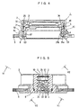
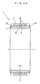
- the balls 4 roll in the ball circulation groove 33, as shown in Fig. 3A, the nut 2 side constitutes the ridge 32. Because the ball circulation groove 33, as shown in Fig.
- the balls 4 are able to sink to the inner diameter side in the ball circulation groove 33 to thereby travel over the nut 2-side ridge 32 and roll into the thread groove 31a-up (thread groove on the upstream side).
- the thread groove 31b a 31b-up on the upstream side and a 31b-dn on the downstream side are coupled by the ball circulation groove 34, which has a depth enough to sink the balls 4 to the inner diameter side.
- the assembling steps of the ball screw device 1 are hereby described.
- the retainer ring 5 is mounted on the screw shaft 3.
- the ball pockets 51 of the retainer ring 5 are coated with grease to the extent of being thereby infilled, and then a required number of the balls 4 are installed in the ball pockets 51.
- the grease used here preferably has enough viscosity to prevent the balls 4 from falling by their own weight and serves to retain the balls 4 inside the ball pockets 51.
- the gear 9 is rotated along with the rotation of a motor, and the nut 2 integral with the gear 9 is synchronously rotated.
- the nut 2 is, being rotated, guided by the screw shaft 3 and linearly moved in one axial direction.
- the state of the ball screw device 1 is shifted from, for example, what is shown in Fig. 3A to Fig. 3B.
- the motor is rotated in the opposite direction, in response to which, the nut 2 is, being rotated in the opposite direction as well, moved in the opposite axial direction. Accordingly, the state of the ball screw device 1 is shifted from, for example, what is shown in Fig. 3B to Fig. 3A.
- the retainer ring 5 is arranged to be rotated by means of the highly precisely manufactured outer peripheral surface of the screw shaft 3 serving to control the rotational wobble of the retainer ring 5 itself in the axial reciprocation of the nut 2 and also to avoid the interference by the retainer ring 5 with theballs 4.
- theball screw device 1 is capable of circulating the balls without using a deflector.
- the ball circulation grooves 33 and 34 are provided in a substantially identical phase and axially adjacent to one another, and therefore the thread grooves 31a and 31b of the screw shaft 3 are axially closely spaced. Consequently, an area axially occupied by the ball circulation grooves 33 and 34 is reduced.
- the balls 4 disposed in the ball circulation grooves 33 and 34 can be subject to neither a radial load nor an axial load, and therefore providing two ball circulation grooves 33 and 34 circumferentially and axially in the vicinity will create a non-load bearing area in a predetermined angle on the circumference of the thread grooves 31a and 31b.
- an angle ⁇ of the region where the ball circulation grooves 33 and 34 are present on the circumference of the thread grooves 31a and 31b, can be small.
- a smaller number of the balls 4 are, therefore, required to be disposed in the ball circulation grooves 33 and 34. Accordingly, the decrease of load bearing performance is controlled to consequently eliminate any possible trouble in practical use.
- the thread grooves 31a and 31b are only provided in a predetermined length in an axially intermediate position thereof, while the both axial end sides thereof have no thread grooves.
- the degree of freedom in design is enhanced, such as being able to variously design the shapes of the inner and outer diameter portions on the both axial end sides of the screw shaft 3.
- thread grooves are not provided on the both axial end sides of the screw shaft 3, wherein at least one axial end side of the screw shaft 3 can be thinner and reduced in weight having enough strength.
- the outer diameter of the screw shaft 3 on at least one axial end side thereof can be reduced, and the reduced diameter portion can be supported by a case or the like.
- the snap ring 10 the outer diameter of the screw shaft 3 on at least one axial end side thereof may be enlarged.
- the snap ring 10 and the large diameter portion of the screw shaft 3 in combination may be used.
- a first mode of use wherein one of the nut 2 and the screw shaft 3 is rotated to have the other axially move
- a second mode of use wherein one of the nut 2 and the screw shaft 3 is axially moved to have the other rotate.
- the first mode of use is referred to as a forward efficiency for converting a torque into a thrust.
- the second mode of use is referred to as a reverse efficiency for converting a thrust into a torque.
- the nut 2 is, being rotated, axially moved.
- the screw shaft 3 is arranged to be non-rotatable and axially immovable to rotate the nut 2.
- the nut 2 is axially moved in the non-rotatable manner.
- the screw shaft 3 is arranged to be axially immovable, while the nut 2 is arranged to be non-rotatable, to rotate the screw shaft 3.
- the screw shaft 3 is, being rotated, axially moved.
- the nut 2 is arranged to be non-rotatable and axially immovable to rotate the screw shaft 3.
- the screw shaft 3 is axially moved in the non-rotatable manner.
- the screw shaft 3 is arranged to be non-rotatable, while the nut 2 is arranged to be axially immovable, to rotate the nut 2.
- the nut 2 is rotated in the axially immovable manner.
- the nut 2 is arranged to be axially immovable, while the screw shaft 3 is arranged to be non-rotatable to have the screw shaft 3 axially move.
- the nut 2 is, being axially moved, rotated.
- the screw shaft 3 is arranged to be axially immovable and non-rotatable to have the nut 2 axially move.
- the screw shaft 3 is rotated in the axially immovable manner.
- the screw shaft 3 is arranged to be axially immovable, while the nut 2 is arranged to be non-rotatable to have the nut 2 axially move.
- the screw shaft 3 is, being axially moved, rotated.
- the nut 2 is arranged to be axially immovable and non-rotatable, to have the screw shaft 3 axially move.
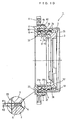
- an inner diameter clearance X1 between the retainer ring 5 and the screw shaft 3 is set at a value smaller than an outer diameter clearance X2 between the retainer ring 5 and the nut 2, as shown in Fig. 10.
- the inner diameter clearance X1 is set at, for example, 0.1 - 0.4 mm.
- the outer peripheral surface of the screw shaft 3, which guides the retainer ring 5, is usually processed to have circularity of 0.1 and surface roughness of 1.6 Ra.
- the circularity is a ratio of a difference between a largest outer diameter and a smallest outer diameter with respect to a designated outer diameter, and Ra is an arithmetic average roughness, both stipulated in the Japan Industrial Standard (JIS).
- the thread grooves 31a and 31b of the screw shaft 3 and the ball circulation grooves 33 and 34 share a common shape. Therefore, one of the thread grooves, 31a, and the ball circulation groove 33 corresponding thereto are hereinafter described.
- the shapes of the ball circulation groove 33 and the portion connecting the thread groove 31a of the screw shaft 3 with the ball circulation groove 33 are formed as follows.
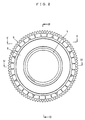
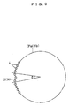
- the circumferential length of the ball circulation groove 33 that is an occupation angle ⁇ shown in Fig. 9, to be relatively larger.
- the balls 4 disposed in the ball circulation groove 33 can be subject to neither a thrust loadnor radial load, it is preferable for the circumferential length of the ball circulation groove 33, that is the occupation angle ⁇ shown in Fig. 9, to be relatively smaller. It is required that the ball circulation groove 33 be designed on the basis of the foregoing aspects.
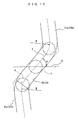
- the shapes of the ball circulation grooves 33 and 34 are described as follows by means of a centrode C drawn by the balls 4 when they roll in the ball circulation grooves 33 and 34.
- an angle ⁇ shown in Fig. 11 is set within the range of 45 - 60 degrees.
- the angle ⁇ refers to a tilting angle of the centrode C drawn by the balls 4 passing through an intermediate region in the rolling direction of the balls in the ball circulation grooves 33 and 34 with respect to a rotational axis ⁇ of the screw shaft 3.
- the tilting angle ⁇ is arranged to be larger, the smoothness in the movement of the balls 4 improves, on the contrary to which the occupation angle ⁇ of the ball circulation grooves 33 and 34 becomes larger resulting in the reduced load capacity. Therefore, the tilting angle ⁇ is arranged to be set within the foregoing range (45 - 60 degrees) in an effort to make it as small as possible so that the occupation angle ⁇ of the ball circulation grooves 33 and 34 are as small as possible so as to increase the load capacity.
- the thread grooves 31a and 31b of the screw shaft 3 and the ball circulation grooves 33 and 34 are coupled as smoothly as possible. More specifically, as shown in Fig. 11, the centrode C of the balls 4 passing through the portions connecting the thread grooves 31a and 31b of the screw shaft 3 with the ball circulation grooves 33 and 34 is arranged to be a curved line having curvature radius R of at least 1. 8 times as long as a diameter r of the balls 4.
- the balls 4 can have a smooth axially winding and rolling movement decreasing effectively abrasion of the balls 4 and the ball circulation grooves 33 and 34.
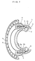
- the ball circulation grooves 33 and 34 are formed to have such a curved shape as to sink radially inward in intermediate regions 33a and 34a in the rolling direction of the balls 4 and also a shape curved or protruding radially outward, as a predetermined shape, in the both end side regions 33b and 34b.
- the both end side regions 33b and 34b may not necessarily have a shape curved radially outward and may be of other predetermined shapes capable of circulating the balls 4 such as a straight and linear shape or some other shape.
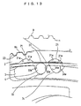
- FIG. 12 shows the semicircular bottom portions of the ball circulation grooves 33 and 34 in section and also shows the balls 4 are in rolling contact with the bottom portions of the ball circulation grooves 33 and 34 for convenient description.
- the ball circulation grooves 33 and 34 have a Gothic arc shape in section, the balls 4 are in rolling contact with the side walls of the ball circulation grooves 33 and 34, which, however, is not shown in Fig. 12.
- the connecting portions 33c and 34c and the vicinity thereof are formed to have a predetermined shape so that the centrode of the balls 4 rolling in the both end side regions 33b and 34b of the ball circulation grooves 33 and 34 and the centrode of the balls 4 rolling in the respective downstream and upstream sides of the thread grooves 31a and 31b of the screw shaft 3 satisfy predetermined conditions in connection with circulation of the balls 4.
- the predetermined conditions are: whether the ball circulation grooves 33 and 34 are of semicircular shape or Gothic arc shape in section, the centrode of the balls 4 satisfies the following intersecting angle ⁇ .
- the intersecting angle ⁇ is the angle at which a first tangent line Y and a second tangent line Z intersects with one another.
- the first tangent line Y is obtained at an intersection point K of a small arc R2 formed by the centrode C of the balls 4 rolling in the both end side regions 33b and 34b of the ball circulation grooves 33 and 34 with respect to a large arc R1 formed by the centrode C of the balls 4 rolling in the thread grooves 31a and 31b, and the second tangent line Z is obtained at the interesection point K with respect to the small arc R2.
- the intersecting angle ⁇ is set at a degree larger than 0 (zero) degree and at most 30 degrees, or preferably at most 20 degrees.
- the intersecting angle ⁇ is 0 degree when a center of curvature P2 of the small arc R2 is disposed on a straight line G connecting a center of curvature P1 of the large arc R1 with the intersection point K.
- the connecting portions 33c and 34c are formed in a shape satisfying the intersecting angle ⁇ .
- the connecting portions 33c and 34c connecting the ball circulation grooves 33 and 34 with the thread grooves 31a and 31b of the screw shaft 3 are arranged to have a shape satisfying the intersecting angle ⁇ , the radial displacement of the balls 4, in entering and exiting between the thread grooves 31a and 31b of the screw shaft 3 and the ball circulation grooves 33 and 34, can be reduced enabling the smooth entry and exit of the balls 4.
- the screw shaft 3 is hardened after the ball circulation grooves 33 and 34 and the thread grooves 31a and 31b of the screw shaft 3 have been formed to be finally finished by polishing or grinding, and the foregoing condition is particularly unfavorable in the polishing step as follows.
- a polishing tool is arranged to be in contact with the thread grooves 31a and 31b of the screw shaft 3, and then the screw shaft 3 is rotated.
- the polishing tool while having a contact with the thread grooves 31a and 31b of the screw shaft 3, does not contact the ball circulation grooves 33 and 34, wherein the ball circulation grooves 33 and 34 cannot be polished.
- the connecting portions 33c and 34c are formed in such a shape as to enlarge the intersecting angle ⁇ to more than 30 degrees, the connecting portions 33c and 34c result in having an acute tip portion.
- the connecting portions 33c and 34c are formed in such a shape as to reduce the intersecting angle 8 to at most 30 degrees, the connecting portions 33c and 34c result in having a round tip portion.
- the intersecting angle ⁇ can also serve as a requisite for not creating an edge in the connecting portions 33c and 34c connecting the ball circulation grooves 33 and 34 with the thread grooves 31a and 31b of the screw shaft 3 in the polishing step.
- the occupation angle ⁇ of the ball circulation grooves 33 and 34 that is an area incapable of bearing a load, is arranged to be as small as possible, in response to which the load capacity is arranged to be as large as possible, and then a rolling resistance affecting the balls 4 rolling in the ball circulation grooves 33 and 34 is arranged to be as small as possible so that the balls 4 consequently roll as smoothly as possible.
- the load capacity and the smoothness of movements can be combined in a well-balanced manner in the ball screw device.
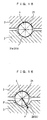
- the section of any of a thread groove 21 of a nut 2, thread grooves 31a and 31b of a screw shaft 3, and ball circulation grooves 33 and 34 is of Gothic arc shape, in which right and left circular side walls are sharply thinned and continuous at the groove bottom portions.
- 21ws are the right and left side walls of the thread groove 21 of the nut 2
- 31bws are the right and left side walls of the thread groove 31b
- 33ws are the right and left side walls of the ball circulation groove 33
- 34ws are the right and left side walls of the ball circulation groove 34.
- the right and left side walls of the thread groove 31a are not shown, but are the same as those of the thread groove 31b.
- a contacting point P of the balls 4 and the ball circulation grooves 33 and 34 which was originally made at the contacting angle of 45° in Fig. 15, moves slowly to near the openings of the ball circulation grooves 33 and 34 (shallower side of the grooves), as shown in Fig. 16.
- the balls 4 are affected by a force F in the direction where they sink to the ball circulation grooves 33 and 34.
- downstream sides 31a-dn and 31b-dn and upstream sides 31a-up and 31b-up of the thread grooves 31a and 31b of the screw shaft 3 are coupled by the ball circulation grooves 33 and 34 to form closed loops.
- the balls 4 having rolled to the downstream sides 31a-dn and 31b-dn of the thread grooves 31a and 31b are sunk to the inner diameter side to travel over the ridge 22 of the nut 2 so that they are guided to the upstream sides 31a-up and 31b-up to be thereby circulated.
- the ball circulation grooves 33 and 34 being formed in a Gothic arc shape in section, when the balls 4, at the time of circulating, move from the thread grooves 31a and 31b of the screw shaft 3 to the ball circulation grooves 33 and 34, the contacting point P of the balls 4 and the ball circulation grooves 33 and 34 is near the openings of the ball circulation grooves 33 and 34. For this reason, the force F affects the balls 4 in the direction where they sink into theball circulation grooves 33 and 34, which prevents the balls 4 from running on and getting stuck at the ridge 32 of the screw shaft 3 resulting in smooth circulation of the balls 4.
- retainer ring 5 for retaining the balls 4 prevents interference between the balls 4 in the thread grooves 21, 31a and 31b andprovides the smooth relative rotation between the nut 2 and the screw shaft 3.
- the thread grooves 31a and 31b of the screw shaft 3 may not necessarily be two, and can be one, three or more.
- the ball circulation grooves 33 and 34 may be arranged axially adjacent to one another or in a circumferentially different phase.
- Fig. 17 shows the X portion of Fig. 7 enlarged
- Fig. 18 shows the XI portion of Fig. 4 enlarged.
- a chamfer 24 is formed along the side edges of a thread groove 21 of a nut 2 to avoid any contact with balls 4 when entering and exiting the ball circulation grooves 33 and 34.
- the chamfer 24 is formed by turning with a turning tool (cutting tool) or grind stone the entire length of the thread groove 21 along both side edges thereof constituting the border of the thread groove 21 of the nut 2 and a ridge 32. It is preferable to have the chamfer deep, the deeper the better, in terms of safely avoiding any contact with the balls 4.
- the chamfer should be set at a depth in which the balls 4 can be safely guided and any contact with the balls 4 can be safely avoided.
- the downstream and upstream sides of the thread grooves 31a and 31b of the screw shaft 3 are coupled by the ball circulation grooves 33 and 34 to form closed loops. Then, the balls 4 having rolled to the downstream side of the thread grooves 31a and 31b of the screw shaft 3 are sunk to the inner diameter side to travel over the ridge 32 of the nut 2 so that they are guided to the upstream side of the thread grooves 31a and 31b to be thereby circulated.
- the ball screw device shown in Figs. 19 and 20 is the type of device with a retainer ring 5 unused therein.
- the retainer-ring-free ball screw device 1 comprises a nut 2, a screw shaft 3, and a multiplicity of balls 4.
- the nut 2 has a thread groove 21 formed in the inner peripheral surface thereof
- the screw shaft 3 has thread grooves 31a and 31b formed in the outer peripheral surface thereof.
- the multiple balls 4 are interposed between the thread groove 21 and the thread grooves 31a and 31b.
- the single thread groove 21 continuous from one shaft end to another shaft end.
- In the axially intermediate region of the screw shaft 3 are formed substantially one turn each of independent thread grooves.
- the thread groove 21 of the nut 2 and the thread grooves 31a and 31b of the screw shaft 3 are set at an identical lead angle.
- the thread grooves 21, 31a and 31b are arranged to have a Gothic arc shape in section, but may have a semicircular shape in section.
- a ridge 32 is present between one of the thread grooves, 31a and the other, 31b.
- ball circulation grooves 33 and 34 which serve to form the respective thread grooves 31a and 31b into independent closed loops.
- the ball circulation grooves 33 and 34 respectively couple the upstream and downstream sides of the thread grooves 31a and 31b and have such a meandering shape as to sink the balls 4 on the downstream side of the thread grooves 31a and 31b to the inner diameter side so that the balls 4 travel over the ridge 22 of the nut 2 to be thereby returned to the upstream side.
- the ball circulation grooves 33 and 34 enable the multiple balls 4 disposed in the respective thread grooves 31a and 31b to independently roll and circulate.
- Theball circulation grooves 33 and 34 are arranged to have a semicircular shape in section, but may have a Gothic arc shape in section.
- Circumferential grooves 35 are respectively provided in the outer peripheral surfaces of the screw shaft groove 3 on the axial both end sides thereof.
- the circumferential grooves 35 are respectively engaged with snap rings 7.
- the outer diameters of the snap rings 10 are set at a value larger than the inner diameter of the nut 2, whereby the snap rings 10 restrict the axial traveling stroke of the nut 2.
- the nut 2 is, for example, supported so as to freely rotate, and the screw shaft 3 is mounted in a non-rotatable and axially immovable manner.
- the nut 2 when rotated, axially slides on the screw shaft 3 between the snap rings 10, as shown in a chain double-dashed line in Fig. 1.
- substantially one turn of a thread groove 31a is formed on the screw shaft 3, and the thread groove 31a may be formed into a closed loop by the ball circulation groove 33, as shown in Fig. 21.
- the balls 4 can contact the thread groove 21 of the nut 2 and the thread groove 31a of the screw shaft 3 at four points. This, when a moment load acts on the nut 2, enables the tilting thereof to be controlled.
- substantially one turn of the thread groove 31a is formed on the screw shaft 3, and the thread groove 31a may be formed into a closed loop by the ball circulation groove 33, as shown in Fig. 22.
- the thread groove 31a of the screw shaft 3 and the ball circulation groove 33 may have a semicircular shape in section.
- a recess portion 38 may be provided in the region of the screw shaft 3, where the ball circulation grooves 33 and 34 are supposed to be formed, while a block 12, on which the ball circulation grooves 33 and 34 have been formed, may be fitted into the recess portion 38.
- the block 12 which is mounted on the screw shaft 3 with high precision in contrast to the conventional deflectors to be attached to the nut 2 by an adhesive, can achieve a precise positioning between the ball circulation grooves 33 and 34 and the thread grooves 31a and 31b.
- the working step of forming the ball circulation grooves 33 and 34 thereon can be simplified compared to forming the ball circulation grooves 33 and 34 directly in the outer peripheral surface of the screw shaft 3.
- the recess portion 38 may be a through opening.
- the present invention can be applied to a method of converting a rotational movement into a linear movement and vise versa in machine tools, semiconductor devices, precision position tables, robots and conveying equipment.
Landscapes
- Engineering & Computer Science (AREA)
- General Engineering & Computer Science (AREA)
- Mechanical Engineering (AREA)
- Transmission Devices (AREA)
Abstract
Description
Claims (7)
- A ball screw device comprising:a screw shaft having substantially one turn of at least one thread groove provided in an outer peripheral surface thereof;a nut externally mounted on the screw shaft and having a thread groove provided in an inner peripheral surface thereof at an angle substantially identical to that of the thread groove; anda plurality of balls interposed between the respective thread grooves, whereina ball circulation groove for coupling downstream and upstream sides of the thread groove of the screw shaft are provided on the screw shaft so that the balls are returned from the downstream side to the upstream side to be thereby circulated in the thread groove of the screw shaft,the ball circulation groove has an intermediate region in a direction of rolling balls having such a curved shape as to sink radially inward and both end side regions positioned on both sides of the intermediate region and having a predetermined shape, andthe ball circulation groove configured in the manner in that a centrode of the balls rolling in the both end side regions and a centrode of the balls rolling in the thread groove of the screw shaft satisfy predetermined conditions with respect to the circulation of the balls.
- A ball screw device as claimed in Claim 1, wherein
the predetermined conditions are that an angle, at which a first tangent line obtained at an intersection point of a small arc formed by the centrode of the balls rolling in the both end regions of the ball circulation groove with respect to a large arc formed by the centrode of the balls rolling in the thread groove of the screw shaft intersects with a second tangent line obtained at the intersection point with respect to the small arc, is set at a degree larger than 0 degree and at most 30 degrees. - A ball screw device as claimed in Claim 1, wherein
the both end side regions of the ball circulation groove have a shape protruding radially outward. - A ball screw device as claimed in Claim 1, wherein
in the screw shaft is provided substantially one turn each of two independent thread grooves and two ball circulation grooves, corresponding to the respective thread grooves of the screw shaft, for separately coupling the respective downstream and upstream sides of the thread grooves; and
the respective ball circulation grooves are disposed in a substantially identical phase in an axial direction. - A ball screw device as claimed in Claim 1, wherein
a retainer ring for rotatably retaining the balls is mounted on an outer periphery of the screw shaft so as to relatively rotate with respect to the screw shaft in an axially fixed position. - A ball screw device as claimed in Claim 1, wherein
any of the thread groove of the screw shaft, the thread groove of the nut and the ball circulation groove has a Gothic arc shape in section. - A ball screw device as claimed in Claim 1, wherein
a chamfer for avoiding contact with the balls when entering and exiting the ball circulation groove is formed on side edges of the thread groove of the nut.
Applications Claiming Priority (7)
| Application Number | Priority Date | Filing Date | Title |
|---|---|---|---|
| JP2001276195 | 2001-09-12 | ||
| JP2001276195A JP2003083414A (en) | 2001-09-12 | 2001-09-12 | Ball screw device |
| JP2001288129A JP5017761B2 (en) | 2001-09-21 | 2001-09-21 | Ball screw device |
| JP2001288129 | 2001-09-21 | ||
| JP2001288630 | 2001-09-21 | ||
| JP2001288630 | 2001-09-21 | ||
| PCT/JP2002/009264 WO2003025429A1 (en) | 2001-09-12 | 2002-09-11 | Ball screw device |
Publications (3)
| Publication Number | Publication Date |
|---|---|
| EP1426660A1 true EP1426660A1 (en) | 2004-06-09 |
| EP1426660A4 EP1426660A4 (en) | 2008-11-19 |
| EP1426660B1 EP1426660B1 (en) | 2010-03-03 |
Family
ID=27347483
Family Applications (1)
| Application Number | Title | Priority Date | Filing Date |
|---|---|---|---|
| EP02767945A Expired - Lifetime EP1426660B1 (en) | 2001-09-12 | 2002-09-11 | Ball screw device |
Country Status (6)
| Country | Link |
|---|---|
| US (1) | US7305902B2 (en) |
| EP (1) | EP1426660B1 (en) |
| KR (1) | KR100822130B1 (en) |
| CN (1) | CN100344898C (en) |
| DE (1) | DE60235558D1 (en) |
| WO (1) | WO2003025429A1 (en) |
Cited By (2)
| Publication number | Priority date | Publication date | Assignee | Title |
|---|---|---|---|---|
| EP1602858A4 (en) * | 2003-02-18 | 2007-04-25 | Jtekt Corp | Ball screw device |
| EP3252344A1 (en) * | 2016-05-30 | 2017-12-06 | Jtekt Corporation | Ball screw device and steering system |
Families Citing this family (12)
| Publication number | Priority date | Publication date | Assignee | Title |
|---|---|---|---|---|
| JP2005344782A (en) * | 2004-06-01 | 2005-12-15 | Ntn Corp | Ball screw |
| JP2006090421A (en) * | 2004-09-24 | 2006-04-06 | Nsk Ltd | Ball screw mechanism |
| US7530282B2 (en) * | 2005-10-25 | 2009-05-12 | Nsk Ltd. | Ball screw apparatus |
| JP5255503B2 (en) * | 2009-03-31 | 2013-08-07 | Thk株式会社 | Rolling element screw device |
| CN102869463B (en) | 2010-03-31 | 2015-07-08 | 日本精工株式会社 | Ball screw and method for manufacturing ball screw nut |
| TWI444543B (en) * | 2011-11-28 | 2014-07-11 | Hiwin Tech Corp | Internal recirculating ball screw |
| CN103148185B (en) * | 2011-12-06 | 2016-02-03 | 上银科技股份有限公司 | Internal-circulating ball screw |
| JP5978903B2 (en) * | 2012-10-10 | 2016-08-24 | 株式会社ジェイテクト | Ball screw device and electric power steering device provided with the same |
| JP6601792B2 (en) * | 2015-09-24 | 2019-11-06 | Ntn株式会社 | Ball screw |
| CN106969110B (en) * | 2016-01-14 | 2019-03-19 | 上银科技股份有限公司 | Axial recirculating ball screw |
| EP3540263B1 (en) * | 2016-11-14 | 2023-11-22 | NSK Ltd. | Ball screw |
| CN116324222B (en) * | 2021-08-24 | 2026-04-24 | 日本精工株式会社 | Ball screw device and its manufacturing method |
Family Cites Families (13)
| Publication number | Priority date | Publication date | Assignee | Title |
|---|---|---|---|---|
| US470921A (en) | 1892-03-15 | Taining them | ||
| US3244022A (en) * | 1964-04-20 | 1966-04-05 | Sargent Engineering Corp | Ball screw and nut assembly |
| US3537666A (en) * | 1969-03-20 | 1970-11-03 | Gerald F Lewis | Retractor for seatbelts and the like |
| IT1070470B (en) | 1975-10-28 | 1985-03-29 | Arnold Franz | BALL SCREW MECHANISM |
| JPS5917058A (en) | 1982-07-20 | 1984-01-28 | Hiroshi Mito | Helicoid screw with balls |
| JPS5959556A (en) | 1982-09-30 | 1984-04-05 | Nissin Kogyo Kk | Brake oil pressure controller for vehicle |
| JPS60263764A (en) * | 1984-06-12 | 1985-12-27 | Nippon Seiko Kk | Ball screw device |
| US5358265A (en) * | 1990-08-13 | 1994-10-25 | Yaple Winfred E | Motorcycle lift stand and actuator |
| JPH0510412A (en) * | 1991-07-05 | 1993-01-19 | Mitsubishi Heavy Ind Ltd | Ball screw |
| JPH0552423U (en) * | 1991-12-24 | 1993-07-13 | 日本精工株式会社 | Ball screw device |
| JP3325679B2 (en) * | 1993-12-10 | 2002-09-17 | 日本精工株式会社 | Ball groove shape of ball screw |
| JP3648985B2 (en) * | 1998-06-30 | 2005-05-18 | 日本精工株式会社 | Ball screw with cage type cage |
| NL1014561C2 (en) * | 2000-03-03 | 2001-09-04 | Skf Eng & Res Centre Bv | Screw actuator. |
-
2002
- 2002-09-11 EP EP02767945A patent/EP1426660B1/en not_active Expired - Lifetime
- 2002-09-11 KR KR1020047003661A patent/KR100822130B1/en not_active Expired - Fee Related
- 2002-09-11 CN CNB028170083A patent/CN100344898C/en not_active Expired - Fee Related
- 2002-09-11 US US10/488,601 patent/US7305902B2/en not_active Expired - Lifetime
- 2002-09-11 DE DE60235558T patent/DE60235558D1/en not_active Expired - Lifetime
- 2002-09-11 WO PCT/JP2002/009264 patent/WO2003025429A1/en not_active Ceased
Cited By (3)
| Publication number | Priority date | Publication date | Assignee | Title |
|---|---|---|---|---|
| EP1602858A4 (en) * | 2003-02-18 | 2007-04-25 | Jtekt Corp | Ball screw device |
| EP3252344A1 (en) * | 2016-05-30 | 2017-12-06 | Jtekt Corporation | Ball screw device and steering system |
| US10030746B2 (en) | 2016-05-30 | 2018-07-24 | Jtekt Corporation | Ball screw device and steering system |
Also Published As
| Publication number | Publication date |
|---|---|
| CN1549909A (en) | 2004-11-24 |
| US20040237685A1 (en) | 2004-12-02 |
| CN100344898C (en) | 2007-10-24 |
| DE60235558D1 (en) | 2010-04-15 |
| EP1426660A4 (en) | 2008-11-19 |
| WO2003025429A1 (en) | 2003-03-27 |
| KR100822130B1 (en) | 2008-04-15 |
| US7305902B2 (en) | 2007-12-11 |
| KR20040044901A (en) | 2004-05-31 |
| EP1426660B1 (en) | 2010-03-03 |
Similar Documents
| Publication | Publication Date | Title |
|---|---|---|
| EP1426660B1 (en) | Ball screw device | |
| EP1424513B1 (en) | Ball screw device | |
| JPH0684776B2 (en) | Combined motion guide unit and combined motion guide device using the same | |
| JP2022091734A (en) | Coaxial gear device | |
| EP0950823A2 (en) | Constant velocity universal joint | |
| JP2002089651A (en) | Rolling element spacer of rolling guide device | |
| US6978693B2 (en) | Ball screw | |
| JPH11210858A (en) | Circulation type screw device | |
| JP2003166616A (en) | Ball screw device | |
| JP2017207092A (en) | Ball screw and ball screw manufacturing method | |
| CN100427764C (en) | Separator, and linear guide and linear motion device using the same | |
| EP1602858B1 (en) | Ball screw device | |
| EP1607658A1 (en) | Ball screw device | |
| CN101036004B (en) | Roller screw | |
| JP7302171B2 (en) | ball screw | |
| JP2008286323A (en) | Linear motion mechanism | |
| JP2000161459A (en) | Cross roller screw device | |
| JP2504812Y2 (en) | Ball bearing for linear bearing | |
| US6584869B2 (en) | Ball screw | |
| JP2023149493A (en) | friction transmission device | |
| JP2003139135A (en) | Linear bush and raceway shaft for linear bush | |
| JP5017761B2 (en) | Ball screw device | |
| JP2003269568A (en) | Linear motion device | |
| CN100419286C (en) | Linear Motion Devices and Linear Guides | |
| JP7584015B2 (en) | Ball screw |
Legal Events
| Date | Code | Title | Description |
|---|---|---|---|
| PUAI | Public reference made under article 153(3) epc to a published international application that has entered the european phase |
Free format text: ORIGINAL CODE: 0009012 |
|
| 17P | Request for examination filed |
Effective date: 20040311 |
|
| AK | Designated contracting states |
Kind code of ref document: A1 Designated state(s): AT BE BG CH CY CZ DE DK EE ES FI FR GB GR IE IT LI LU MC NL PT SE SK TR |
|
| RAP1 | Party data changed (applicant data changed or rights of an application transferred) |
Owner name: JTEKT CORPORATION |
|
| A4 | Supplementary search report drawn up and despatched |
Effective date: 20081020 |
|
| 17Q | First examination report despatched |
Effective date: 20090223 |
|
| GRAP | Despatch of communication of intention to grant a patent |
Free format text: ORIGINAL CODE: EPIDOSNIGR1 |
|
| GRAS | Grant fee paid |
Free format text: ORIGINAL CODE: EPIDOSNIGR3 |
|
| GRAA | (expected) grant |
Free format text: ORIGINAL CODE: 0009210 |
|
| AK | Designated contracting states |
Kind code of ref document: B1 Designated state(s): DE FR GB |
|
| REG | Reference to a national code |
Ref country code: GB Ref legal event code: FG4D |
|
| REF | Corresponds to: |
Ref document number: 60235558 Country of ref document: DE Date of ref document: 20100415 Kind code of ref document: P |
|
| PLBE | No opposition filed within time limit |
Free format text: ORIGINAL CODE: 0009261 |
|
| STAA | Information on the status of an ep patent application or granted ep patent |
Free format text: STATUS: NO OPPOSITION FILED WITHIN TIME LIMIT |
|
| 26N | No opposition filed |
Effective date: 20101206 |
|
| GBPC | Gb: european patent ceased through non-payment of renewal fee |
Effective date: 20100911 |
|
| REG | Reference to a national code |
Ref country code: FR Ref legal event code: ST Effective date: 20110531 |
|
| PG25 | Lapsed in a contracting state [announced via postgrant information from national office to epo] |
Ref country code: FR Free format text: LAPSE BECAUSE OF NON-PAYMENT OF DUE FEES Effective date: 20100930 |
|
| PG25 | Lapsed in a contracting state [announced via postgrant information from national office to epo] |
Ref country code: GB Free format text: LAPSE BECAUSE OF NON-PAYMENT OF DUE FEES Effective date: 20100911 |
|
| PGFP | Annual fee paid to national office [announced via postgrant information from national office to epo] |
Ref country code: DE Payment date: 20200901 Year of fee payment: 19 |
|
| REG | Reference to a national code |
Ref country code: DE Ref legal event code: R119 Ref document number: 60235558 Country of ref document: DE |
|
| PG25 | Lapsed in a contracting state [announced via postgrant information from national office to epo] |
Ref country code: DE Free format text: LAPSE BECAUSE OF NON-PAYMENT OF DUE FEES Effective date: 20220401 |