EP1426623A1 - Kolbenstangenloser Linearantrieb - Google Patents
Kolbenstangenloser Linearantrieb Download PDFInfo
- Publication number
- EP1426623A1 EP1426623A1 EP03024228A EP03024228A EP1426623A1 EP 1426623 A1 EP1426623 A1 EP 1426623A1 EP 03024228 A EP03024228 A EP 03024228A EP 03024228 A EP03024228 A EP 03024228A EP 1426623 A1 EP1426623 A1 EP 1426623A1
- Authority
- EP
- European Patent Office
- Prior art keywords
- stop
- housing
- linear drive
- driver
- drive according
- Prior art date
- Legal status (The legal status is an assumption and is not a legal conclusion. Google has not performed a legal analysis and makes no representation as to the accuracy of the status listed.)
- Granted
Links
- 230000033001 locomotion Effects 0.000 claims abstract description 21
- 230000008878 coupling Effects 0.000 claims description 8
- 238000010168 coupling process Methods 0.000 claims description 8
- 238000005859 coupling reaction Methods 0.000 claims description 8
- 230000005540 biological transmission Effects 0.000 claims description 7
- 238000007789 sealing Methods 0.000 claims description 7
- 239000012530 fluid Substances 0.000 claims description 6
- 230000001154 acute effect Effects 0.000 claims description 2
- 238000004026 adhesive bonding Methods 0.000 claims description 2
- 239000000853 adhesive Substances 0.000 description 5
- 230000001070 adhesive effect Effects 0.000 description 5
- 239000000463 material Substances 0.000 description 4
- 230000035939 shock Effects 0.000 description 4
- 239000006096 absorbing agent Substances 0.000 description 3
- 239000000356 contaminant Substances 0.000 description 2
- 230000000149 penetrating effect Effects 0.000 description 2
- 230000001133 acceleration Effects 0.000 description 1
- 239000000872 buffer Substances 0.000 description 1
- 239000000969 carrier Substances 0.000 description 1
- 238000010276 construction Methods 0.000 description 1
- 238000013016 damping Methods 0.000 description 1
- 238000011161 development Methods 0.000 description 1
- 230000018109 developmental process Effects 0.000 description 1
- 230000000694 effects Effects 0.000 description 1
- 238000001125 extrusion Methods 0.000 description 1
- 238000009434 installation Methods 0.000 description 1
- 238000004519 manufacturing process Methods 0.000 description 1
- 230000000873 masking effect Effects 0.000 description 1
- 230000035515 penetration Effects 0.000 description 1
- 230000008092 positive effect Effects 0.000 description 1
- 238000005096 rolling process Methods 0.000 description 1
- 238000003466 welding Methods 0.000 description 1
Images


Classifications
-
- F—MECHANICAL ENGINEERING; LIGHTING; HEATING; WEAPONS; BLASTING
- F15—FLUID-PRESSURE ACTUATORS; HYDRAULICS OR PNEUMATICS IN GENERAL
- F15B—SYSTEMS ACTING BY MEANS OF FLUIDS IN GENERAL; FLUID-PRESSURE ACTUATORS, e.g. SERVOMOTORS; DETAILS OF FLUID-PRESSURE SYSTEMS, NOT OTHERWISE PROVIDED FOR
- F15B15/00—Fluid-actuated devices for displacing a member from one position to another; Gearing associated therewith
- F15B15/20—Other details, e.g. assembly with regulating devices
- F15B15/24—Other details, e.g. assembly with regulating devices for restricting the stroke
-
- F—MECHANICAL ENGINEERING; LIGHTING; HEATING; WEAPONS; BLASTING
- F15—FLUID-PRESSURE ACTUATORS; HYDRAULICS OR PNEUMATICS IN GENERAL
- F15B—SYSTEMS ACTING BY MEANS OF FLUIDS IN GENERAL; FLUID-PRESSURE ACTUATORS, e.g. SERVOMOTORS; DETAILS OF FLUID-PRESSURE SYSTEMS, NOT OTHERWISE PROVIDED FOR
- F15B15/00—Fluid-actuated devices for displacing a member from one position to another; Gearing associated therewith
- F15B15/08—Characterised by the construction of the motor unit
- F15B15/082—Characterised by the construction of the motor unit the motor being of the slotted cylinder type
Definitions
- the invention relates to a rodless linear drive, with an elongated housing that has a recording space for a drive part movable in the longitudinal direction of the housing has a longitudinal slot of the housing penetrating driver motion-coupled with a guide carriage is on a linear guide fixed to the housing is adjustable in the longitudinal direction of the housing.
- the stop device is expediently on a side surface of the guide carriage, the one substantially has rectangular plan and in particular on the top with a movable one for fastening Components serving wing is provided.
- the stop device prefferably be provided with two individual attachment units, that for the travel limit in one of the two possible directions of movement of the guide carriage are responsible, each on the two stop units one of two opposed to each other in the longitudinal direction of the housing oriented stop surfaces is provided with a counter-stop protruding into the travel path can work together.
- the driver can only one or at the same time on both stop units be attached.
- a particularly flat construction results itself when the two stop units in the longitudinal direction of the housing are arranged one behind the other.
- the two stop units each in the direction of when hitting a counterstop they act positively on the guide carriage are supported.
- the driver remains and thus also the force associated with the driver Drive part decouples from the impact forces what has a positive effect on the service life. It also ensures that even with a hard impact no change in the relative position between that on the stop unit provided stop surface and the guide carriage occurs.
- the two stop units are made after the desired adjustment expediently firmly together connected so that between them in the fully installed state in the longitudinal direction of the housing - power transmission possible is. This ensures that the relative position between the driver and the guide carriage in the longitudinal direction of the housing not changed even if between these two components, due to high accelerations and / or high loads to be transported, large Forces work.
- the connection between the two stop units expediently takes place through a material bond, in particular by gluing.
- the stop unit is in particular in one piece educated. It has one connected to the driver Holding section and one for cooperation with one of the Counterstop serving as stop surface, the integral components the relevant stop unit.
- the attachment of the driver to only one stop unit is recommended for linear drives of smaller sizes. Especially with larger sizes, a simultaneous Attachment of the driver to both stop units preferred.
- the two stop units each one for cooperation with one Counter stop provided and a part for attachment of the driver provided holding part, the two Parts of a respective stop unit during assembly adjustable relative to each other in the longitudinal direction of the housing are so that an independent adjustment of the stop part and the holding part of a respective stop unit is possible. You are therefore very flexible with the required Attachment of the driver, the one taken there Do not adjust to the positioning of the stop parts effect.
- the stop part and the holding part of a respective Stop unit after adjustment and fastening expediently additionally cohesively with each other connected and thereby secured in position.
- the driver expediently engages with a coupling section between those spaced in the longitudinal direction of the housing Fastening parts of the two stop units and is with both fasteners in the longitudinal direction of the housing connected without play. This way you get one very precise power transmission with correspondingly high positioning precision.
- the measures provided for fastening the driver are particularly designed so that the driver on the assigned stop unit in a longitudinal direction of the housing right-angled housing transverse plane in variable relative positions is definable. With a screw attachment can this be accomplished, for example, that an elongated hole is provided on the driver, the allows the necessary freedom. Alternatively suitable these measures look very good to existing manufacturing and / or Compensate assembly tolerances.
- the linear drive can be designed as an electrically operated type be and have, for example, a spindle drive, which is a drive part designed as a spindle nut is able to shift linearly. It is particularly advantageous however, an embodiment in which the drive part as Piston is formed and the actuating force by applying fluid is produced. In such a case, that is Longitudinal slot assigned a band-like sealing device, the uncontrolled fluid outlet through the longitudinal slot prevented through.
- the exemplary embodiment shows an overall reference number 1 designated rodless linear drive in by Fluid power actuated design. It is especially for one Operation with compressed air.
- the linear drive 1 has an elongated housing 2, with a preferably cylindrical contoured inside Recording space 3 delimiting housing tube 2a, on the front an end cover 4 is fastened on both sides.
- drivable drive part 6 which is designed as a piston is and the receiving space 3 in two axially successive Working chambers divided fluid-tight.
- connection openings 7, which are common in the exemplary embodiment a single end cover 4 are provided, one Supply and discharge of pressure medium in relation to the work rooms respectively.
- the drive part 6 can be cause a drive movement in the longitudinal direction 5 of the housing.
- the drive movement of the drive part 6 can be outside tap the housing 2 on a guide carriage 8, the by means of a driver 12 with the drive part 6 in the longitudinal direction of the housing 5 is motion-coupled.
- the guide carriage 8 is on a linear guide fixed to the housing 13 guided in the longitudinal direction 5 of the housing.
- the linear guide 13 is aligned parallel to the housing 2.
- the linear guide 13 on the outer surface is preferred of the housing tube 2a arranged, being in the embodiment along its entire length with the casing tube 2a is connected. It is conveniently one Guide rail 17 formed, in particular screwless the outer surface of the housing 2 is fixed.
- the embodiment shows a design in which the guide rail 17, in particular by extrusion, in one piece with the housing tube 2a is formed.
- the guide carriage 8 preferably has a U-like cross section and overlaps the linear guide 13 like a rider. there he cooperates with his two on the linear guide 13 sled legs flanking opposite long sides 11 each with one on the associated long side of the Linear guide 13 provided guide section 23.
- the latter are preferably formed by guideways that overlap extend the entire length of the linear guide 13.
- the Sled legs 11 can be used for leading cooperation the guide section 23 with rolling or not shown Be equipped with sliding devices.
- the wall of the housing tube 2a with a longitudinal slot 26. This opens with an inner slot opening 27 in the Recording room 3 and with an opposite outer Slot opening 28 to the longitudinal outer surface 31 of the housing tube 2a from.
- the longitudinal slot 26 preferably extends over the entire length of the housing tube 2a. It runs in a dash-dotted slot plane 32, which at Embodiment with respect to one of the two guide sections 23 of the linear guide 13 spanned guide level 24 runs inclined, in particular under one shown in Figure 3 acute angle 33.
- the outer Slot opening 28 faces the guide plane 24.
- the top extends through the longitudinal slot 26 mentioned driver 12. It is with a subsequently as a fastening section 34 designated inner end portion such coupled to the drive part 6 that he with this forms a drive unit 35, which is always only common is movable in the longitudinal direction 5 of the housing. With others Words the driver 12 makes the linear movement of the drive part 6 play-free with.
- the fastening section 34 is fork-like trained and form-fitting from the side plugged onto the drive part 6 that in the longitudinal direction of the housing 5 a backlash-free, positive connection is present.
- the driver 12 On its outside of the longitudinal slot 26 and as Coupling section 36 is designated outer end portion the driver 12 indirectly, with the interposition of a reference the guide carriage 8 separate stop device 37, with the guide carriage 8 in the longitudinal direction of the housing 5 also motion-free coupled without play.
- the longitudinal slot 26 is one assigned band-like, flexible sealing device 38, which is able to axially the longitudinal slot 26 on both sides of the Seal driver 12 to the environment, so that the desired Fluid exposure is possible.
- the sealing device 38 In the area of the driver 12, the sealing device 38 from the longitudinal slot 26 lifted to allow the passage of the driver 12.
- the sealing device contains 38 an interior responsible for the aforementioned sealing Sealing tape 42 in the area of the inner slot opening 27 cooperate with the slot flanks of the longitudinal slot 26 can.
- there is also an exterior Masking tape 43 is provided in the area of the outer Slit opening 28 prevents contaminants from entering the Longitudinal slot 26 prevented.
- the stop device 37 has a double function. On the one hand As already indicated, it transfers them without play in the longitudinal direction of the housing 5 oriented driving force from driver 12 on the guide carriage 8. On the other hand, it serves to limit the travel of the slide 8 - also as a stroke limitation identifiable - with respect to the housing 2 by adding Reaching the desired end positions of the guide carriage 8 cooperates with counter-stops 39a, 39b fastened on the housing.
- the stop device 37 is on an assembly area below 44 designated side surface of the guide carriage 8 mounted. It is one of the two longitudinal side faces of the total one essentially rectangular guide slide 8. The opposite side surface of the carriage 8 contains no slings. As can be seen from Figure 3 is, the stop device 37 is expedient at the level of management level 24 and near the interface between the management level 24 and the oblique Slot level 32.
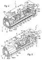
- FIGS. 4 and 5 show two alternative embodiments the stop device 37, in the following, insofar as nothing stated otherwise, a common description is given and where corresponding components with matching Reference numerals are provided.
- the stop device 37 contains two individual stop units 45a, 45b, which - in the longitudinal direction of the housing 5 in a row - independently of each other on the assembly area 44 are mounted.
- first stop unit 45a has one in the direction of the one, first direction of movement 46a first stop surface 47a while on the other, second Stop unit 45b one in the other, second direction of movement 46b facing second stop surface 47b is provided is.
- the counter stops 39a, 39b are assigned to the two end regions of the housing 2 and attached to the end caps 4 in the exemplary embodiment, the - at least in the area of the counter stops 39a, 39b - protrude laterally over the circumference of the casing tube 2a.
- the counter stops 39a, 39b each for damping the end impact of the movement unit serving shock absorber 52, the counter abutment surfaces 48a, 48b on a limitedly movable shock absorbing element are provided.
- shock absorbers 52 but also part of the respectively assigned stop unit 45a, 45b.
- An embodiment without Shock absorber 52 is possible, especially in connection with other measures to mitigate the impact, such as rubber buffers or similar.
- stop devices 37 of the figures 4 and 5 differ fundamentally in that in Case of Figure 4, the driver 12 simultaneously on both stop units 45a, 45b is fastened, while according to FIG 5 only fixed to the first stop unit 45a is.
- Both embodiments have in common that the two stop units 45a, 45b each at least in the direction the impact on a counter-stop 39a, 39b impact force 53a, 53b acting positively on the guide carriage 8 are supported.
- Each stop unit 45a, 45b has one in the direction of which it is applied Impact force 53a, 53b facing support surface 54a, 54b, on a facing counter support surface 55a, 55b of the guide carriage 8 is present.
- the support surface 54a, 54b of a gradation of the relevant stop unit 45a, 45b is formed, and the respectively assigned counter support surface 55a, 55b is located on a corner area of the guide carriage 8, especially in the area of the front and rear End up.
- a stop unit 45a, 45b strikes a counter stop 39a, 39b, the impact force 53a, 53b over the abutting support and counter support surfaces 54a, 55a or 54b, 55b introduced directly into the guide carriage 8, during the driver 12 and thus also with this connected drive part 6 are decoupled in terms of force.
- the two embodiments also have in common that the two separately formed stop units 45a, 45b independently of one another on the guide carriage 8 are attached - via first and second fastening means 56a, 56b - which creates the possibility during assembly the two stop units 45a, 45b relative to one another and also adjustable with reference to the slide 8. This can cause any positional deviations between the driver 12 and the guide carriage 8 are taken into account, without causing tension within the movement unit.
- the two stop units 45a, 45b each formed in two parts. They contain one each for cooperation with one of the counterstops 39a, 39b provided and thus one of the stop surfaces 47a, 47b having stop part 57 and one for fastening of the driver 12 provided, separate holding part 58. These two parts 57, 58 are during assembly on Guide carriage 8 relative to each other in the longitudinal direction of the housing 5 adjustable to adapt to the relative position between driver 12 and guide carriage 8 to make can.
- the stop part 57 and the holding part 58 are expedient each designed L-shaped. They each have a mounting leg 62 which is in the longitudinal direction of the housing 5 are aligned and a bit in the Longitudinal direction 5 overlap.
- the mounting leg 62 of the holding part 58 bears against the assembly surface 44 and thus sits between the guide carriage 8 and the one covering it Fastening leg 62 of the stop part 57. This arrangement could also be reversed.
- the second leg is a Stop surface 47a, 47b having stop leg 63, in Case of the holding part 58 for fastening the driver 12 serving holding leg 64.
- stop leg 63 and holding leg 64 each protrude in a direction longitudinal to the housing 5 right-angled housing transverse plane from the guide slide 8 away and are located at opposite ends of the respective stop unit 45a, 45b.
- the holding leg 64 of the the two stop units 45a, 45b thus face each other, the stop legs 63 face away from each other.
- the stop units 45a, 45b each have a U-shaped shape.
- the driver 12 projects with its coupling section 36 between the two holding legs 64 and is with both Holding legs 64 in the longitudinal direction of the housing 5 without play connected.
- first and second fasteners 56a, 56b are expediently formed by fastening screws and for jointly fastening the parts 57, 58 of each Stop unit 45a, 45b provided.
- the screw connection 65 is through realized a screw 66, which is on the two holding legs 64 supports and passes through the coupling section 36.
- the screw 66 passes through the driver 12 within a Through hole 67, which has a larger cross section than that it has penetrating screw 66 so that all-round play given is.
- the hole 67 can be designed as an elongated hole. The driver 12 is thus in a longitudinal direction of the housing 5 rectangular housing levels in variable relative positions can be fixed to the stop units 45a, 45b.
- the stop parts 57 can then also in the desired Position will be fixed if there is between the Driver 12 and the guide carriage 8 in the longitudinal direction of the housing 5 tolerance-related deviations in the target position result. The deviations are clear through the variable degree of overlap between the fastening legs 62 balanced.
- the two stop units 45a, 45b each formed in one piece.
- the basic Design can that of the stop parts 57th correspond with a mounting leg 62 for mounting the mounting surface 44 and the stop surface 47a, 47b having stop leg 63.
- Stop unit 45a with a holding leg in particular 64 trained holding section provided, but not to Is part of a separate component, but in one piece with the mounting leg 62 of the first concerned Stop unit 45a is formed.
- Both Embodiments is also common that no direct Connection between the driver 12 and the guide carriage 8 is present.
- Figures 1 to 3 also show one removed in Figures 4 and 5 Cover 72, which is used during the use of the linear drive is installed and - with the exception of the stop surfaces 47a, 47b or the stop leg 63 having these - All other components of the stop device 37 covers.
- the transverse dimensions of the cover 72 are preferred chosen so that they are above the level of the guide carriage 8 located length section of the longitudinal slot 26 extends away, so that the driver 12th is covered and penetration of contaminants into the Longitudinal slot 26 prevented in the exit area of the driver 12 becomes.
- the cover 72 can, for example, by fastening screws 73 releasably attached. Alternative would be a locking connection is also conceivable.
Landscapes
- Engineering & Computer Science (AREA)
- Physics & Mathematics (AREA)
- Fluid Mechanics (AREA)
- Mechanical Engineering (AREA)
- General Engineering & Computer Science (AREA)
- Transmission Devices (AREA)
Abstract
Description
- Figur 1
- eine bevorzugte erste Bauform des erfindungsgemäßen Linearantriebes in perspektivischer Darstellung,
- Figur 2
- eine leicht vergrößerte Teildarstellung des Linearantriebes aus Figur 1, wobei das Gehäuse durchschnitten ist, um die Profilierung zu zeigen,
- Figur 3
- einen Querschnitt durch den Linearantrieb gemäß Schnittlinie III-III im Bereich des Mitnehmers,
- Figur 4
- eine der Figur 2 entsprechende Teildarstellung des Linearantriebes, wobei ein Abdeckteil der Anschlageinrichtung entfernt ist, sodass die einzelnen Komponenten besser sichtbar sind, und
- Figur 5
- in einer der Figur 4 entsprechenden Darstellungsweise einen Linearantrieb mit einer modifizierten Bauform der Anschlageinrichtung.
Claims (21)
- Kolbenstangenloser Linearantrieb, mit einem länglichen Gehäuse (2), das einen Aufnahmeraum (3) für ein in der Gehäuse-Längsrichtung (5) bewegliches Antriebsteil (6) aufweist, das über einen einen Längsschlitz (26) des Gehäuses (2) durchsetzenden Mitnehmer (12) mit einem Führungsschlitten (8) bewegungsgekoppelt ist, der an einer gehäusefesten Linearführung (13) in der Gehäuse-Längsrichtung (5) verstellbar geführt ist, dadurch gekennzeichnet, dass der Mitnehmer (12) unter Zwischenschaltung einer am Führungsschlitten (8) befestigten und bezüglich dem Führungsschlitten (8) separat ausgebildeten Anschlageinrichtung (37) mit dem Führungsschlitten (8) verbunden ist, wobei die Anschlageinrichtung (37) zum einen zur Stellwegsbegrenzung des Führungsschlittens (8) mit gehäuseseitigen Gegenanschlägen (39a, 39b) zusammenarbeitet und zum anderen spielfrei die Antriebskraft vom Mitnehmer (12) auf den Führungsschlitten (8) überträgt.
- Linearantrieb nach Anspruch 1, dadurch gekennzeichnet, dass die Anschlageinrichtung (37) an einer Seitenfläche des einen im Wesentlichen rechteckförmigen Grundriss aufweisenden Führungsschlittens (8) angeordnet ist.
- Linearantrieb nach Anspruch 1 oder 2, dadurch gekennzeichnet, dass die Anschlageinrichtung (37) zwei individuelle Anschlageinheiten (45a, 45b) aufweist, die für die Stellwegsbegrenzung in jeweils einer der beiden möglichen Bewegungsrichtungen (46a, 46b) des Führungsschlittens (8) zuständig sind, wobei der Mitnehmer (12) an lediglich einer oder gleichzeitig an beiden Anschlageinheiten (45a; 45b) befestigt ist.
- Linearantrieb nach Anspruch 3, dadurch gekennzeichnet, dass die beiden Anschlageinheiten (45a, 45b) in der Gehäuse-Längsrichtung (5) hintereinander angeordnet sind.
- Linearantrieb nach Anspruch 3 oder 4, dadurch gekennzeichnet, dass die beiden Anschlageinheiten (45a, 45b) unabhängig voneinander an dem Führungsschlitten (8) befestigt und zweckmäßigerweise während der Montage in der Gehäuse-Längsrichtung (5) relativ zueinander variabel justierbar sind.
- Linearantrieb nach einem der Ansprüche 3 bis 5, dadurch gekennzeichnet, dass die beiden Anschlageinheiten (45a, 45b) jeweils zumindest in der Richtung der beim Aufprall auf einen Gegenanschlag (39a, 39b) auf sie einwirkenden Aufprallkraft (53a, 53b) formschlüssig am Führungsschlitten (8) abgestützt sind.
- Linearantrieb nach Anspruch 6, dadurch gekennzeichnet, dass jede Anschlageinheit (45a, 45b) mindestens eine in der Richtung der Aufprallkraft (53a, 53b) weisende Abstützfläche (54a, 54b) aufweist, die an einer zugewandten Gegenabstützfläche (55a, 55b) des Führungsschlittens (8) anliegt.
- Linearantrieb nach Anspruch 7, dadurch gekennzeichnet, dass die Abstützfläche (54a, 54b) von einer Abstufung an der betreffenden Anschlageinheit (45a, 45b) gebildet ist.
- Linearantrieb nach Anspruch 8, dadurch gekennzeichnet, dass die Gegenabstützfläche (48a, 48b) an einem Eckbereich des einen im Wesentlichen rechteckförmigen Grundriss aufweisenden Führungsschlittens (8) vorgesehen ist.
- Linearantrieb nach einem der Ansprüche 3 bis 9, dadurch gekennzeichnet, dass bei einer Befestigung des Mitnehmers (12) an lediglich einer Anschlageinheit (45a) die beiden Anschlageinheiten (45a, 45b) im fertig installierten Zustand derart fest miteinander verbunden sind, dass zwischen ihnen in der Gehäuse-Längsrichtung (5) eine Kraftübertragung möglich ist.
- Linearantrieb nach Anspruch 10, dadurch gekennzeichnet, dass die beiden Anschlageinheiten (45a, 45b) an sich in der Gehäuse-Längsrichtung (5) überlappenden Abschnitten (65) stoffschlüssig miteinander verbunden und an der Fügestelle insbesondere verklebt sind.
- Linearantrieb nach einem der Ansprüche 3 bis 11, dadurch gekennzeichnet, dass bei einer Befestigung des Mitnehmers (12) an lediglich einer Anschlageinheit (45a) die betreffende Anschlageinheit (45a) einstückig ausgebildet ist.
- Linearantrieb nach einem der Ansprüche 3 bis 9, dadurch gekennzeichnet, dass bei einer gleichzeitigen Befestigung des Mitnehmers (12) an beiden Anschlageinheiten (45a, 45b) die beiden Anschlageinheiten (45a, 45b) jeweils ein zur Kooperation mit einem Gegenanschlag (39a, 39b) vorgesehenes Anschlagteil (57) und ein zur Befestigung des Mitnehmers (12) vorgesehenes Halteteil (58) aufweisen, wobei die beiden Teile (57, 58) einer jeweiligen Anschlageinheit (45a, 45b) während der Montage relativ zueinander in der Gehäuse-Längsrichtung (5) verstellbar sind.
- Linearantrieb nach Anspruch 13, dadurch gekennzeichnet, dass das Anschlagteil (57) und das Halteteil (58) einer jeweiligen Anschlageinheit (45a, 45b) in fertig installiertem Zustand stoffschlüssig untereinander verbunden sind, insbesondere durch Verkleben.
- Linearantrieb nach Anspruch 13 oder 14, dadurch gekennzeichnet, dass bei einer jeweiligen Anschlageinheit (45a, 45b) die beiden Teile (57, 58) durch gemeinsam zugeordnete Befestigungsmittel (56a, 56b) am Führungsschlitten (8) befestigt sind.
- Linearantrieb nach einem der Ansprüche 13 bis 15, dadurch gekennzeichnet, dass der Mitnehmer (12) mit einem Kopplungsabschnitt (36) zwischen die in der Gehäuse-Längsrichtung (5) beabstandeten Halteteile (58) eingreift und mit beiden Halteteilen (58) in der Gehäuse-Längsrichtung (5) spielfrei verbunden ist.
- Linearantrieb nach Anspruch 16, dadurch gekennzeichnet, dass der Kopplungsabschnitt (36) durch eine Schraubverbindung (65) zwischen den beiden Halteteilen (58) spielfrei eingespannt ist.
- Linearantrieb nach einem der Ansprüche 13 bis 17, dadurch gekennzeichnet, dass die beiden Teile (57, 58) einer jeweiligen Anschlageinheit (45a, 45b) L-förmig gestaltet sind und mit je einem Befestigungsschenkel (52) einander überlappend so angeordnet sind, dass die Anschlageinheit (45a, 45b) eine U-förmige Gestalt hat, wobei der eine Schenkel (63) eine zur Kooperation mit einem Gegenanschlag (39a, 39b) vorgesehene Anschlagfläche (47a, 47b) aufweist und der andere Schenkel (64) zur Befestigung des Mitnehmers (12) dient.
- Linearantrieb nach einem der Ansprüche 3 bis 18, dadurch gekennzeichnet, dass die zur Befestigung des Mitnehmers (12) vorgesehenen Befestigungsmaßnahmen (65) so ausgeführt sind, dass der Mitnehmer (12) an der zugeordneten Anschlageinheit (45a, 45b) in einer zur Gehäuse-Längsrichtung (5) rechtwinkeligen Gehäuse-Querebene in variablen Relativpositionen festlegbar ist.
- Linearantrieb nach einem der Ansprüche 1 bis 19, dadurch gekennzeichnet, dass die Linearführung (13) an ihren beiden einander entgegengesetzten Längsseiten über mit dem Führungsschlitten (8) kooperierende Führungsabschnitte (23) verfügt, die eine Führungsebene (24) aufspannen, bezüglich der die den Längsschlitz (26) enthaltende Schlitzebene (32) unter einem spitzen Winkel (33) schräg verläuft, wobei die Anschlageinrichtung (37) auf Höhe der Führungsebene (24) seitlich am Führungsschlitten (8) montiert ist.
- Linearantrieb nach einem der Ansprüche 1 bis 20, gekennzeichnet durch eine durch Fluidkraft betätigbare Bauform, bei der das Antriebsteil (6) ein fluidisch beaufschlagbarer Kolben ist und bei der dem Längsschlitz (26) eine bandartige Dichtungseinrichtung (38) zugeordnet ist.
Applications Claiming Priority (2)
| Application Number | Priority Date | Filing Date | Title |
|---|---|---|---|
| DE10258147A DE10258147B4 (de) | 2002-12-03 | 2002-12-03 | Kolbenstangenloser Linearantrieb |
| DE10258147 | 2002-12-03 |
Publications (2)
| Publication Number | Publication Date |
|---|---|
| EP1426623A1 true EP1426623A1 (de) | 2004-06-09 |
| EP1426623B1 EP1426623B1 (de) | 2006-02-01 |
Family
ID=32240567
Family Applications (1)
| Application Number | Title | Priority Date | Filing Date |
|---|---|---|---|
| EP03024228A Expired - Lifetime EP1426623B1 (de) | 2002-12-03 | 2003-10-22 | Kolbenstangenloser Linearantrieb |
Country Status (3)
| Country | Link |
|---|---|
| US (1) | US6874407B2 (de) |
| EP (1) | EP1426623B1 (de) |
| DE (2) | DE10258147B4 (de) |
Cited By (3)
| Publication number | Priority date | Publication date | Assignee | Title |
|---|---|---|---|---|
| EP1710448A1 (de) | 2005-04-07 | 2006-10-11 | FESTO AG & Co | Mit Druckluft betriebene Arbeitsvorrichtung |
| PL425179A1 (pl) * | 2018-04-10 | 2019-10-21 | Politechnika Łódzka | Siłownik pneumatyczny |
| PL425178A1 (pl) * | 2018-04-10 | 2019-10-21 | Politechnika Łódzka | Siłownik pneumatyczny |
Families Citing this family (7)
| Publication number | Priority date | Publication date | Assignee | Title |
|---|---|---|---|---|
| US7290478B2 (en) * | 2005-01-28 | 2007-11-06 | Phd, Inc. | Stop for a slide assembly |
| JP1575545S (de) * | 2016-12-16 | 2017-05-08 | ||
| JP1575966S (de) * | 2016-12-16 | 2017-05-08 | ||
| JP1575546S (de) * | 2016-12-16 | 2017-05-08 | ||
| TWD195577S (zh) * | 2017-09-07 | 2019-01-21 | 日商Smc股份有限公司 | 電動旋轉致動器之部分 |
| JP1601259S (de) * | 2017-09-07 | 2018-04-09 | ||
| DE102018002054A1 (de) * | 2018-03-14 | 2019-09-19 | Festo Ag & Co. Kg | Linearantriebsvorrichtung |
Citations (3)
| Publication number | Priority date | Publication date | Assignee | Title |
|---|---|---|---|---|
| DE19802775A1 (de) * | 1997-04-11 | 1998-11-05 | Festo Ag & Co | Vorrichtung zur gedämpften Abbremsung zweier relativ zueinander bewegter Körper |
| EP1182359A1 (de) * | 2000-08-23 | 2002-02-27 | FESTO AG & Co | Kolbenstangenloser Linearantrieb sowie zugehöriges Gehäuse |
| WO2002068827A1 (de) * | 2001-02-28 | 2002-09-06 | Festo Ag & Co. | Kolbenstangenloser linearantrieb |
Family Cites Families (3)
| Publication number | Priority date | Publication date | Assignee | Title |
|---|---|---|---|---|
| DE4137789C2 (de) * | 1991-11-16 | 1994-01-20 | Festo Kg | Linearantrieb |
| DE29817441U1 (de) | 1998-09-30 | 1998-12-10 | Festo AG & Co, 73734 Esslingen | Linearantrieb |
| JP3543065B2 (ja) | 1999-04-16 | 2004-07-14 | Smc株式会社 | 直線作動装置 |
-
2002
- 2002-12-03 DE DE10258147A patent/DE10258147B4/de not_active Expired - Fee Related
-
2003
- 2003-10-22 EP EP03024228A patent/EP1426623B1/de not_active Expired - Lifetime
- 2003-10-22 DE DE50302325T patent/DE50302325D1/de not_active Expired - Lifetime
- 2003-11-06 US US10/703,997 patent/US6874407B2/en not_active Expired - Fee Related
Patent Citations (3)
| Publication number | Priority date | Publication date | Assignee | Title |
|---|---|---|---|---|
| DE19802775A1 (de) * | 1997-04-11 | 1998-11-05 | Festo Ag & Co | Vorrichtung zur gedämpften Abbremsung zweier relativ zueinander bewegter Körper |
| EP1182359A1 (de) * | 2000-08-23 | 2002-02-27 | FESTO AG & Co | Kolbenstangenloser Linearantrieb sowie zugehöriges Gehäuse |
| WO2002068827A1 (de) * | 2001-02-28 | 2002-09-06 | Festo Ag & Co. | Kolbenstangenloser linearantrieb |
Cited By (3)
| Publication number | Priority date | Publication date | Assignee | Title |
|---|---|---|---|---|
| EP1710448A1 (de) | 2005-04-07 | 2006-10-11 | FESTO AG & Co | Mit Druckluft betriebene Arbeitsvorrichtung |
| PL425179A1 (pl) * | 2018-04-10 | 2019-10-21 | Politechnika Łódzka | Siłownik pneumatyczny |
| PL425178A1 (pl) * | 2018-04-10 | 2019-10-21 | Politechnika Łódzka | Siłownik pneumatyczny |
Also Published As
| Publication number | Publication date |
|---|---|
| DE10258147A1 (de) | 2004-07-08 |
| DE10258147B4 (de) | 2007-10-04 |
| US20040094032A1 (en) | 2004-05-20 |
| EP1426623B1 (de) | 2006-02-01 |
| DE50302325D1 (de) | 2006-04-13 |
| US6874407B2 (en) | 2005-04-05 |
Similar Documents
| Publication | Publication Date | Title |
|---|---|---|
| DE2733196A1 (de) | Kraftbetriebene ventilbetaetigungsanordnung | |
| DE10258147B4 (de) | Kolbenstangenloser Linearantrieb | |
| DE102020204569B4 (de) | Linearbewegungseinheit | |
| DE102009007351B4 (de) | Andruckleitung für eine Zahnstangenlenkung für ein Kraftfahrzeug | |
| DE2242204C3 (de) | Druckmittelbeaufschlagter Servomotor | |
| EP0937206B1 (de) | Pneumatischer oder hydraulischer stellmotor mit einer abschalteinrichtung | |
| DE9416523U1 (de) | Linearantrieb | |
| DE3605620A1 (de) | Spannvorrichtung | |
| EP1037774B1 (de) | Befestigung einer rohrplatine | |
| EP1582668A2 (de) | Schliesskeil-Antriebsbaugruppe für ein Kraftfahrzeugschloss | |
| DE29817441U1 (de) | Linearantrieb | |
| DE202009004685U1 (de) | Linearantrieb | |
| EP1182359A1 (de) | Kolbenstangenloser Linearantrieb sowie zugehöriges Gehäuse | |
| DE2725948C2 (de) | Pneumatisches Handbremsventil | |
| DE19845684A1 (de) | Stellungsregler für einen druckmittelbetriebenen Stellantrieb | |
| EP1263546B1 (de) | Linearantriebseinheit | |
| EP1426625B1 (de) | Kolbenstangenloser Linearantrieb | |
| EP0696975A1 (de) | Drehschieberventil für hilfskraftlenkungen von kraftfahrzeugen | |
| EP1426624B1 (de) | Kolbenstangenloser Linearantrieb | |
| EP1310388B1 (de) | Niveauregelventil zum selbsttägigen Konstanthalten der Fahrzeughöhe eines Nutzfahrzeuges mit Luftfederung | |
| EP0476280A2 (de) | Dreheinheit | |
| CH703363A2 (de) | Positionsvorgabeeinrichtung und damit ausgestattete Antriebsvorrichtung. | |
| DE102010019678A1 (de) | Linearantrieb mit Auslegerarm | |
| EP1519060B1 (de) | Universell einsetzbare pneumatische Antriebseinheit | |
| DE19802775C2 (de) | Vorrichtung zur gedämpften Abbremsung zweier relativ zueinander bewegter Körper |
Legal Events
| Date | Code | Title | Description |
|---|---|---|---|
| PUAI | Public reference made under article 153(3) epc to a published international application that has entered the european phase |
Free format text: ORIGINAL CODE: 0009012 |
|
| 17P | Request for examination filed |
Effective date: 20040330 |
|
| AK | Designated contracting states |
Kind code of ref document: A1 Designated state(s): AT BE BG CH CY CZ DE DK EE ES FI FR GB GR HU IE IT LI LU MC NL PT RO SE SI SK TR |
|
| AX | Request for extension of the european patent |
Extension state: AL LT LV MK |
|
| 17Q | First examination report despatched |
Effective date: 20040902 |
|
| AKX | Designation fees paid |
Designated state(s): DE FR GB IT |
|
| GRAP | Despatch of communication of intention to grant a patent |
Free format text: ORIGINAL CODE: EPIDOSNIGR1 |
|
| RBV | Designated contracting states (corrected) |
Designated state(s): DE FR GB IT |
|
| GRAS | Grant fee paid |
Free format text: ORIGINAL CODE: EPIDOSNIGR3 |
|
| GRAA | (expected) grant |
Free format text: ORIGINAL CODE: 0009210 |
|
| AK | Designated contracting states |
Kind code of ref document: B1 Designated state(s): DE FR GB IT |
|
| PG25 | Lapsed in a contracting state [announced via postgrant information from national office to epo] |
Ref country code: IT Free format text: LAPSE BECAUSE OF FAILURE TO SUBMIT A TRANSLATION OF THE DESCRIPTION OR TO PAY THE FEE WITHIN THE PRESCRIBED TIME-LIMIT;WARNING: LAPSES OF ITALIAN PATENTS WITH EFFECTIVE DATE BEFORE 2007 MAY HAVE OCCURRED AT ANY TIME BEFORE 2007. THE CORRECT EFFECTIVE DATE MAY BE DIFFERENT FROM THE ONE RECORDED. Effective date: 20060201 |
|
| REG | Reference to a national code |
Ref country code: GB Ref legal event code: FG4D Free format text: NOT ENGLISH |
|
| GBT | Gb: translation of ep patent filed (gb section 77(6)(a)/1977) |
Effective date: 20060201 |
|
| REF | Corresponds to: |
Ref document number: 50302325 Country of ref document: DE Date of ref document: 20060413 Kind code of ref document: P |
|
| ET | Fr: translation filed | ||
| PLBE | No opposition filed within time limit |
Free format text: ORIGINAL CODE: 0009261 |
|
| STAA | Information on the status of an ep patent application or granted ep patent |
Free format text: STATUS: NO OPPOSITION FILED WITHIN TIME LIMIT |
|
| 26N | No opposition filed |
Effective date: 20061103 |
|
| PGFP | Annual fee paid to national office [announced via postgrant information from national office to epo] |
Ref country code: DE Payment date: 20101007 Year of fee payment: 8 |
|
| PGFP | Annual fee paid to national office [announced via postgrant information from national office to epo] |
Ref country code: IT Payment date: 20101029 Year of fee payment: 8 |
|
| PGFP | Annual fee paid to national office [announced via postgrant information from national office to epo] |
Ref country code: GB Payment date: 20110928 Year of fee payment: 9 |
|
| PGFP | Annual fee paid to national office [announced via postgrant information from national office to epo] |
Ref country code: FR Payment date: 20111103 Year of fee payment: 9 |
|
| GBPC | Gb: european patent ceased through non-payment of renewal fee |
Effective date: 20121022 |
|
| REG | Reference to a national code |
Ref country code: FR Ref legal event code: ST Effective date: 20130628 |
|
| PG25 | Lapsed in a contracting state [announced via postgrant information from national office to epo] |
Ref country code: GB Free format text: LAPSE BECAUSE OF NON-PAYMENT OF DUE FEES Effective date: 20121022 Ref country code: DE Free format text: LAPSE BECAUSE OF NON-PAYMENT OF DUE FEES Effective date: 20130501 |
|
| REG | Reference to a national code |
Ref country code: DE Ref legal event code: R119 Ref document number: 50302325 Country of ref document: DE Effective date: 20130501 |
|
| PG25 | Lapsed in a contracting state [announced via postgrant information from national office to epo] |
Ref country code: FR Free format text: LAPSE BECAUSE OF NON-PAYMENT OF DUE FEES Effective date: 20121031 Ref country code: IT Free format text: LAPSE BECAUSE OF NON-PAYMENT OF DUE FEES Effective date: 20121022 |