EP1426580A2 - Variable geometry turbine - Google Patents
Variable geometry turbine Download PDFInfo
- Publication number
- EP1426580A2 EP1426580A2 EP03257162A EP03257162A EP1426580A2 EP 1426580 A2 EP1426580 A2 EP 1426580A2 EP 03257162 A EP03257162 A EP 03257162A EP 03257162 A EP03257162 A EP 03257162A EP 1426580 A2 EP1426580 A2 EP 1426580A2
- Authority
- EP
- European Patent Office
- Prior art keywords
- ring
- annular
- turbocharger
- forcer
- turbocharger according
- Prior art date
- Legal status (The legal status is an assumption and is not a legal conclusion. Google has not performed a legal analysis and makes no representation as to the accuracy of the status listed.)
- Granted
Links
Images

Classifications
-
- H—ELECTRICITY
- H02—GENERATION; CONVERSION OR DISTRIBUTION OF ELECTRIC POWER
- H02K—DYNAMO-ELECTRIC MACHINES
- H02K33/00—Motors with reciprocating, oscillating or vibrating magnet, armature or coil system
- H02K33/02—Motors with reciprocating, oscillating or vibrating magnet, armature or coil system with armatures moved one way by energisation of a single coil system and returned by mechanical force, e.g. by springs
-
- F—MECHANICAL ENGINEERING; LIGHTING; HEATING; WEAPONS; BLASTING
- F01—MACHINES OR ENGINES IN GENERAL; ENGINE PLANTS IN GENERAL; STEAM ENGINES
- F01D—NON-POSITIVE DISPLACEMENT MACHINES OR ENGINES, e.g. STEAM TURBINES
- F01D17/00—Regulating or controlling by varying flow
- F01D17/10—Final actuators
- F01D17/12—Final actuators arranged in stator parts
- F01D17/14—Final actuators arranged in stator parts varying effective cross-sectional area of nozzles or guide conduits
- F01D17/141—Final actuators arranged in stator parts varying effective cross-sectional area of nozzles or guide conduits by means of shiftable members or valves obturating part of the flow path
- F01D17/143—Final actuators arranged in stator parts varying effective cross-sectional area of nozzles or guide conduits by means of shiftable members or valves obturating part of the flow path the shiftable member being a wall, or part thereof of a radial diffuser
-
- F—MECHANICAL ENGINEERING; LIGHTING; HEATING; WEAPONS; BLASTING
- F01—MACHINES OR ENGINES IN GENERAL; ENGINE PLANTS IN GENERAL; STEAM ENGINES
- F01D—NON-POSITIVE DISPLACEMENT MACHINES OR ENGINES, e.g. STEAM TURBINES
- F01D25/00—Component parts, details, or accessories, not provided for in, or of interest apart from, other groups
- F01D25/16—Arrangement of bearings; Supporting or mounting bearings in casings
-
- F—MECHANICAL ENGINEERING; LIGHTING; HEATING; WEAPONS; BLASTING
- F02—COMBUSTION ENGINES; HOT-GAS OR COMBUSTION-PRODUCT ENGINE PLANTS
- F02B—INTERNAL-COMBUSTION PISTON ENGINES; COMBUSTION ENGINES IN GENERAL
- F02B37/00—Engines characterised by provision of pumps driven at least for part of the time by exhaust
- F02B37/12—Control of the pumps
- F02B37/22—Control of the pumps by varying cross-section of exhaust passages or air passages, e.g. by throttling turbine inlets or outlets or by varying effective number of guide conduits
-
- F—MECHANICAL ENGINEERING; LIGHTING; HEATING; WEAPONS; BLASTING
- F02—COMBUSTION ENGINES; HOT-GAS OR COMBUSTION-PRODUCT ENGINE PLANTS
- F02B—INTERNAL-COMBUSTION PISTON ENGINES; COMBUSTION ENGINES IN GENERAL
- F02B37/00—Engines characterised by provision of pumps driven at least for part of the time by exhaust
- F02B37/12—Control of the pumps
- F02B37/24—Control of the pumps by using pumps or turbines with adjustable guide vanes
-
- H—ELECTRICITY
- H02—GENERATION; CONVERSION OR DISTRIBUTION OF ELECTRIC POWER
- H02K—DYNAMO-ELECTRIC MACHINES
- H02K33/00—Motors with reciprocating, oscillating or vibrating magnet, armature or coil system
- H02K33/18—Motors with reciprocating, oscillating or vibrating magnet, armature or coil system with coil systems moving upon intermittent or reversed energisation thereof by interaction with a fixed field system, e.g. permanent magnets
-
- F—MECHANICAL ENGINEERING; LIGHTING; HEATING; WEAPONS; BLASTING
- F05—INDEXING SCHEMES RELATING TO ENGINES OR PUMPS IN VARIOUS SUBCLASSES OF CLASSES F01-F04
- F05D—INDEXING SCHEME FOR ASPECTS RELATING TO NON-POSITIVE-DISPLACEMENT MACHINES OR ENGINES, GAS-TURBINES OR JET-PROPULSION PLANTS
- F05D2220/00—Application
- F05D2220/40—Application in turbochargers
-
- Y—GENERAL TAGGING OF NEW TECHNOLOGICAL DEVELOPMENTS; GENERAL TAGGING OF CROSS-SECTIONAL TECHNOLOGIES SPANNING OVER SEVERAL SECTIONS OF THE IPC; TECHNICAL SUBJECTS COVERED BY FORMER USPC CROSS-REFERENCE ART COLLECTIONS [XRACs] AND DIGESTS
- Y02—TECHNOLOGIES OR APPLICATIONS FOR MITIGATION OR ADAPTATION AGAINST CLIMATE CHANGE
- Y02T—CLIMATE CHANGE MITIGATION TECHNOLOGIES RELATED TO TRANSPORTATION
- Y02T10/00—Road transport of goods or passengers
- Y02T10/10—Internal combustion engine [ICE] based vehicles
- Y02T10/12—Improving ICE efficiencies
Definitions
- the present invention relates to a variable geometry turbine, and in particular the turbine of a turbocharger for an internal combustion engine.
- Turbochargers are well known devices for supplying air to the intake of an internal combustion engine at pressures above atmospheric (boost pressures).
- a conventional turbocharger essentially comprises an exhaust gas driven turbine wheel mounted on a rotatable shaft within a turbine housing. Rotation of the turbine wheel rotates a compressor wheel mounted on the other end of the shaft within a compressor housing. The compressor wheel delivers compressed air to the engine intake manifold.
- the turbocharger shaft is conventionally supported by journal and thrust bearings, including appropriate lubricating systems, located within a central bearing housing connected between the turbine and compressor wheel housing.
- the turbine stage comprises a turbine chamber within which the turbine wheel is mounted, an annular inlet passageway arranged around the turbine chamber, an inlet arranged around the inlet passageway, and an outlet passageway extending from the turbine chamber.
- the passageways and chambers communicate such that pressurised exhaust gas admitted to the inlet chamber flows through the inlet passageway to the outlet passageway via the turbine chamber and rotates the turbine wheel.
- Turbines may be of a fixed or variable geometry type. Variable geometry turbines differ from fixed geometry turbines in that the size of the inlet passageway can be varied to optimise gas flow velocities over a range of mass flow rates so that the power output of the turbine can be varied to suite varying engine demands.
- One common type of variable geometry turbine has vanes which extend into the inlet passageway and which can be pivoted to alter the effective cross-sectional area available for incoming gas, as well as the angle of approach of the gas to the turbine wheel. Such arrangements are generally referred to as swing vane variable geometry turbines.
- each vane is pivotable about its own axis, and all vanes can be pivoted in unison by operation of an actuating mechanism linked to each of the vanes, often by a ring referred to as a unison ring.
- one wall of the inlet passageway is defined by a moveable wall member, generally referred to as a nozzle ring.
- the position of the nozzle ring relative to a facing wall of the inlet passageway is adjustable to control the width of the inlet passageway. For instance, as gas flowing through the turbine decreases the inlet passageway width may also be decreased to maintain gas velocity and optimise turbine output.
- the nozzle ring is provided with vanes which extend into the inlet passageway and through slots provided on the facing wall of the inlet passageway to accommodate movement of the moveable nozzle ring.
- vanes may extend from a fixed wall through slots provided in the nozzle ring.
- the nozzle ring is generally supported on rods extending parallel to the axis of rotation of the turbine wheel and is moved by an actuator which axially displaces the rods.
- variable geometry turbines including pneumatic, hydraulic and electric actuators, mounted externally of the turbocharger and connected to the variable geometry system via appropriate linkages.
- known electric actuators comprise an electric motor mounted to the turbocharger housing and connected via a gear and mechanical linkage to movable elements of the variable geometry system.
- Such electric actuator systems have a number of disadvantages. For instance, the positional accuracy of the actuator is compromised by manufacturing tolerances and thermal expansion of the mechanical gear-train and linkage components. Moreover, the transient controllability (e.g. response time etc) of the actuator may be limited by backlash and hysteresis in the mechanical gear train and linkage.
- variable geometry turbocharger comprising:
- the annular linear motor is a particularly compact arrangement which can readily be incorporated in the turbocharger.
- the motor is located within the bearing housing, for instance between inner and outer bearing housing walls.
- the actuator motor is protected from accidental damage or tampering.
- avoiding mounting actuator components externally to the turbine housing increases flexibility of installation of the turbocharger in an engine environment.
- This particular assembly is also robust in construction and relatively simple to manufacture and assemble. Cooling is also readily provided by the turbochargers normal water and oil supply systems.
- location of the actuator motor relatively close to the variable geometry mechanism improves positional accuracy in control of the variable geometry mechanism, with produced dimensional tolerances in linkages between the two. This in turn improves transient controllability through reduced backlash and hysteresis in the linkage.
- reluctance motors and motor arrangements conventionally employed in linear stepper and servo motors such as brushless AC arrangements.
- FIG. 1 this schematically illustrates a radial section through part of a turbocharger bearing housing incorporating an electric actuator for a variable geometry turbine in accordance with the present invention.
- the axis of the turbocharger is indicated by dotted line 1.
- a turbocharger shaft will extend through the bearing housing along the axis 1, the turbine being located to the right of Figure 1 and the compressor being located to the left.
- the bearing housing comprises a cylindrical inner housing wall 2 and cylindrical outer housing wall 3 defining an annular cavity therebetween.
- the annular cavity is separated into axial portions 4a and 4b by a housing wall 5 which extends radially between the inner and outer housing walls 2 and 3.
- the cavity portion 4b houses a variable geometry turbine nozzle arrangement (not shown) which is moveable to vary the geometry of a turbine inlet (not shown).
- Annular cavity portion 4a houses an electric actuator for the variable geometry system in accordance with the present invention.
- the actuator is essentially a tubular linear electric motor in which the forcer (moving member) comprises an inner forcer ring 6 of iron (or other appropriate ferromagnetic material) slidably mounted on a cylindrical linear bearing 7.
- the forcer ring 6 in radial cross-section the forcer ring 6 is generally C shaped with radially outwardly extending annular portions 6a and 6b.
- the motor stator comprises an outer ring 8 (again fabricated from iron or other suitable ferromagnetic material) and is secured to the inner surface of outer bearing housing wall 3, adjacent the radial housing wall 5.
- Stator ring 8 is also generally C shaped in radial cross-section, but in this case the radial extending portions 8a and 8b extend radially inwards.
- An annular electric coil 9 (of appropriate wound conductor) is located within annular channel 10 defined between radially extending portions 8a and 8b of stator ring 8. The coil 9 may be encapsulated within an epoxy compound to improve mechanical stiffness and
- Axially oriented push rods 11 extend from the forcer ring 6 at circumferentially spaced positions and extend through respective apertures 12 in the annular housing wall 5 and into cavity portion 4b where they act upon the moveable nozzle member (not shown).
- the magnitude of the motive force can be controlled by controlling the magnitude of the current flowing through the coil (by appropriate control of the mean voltage level applied to the coil). This enables precise control over the axial positioning of the inner forcer ring 6, and hence of the geometry of the turbine via the push rods 11 which act on the variable geometry mechanism (e.g. moving nozzle ring).
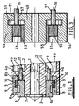
- FIG. 2 illustrates a cross-section through a turbocharger having a variable geometry turbine and incorporating a modification of the actuator of Figure 1.
- the illustrated turbocharger comprises a turbine wheel 20 and a compressor wheel 21 mounted to opposite ends of a turbocharger shaft 22.
- the turbine wheel 20 rotates within a turbine housing 23 and the compressor wheel 21 rotates within a compressor housing 24.
- the shaft 22 passes through a bearing housing 25 which interconnects the turbine and compressor housings 23 and 24.
- the bearing housing has a central portion which houses journal bearing assemblies 26 and 27 located towards the compressor and turbine ends of the bearing housing respectively.
- the compressor end of the bearing housing 25 itself houses a thrust bearing/oil seal assembly 28 and terminates in a radially extending diffuser section 29 which forms part of the compressor housing.
- an oil seal arrangement 30 is provided at the turbine end of the turbocharger shaft 22 where it passes into the turbine housing 23. Details of the bearing and oil seal arrangements may be entirely conventional and will not be described further.
- the bearing housing 25 has an outer generally cylindrical wall 31 and an inner generally cylindrical portion 32 defining an annular actuator cavity 33 and nozzle ring cavity 34 therebetween (corresponding to the cavity portions 4a and 4b of Figure 1).
- An axially moveable nozzle ring 35 is located within the cavity 34 and provides an annular wall 35a which defines one side of an annular turbine inlet passage 36.
- the opposing side of the inlet passage 36 is defined by a shroud plate 37 which covers an annular cavity 38 provided in the turbine housing 23.
- the nozzle ring 35 has inner and outer axially extending annular portions 35b and 35c which are sealed with respect to the bearing housing by inner and outer seal rings 39.
- the nozzle ring 35 supports a circumferential array of vanes 40 which extend across the turbine inlet 36 and through slots (not shown) provided in the shroud plate 37.
- the nozzle ring 35 is supported on a pair of push rods 41 which extend through tubular bearings 42, provided in a bearing housing radial wall 43 which separates the actuator cavity 33 from the nozzle ring cavity 34.
- nozzle ring arrangement is essentially conventional and incorporated in existing variable geometry turbine designs.
- present invention differs from the prior art is in the provision of an electric actuator located within the cavity 33, and moreover a linear actuator acting directly on the push rods 41 which support the nozzle ring 35.
- the actuator is a tubular linear electric reluctance motor comprising inner forcer ring 44 which is slidably mounted on an annular linear bearing 45 for axial movement within the cavity 33.
- the push rods 41 are secured to the ring 44 by way of respective fixing bolts 41a which extend through radially outwardly projecting annular portions 44a and 44b provided at opposing axial ends of ring 44.
- Forcer ring 44 corresponds to inner ring 6 of Figure 1.
- Outer bearing housing wall 31 has a radially thickened portion 31a adjacent radial wall 43 which defines an inner radial shoulder 46 within actuator cavity 33.
- An annular electrical coil member 47 is disposed within the outer bearing housing wall 31 adjacent the annular housing shoulder 46 and is secured axially by a ring 48.
- the radially thickened portion 31a of the bearing housing wall defining the annular shoulder 46, the ring 48, and that portion of the outer bearing housing wall 31 extending therebetween, correspond to the outer ring 8 of Figure 1, and together with electric coil 47 form the stator of the actuator.
- Movement and positional control of the nozzle ring 35 is achieved by providing a controlled voltage to the electrical coil 47 to generate a current therein which produces a magnetic flux which flows through the outer bearing housing wall 31, 31a and ring 48, and through the inner forcer ring 44, thereby exerting an axial force on the forcer ring 44, which in turn acts on the nozzle ring 35 via the push rods 41.
- variable geometry mechanism including the nozzle ring and its manner of mounting and movement, may vary from that shown.
- actuator could be applied to other forms of variable geometry mechanism.
- an appropriate stator ring (configured similar to that shown in Figure 1) could be fixed in position within the bearing housing wall of the turbocharger of Figure 2.
- the configuration, and location, of the push rods 41, or similar links to the nozzle ring may vary.
- stator is the radially outer component of the linear motor
- this arrangement could be reversed by providing a movable radially outer forcer ring and a fixed radially inner stator. Operation will otherwise be the same as that described above.
- this is an axial cross section through part of a turbocharger bearing housing corresponding to that part of the bearing housing shown schematically in Figure 1.
- the bearing housing comprises a cylindrical inner wall 49 and cylindrical outer wall 50 defining an annular actuator cavity 51 therebetween.
- radial housing wall 51 which defines one end of the cavity 51 is an end wall of the bearing housing rather than an intermediate wall.
- the variable geometry components (not shown) will be located within the turbine housing to the right of wall 52 as shown in Figure 3 (a similar modification can be applied to the embodiment illustrated schematically in Figure 1). Whether or not the variable geometry components are located in the bearing housing or turbine housing is largely irrelevant to operation of the present invention.
- An annular electric coil carrying forcer 53 is slidably mounted within the cavity 49 between a radially thickened portion 54 of the bearing housing outer wall 50, and an inner annular magnet 55 which is mounted around the inner bearing housing wall 49.
- the magnet 55 is a permanent magnet producing a radial magnetic flux which forms a magnetic circuit through the inner, outer and annular housing wall portions 50,52,54 (which are thus preferably fabricated from iron or other material with higher magnetic permeability).
- Axially extending push rods 56 extend from the forcer 53 through respective apertures 57 through the bearing housing end wall 52 to act on the variable geometry mechanism (not shown).
- the magnetic coil of forcer 53 is wound so that the conductors are largely perpendicular to the magnetic flux in the cavity.
- application of an AC voltage to the coil thus causing a varying current to flow through the coil, generates an electromagnetic force (through the Lorentz effect) which moves the forcer 53 axially within the cavity (essentially a brushless AC motor). Movement of the coil effects movement of the variable geometry mechanism via the push rods 57.
- the force applied to the coil, and thus the movement and position of the forcer 53 can be accurately controlled by appropriate control of the voltage and hence current applied to the coil.
Abstract
Description
- The present invention relates to a variable geometry turbine, and in particular the turbine of a turbocharger for an internal combustion engine.
- Turbochargers are well known devices for supplying air to the intake of an internal combustion engine at pressures above atmospheric (boost pressures). A conventional turbocharger essentially comprises an exhaust gas driven turbine wheel mounted on a rotatable shaft within a turbine housing. Rotation of the turbine wheel rotates a compressor wheel mounted on the other end of the shaft within a compressor housing. The compressor wheel delivers compressed air to the engine intake manifold. The turbocharger shaft is conventionally supported by journal and thrust bearings, including appropriate lubricating systems, located within a central bearing housing connected between the turbine and compressor wheel housing.
- In known turbochargers, the turbine stage comprises a turbine chamber within which the turbine wheel is mounted, an annular inlet passageway arranged around the turbine chamber, an inlet arranged around the inlet passageway, and an outlet passageway extending from the turbine chamber. The passageways and chambers communicate such that pressurised exhaust gas admitted to the inlet chamber flows through the inlet passageway to the outlet passageway via the turbine chamber and rotates the turbine wheel.
- Turbines may be of a fixed or variable geometry type. Variable geometry turbines differ from fixed geometry turbines in that the size of the inlet passageway can be varied to optimise gas flow velocities over a range of mass flow rates so that the power output of the turbine can be varied to suite varying engine demands. One common type of variable geometry turbine has vanes which extend into the inlet passageway and which can be pivoted to alter the effective cross-sectional area available for incoming gas, as well as the angle of approach of the gas to the turbine wheel. Such arrangements are generally referred to as swing vane variable geometry turbines. Typically each vane is pivotable about its own axis, and all vanes can be pivoted in unison by operation of an actuating mechanism linked to each of the vanes, often by a ring referred to as a unison ring.
- In another common type of variable geometry turbine, one wall of the inlet passageway is defined by a moveable wall member, generally referred to as a nozzle ring. The position of the nozzle ring relative to a facing wall of the inlet passageway is adjustable to control the width of the inlet passageway. For instance, as gas flowing through the turbine decreases the inlet passageway width may also be decreased to maintain gas velocity and optimise turbine output. Typically the nozzle ring is provided with vanes which extend into the inlet passageway and through slots provided on the facing wall of the inlet passageway to accommodate movement of the moveable nozzle ring. Alternatively, vanes may extend from a fixed wall through slots provided in the nozzle ring. The nozzle ring is generally supported on rods extending parallel to the axis of rotation of the turbine wheel and is moved by an actuator which axially displaces the rods.
- Various forms of actuator are known for use with variable geometry turbines, including pneumatic, hydraulic and electric actuators, mounted externally of the turbocharger and connected to the variable geometry system via appropriate linkages. For instance, known electric actuators comprise an electric motor mounted to the turbocharger housing and connected via a gear and mechanical linkage to movable elements of the variable geometry system. Such electric actuator systems have a number of disadvantages. For instance, the positional accuracy of the actuator is compromised by manufacturing tolerances and thermal expansion of the mechanical gear-train and linkage components. Moreover, the transient controllability (e.g. response time etc) of the actuator may be limited by backlash and hysteresis in the mechanical gear train and linkage.
- It is an object of the present invention to obviate or mitigate the above disadvantages.
- According to the present invention there is provided a variable geometry turbocharger comprising:
- a turbine wheel mounted within a turbine housing on one end of a turbocharger shaft for rotation about a turbocharger axis, the turbine housing defining an annular turbine inlet around the turbine wheel;
- a compressor wheel mounted within a compressor housing on the other end of said turbocharger shaft for rotation with the turbine wheel about said axis;
- turbocharger shaft bearing assemblies located within a bearing housing connected between the turbine housing and the compressor housing;
- a variable geometry mechanism for varying the size of the annular turbine inlet; and
- an electric motor for actuating the variable geometry mechanism; wherein the electric motor is a tubular linear electric motor comprising a fixed annular stator ring and an axially moveable annular forcer ring, arranged coaxially about said turbocharger axis with movement of the forcer ring effecting adjustment of the variable geometry mechanism.
-
- The annular linear motor is a particularly compact arrangement which can readily be incorporated in the turbocharger. In particular, in preferred embodiments of the invention the motor is located within the bearing housing, for instance between inner and outer bearing housing walls. In such embodiments of the invention the actuator motor is protected from accidental damage or tampering. In addition, avoiding mounting actuator components externally to the turbine housing increases flexibility of installation of the turbocharger in an engine environment. This particular assembly is also robust in construction and relatively simple to manufacture and assemble. Cooling is also readily provided by the turbochargers normal water and oil supply systems. In addition, location of the actuator motor relatively close to the variable geometry mechanism improves positional accuracy in control of the variable geometry mechanism, with produced dimensional tolerances in linkages between the two. This in turn improves transient controllability through reduced backlash and hysteresis in the linkage.
- Various forms of the new electric motor may be used, including reluctance motors and motor arrangements conventionally employed in linear stepper and servo motors (such as brushless AC arrangements).
- Other preferred and advantageous features of the invention will be apparent from the following description of embodiments of the invention.
- Specific embodiments of the present invention will now be described, by way of example only, with reference to the accompanying drawings, in which:
- Figure 1 is a schematic illustration of a turbocharger bearing housing and variable geometry actuating system in accordance with a first embodiment of the present invention;
- Figure 2 is an axial cross-section through a turbocharger including a modification of the variable geometry actuating system of Figure 1; and
- Figure 3 is a schematic illustration of a turbocharger bearing housing and variable geometry turbine actuating system in accordance with a second embodiment of the present invention.
-
- Referring to Figure 1, this schematically illustrates a radial section through part of a turbocharger bearing housing incorporating an electric actuator for a variable geometry turbine in accordance with the present invention. The axis of the turbocharger is indicated by dotted line 1. In a completed turbocharger a turbocharger shaft will extend through the bearing housing along the axis 1, the turbine being located to the right of Figure 1 and the compressor being located to the left.
- The bearing housing comprises a cylindrical
inner housing wall 2 and cylindricalouter housing wall 3 defining an annular cavity therebetween. The annular cavity is separated intoaxial portions housing wall 5 which extends radially between the inner andouter housing walls cavity portion 4b houses a variable geometry turbine nozzle arrangement (not shown) which is moveable to vary the geometry of a turbine inlet (not shown).Annular cavity portion 4a houses an electric actuator for the variable geometry system in accordance with the present invention. - The actuator is essentially a tubular linear electric motor in which the forcer (moving member) comprises an inner forcer ring 6 of iron (or other appropriate ferromagnetic material) slidably mounted on a cylindrical linear bearing 7. As shown in Figure 1, in radial cross-section the forcer ring 6 is generally C shaped with radially outwardly extending
annular portions housing wall 3, adjacent theradial housing wall 5.Stator ring 8 is also generally C shaped in radial cross-section, but in this case the radial extendingportions annular channel 10 defined between radially extendingportions stator ring 8. Thecoil 9 may be encapsulated within an epoxy compound to improve mechanical stiffness and thermal conductivity. - Axially oriented push rods 11 (at least two) extend from the forcer ring 6 at circumferentially spaced positions and extend through
respective apertures 12 in theannular housing wall 5 and intocavity portion 4b where they act upon the moveable nozzle member (not shown). - Supply of an electric current to the
coil 10 generates magnetic flux which passes through both the forcer andstator rings 6 and 8. The action of the magnetic flux exerts a force tending to align radially extendingportions portions stator ring 8. This is a result of the well known reluctance effect (the forcer ring is magnetised by the magnetic field generated by the coil and is often referred to as a reluctance magnet). Since thestator ring 8 is fixed in position, the force generated acts to move the inner forcer ring 6 axially along the bearing housing. The magnitude of the motive force can be controlled by controlling the magnitude of the current flowing through the coil (by appropriate control of the mean voltage level applied to the coil). This enables precise control over the axial positioning of the inner forcer ring 6, and hence of the geometry of the turbine via thepush rods 11 which act on the variable geometry mechanism (e.g. moving nozzle ring). - Figure 2 illustrates a cross-section through a turbocharger having a variable geometry turbine and incorporating a modification of the actuator of Figure 1. The illustrated turbocharger comprises a
turbine wheel 20 and acompressor wheel 21 mounted to opposite ends of aturbocharger shaft 22. Theturbine wheel 20 rotates within aturbine housing 23 and thecompressor wheel 21 rotates within acompressor housing 24. Between theturbine wheel 20 andcompressor wheel 21 theshaft 22 passes through a bearinghousing 25 which interconnects the turbine andcompressor housings journal bearing assemblies 26 and 27 located towards the compressor and turbine ends of the bearing housing respectively. The compressor end of the bearinghousing 25 itself houses a thrust bearing/oil seal assembly 28 and terminates in a radially extendingdiffuser section 29 which forms part of the compressor housing. Similarly, anoil seal arrangement 30 is provided at the turbine end of theturbocharger shaft 22 where it passes into theturbine housing 23. Details of the bearing and oil seal arrangements may be entirely conventional and will not be described further. - The bearing
housing 25 has an outer generallycylindrical wall 31 and an inner generally cylindrical portion 32 defining anannular actuator cavity 33 andnozzle ring cavity 34 therebetween (corresponding to thecavity portions cavity 34 and provides anannular wall 35a which defines one side of an annularturbine inlet passage 36. The opposing side of theinlet passage 36 is defined by ashroud plate 37 which covers anannular cavity 38 provided in theturbine housing 23. The nozzle ring 35 has inner and outer axially extendingannular portions 35b and 35c which are sealed with respect to the bearing housing by inner and outer seal rings 39. The nozzle ring 35 supports a circumferential array ofvanes 40 which extend across theturbine inlet 36 and through slots (not shown) provided in theshroud plate 37. The nozzle ring 35 is supported on a pair of push rods 41 which extend throughtubular bearings 42, provided in a bearing housingradial wall 43 which separates theactuator cavity 33 from thenozzle ring cavity 34. - The above described nozzle ring arrangement is essentially conventional and incorporated in existing variable geometry turbine designs. Where the present invention differs from the prior art is in the provision of an electric actuator located within the
cavity 33, and moreover a linear actuator acting directly on the push rods 41 which support the nozzle ring 35. - In accordance with the present invention the actuator is a tubular linear electric reluctance motor comprising
inner forcer ring 44 which is slidably mounted on an annularlinear bearing 45 for axial movement within thecavity 33. The push rods 41 are secured to thering 44 by way of respective fixingbolts 41a which extend through radially outwardly projecting annular portions 44a and 44b provided at opposing axial ends ofring 44.Forcer ring 44 corresponds to inner ring 6 of Figure 1. - Outer bearing
housing wall 31 has a radially thickened portion 31a adjacentradial wall 43 which defines an inner radial shoulder 46 withinactuator cavity 33. An annularelectrical coil member 47 is disposed within the outer bearinghousing wall 31 adjacent the annular housing shoulder 46 and is secured axially by aring 48. Together, the radially thickened portion 31a of the bearing housing wall defining the annular shoulder 46, thering 48, and that portion of the outer bearinghousing wall 31 extending therebetween, correspond to theouter ring 8 of Figure 1, and together withelectric coil 47 form the stator of the actuator. - Movement and positional control of the nozzle ring 35 is achieved by providing a controlled voltage to the
electrical coil 47 to generate a current therein which produces a magnetic flux which flows through the outer bearinghousing wall 31, 31a andring 48, and through theinner forcer ring 44, thereby exerting an axial force on theforcer ring 44, which in turn acts on the nozzle ring 35 via the push rods 41. - It will be appreciated that the detail of the variable geometry mechanism, including the nozzle ring and its manner of mounting and movement, may vary from that shown. Moreover, it will be appreciated that the actuator could be applied to other forms of variable geometry mechanism.
- It will also be appreciated that details of the particular configuration of the components of the electric actuator may vary from those shown. For instance, rather than providing the outer bearing housing wall with an enlarged radial portion defining an annular shoulder to form part of the motor stator, an appropriate stator ring (configured similar to that shown in Figure 1) could be fixed in position within the bearing housing wall of the turbocharger of Figure 2.
- Similarly, the configuration, and location, of the push rods 41, or similar links to the nozzle ring, may vary.
- It will also be appreciated that whereas with above described embodiments of the invention the stator is the radially outer component of the linear motor, this arrangement could be reversed by providing a movable radially outer forcer ring and a fixed radially inner stator. Operation will otherwise be the same as that described above.
- The above described embodiments of the invention take advantage of the reluctance effect to generate the necessary motor force. Alternative embodiments of the invention may however generate motor force through the Lorentz effect. Figure 3 is a schematic illustration of such an embodiment.
- Referring to Figure 3, this is an axial cross section through part of a turbocharger bearing housing corresponding to that part of the bearing housing shown schematically in Figure 1. Thus, the bearing housing comprises a cylindrical
inner wall 49 and cylindricalouter wall 50 defining anannular actuator cavity 51 therebetween. In this embodiment,radial housing wall 51 which defines one end of thecavity 51 is an end wall of the bearing housing rather than an intermediate wall. In this instance the variable geometry components (not shown) will be located within the turbine housing to the right ofwall 52 as shown in Figure 3 (a similar modification can be applied to the embodiment illustrated schematically in Figure 1). Whether or not the variable geometry components are located in the bearing housing or turbine housing is largely irrelevant to operation of the present invention. - An annular electric
coil carrying forcer 53 is slidably mounted within thecavity 49 between a radially thickenedportion 54 of the bearing housingouter wall 50, and an innerannular magnet 55 which is mounted around the inner bearinghousing wall 49. Themagnet 55 is a permanent magnet producing a radial magnetic flux which forms a magnetic circuit through the inner, outer and annularhousing wall portions push rods 56 extend from theforcer 53 throughrespective apertures 57 through the bearinghousing end wall 52 to act on the variable geometry mechanism (not shown). - The magnetic coil of
forcer 53 is wound so that the conductors are largely perpendicular to the magnetic flux in the cavity. As a result, application of an AC voltage to the coil, thus causing a varying current to flow through the coil, generates an electromagnetic force (through the Lorentz effect) which moves theforcer 53 axially within the cavity (essentially a brushless AC motor). Movement of the coil effects movement of the variable geometry mechanism via thepush rods 57. The force applied to the coil, and thus the movement and position of theforcer 53, can be accurately controlled by appropriate control of the voltage and hence current applied to the coil. - Although the nature of the force generation, and the detailed design of the actuator, of this embodiment of the invention differs from that of the embodiments of Figures 1 and 2, all embodiments share the common feature of a linear electric motor located within the bearing housing.
Claims (21)
- A variable geometry turbocharger comprising:wherein the electric motor is a tubular linear electric motor comprising a fixed annular stator ring and an axially moveable annular forcer ring, arranged coaxially about said turbocharger axis with movement of the forcer ring effecting adjustment of the variable geometry mechanism.a turbine wheel mounted within a turbine housing on one end of a turbocharger shaft for rotation about a turbocharger axis, the turbine housing defining an annular turbine inlet around the turbine wheel;a compressor wheel mounted within a compressor housing on the other end of said turbocharger shaft for rotation with the turbine wheel about said axis;turbocharger shaft bearing assemblies located within a bearing housing connected between the turbine housing and the compressor housing;a variable geometry mechanism for varying the size of the annular turbine inlet; andan electric motor for actuating the variable geometry mechanism;
- A turbocharger according to claim 1, wherein the electric motor is located within the bearing housing.
- A turbocharger according to claim 2, wherein the bearing housing comprises an inner annular wall surrounding said turbocharger shaft and said bearing assemblies, and an outer annular wall surrounding said inner annular wall, wherein the electric motor is located within an annular space defined between the inner and outer annular bearing housing walls.
- A turbocharger according to any preceding claim, wherein the stator ring comprises a conductive coil energisation of which generates a magnetic field which interacts with the forcer ring thereby exerting an axial force on the forcer ring.
- A turbocharger according to any one of claims 1 to 3, wherein the forcer ring comprises a conductive coil energisation of which generates a magnetic field which interacts with the stator ring thereby exerting an axial force on the forcer ring.
- A turbocharger according to claim 4, wherein the electric motor is a reluctance motor, said forcer ring comprising a reluctance magnet.
- A turbocharger according to claim 5, wherein the electric motor is a reluctance motor, said stator ring comprising a reluctance magnet.
- A turbocharger according to claim 6 or claim 7, wherein the stator ring and forcer ring each comprises one or more radially extending portions, the radially extending portions of the stator ring extending in a radial direction towards the radially extending portions of the forcer ring and vice versa, the reluctance force generated by energisation of said coil tending to bring radially extending portions of the stator ring and forcer ring into alignment with one another.
- A turbocharger according to claim 8, wherein said radially extending portions are annular.
- A turbocharger according to anyone of claims 7 to 9, wherein the coil is located between radially extending portions of the stator ring or forcer ring.
- A turbocharger according to any one of claims 7 to 10, wherein the stator ring and forcer ring are each generally "c" shaped in axially cross-section, each having two radially extending annular portions.
- A turbocharger according to claim 5, wherein the electric motor is a brushless AC motor wherein the forcer ring is a permanent magnet, said force being produced by the Lorentz effect.
- A turbocharger according to claim 6, wherein the electric motor is a brushless AC motor, the stator ring comprising a permanent magnet such that the force is produced by the Lorentz effect.
- A turbocharger according to any preceding claim, wherein the stator ring surrounds the forcer ring.
- A turbocharger according to any one of claims 1 to 13, wherein the forcer ring surrounds the stator ring.
- A turbocharger according to any preceding claim, wherein the stator ring is defined at least in part by a portion of the housing.
- A turbocharger according to any preceding claim, wherein the forcer ring slides on a linear bearing which lines the inner surface of the outer bearing housing wall or the outer surface of the inner bearing housing wall.
- A turbocharger according to any preceding claim, wherein a plurality of push rods extend from the forcer ring to the variable geometry mechanism.
- A turbocharger according to claim 18, wherein said push rods extend through respective bores in an annular housing wall separating said annular space in which the electric motor is located from the variable geometry mechanism.
- A turbocharger according to any preceding claim, wherein the variable geometry mechanism comprises an axially movable annular member, an annular portion of which defines one wall of said annular turbine inlet.
- A turbocharger according to any preceding claim, wherein the bearing housing is fabricated from a ferromagnetic metal such as iron or an iron based alloy.
Applications Claiming Priority (2)
| Application Number | Priority Date | Filing Date | Title |
|---|---|---|---|
| GB0228237 | 2002-12-04 | ||
| GBGB0228237.4A GB0228237D0 (en) | 2002-12-04 | 2002-12-04 | Variable geometry turbine |
Publications (3)
| Publication Number | Publication Date |
|---|---|
| EP1426580A2 true EP1426580A2 (en) | 2004-06-09 |
| EP1426580A3 EP1426580A3 (en) | 2004-11-10 |
| EP1426580B1 EP1426580B1 (en) | 2006-02-08 |
Family
ID=9949015
Family Applications (1)
| Application Number | Title | Priority Date | Filing Date |
|---|---|---|---|
| EP03257162A Expired - Fee Related EP1426580B1 (en) | 2002-12-04 | 2003-11-13 | Variable geometry turbine |
Country Status (4)
| Country | Link |
|---|---|
| US (1) | US7140849B2 (en) |
| EP (1) | EP1426580B1 (en) |
| DE (1) | DE60303486T2 (en) |
| GB (1) | GB0228237D0 (en) |
Cited By (2)
| Publication number | Priority date | Publication date | Assignee | Title |
|---|---|---|---|---|
| WO2006105804A1 (en) | 2005-04-04 | 2006-10-12 | Honeywell International Inc. | Variable flow turbocharger |
| GB2525240A (en) * | 2014-04-17 | 2015-10-21 | Cummins Ltd | Variable geometry turbine |
Families Citing this family (9)
| Publication number | Priority date | Publication date | Assignee | Title |
|---|---|---|---|---|
| US6895751B1 (en) * | 2004-03-08 | 2005-05-24 | Christopher Greentree | Vane control |
| DE102007017825A1 (en) * | 2007-04-16 | 2008-10-23 | Continental Automotive Gmbh | Compressor housing and turbocharger |
| WO2011084283A2 (en) * | 2009-12-17 | 2011-07-14 | Borgwarner Inc. | Turbocharger |
| CN102472298A (en) * | 2010-03-18 | 2012-05-23 | 丰田自动车株式会社 | Centrifugal compressor and turbo supercharger |
| CN102985659A (en) * | 2010-08-05 | 2013-03-20 | 博格华纳公司 | Exhaust-gas turbocharger |
| GB201015679D0 (en) * | 2010-09-20 | 2010-10-27 | Cummins Ltd | Variable geometry turbine |
| US9303561B2 (en) | 2012-06-20 | 2016-04-05 | Ford Global Technologies, Llc | Turbocharger compressor noise reduction system and method |
| US10337529B2 (en) | 2012-06-20 | 2019-07-02 | Ford Global Technologies, Llc | Turbocharger compressor noise reduction system and method |
| CN114320579B (en) * | 2021-12-23 | 2023-08-18 | 宋易霖 | Automatic regulation formula turbocharger |
Citations (5)
| Publication number | Priority date | Publication date | Assignee | Title |
|---|---|---|---|---|
| US4367626A (en) * | 1979-07-16 | 1983-01-11 | Schwartzman Everett H | Turbocharger systems |
| US4776168A (en) * | 1987-05-21 | 1988-10-11 | Woollenweber William E | Variable geometry turbocharger turbine |
| US4779423A (en) * | 1983-09-20 | 1988-10-25 | Holset Engineering Company Limited | Variable area turbocharger turbine and control system therefor |
| US6145314A (en) * | 1998-09-14 | 2000-11-14 | Turbodyne Systems, Inc. | Compressor wheels and magnet assemblies for internal combustion engine supercharging devices |
| DE19924228A1 (en) * | 1999-05-27 | 2000-12-07 | 3K Warner Turbosystems Gmbh | Multi-flow, adjustable exhaust gas turbocharger |
Family Cites Families (9)
| Publication number | Priority date | Publication date | Assignee | Title |
|---|---|---|---|---|
| DE2840201A1 (en) | 1978-09-15 | 1980-03-27 | Maschf Augsburg Nuernberg Ag | DEVICE FOR CHANGING THE INFLOW CROSS-SECTION OF THE TURBINE OF AN EXHAUST TURBOCHARGER |
| US4242040A (en) * | 1979-03-21 | 1980-12-30 | Rotoflow Corporation | Thrust adjusting means for nozzle clamp ring |
| FR2540557B1 (en) * | 1983-02-03 | 1987-03-20 | Onera (Off Nat Aerospatiale) | INTERNAL COMBUSTION ENGINE WITH TURBOCHARGER |
| US4808068A (en) * | 1986-10-28 | 1989-02-28 | Intertherm Investments, Inc. | Blower unloading device |
| GB9323340D0 (en) | 1993-11-11 | 1994-01-05 | Allied Signal Ltd | Turbochargers for internal combustion engines |
| US6256993B1 (en) * | 1995-07-28 | 2001-07-10 | Honeywell International, Inc. | Motor-assisted variable geometry turbocharging system |
| DE19901123A1 (en) * | 1999-01-14 | 2000-07-20 | Bosch Gmbh Robert | Controllable radial pump, especially for supplying coolant for car has adjuster connected with sleeve which can be slid over pump blades in axial direction |
| US6431823B1 (en) * | 2000-07-13 | 2002-08-13 | Yudko Slepoy | Centrifugal pump with variable capacity and pressure |
| JP4008404B2 (en) * | 2002-10-18 | 2007-11-14 | 三菱重工業株式会社 | Variable displacement exhaust turbocharger |
-
2002
- 2002-12-04 GB GBGB0228237.4A patent/GB0228237D0/en not_active Ceased
-
2003
- 2003-11-13 EP EP03257162A patent/EP1426580B1/en not_active Expired - Fee Related
- 2003-11-13 DE DE60303486T patent/DE60303486T2/en not_active Expired - Lifetime
- 2003-11-21 US US10/719,778 patent/US7140849B2/en active Active
Patent Citations (5)
| Publication number | Priority date | Publication date | Assignee | Title |
|---|---|---|---|---|
| US4367626A (en) * | 1979-07-16 | 1983-01-11 | Schwartzman Everett H | Turbocharger systems |
| US4779423A (en) * | 1983-09-20 | 1988-10-25 | Holset Engineering Company Limited | Variable area turbocharger turbine and control system therefor |
| US4776168A (en) * | 1987-05-21 | 1988-10-11 | Woollenweber William E | Variable geometry turbocharger turbine |
| US6145314A (en) * | 1998-09-14 | 2000-11-14 | Turbodyne Systems, Inc. | Compressor wheels and magnet assemblies for internal combustion engine supercharging devices |
| DE19924228A1 (en) * | 1999-05-27 | 2000-12-07 | 3K Warner Turbosystems Gmbh | Multi-flow, adjustable exhaust gas turbocharger |
Cited By (3)
| Publication number | Priority date | Publication date | Assignee | Title |
|---|---|---|---|---|
| WO2006105804A1 (en) | 2005-04-04 | 2006-10-12 | Honeywell International Inc. | Variable flow turbocharger |
| GB2525240A (en) * | 2014-04-17 | 2015-10-21 | Cummins Ltd | Variable geometry turbine |
| GB2525240B (en) * | 2014-04-17 | 2020-08-05 | Cummins Ltd | Variable geometry turbine |
Also Published As
| Publication number | Publication date |
|---|---|
| GB0228237D0 (en) | 2003-01-08 |
| EP1426580A3 (en) | 2004-11-10 |
| DE60303486D1 (en) | 2006-04-20 |
| DE60303486T2 (en) | 2006-10-26 |
| US7140849B2 (en) | 2006-11-28 |
| EP1426580B1 (en) | 2006-02-08 |
| US20040247462A1 (en) | 2004-12-09 |
Similar Documents
| Publication | Publication Date | Title |
|---|---|---|
| EP1426580B1 (en) | Variable geometry turbine | |
| EP1443189B1 (en) | Electric motor assisted turbocharger | |
| EP3551892B1 (en) | Compressor with variable compressor inlet | |
| KR101586821B1 (en) | Simplified variable geometry turbocharger with vane rings | |
| EP2247838B1 (en) | Supercharger arrangement for a piston engine | |
| CA2233998C (en) | Rotodynamic machine for the forwarding of a fluid | |
| CN112969844B (en) | Fan module for an aircraft turbine engine equipped with an electric motor | |
| KR20140124421A (en) | Multi-segment turbocharger bearing housing and methods therefor | |
| WO2008149060A2 (en) | Turbocharger | |
| US4496868A (en) | Electrical machine | |
| US20130164157A1 (en) | Generator arrangement | |
| JP2011509374A (en) | Turbocharger device for piston engine | |
| GB2497113A (en) | Turbocharger arrangement including a generator | |
| CN111457009A (en) | Active magnetic bearing device | |
| US9322478B2 (en) | Seal system and method for rotary machine | |
| US8133003B2 (en) | Magnetic adjustment of turbomachinery components | |
| KR100261003B1 (en) | Steam turbine | |
| EP3937350A1 (en) | Dual rotor electric machine | |
| US20190097479A1 (en) | Permanent magnet electrical machine | |
| EP2677133B1 (en) | Turbocharger embedding an electrical machine with a dc coil | |
| WO2009153546A2 (en) | Variable geometry turbine | |
| EP4191836A2 (en) | Additive manufacturing of a pump impeller including a rotor of an electric motor | |
| FI129201B (en) | Generator | |
| EP2677640B1 (en) | Turbocharger embedding an electrical machine with permanent magnets | |
| CN102077447B (en) | Linear actuator, in particular for adjusting the flaps in motor vehicle turbochargers |
Legal Events
| Date | Code | Title | Description |
|---|---|---|---|
| PUAI | Public reference made under article 153(3) epc to a published international application that has entered the european phase |
Free format text: ORIGINAL CODE: 0009012 |
|
| AK | Designated contracting states |
Kind code of ref document: A2 Designated state(s): AT BE BG CH CY CZ DE DK EE ES FI FR GB GR HU IE IT LI LU MC NL PT RO SE SI SK TR |
|
| AX | Request for extension of the european patent |
Extension state: AL LT LV MK |
|
| PUAL | Search report despatched |
Free format text: ORIGINAL CODE: 0009013 |
|
| AK | Designated contracting states |
Kind code of ref document: A3 Designated state(s): AT BE BG CH CY CZ DE DK EE ES FI FR GB GR HU IE IT LI LU MC NL PT RO SE SI SK TR |
|
| AX | Request for extension of the european patent |
Extension state: AL LT LV MK |
|
| 17P | Request for examination filed |
Effective date: 20050330 |
|
| GRAP | Despatch of communication of intention to grant a patent |
Free format text: ORIGINAL CODE: EPIDOSNIGR1 |
|
| AKX | Designation fees paid |
Designated state(s): DE FR GB |
|
| RBV | Designated contracting states (corrected) |
Designated state(s): DE FR GB |
|
| GRAS | Grant fee paid |
Free format text: ORIGINAL CODE: EPIDOSNIGR3 |
|
| GRAA | (expected) grant |
Free format text: ORIGINAL CODE: 0009210 |
|
| AK | Designated contracting states |
Kind code of ref document: B1 Designated state(s): DE FR GB |
|
| REG | Reference to a national code |
Ref country code: GB Ref legal event code: FG4D |
|
| REF | Corresponds to: |
Ref document number: 60303486 Country of ref document: DE Date of ref document: 20060420 Kind code of ref document: P |
|
| ET | Fr: translation filed | ||
| PLBE | No opposition filed within time limit |
Free format text: ORIGINAL CODE: 0009261 |
|
| STAA | Information on the status of an ep patent application or granted ep patent |
Free format text: STATUS: NO OPPOSITION FILED WITHIN TIME LIMIT |
|
| 26N | No opposition filed |
Effective date: 20061109 |
|
| REG | Reference to a national code |
Ref country code: FR Ref legal event code: PLFP Year of fee payment: 13 |
|
| REG | Reference to a national code |
Ref country code: FR Ref legal event code: PLFP Year of fee payment: 14 |
|
| REG | Reference to a national code |
Ref country code: FR Ref legal event code: PLFP Year of fee payment: 15 |
|
| PGFP | Annual fee paid to national office [announced via postgrant information from national office to epo] |
Ref country code: DE Payment date: 20181128 Year of fee payment: 16 |
|
| PGFP | Annual fee paid to national office [announced via postgrant information from national office to epo] |
Ref country code: FR Payment date: 20181127 Year of fee payment: 16 Ref country code: GB Payment date: 20181127 Year of fee payment: 16 |
|
| REG | Reference to a national code |
Ref country code: DE Ref legal event code: R119 Ref document number: 60303486 Country of ref document: DE |
|
| GBPC | Gb: european patent ceased through non-payment of renewal fee |
Effective date: 20191113 |
|
| PG25 | Lapsed in a contracting state [announced via postgrant information from national office to epo] |
Ref country code: FR Free format text: LAPSE BECAUSE OF NON-PAYMENT OF DUE FEES Effective date: 20191130 Ref country code: DE Free format text: LAPSE BECAUSE OF NON-PAYMENT OF DUE FEES Effective date: 20200603 Ref country code: GB Free format text: LAPSE BECAUSE OF NON-PAYMENT OF DUE FEES Effective date: 20191113 |
|
| P01 | Opt-out of the competence of the unified patent court (upc) registered |
Effective date: 20230510 |