EP1426576A2 - Tank/manifold for internally mounted radial flow intercooler for a combustion air charger - Google Patents
Tank/manifold for internally mounted radial flow intercooler for a combustion air charger Download PDFInfo
- Publication number
- EP1426576A2 EP1426576A2 EP03028152A EP03028152A EP1426576A2 EP 1426576 A2 EP1426576 A2 EP 1426576A2 EP 03028152 A EP03028152 A EP 03028152A EP 03028152 A EP03028152 A EP 03028152A EP 1426576 A2 EP1426576 A2 EP 1426576A2
- Authority
- EP
- European Patent Office
- Prior art keywords
- walls
- radially
- header plate
- housing
- heat exchanger
- Prior art date
- Legal status (The legal status is an assumption and is not a legal conclusion. Google has not performed a legal analysis and makes no representation as to the accuracy of the status listed.)
- Granted
Links
Images



Classifications
-
- F—MECHANICAL ENGINEERING; LIGHTING; HEATING; WEAPONS; BLASTING
- F28—HEAT EXCHANGE IN GENERAL
- F28D—HEAT-EXCHANGE APPARATUS, NOT PROVIDED FOR IN ANOTHER SUBCLASS, IN WHICH THE HEAT-EXCHANGE MEDIA DO NOT COME INTO DIRECT CONTACT
- F28D1/00—Heat-exchange apparatus having stationary conduit assemblies for one heat-exchange medium only, the media being in contact with different sides of the conduit wall, in which the other heat-exchange medium is a large body of fluid, e.g. domestic or motor car radiators
- F28D1/02—Heat-exchange apparatus having stationary conduit assemblies for one heat-exchange medium only, the media being in contact with different sides of the conduit wall, in which the other heat-exchange medium is a large body of fluid, e.g. domestic or motor car radiators with heat-exchange conduits immersed in the body of fluid
- F28D1/04—Heat-exchange apparatus having stationary conduit assemblies for one heat-exchange medium only, the media being in contact with different sides of the conduit wall, in which the other heat-exchange medium is a large body of fluid, e.g. domestic or motor car radiators with heat-exchange conduits immersed in the body of fluid with tubular conduits
- F28D1/053—Heat-exchange apparatus having stationary conduit assemblies for one heat-exchange medium only, the media being in contact with different sides of the conduit wall, in which the other heat-exchange medium is a large body of fluid, e.g. domestic or motor car radiators with heat-exchange conduits immersed in the body of fluid with tubular conduits the conduits being straight
- F28D1/0535—Heat-exchange apparatus having stationary conduit assemblies for one heat-exchange medium only, the media being in contact with different sides of the conduit wall, in which the other heat-exchange medium is a large body of fluid, e.g. domestic or motor car radiators with heat-exchange conduits immersed in the body of fluid with tubular conduits the conduits being straight the conduits having a non-circular cross-section
- F28D1/05366—Assemblies of conduits connected to common headers, e.g. core type radiators
- F28D1/05391—Assemblies of conduits connected to common headers, e.g. core type radiators with multiple rows of conduits or with multi-channel conduits combined with a particular flow pattern, e.g. multi-row multi-stage radiators
-
- F—MECHANICAL ENGINEERING; LIGHTING; HEATING; WEAPONS; BLASTING
- F02—COMBUSTION ENGINES; HOT-GAS OR COMBUSTION-PRODUCT ENGINE PLANTS
- F02B—INTERNAL-COMBUSTION PISTON ENGINES; COMBUSTION ENGINES IN GENERAL
- F02B29/00—Engines characterised by provision for charging or scavenging not provided for in groups F02B25/00, F02B27/00 or F02B33/00 - F02B39/00; Details thereof
- F02B29/04—Cooling of air intake supply
- F02B29/045—Constructional details of the heat exchangers, e.g. pipes, plates, ribs, insulation, materials, or manufacturing and assembly
- F02B29/0462—Liquid cooled heat exchangers
-
- F—MECHANICAL ENGINEERING; LIGHTING; HEATING; WEAPONS; BLASTING
- F02—COMBUSTION ENGINES; HOT-GAS OR COMBUSTION-PRODUCT ENGINE PLANTS
- F02B—INTERNAL-COMBUSTION PISTON ENGINES; COMBUSTION ENGINES IN GENERAL
- F02B29/00—Engines characterised by provision for charging or scavenging not provided for in groups F02B25/00, F02B27/00 or F02B33/00 - F02B39/00; Details thereof
- F02B29/04—Cooling of air intake supply
- F02B29/045—Constructional details of the heat exchangers, e.g. pipes, plates, ribs, insulation, materials, or manufacturing and assembly
- F02B29/0475—Constructional details of the heat exchangers, e.g. pipes, plates, ribs, insulation, materials, or manufacturing and assembly the intake air cooler being combined with another device, e.g. heater, valve, compressor, filter or EGR cooler, or being assembled on a special engine location
-
- F—MECHANICAL ENGINEERING; LIGHTING; HEATING; WEAPONS; BLASTING
- F02—COMBUSTION ENGINES; HOT-GAS OR COMBUSTION-PRODUCT ENGINE PLANTS
- F02B—INTERNAL-COMBUSTION PISTON ENGINES; COMBUSTION ENGINES IN GENERAL
- F02B37/00—Engines characterised by provision of pumps driven at least for part of the time by exhaust
- F02B37/013—Engines characterised by provision of pumps driven at least for part of the time by exhaust with exhaust-driven pumps arranged in series
-
- F—MECHANICAL ENGINEERING; LIGHTING; HEATING; WEAPONS; BLASTING
- F28—HEAT EXCHANGE IN GENERAL
- F28D—HEAT-EXCHANGE APPARATUS, NOT PROVIDED FOR IN ANOTHER SUBCLASS, IN WHICH THE HEAT-EXCHANGE MEDIA DO NOT COME INTO DIRECT CONTACT
- F28D1/00—Heat-exchange apparatus having stationary conduit assemblies for one heat-exchange medium only, the media being in contact with different sides of the conduit wall, in which the other heat-exchange medium is a large body of fluid, e.g. domestic or motor car radiators
- F28D1/02—Heat-exchange apparatus having stationary conduit assemblies for one heat-exchange medium only, the media being in contact with different sides of the conduit wall, in which the other heat-exchange medium is a large body of fluid, e.g. domestic or motor car radiators with heat-exchange conduits immersed in the body of fluid
- F28D1/04—Heat-exchange apparatus having stationary conduit assemblies for one heat-exchange medium only, the media being in contact with different sides of the conduit wall, in which the other heat-exchange medium is a large body of fluid, e.g. domestic or motor car radiators with heat-exchange conduits immersed in the body of fluid with tubular conduits
- F28D1/053—Heat-exchange apparatus having stationary conduit assemblies for one heat-exchange medium only, the media being in contact with different sides of the conduit wall, in which the other heat-exchange medium is a large body of fluid, e.g. domestic or motor car radiators with heat-exchange conduits immersed in the body of fluid with tubular conduits the conduits being straight
- F28D1/0535—Heat-exchange apparatus having stationary conduit assemblies for one heat-exchange medium only, the media being in contact with different sides of the conduit wall, in which the other heat-exchange medium is a large body of fluid, e.g. domestic or motor car radiators with heat-exchange conduits immersed in the body of fluid with tubular conduits the conduits being straight the conduits having a non-circular cross-section
- F28D1/05366—Assemblies of conduits connected to common headers, e.g. core type radiators
-
- F—MECHANICAL ENGINEERING; LIGHTING; HEATING; WEAPONS; BLASTING
- F28—HEAT EXCHANGE IN GENERAL
- F28F—DETAILS OF HEAT-EXCHANGE AND HEAT-TRANSFER APPARATUS, OF GENERAL APPLICATION
- F28F9/00—Casings; Header boxes; Auxiliary supports for elements; Auxiliary members within casings
- F28F9/02—Header boxes; End plates
- F28F9/0202—Header boxes having their inner space divided by partitions
-
- F—MECHANICAL ENGINEERING; LIGHTING; HEATING; WEAPONS; BLASTING
- F28—HEAT EXCHANGE IN GENERAL
- F28D—HEAT-EXCHANGE APPARATUS, NOT PROVIDED FOR IN ANOTHER SUBCLASS, IN WHICH THE HEAT-EXCHANGE MEDIA DO NOT COME INTO DIRECT CONTACT
- F28D1/00—Heat-exchange apparatus having stationary conduit assemblies for one heat-exchange medium only, the media being in contact with different sides of the conduit wall, in which the other heat-exchange medium is a large body of fluid, e.g. domestic or motor car radiators
- F28D1/02—Heat-exchange apparatus having stationary conduit assemblies for one heat-exchange medium only, the media being in contact with different sides of the conduit wall, in which the other heat-exchange medium is a large body of fluid, e.g. domestic or motor car radiators with heat-exchange conduits immersed in the body of fluid
- F28D2001/0253—Particular components
- F28D2001/026—Cores
- F28D2001/0273—Cores having special shape, e.g. curved, annular
-
- Y—GENERAL TAGGING OF NEW TECHNOLOGICAL DEVELOPMENTS; GENERAL TAGGING OF CROSS-SECTIONAL TECHNOLOGIES SPANNING OVER SEVERAL SECTIONS OF THE IPC; TECHNICAL SUBJECTS COVERED BY FORMER USPC CROSS-REFERENCE ART COLLECTIONS [XRACs] AND DIGESTS
- Y02—TECHNOLOGIES OR APPLICATIONS FOR MITIGATION OR ADAPTATION AGAINST CLIMATE CHANGE
- Y02T—CLIMATE CHANGE MITIGATION TECHNOLOGIES RELATED TO TRANSPORTATION
- Y02T10/00—Road transport of goods or passengers
- Y02T10/10—Internal combustion engine [ICE] based vehicles
- Y02T10/12—Improving ICE efficiencies
Definitions
- This invention relates to a heat exchanger used as an intercooler in a combustion air charging device such as a turbocharger or a supercharger for engines.
- Combustion air chargers such as turbochargers or superchargers
- engines particularly internal combustion engines, for many years.
- a turbocharger at least one rotary compressor wheel is driven by the exhaust of the engine.
- at least one rotary compressor wheel is driven mechanically, usually by the rotary output of the engine.
- the compressor wheel is employed to compress ambient air prior to its admission to the engine to support combustion therein. Because the air is compressed, a given volume thereof will have a greater mole content of oxygen than an otherwise equal of volume of air at ambient pressure. As a consequence, the additional oxygen permits the combustion of a greater quantity of fuel so that for a power plant of a given size, a greater power output may be derived as a result of the charging of the combustion air.
- intercoolers as mentioned previously have been employed to cool the air after it exits the combustion air charger (or a stage thereof) and prior to its admission to the engine so as to provide, for any given pressure, a maximum mole content of oxygen.
- the intercooler will be employed as a conventional, rectangular-shaped heat exchanger and is mounted side-by-side or to the front or rear of the usual heat exchanger employed for cooling engine coolant. While this sort of an arrangement adequately handles the cooling of the pressurized combustion air, it may have certain constraints in terms of size and the volume available in an engine compartment as, for example, in a vehicle, that houses both the engine and the various heat exchangers employed for cooling. It also may require extensive hose connections between the turbocharger, the intercooler and the engine combustion air inlet which necessarily require relatively large diameter hoses because of the low density of the combustion air and the consequent large volume thereof.
- the present invention is directed toward the provision of advantageous solutions to these problems in an intercooling heat exchanger that is intended to be located internally within the combustion air charger for an engine.
- an exemplary embodiment thereof achieves one or more of the above objects in a rotary machine that includes a rotatable shaft having at least one compressor wheel thereon and a two part housing containing the compressor wheel and having an inlet to the compressor wheel and an outlet.
- a heat exchanger is disposed in the housing and is located between the compressor wheel and the outlet.
- the heat exchanger includes a donut-shaped core having a gas flow path with a substantial radial extent, a header plate having radially inner and outer peripheries, and a gas inlet in fluid communication with the compressor wheel at a radially outer side of the core and a gas outlet in fluid communication with the housing outlet.
- a coolant flow path is provided in the heat exchanger in heat exchange relation with the gas flow path and has a substantial axial extent.
- the coolant flow has a radially inner section and a radially outer section which are connected so that coolant flows first through one and then the other.
- the heat exchanger includes a combined manifold and tank secured and sealed to a header plate forming one side of the core which includes walls defining first and second, axially spaced, side-by-side annular spaces separated by an annular baffle extending axially from one of the walls into a substantial abutment with the header plate between different radially spaced locations that separate the radially inner coolant flow path from the radially outer coolant flow path.
- the combined manifold and tank assembly is removably mounted to the housing in sandwiched relation between the parts of the housing.
- the tank assembly walls include first, second and third axially spaced walls, each having a central opening.
- the first wall is sealingly secured to, at its central opening, the header plate at the radially outer periphery thereof.
- the second wall at its central opening, mounts the baffle that engages the header plate between parts of the coolant flow path and the third wall, at its central opening, includes an annular, axially axial extension sealingly secured to the header plate at its radially inner periphery.
- the first, second and third walls and the first and second annular spaces defined thereby extend radially outward of the radially outer periphery of the header plate.
- Such an extension may be employed as a mounting flange for mounting the manifold and tank assembly between the two parts of the housing.
- the manifold and tank assembly has at least one first port opening to a space between the first and second walls and at least one second port opening to a space between the second and third walls.
- At least one of the ports is in an annular wall at the radially outer part of the manifold and tank assembly.
- the rotary compressor machine is a turbocharger or supercharger used in a combustion air charging system.
- turbochargers and superchargers are referred to herein as combustion air chargers and no limitation to either turbochargers or to superchargers is intended except insofar as expressly stated in the appended claims.
- the invention is susceptible to use as a rotary compressor machine in any of a variety of uses where it is desired to cool compressed air heated by a rotary compressor prior to its delivery to a point of use; and again, no limitation to a combustion air charging device or system is intended except as recited in the appended claims. With the foregoing in mind, attention is directed to Fig. 1.
- the exemplary embodiment of the invention is seen to include a housing, generally designated 10, formed of at least two separable sections, 12 and 14 respectively.
- the housing sections are joined at a circular interface (not shown) which then allows relative rotation between the sections 12 and 14 during the assembly process to accommodate spacial constraints and/or to speed assembly.
- Journalled within the housing 10 by any suitable bearings (not shown) is a rotary shaft 18.
- the rotary shaft mounts a first compressor wheel 20, a second compressor wheel 22 and turbine wheel 24 which, in turn, will be located within a housing (not shown).
- the turbine wheel 24 is driven by the exhaust from an internal combustion engine to drive the shaft 18.
- Spent exhaust is outletted from the turbine wheel 24 as indicated by an arrow 28.
- the housing 1 2 includes an ambient air inlet 30 while the housing 14 includes a compressed air outlet, schematically indicated by an arrow 32.
- the inlet 30 is to the inlet side of the compressor wheel 20 while the outlet 32 is from a volute, schematically illustrated at 34, on the outlet side of the compressor wheel 22.
- a heat exchanger is contained within the housings 12,14 where the two are joined together as indicated schematically by removable fasteners 38.
- the heat exchanger 36 is donut-shaped or ring-shaped and includes a radially outer cylindrical surface 40 which defines an air inlet for the passage of air through the heat exchanger 36.
- a radially inner cylindrical surface 42 forms an air outlet for the heat exchanger 36.
- the sides of the heat exchanger are provided with a manifold and tank, generally designated 44, on the side of the heat exchanger 36 facing the housing 14 and a redirecting header and tank, generally designated 46, on the side of the heat exchanger 36 within the housing 12.
- the manifold and tank 44 is provided with a coolant inlet schematically illustrated by an arrow 56 and a coolant outlet 58 schematically illustrated by an arrow.
- a coolant such as coolant for the internal combustion engine enters the turbocharger through the inlet 56 and is passed to a radially inner manifold and tank section 59 from which it flows into the core of the heat exchanger 36 at a radially inner part thereof to flow axially through the heat exchanger 36 to the reentrant header and tank 46 where its direction is reversed to flow through the radially outer part of the heat exchanger 36 back to a radially outer section 62 and then to the coolant outlet 58.
- This flow of coolant is indicated by arrow 64.
- Air flow through the turbocharger is as follows. Ambient air enters in the inlet 30 and passes to the inlet side of the compressor wheel 20. As the compressor wheel 20 is driven by the turbine wheel 24, the air is compressed and discharged at an elevated pressure on the radially outer periphery of the compressor wheel 20 as indicated by arrows 66.
- the compressed air continues to flow radially outwardly through an annular space 68 between the housing 12 and the heat exchanger 36 which is in part defined by the reentrant header and tank 46, a radial baffle 70 extending radially inwardly from the reentrant header and tank 46 and an axial baffle 72 which extends from the baffle 70 at its radially innermost part to mount on a part of the housing 1 2 (not shown) in adjacency to the turbine wheel 20.
- the radially outer side or periphery 40 of the heat exchanger 36 is spaced radially inwardly from the housings 12 and 14 allowing the air compressed by the turbine wheel 20 to be redirected as indicated by arrows 74 to enter the heat exchanger 36 at the radially outer periphery 40 thereof.
- the air then passes through the heat exchanger 36 in a radially inward direction and is cooled by the coolant that flows axially through the heat exchanger 36 as mentioned earlier.
- the cooled, compressed air is then discharged from the heat exchanger 36 as indicated by arrows 76 to the inlet side of the compressor wheel 22 whereat it is further compressed and then discharged into the volute 34 as indicated by arrows 78.
- This compressed air is then discharged as compressed combustion air to the internal engine to support combustion therein.
- additional cooling stages could be included between the compressor wheel 22 and the engine.
- the compressor wheel 22 can be omitted in which case the air being discharged from the radially inner side of periphery 42 of the heat .exchanger 36 could be discharged directly into the volute 34.
- Figs. 2-4 inclusive, the heat exchanger 36 and the manifold and tank 44 will be described in detail. It is initially noted that the heat exchanger 36 may conveniently be constructed as described and illustrated in the commonly assigned, copending application of Meshenky et al entitled “Internally Mounted Radial Flow Intercooler for a Combustion Air Charger", filed September 20, 2002, Serial No. 10/251,537, the entire disclosure of which is herein incorporated by reference.
- the housing 12 includes a radially outwardly directed peripheral flange 80.
- a similar flange 82 is disposed on the housing 14 and is of the same size as the flange 80.
- the manifold and tank 44 is sandwiched between the flanges 80 and 82 and aligned bores 84 in all three may receive threaded fasteners (not shown) for securing the manifold and tank 44 between the housing sections 12,14.
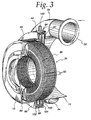
- the heat exchanger 36 is best illustrated in Figs. 3 and 4 and is seen to include, on each side thereof, a header 86,88, respectively.
- the header 86 forms part of the header and tank 46, the latter also including an annular tank 90 fitted to and sealed against the header 86.
- Extending between the headers 86 and 88 are a plurality of straight tubes 92 which are received in tube slots in the headers 86,88 and metallurgically bonded and sealed thereto.
- the tubes 92 are in two rows as may be seen in each of Figs. 3 and 4 with the inner row of tubes 92 defining the radially inner flow path referred to previously and the radially outer tubes 92 forming the radially outer flow path.
- the tank 90 provides for fluid communication between the tubes 92 of both rows.
- Fins (not numbered), which may be plate fins or serpentine fins, extend between the tubes 92 and serve to define, along with the headers 86,88, a gas flow path through which the compressed gas flows in the manner mentioned previously.
- the heat exchanger 36 may be formed in a single piece as illustrated in the drawings or may be formed of a plurality of arcuate segments that are fitted together to define an annular heat exchanger.
- the manifold and tank 44 is best understood from a consideration of Figs. 3 and 4. With reference to Fig. 4, it is seen that the same includes three radially extending walls 96, 98 and 100. The walls are axially spaced from one another to define first and second spaces 102 and 104. An annular, radially outer wall 106 connects the walls 96,98,100 together and includes the fastener receiving bores 84.
- Each of the walls 96,98,100 includes a central opening 110,112,114, respectively.
- the central openings 110, 112 and 114 are of progressively smaller diameter so that the wall 96, at its central opening 110, may be metallurgically bonded and sealed, as by brazing, to the header plate 88 at its radially outer periphery. Alternatively, the wall 96 may simply be removably sealed to the header plate 88.
- the wall 98 mounts an axially directed baffle 116 which extends axially into engagement with an imperforate region 118 of the header 88 located between the two rows of tubes 92 to form a gross seal thereat so as to segregate the two rows for providing the flow path described previously.
- the wall 100 at its central opening 114, includes an axial extension 120 which extends to the radially inner periphery of the heat exchanger 36, and specifically, the header 88 thereof to be bonded metallurgically and sealed thereto, or in the alternative, merely removably sealed thereto.
- the manifold and tank 44 and specifically, the annular outer wall 106 thereof, is provided with two ports (only one of which is shown in Fig. 3) and which is designated 122.
- the port 122 as shown extends to the space 104 to establish fluid communication therewith.
- a similar port (not shown) extends to the space 102 for the same purpose.
- multiple bores 128 forming ports may be provided to extend to the space and multiple bores 130 may be provided to extend to and serve as ports for the space 102.
- the walls 96,98,100 have a greater diametrical dimension than does the heat exchanger 36 or the housings 12 and 14, apart from the flanges 80,82.
- radially outer parts of the walls, together with the annular outer wall 106 serve as mounting flange to be received between the mounting flanges 80,82 as shown in Figs. 2 and 3.
- manifold and tank 44 provide the function of a tank in directing coolant to or collecting coolant from the rows of the tubes 92. It will also be appreciated that the same provides a manifold function in terms of distributing coolant coming to or from the source to the tank-like spaces that open to the header 88 as well. The same may be made relatively thin so that the size of the rotary machine is not unduly increased axially and may be employed with existing mounting flanges on the housings 12 and 14 for suitable mounting purposes.
- the heat exchanger 36 may be mounted only to the manifold and tank 44 allowing the side thereof including the tank 90 and the header plate 86 freedom of movement in the axial direction within the turbocharger to accommodate temperature changes and thereby minimize thermal stress that could result in undesirable fatigue of the parts.
- the construction is such that potential coolant leakage points within the machine are reduced to a minimum.
- diffuser vanes sometimes referred to as flow straighteners
- tank 46 and/or the manifold and tank 44 it may be desirable to thermally join diffuser vanes (sometimes referred to as flow straighteners) to the tank 46 and/or the manifold and tank 44 as more fully disclosed in commonly assigned Serial No. 10/256,863, filed September 27, 2002 in the name of Steven P. Meshenky, the entire disclosure of which is incorporated by reference.
- the geometric configuration is simple and thus easy to manufacture.
Landscapes
- Engineering & Computer Science (AREA)
- Mechanical Engineering (AREA)
- General Engineering & Computer Science (AREA)
- Physics & Mathematics (AREA)
- Thermal Sciences (AREA)
- Chemical & Material Sciences (AREA)
- Combustion & Propulsion (AREA)
- Supercharger (AREA)
- Heat-Exchange Devices With Radiators And Conduit Assemblies (AREA)
- Structures Of Non-Positive Displacement Pumps (AREA)
Abstract
Description
Claims (8)
- A rotary compressor machine including:a rotatable shaft having at least one compressor wheel mounted thereon;a housing formed of two separable parts with one part encompassing said at least one compressor wheel, said housing journalling said shaft, and having an inlet to said compressor wheel in said one part and an outlet in the other of said parts; anda donut-shaped heat exchanger within said housing one part and between said compressor wheel and said outlet and having radially inner and outer peripheries, one said periphery defining an inlet for receiving compressed gas from said compressor wheel and the other said periphery defining an outlet for discharging compressed gas toward said housing outlet, said heat exchanger including tube constructions defining coolant flow paths and having ends at a header plate, and characterized by the coolant flow paths being generally axial with first flow paths directing fluid away from said header plate and second flow paths returning the fluid to the header plate with said first and said second flow paths being grouped and opening to said header plate at different, radially spaced locations, and a combined manifold and tank sealed to said header plate including walls defining first and second, axially spaced, side-by-side annular spaces separated by an annular baffle extending axially from one of said walls into substantial abutment with said header plate between said different, radially spaced locations, said combined manifold and tank assembly being removably mounted to said housing in sandwiched relation between said first and second parts.
- The rotary compressor machine of claim 1 wherein said combined manifold and tank assembly walls include first, second and third axially spaced walls each having a central opening, said first wall being sealed to, at its central opening, said header plate at said radially outer periphery, said second wall, at its central opening, mounting said baffle, and said third wall, at its central opening, including an annular, axial extension sealed to said header plate at said radially inner periphery.
- The rotary compressor machine of claim 2 wherein said first, second and third walls and said first and second annular spaces extend radially outward of said radially outer periphery.
- The rotary compressor machine of claim 1 wherein said walls and said first and second annular spaces extend radially outward of said radially outer periphery.
- The rotary compressor machine of claim 1 wherein said housing, said compressor wheel and said shaft define a combustion air charger.
- A heat exchanger for installation in a two part housing of a rotary compressor machine for use as an intercooler, comprising a donut-shaped heat exchanger within said housing one part and between said compressor wheel and said outlet and having radially inner and outer peripheries, one said periphery defining an inlet for receiving compressed gas from said compressor wheel and the other said periphery defining an outlet for discharging compressed gas to said housing outlet, said heat exchanger including tube constructions defining coolant flow paths and having ends at a header plate, the coolant flow paths being generally axial with first flow path directly fluid away from said header plate and second flow paths returning the fluid to the header plate with said first and said second flow paths being grouped and opening to said header plate at different, radially spaced locations, and a combined manifold and tank secured and sealed to said header plate including walls defining first and second, axially spaced, side-by-side annular spaces separated by an annular baffle extending axially from one of said walls into substantial abutment with said header plate between said different, radially spaced locations, said combined manifold and tank assembly being removably mounted to said housing in sandwiched relation between said first and second parts.
- A heat exchanger for installation in a rotary compressor machine for use as an intercooler, comprising:a donut-shaped core having at least one row of axially extending tubes and ring-like header plates with radially inner and outer peripheries at each side of said row, said header plates having tube slots sealingly receiving the ends of the tubes in the row, said tubes defining radially inner and radially outer flow paths, and fins extending between said tubes;a tank sealingly fitted to one of said header plates oppositely of said tubes to interconnect said radially inner and outer flow paths thereat; anda combined manifold and tank sealingly fitted to the other of said headers oppositely of said tubes and including three axially spaced, radially extending walls, each having a central opening and each extending radially outward of the radially outer periphery of said core to terminate in a radially outer mounting flange;a first of said walls, at its central opening, being sealed to said other header at its radially outer periphery;a second of said walls, at its central opening, including an annular, axially extending baffle engaging said other header at a location between said radially inner and said radially outer flow paths; anda third of said walls, at its central opening, being sealed to said other header plate at its radially inner periphery;said first, second and third walls being joined at their radially outer ends by an annular wall;at least one first port opening to a space between said first and second walls; andat least one second port opening to a space between said second and third walls.
- The heat exchanger of claim 7 wherein at least one of said ports is in said annular wall.
Applications Claiming Priority (2)
| Application Number | Priority Date | Filing Date | Title |
|---|---|---|---|
| US313210 | 2002-12-06 | ||
| US10/313,210 US6929056B2 (en) | 2002-12-06 | 2002-12-06 | Tank manifold for internally mounted radial flow intercooler for a combustion air charger |
Publications (3)
| Publication Number | Publication Date |
|---|---|
| EP1426576A2 true EP1426576A2 (en) | 2004-06-09 |
| EP1426576A3 EP1426576A3 (en) | 2004-06-16 |
| EP1426576B1 EP1426576B1 (en) | 2008-07-23 |
Family
ID=32312284
Family Applications (1)
| Application Number | Title | Priority Date | Filing Date |
|---|---|---|---|
| EP03028152A Expired - Lifetime EP1426576B1 (en) | 2002-12-06 | 2003-12-08 | Tank/manifold for internally mounted radial flow intercooler for a combustion air charger |
Country Status (8)
| Country | Link |
|---|---|
| US (1) | US6929056B2 (en) |
| EP (1) | EP1426576B1 (en) |
| JP (1) | JP2004190674A (en) |
| BR (1) | BR0305276A (en) |
| CA (1) | CA2450393A1 (en) |
| DE (1) | DE60322327D1 (en) |
| MX (1) | MXPA03010710A (en) |
| RU (1) | RU2003135539A (en) |
Cited By (4)
| Publication number | Priority date | Publication date | Assignee | Title |
|---|---|---|---|---|
| WO2009073124A1 (en) * | 2007-11-30 | 2009-06-11 | Caterpillar Inc. | Annular intercooler having curved fins |
| GB2504829A (en) * | 2012-06-11 | 2014-02-12 | Jaguar Land Rover Ltd | Flow connector for a Boosted Internal Combustion Engine |
| AT516986B1 (en) * | 2015-03-26 | 2018-09-15 | Avl List Gmbh | MULTI-STAGE ABGASTURBOLADER |
| FR3115821A1 (en) * | 2020-11-05 | 2022-05-06 | Psa Automobiles Sa | PROPULSION AND HEAT RECOVERY SYSTEM FITTING A MOTOR VEHICLE |
Families Citing this family (17)
| Publication number | Priority date | Publication date | Assignee | Title |
|---|---|---|---|---|
| US7191769B2 (en) * | 2002-03-17 | 2007-03-20 | Man Steyr Ag | Internal combustion engine having two-stage exhaust-driven supercharger and charge air cooling between low pressure and high pressure compressors |
| KR100618056B1 (en) | 2004-08-17 | 2006-08-30 | 동환산업 주식회사 | Unit tube for fluid transfer and annular heater using the same |
| US20060275151A1 (en) * | 2005-06-01 | 2006-12-07 | Caterpillar Inc. | Pump and heat exchanger |
| US7584782B1 (en) * | 2006-08-28 | 2009-09-08 | Hamilton Sundstrand Corporation | Valve defining modulated and unmodulated flow paths |
| DE102007010123A1 (en) * | 2007-02-28 | 2008-09-04 | Behr Gmbh & Co. Kg | Charge-cooling device for a motor vehicle's internal combustion engine has heat-exchangers for high-pressure and low-pressure charge cooling with a coolant feed and coolant drain line |
| JP2008248865A (en) * | 2007-03-30 | 2008-10-16 | Fujitsu General Ltd | Injection-compatible two-stage rotary compressor and heat pump system |
| DE102007024633A1 (en) * | 2007-05-24 | 2008-11-27 | Behr Gmbh & Co. Kg | Multi-stage compressor unit with cooling device |
| US8393860B2 (en) * | 2007-12-13 | 2013-03-12 | Cameron International Corporation | Heat exchanger |
| EP2616679A2 (en) | 2010-09-16 | 2013-07-24 | Wilson Solarpower Corporation | Concentrated solar power generation using solar receivers |
| US9033648B2 (en) | 2010-12-24 | 2015-05-19 | Rolls-Royce North American Technologies, Inc. | Cooled gas turbine engine member |
| JP2012197684A (en) * | 2011-03-18 | 2012-10-18 | Mitsubishi Heavy Ind Ltd | Single-shaft two-stage supercharger |
| WO2014007791A1 (en) | 2011-05-11 | 2014-01-09 | Dresser-Rand Company | Compact compression system with integral heat exchangers |
| US8959913B2 (en) * | 2011-09-15 | 2015-02-24 | General Electric Company | Systems and apparatus for transferring fluid flow |
| CN118856636A (en) | 2012-03-21 | 2024-10-29 | 威尔逊太阳能公司 | Solar receivers, power generation systems, and heat storage and recovery systems |
| US20140027097A1 (en) * | 2012-07-30 | 2014-01-30 | Ian Alexandre Araujo De Barros | Heat Exchanger for an Intercooler and Water Extraction Apparatus |
| JP6668161B2 (en) * | 2016-05-11 | 2020-03-18 | 株式会社マーレ フィルターシステムズ | Turbocharger |
| AU2021248410B2 (en) | 2020-04-02 | 2025-03-13 | 247Solar, Inc. | Concentrated solar energy collection, thermal storage, and power generation systems and methods with optional supplemental fuel production |
Family Cites Families (33)
| Publication number | Priority date | Publication date | Assignee | Title |
|---|---|---|---|---|
| US1265650A (en) * | 1917-04-14 | 1918-05-07 | Escher Wyss Maschf Ag | Cooling device in multistage centrifugal compressors. |
| US1425855A (en) * | 1920-12-01 | 1922-08-15 | Graemiger Benjamin | Cooling device in multistage centrifugal compressors |
| US2384251A (en) | 1943-01-14 | 1945-09-04 | Wright Aeronautical Corp | Liquid cooled supercharger |
| US2474410A (en) | 1945-01-13 | 1949-06-28 | Sulzer Ag | Multistage compressor |
| US2650073A (en) * | 1949-06-25 | 1953-08-25 | Air Preheater | Combined regenerator and precooler for gas turbine cycles |
| DE1093040B (en) | 1955-10-31 | 1960-11-17 | Schweizerische Lokomotiv | Multi-stage centrifugal compressor with tube intercooler |
| US2925954A (en) * | 1956-03-29 | 1960-02-23 | Escher Wyss Ag | Compressor group with intercooler |
| US3014639A (en) * | 1957-09-06 | 1961-12-26 | Garrett Corp | High pressure air compressor |
| US3134536A (en) * | 1961-06-27 | 1964-05-26 | Ass Elect Ind | Intercoolers for gas compressors |
| CH416920A (en) | 1964-04-29 | 1966-07-15 | List Hans Dipl Ing Dr Dr H C P | Blower unit, in particular for exhaust gas turbocharging for internal combustion engines |
| CH466343A (en) | 1968-06-25 | 1968-12-15 | Saurer Ag Adolph | Cross-flow heat exchanger |
| US3811495A (en) * | 1970-10-26 | 1974-05-21 | Laing Nikolaus | Rotary heat exchangers in the form of turbines |
| US4125345A (en) * | 1974-09-20 | 1978-11-14 | Hitachi, Ltd. | Turbo-fluid device |
| US4062401A (en) | 1976-05-03 | 1977-12-13 | International Harvester Company | Toroidal multifluid segmented heat exchanger |
| US4373577A (en) | 1980-07-21 | 1983-02-15 | International Harvester Co. | Heat exchanger assembly |
| GB8322367D0 (en) | 1983-08-19 | 1983-09-21 | Secretary Trade Ind Brit | Regenerative turbo-machine |
| US4550775A (en) | 1983-10-21 | 1985-11-05 | American Standard Inc. | Compressor intercooler |
| US4706736A (en) | 1986-05-20 | 1987-11-17 | Technicon Instruments Corporation | Multi-zone heater arrangement for controlling the temperature of a flowing medium |
| US5077601A (en) | 1988-09-09 | 1991-12-31 | Hitachi, Ltd. | Cooling system for cooling an electronic device and heat radiation fin for use in the cooling system |
| JP2813914B2 (en) | 1990-04-04 | 1998-10-22 | 昭和アルミニウム株式会社 | Heat exchanger |
| US5078206A (en) | 1990-06-12 | 1992-01-07 | Goetz Jr Edward E | Tube and fin circular heat exchanger |
| US5172752A (en) | 1990-06-12 | 1992-12-22 | Goetz Jr Edward E | Curved heat exchanger with low frontal area tube passes |
| US5259444A (en) | 1990-11-05 | 1993-11-09 | Masachusetts Institute Of Technology | Heat exchanger containing a component capable of discontinuous movement |
| US5303770A (en) | 1993-06-04 | 1994-04-19 | Dierbeck Robert F | Modular heat exchanger |
| DE69421222T2 (en) | 1993-08-02 | 2000-06-08 | General Electric Co., Schenectady | Cooling unit |
| GB2291130B (en) | 1994-07-12 | 1998-09-30 | Rolls Royce Plc | A gas turbine engine |
| WO1998044305A1 (en) | 1997-04-02 | 1998-10-08 | Creare Inc. | Radial flow heat exchanger |
| US6430931B1 (en) | 1997-10-22 | 2002-08-13 | General Electric Company | Gas turbine in-line intercooler |
| US6173493B1 (en) | 1998-10-15 | 2001-01-16 | Robert F. Dierbeck | Modular heat exchanger and method of making |
| US6374612B1 (en) | 2000-09-21 | 2002-04-23 | Caterpillar Inc. | Interstage cooling of a multi-compressor turbocharger |
| DE10141490A1 (en) * | 2001-08-24 | 2003-03-13 | Behr Gmbh & Co | Radiator and method for cooling a medium |
| US6526751B1 (en) | 2001-12-17 | 2003-03-04 | Caterpillar Inc | Integrated turbocharger ejector intercooler with partial isothermal compression |
| US6764279B2 (en) * | 2002-09-27 | 2004-07-20 | Modine Manufacturing Company | Internally mounted radial flow intercooler for a rotary compressor machine |
-
2002
- 2002-12-06 US US10/313,210 patent/US6929056B2/en not_active Expired - Fee Related
-
2003
- 2003-11-24 CA CA002450393A patent/CA2450393A1/en not_active Abandoned
- 2003-11-24 MX MXPA03010710A patent/MXPA03010710A/en unknown
- 2003-11-26 BR BR0305276-1A patent/BR0305276A/en not_active Application Discontinuation
- 2003-12-05 RU RU2003135539/06A patent/RU2003135539A/en not_active Application Discontinuation
- 2003-12-05 JP JP2003407095A patent/JP2004190674A/en not_active Ceased
- 2003-12-08 DE DE60322327T patent/DE60322327D1/en not_active Expired - Fee Related
- 2003-12-08 EP EP03028152A patent/EP1426576B1/en not_active Expired - Lifetime
Cited By (6)
| Publication number | Priority date | Publication date | Assignee | Title |
|---|---|---|---|---|
| WO2009073124A1 (en) * | 2007-11-30 | 2009-06-11 | Caterpillar Inc. | Annular intercooler having curved fins |
| US8132408B2 (en) | 2007-11-30 | 2012-03-13 | Caterpillar Inc. | Annular intercooler having curved fins |
| GB2504829A (en) * | 2012-06-11 | 2014-02-12 | Jaguar Land Rover Ltd | Flow connector for a Boosted Internal Combustion Engine |
| GB2504829B (en) * | 2012-06-11 | 2015-07-22 | Jaguar Land Rover Ltd | Improvements in Air Handling for a Boosted Internal Combustion Engine |
| AT516986B1 (en) * | 2015-03-26 | 2018-09-15 | Avl List Gmbh | MULTI-STAGE ABGASTURBOLADER |
| FR3115821A1 (en) * | 2020-11-05 | 2022-05-06 | Psa Automobiles Sa | PROPULSION AND HEAT RECOVERY SYSTEM FITTING A MOTOR VEHICLE |
Also Published As
| Publication number | Publication date |
|---|---|
| MXPA03010710A (en) | 2004-06-16 |
| US20040107948A1 (en) | 2004-06-10 |
| DE60322327D1 (en) | 2008-09-04 |
| RU2003135539A (en) | 2005-05-10 |
| US6929056B2 (en) | 2005-08-16 |
| EP1426576A3 (en) | 2004-06-16 |
| BR0305276A (en) | 2004-08-31 |
| CA2450393A1 (en) | 2004-06-06 |
| EP1426576B1 (en) | 2008-07-23 |
| JP2004190674A (en) | 2004-07-08 |
Similar Documents
| Publication | Publication Date | Title |
|---|---|---|
| US6929056B2 (en) | Tank manifold for internally mounted radial flow intercooler for a combustion air charger | |
| US6764279B2 (en) | Internally mounted radial flow intercooler for a rotary compressor machine | |
| US7278472B2 (en) | Internally mounted radial flow intercooler for a combustion air changer | |
| US7172016B2 (en) | Internally mounted radial flow, high pressure, intercooler for a rotary compressor machine | |
| US6973965B2 (en) | Heat-exchanger assembly with wedge-shaped tubes with balanced coolant flow | |
| US8132408B2 (en) | Annular intercooler having curved fins | |
| US6948909B2 (en) | Formed disk plate heat exchanger | |
| US4400945A (en) | Supercharged reciprocating internal combustion engine | |
| US20100089342A1 (en) | Charge-air cooling device, system for turbocharging and/or charge-air cooling, method for charge-air cooling | |
| CN108603729A (en) | Heat exchanger and core for heat exchanger | |
| EP1788333A1 (en) | Air cooling device | |
| CN107667226B (en) | Multistage exhaust gas turbocharger | |
| US6494031B2 (en) | Gas turbine apparatus with heat exchanger | |
| WO2024089220A1 (en) | An integrated forced-induction and heat exchanger apparatus | |
| US7008175B2 (en) | Radiator cooling fan replacement to increase engine efficiency | |
| US11542858B2 (en) | Charge air cooling unit for a two-staged turbocharger | |
| CN120968861A (en) | Supercharger, engine system, water-cooling supercharging system and vehicle | |
| JP2002130678A (en) | Gas turbine with integrated exhaust diffuser combustor |
Legal Events
| Date | Code | Title | Description |
|---|---|---|---|
| PUAI | Public reference made under article 153(3) epc to a published international application that has entered the european phase |
Free format text: ORIGINAL CODE: 0009012 |
|
| PUAL | Search report despatched |
Free format text: ORIGINAL CODE: 0009013 |
|
| AK | Designated contracting states |
Kind code of ref document: A2 Designated state(s): AT BE BG CH CY CZ DE DK EE ES FI FR GB GR HU IE IT LI LU MC NL PT RO SE SI SK TR |
|
| AX | Request for extension of the european patent |
Extension state: AL LT LV MK |
|
| AK | Designated contracting states |
Kind code of ref document: A3 Designated state(s): AT BE BG CH CY CZ DE DK EE ES FI FR GB GR HU IE IT LI LU MC NL PT RO SE SI SK TR |
|
| AX | Request for extension of the european patent |
Extension state: AL LT LV MK |
|
| RIC1 | Information provided on ipc code assigned before grant |
Ipc: 7F 28F 9/02 B Ipc: 7F 28D 1/053 B Ipc: 7F 02B 29/04 A |
|
| 17P | Request for examination filed |
Effective date: 20041216 |
|
| AKX | Designation fees paid |
Designated state(s): DE FR GB IT SE |
|
| 17Q | First examination report despatched |
Effective date: 20050316 |
|
| 17Q | First examination report despatched |
Effective date: 20050316 |
|
| GRAP | Despatch of communication of intention to grant a patent |
Free format text: ORIGINAL CODE: EPIDOSNIGR1 |
|
| GRAS | Grant fee paid |
Free format text: ORIGINAL CODE: EPIDOSNIGR3 |
|
| GRAA | (expected) grant |
Free format text: ORIGINAL CODE: 0009210 |
|
| AK | Designated contracting states |
Kind code of ref document: B1 Designated state(s): DE FR GB IT SE |
|
| REG | Reference to a national code |
Ref country code: GB Ref legal event code: FG4D |
|
| REF | Corresponds to: |
Ref document number: 60322327 Country of ref document: DE Date of ref document: 20080904 Kind code of ref document: P |
|
| PGFP | Annual fee paid to national office [announced via postgrant information from national office to epo] |
Ref country code: DE Payment date: 20090202 Year of fee payment: 6 |
|
| PLBE | No opposition filed within time limit |
Free format text: ORIGINAL CODE: 0009261 |
|
| STAA | Information on the status of an ep patent application or granted ep patent |
Free format text: STATUS: NO OPPOSITION FILED WITHIN TIME LIMIT |
|
| 26N | No opposition filed |
Effective date: 20090424 |
|
| GBPC | Gb: european patent ceased through non-payment of renewal fee |
Effective date: 20081208 |
|
| PG25 | Lapsed in a contracting state [announced via postgrant information from national office to epo] |
Ref country code: IT Free format text: LAPSE BECAUSE OF FAILURE TO SUBMIT A TRANSLATION OF THE DESCRIPTION OR TO PAY THE FEE WITHIN THE PRESCRIBED TIME-LIMIT Effective date: 20080723 |
|
| REG | Reference to a national code |
Ref country code: FR Ref legal event code: ST Effective date: 20090831 |
|
| PG25 | Lapsed in a contracting state [announced via postgrant information from national office to epo] |
Ref country code: GB Free format text: LAPSE BECAUSE OF NON-PAYMENT OF DUE FEES Effective date: 20081208 |
|
| PG25 | Lapsed in a contracting state [announced via postgrant information from national office to epo] |
Ref country code: SE Free format text: LAPSE BECAUSE OF FAILURE TO SUBMIT A TRANSLATION OF THE DESCRIPTION OR TO PAY THE FEE WITHIN THE PRESCRIBED TIME-LIMIT Effective date: 20081023 |
|
| PG25 | Lapsed in a contracting state [announced via postgrant information from national office to epo] |
Ref country code: FR Free format text: LAPSE BECAUSE OF NON-PAYMENT OF DUE FEES Effective date: 20081231 |
|
| PG25 | Lapsed in a contracting state [announced via postgrant information from national office to epo] |
Ref country code: DE Free format text: LAPSE BECAUSE OF NON-PAYMENT OF DUE FEES Effective date: 20100701 |