EP1426554A1 - Blade cooling - Google Patents
Blade cooling Download PDFInfo
- Publication number
- EP1426554A1 EP1426554A1 EP03257220A EP03257220A EP1426554A1 EP 1426554 A1 EP1426554 A1 EP 1426554A1 EP 03257220 A EP03257220 A EP 03257220A EP 03257220 A EP03257220 A EP 03257220A EP 1426554 A1 EP1426554 A1 EP 1426554A1
- Authority
- EP
- European Patent Office
- Prior art keywords
- coolant
- flow
- blade tip
- arrangement
- fins
- Prior art date
- Legal status (The legal status is an assumption and is not a legal conclusion. Google has not performed a legal analysis and makes no representation as to the accuracy of the status listed.)
- Granted
Links
- 238000001816 cooling Methods 0.000 title claims abstract description 43
- 239000002826 coolant Substances 0.000 claims abstract description 69
- 230000003416 augmentation Effects 0.000 claims description 3
- 230000001419 dependent effect Effects 0.000 claims description 3
- 238000011144 upstream manufacturing Methods 0.000 claims description 3
- 238000002955 isolation Methods 0.000 claims description 2
- 238000004519 manufacturing process Methods 0.000 abstract description 4
- 238000007865 diluting Methods 0.000 abstract 1
- 230000008719 thickening Effects 0.000 abstract 1
- 238000000034 method Methods 0.000 description 6
- 230000035515 penetration Effects 0.000 description 3
- 235000013290 Sagittaria latifolia Nutrition 0.000 description 2
- 235000015246 common arrowhead Nutrition 0.000 description 2
- 230000015556 catabolic process Effects 0.000 description 1
- 238000006731 degradation reaction Methods 0.000 description 1
- 238000005553 drilling Methods 0.000 description 1
- 230000000694 effects Effects 0.000 description 1
- 230000014759 maintenance of location Effects 0.000 description 1
- 239000000463 material Substances 0.000 description 1
- 230000003647 oxidation Effects 0.000 description 1
- 238000007254 oxidation reaction Methods 0.000 description 1
- 230000000717 retained effect Effects 0.000 description 1
Images


Classifications
-
- F—MECHANICAL ENGINEERING; LIGHTING; HEATING; WEAPONS; BLASTING
- F01—MACHINES OR ENGINES IN GENERAL; ENGINE PLANTS IN GENERAL; STEAM ENGINES
- F01D—NON-POSITIVE DISPLACEMENT MACHINES OR ENGINES, e.g. STEAM TURBINES
- F01D5/00—Blades; Blade-carrying members; Heating, heat-insulating, cooling or antivibration means on the blades or the members
- F01D5/12—Blades
- F01D5/14—Form or construction
- F01D5/18—Hollow blades, i.e. blades with cooling or heating channels or cavities; Heating, heat-insulating or cooling means on blades
-
- F—MECHANICAL ENGINEERING; LIGHTING; HEATING; WEAPONS; BLASTING
- F01—MACHINES OR ENGINES IN GENERAL; ENGINE PLANTS IN GENERAL; STEAM ENGINES
- F01D—NON-POSITIVE DISPLACEMENT MACHINES OR ENGINES, e.g. STEAM TURBINES
- F01D5/00—Blades; Blade-carrying members; Heating, heat-insulating, cooling or antivibration means on the blades or the members
- F01D5/12—Blades
- F01D5/14—Form or construction
- F01D5/141—Shape, i.e. outer, aerodynamic form
-
- F—MECHANICAL ENGINEERING; LIGHTING; HEATING; WEAPONS; BLASTING
- F01—MACHINES OR ENGINES IN GENERAL; ENGINE PLANTS IN GENERAL; STEAM ENGINES
- F01D—NON-POSITIVE DISPLACEMENT MACHINES OR ENGINES, e.g. STEAM TURBINES
- F01D5/00—Blades; Blade-carrying members; Heating, heat-insulating, cooling or antivibration means on the blades or the members
- F01D5/12—Blades
- F01D5/22—Blade-to-blade connections, e.g. for damping vibrations
- F01D5/225—Blade-to-blade connections, e.g. for damping vibrations by shrouding
-
- F—MECHANICAL ENGINEERING; LIGHTING; HEATING; WEAPONS; BLASTING
- F05—INDEXING SCHEMES RELATING TO ENGINES OR PUMPS IN VARIOUS SUBCLASSES OF CLASSES F01-F04
- F05D—INDEXING SCHEME FOR ASPECTS RELATING TO NON-POSITIVE-DISPLACEMENT MACHINES OR ENGINES, GAS-TURBINES OR JET-PROPULSION PLANTS
- F05D2240/00—Components
- F05D2240/80—Platforms for stationary or moving blades
- F05D2240/81—Cooled platforms
-
- F—MECHANICAL ENGINEERING; LIGHTING; HEATING; WEAPONS; BLASTING
- F05—INDEXING SCHEMES RELATING TO ENGINES OR PUMPS IN VARIOUS SUBCLASSES OF CLASSES F01-F04
- F05D—INDEXING SCHEME FOR ASPECTS RELATING TO NON-POSITIVE-DISPLACEMENT MACHINES OR ENGINES, GAS-TURBINES OR JET-PROPULSION PLANTS
- F05D2260/00—Function
- F05D2260/20—Heat transfer, e.g. cooling
- F05D2260/202—Heat transfer, e.g. cooling by film cooling
-
- F—MECHANICAL ENGINEERING; LIGHTING; HEATING; WEAPONS; BLASTING
- F05—INDEXING SCHEMES RELATING TO ENGINES OR PUMPS IN VARIOUS SUBCLASSES OF CLASSES F01-F04
- F05D—INDEXING SCHEME FOR ASPECTS RELATING TO NON-POSITIVE-DISPLACEMENT MACHINES OR ENGINES, GAS-TURBINES OR JET-PROPULSION PLANTS
- F05D2260/00—Function
- F05D2260/20—Heat transfer, e.g. cooling
- F05D2260/221—Improvement of heat transfer
- F05D2260/2214—Improvement of heat transfer by increasing the heat transfer surface
- F05D2260/22141—Improvement of heat transfer by increasing the heat transfer surface using fins or ribs
-
- Y—GENERAL TAGGING OF NEW TECHNOLOGICAL DEVELOPMENTS; GENERAL TAGGING OF CROSS-SECTIONAL TECHNOLOGIES SPANNING OVER SEVERAL SECTIONS OF THE IPC; TECHNICAL SUBJECTS COVERED BY FORMER USPC CROSS-REFERENCE ART COLLECTIONS [XRACs] AND DIGESTS
- Y02—TECHNOLOGIES OR APPLICATIONS FOR MITIGATION OR ADAPTATION AGAINST CLIMATE CHANGE
- Y02T—CLIMATE CHANGE MITIGATION TECHNOLOGIES RELATED TO TRANSPORTATION
- Y02T50/00—Aeronautics or air transport
- Y02T50/60—Efficient propulsion technologies, e.g. for aircraft
Definitions
- the present invention relates to blade cooling and more particularly to blade cooling in high temperature turbine blades used in jet engines.
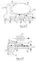
- Cooling of turbine blades in jet engines is highly important in order to maintain structural integrity and allow the engine to operate at higher temperatures and therefore efficiency than would be normally acceptable with the materials from which the blade is made. Cooling is generally required throughout the turbine blade and of particular interest with regard to the present invention are the tip shrouds from each blade. Such tip shrouds are located as indicated in the attached drawing marked "Prior Art" in the area marked by circle 100. These turbine blades are at relatively high temperature and it will be appreciated that unless the temperature is limited there will be oxidation and therefore degradation resulting in a shorter operational life for these blades.
- a second prior technique for cooling of turbine blade tip shrouds is by passing cooling air over the top of the shroud surface on which turbulators are positioned to increase heat transfer efficiency.
- the second approach has the significant advantages of reducing manufacturing costs and weight induced stress within the blade.
- the main disadvantage of the second prior technique is that cooling efficiency is markedly reduced in comparison with the first prior cooling technique due to shroud tip leakage creating highly turbulent (swirling) air flow such that cooling air is rapidly dispersed and diluted prior to reaching the tip blade extremities. In such circumstances, these extremities may overheat and oxidise reducing blade life.
- a blade cooling arrangement comprising a blade tip including a coolant gallery in use upstream of flow entrainment means, the gallery including release passages to release coolant in use close to the blade tip surface whilst the flow entrainment means entrains that released coolant to facilitate flow isolation from turbulent air created by a leading shroud edge of the blade tip.
- the gallery has a core hole from a coolant supply and a cavity from which extend the release passages.
- the release passages extend laterally with an open end adjacent the flow entrainment means.
- the spacing between the open ends of each release passage and the entrainment means is determined by desired flow rate and entrainment.
- the release passages may have a slight downward inclination towards the flow entrainment means.
- the flow entrainment means comprises upstanding fins to form channels for entrainment of the coolant flow.
- the fins are above the height of the release passages.
- the fins are perpendicular to the blade tip surface.
- each fin will have substantially the same height as other fins.
- fins may have different heights, different shapes or presentation angle relative to the release passages for specific coolant entrainment as required for a particular part of the blade tip dependent upon desired cooling efficiency and/or blade structural integrity retention.
- the fins provide additional contact surface area for enhanced heat transfer from the blade tip to the coolant flow.
- the blade tip may include trip strips and/or other heat transfer augmentation features to improve heat transfer to the coolant air flow.
- an engine incorporating turbine blades including the present blade cooling arrangement described above.
- a blade tip incorporating a cooling arrangement in accordance with the present invention.
- the blade tip includes blade shrouds 1 which extend laterally across the blade tip surface. In use, these blade shrouds interengage with a casing of an engine (see Prior Art drawing) in order to provide a labyrinth type edge seal.
- a coolant gallery 7 is provided within the structure of the blade such that a coolant supply from a base coolant system provides coolant in the form of air through a core passage 8 to the gallery 7. The gallery 7 releases coolant air over the surface of the blade tip in order to provide cooling. As can be seen, the gallery 7 is positioned downstream of the shroud 1 but upstream of flow entrainment elements 2.
- Fig. 2 illustrates that the gallery 7 releases the coolant through holes 5 adjacent the entrainment elements 2.
- entrainment elements 2 are generally upstanding fins substantially perpendicular to the blade tip surface 12 and normally extend above the height of the release passages 5 to ensure adequate entrainment of the coolant flow released through those passages 5.
- the blade tip will rotate relatively quickly with the turbine blade of which it is a part.
- the entrainment elements or fins 2 are generally angled as depicted in Figs. 1 and 2.
- leading edge or blade shrouds 1 create turbulent air flow as the blade rotates and that turbulent air flow generally disperses coolant if allowed to interact with the released coolant flow.
- Figs. 3 and 4 schematically illustrate coolant air flows within a blade tip in accordance with the present invention.
- coolant air is released through holes 5 into the entrainment channels created by the entrainment elements or fins 2.
- This released coolant flow is retained in close proximity to a blade tip surface 12 in order to provide cooling of the blade tip.
- air flow over the tip shroud 1, and leading edges of the blade tip, in the direction of broken arrows 4 is turbulent.
- this turbulent air flow (broken arrows 4) cannot readily impinge or mix with the entrained and released coolant flow through the holes 5 within the channels created between the fins 2.
- the coolant flow is not dispersed or diluted and so remains effective for a longer period of time in order to cool the blade tip. It is rotation of the blade and therefore the blade tip along with the jetting effect of a positive pressure differential which provides the desired entrainment within the channels created by the entrainment elements or fins 2.
- the entrainment created by these elements 2 acts by an impeller action to force coolant air flow within the entrainment channels created by the elements 2 and this driven flow acts to inhibit penetration by the turbulent air flows (broken arrows 4) created by the shrouds 1 and so retains coolant air flow close to the blade surface for cooling purposes rather than allow that coolant air flow to be dispersed and mingled with the warmer turbulent air flows over the shrouds 1 and edges (broken arrows 4).
- the release holes or passages 5 generally extend away from a coolant gallery in order to release coolant flow (arrow head 3) towards the entrainment element 2.
- the gallery and through the passages 5 there is generally a positive pressure driving the coolant flow out of an opening 14 of the passage 5.
- the coolant flow Once the coolant flow has exited the opening 14 that pressure differential is released and the coolant can disperse.
- there is a general jet projection towards the entrainment fins 2 as a result of the positive pressure propelling coolant flow and then rotation of the fins 2 with the turbine blade as an impeller will act to "scoop" that coolant flow in order to entrain and drive the coolant flow along the channels created between the entrainment elements or fins 2.
- That forced air flow generally creates a layer strata such that penetration by the turbulent air flow 4 is inhibited and so dispersal of the coolant flow away from the surface 12 is inhibited such that the cooling function is more efficiently performed.
- the coolant flow 3 it is possible for the coolant flow 3 to be slightly downwardly inclined towards the entrainment created by the fins or elements 2 to ensure good entrainment.
- the entrainment elements or fins 2 will be substantially perpendicular to the blade tip surface 12.
- these elements or fins 2 could be shaped for improved coolant flow entrainment.
- the elements or fins 2 could include overhang features to facilitate scoop capture and therefore entrainment of the coolant flow presented through the passages 5 and opening 14.
- the entrainment elements or fins 2 will be arranged in an angular configuration as more clearly depicted in Fig. 1 which is consistent with the rotational direction of the blade on which the blade tip is located. Such angling will improve coolant flow entrainment and therefore flow strata resistance to penetration and impingement by the turbulent air flow 4.
- the embodiment depicted with respect to the Figs. is of a rearward concave (suction side) part of a blade tip.
- the present invention could also be incorporated in any position on the shroud where temperature conditions and geometry allows. It is the creation of a positive coolant air flow entrainment within the channels created by the entrainment elements or fins 2 which ensures resistance to impingement by the turbulent air flows and so greater cooling efficiency by that coolant air flow over the blade tip surface.
- the entrainment elements or fins 2 are machined into the blade tip surface and normally that part of the blade tip surface from which the shroud 1 is formed. These elements or fins 2 can be specifically machined at any desired angled, shape or height in order to provide the best performance for cooling of the blade tip surface through air bled or leaking through the passages 5. Alternatively, entrainment elements could be separate components appropriately secured to the blade tip. Generally, a consideration of the rotational speed will be taken such that the elements or fins 2 will be substantially perpendicular to the coolant flow leakage swirl direction as the blade rotates and as indicated previously will have a height above the opening 14 of the passages 5. In order to further enhance the heat transfer within the channels between the entrainment elements 2 ripple or trip strips or other heat transfer co-efficient augmentation structures can be provided for heat exchange with the coolant flow.
- a surface cooling technique is provided to ensure adequate cooling of the blade tip.
- surface cooling has the advantage of a lower weight addition along with reduced stress levels and manufacturing costs in comparison with specific provision of a large number of coolant passages and openings in the actual blade tip structure wall thickness.
- the width 6 of the blade tip can be thinner as this thickness need not incorporate the passages and openings for coolant release whilst maintaining sufficient structural integrity to resist distortion or disintegration in use.
- the entrainment elements or fins 2 allow increased cooling efficiency with surface released coolant flow by entrainment and retaining that coolant flow adjacent to the surface 12 for cooling performance.
- the specific height, shape and angular orientation of the entrainment elements or fins 2 may be consistent throughout the blade tip surface or varied dependent upon specific cooling requirements or necessity to achieve higher localised strength or cooling in the blade tip.
Landscapes
- Engineering & Computer Science (AREA)
- Mechanical Engineering (AREA)
- General Engineering & Computer Science (AREA)
- Physics & Mathematics (AREA)
- Fluid Mechanics (AREA)
- Turbine Rotor Nozzle Sealing (AREA)
Abstract
Description
Claims (12)
- A blade cooling arrangement comprising a blade tip characterised in that said blade tip includes a coolant gallery (7) in use upstream of flow entrainment means (2), the gallery (7) including release passages (5) to release coolant in use close to the blade tip surface whilst the flow entrainment means (2) entrains that released coolant to facilitate flow isolation from turbulent air created by a shroud (1) or leading edge of the blade tip.
- An arrangement as claimed in claim 1 characterised in that the gallery (7) includes a cavity from which the release passages (5) extend.
- An arrangement as claimed in claim 1 or claim 2 characterised in that the release passages (5) extend laterally towards the flow entrainment means (2).
- An arrangement as claimed in claim 1, 2 or 3 characterised in that the release passages (5) have a slight downward inclination towards the flow entrainment means (2) and in use project the coolant flow in that slight downward inclination.
- An arrangement as claimed in any preceding claim characterised in that the flow entrainment means (2) comprises upstanding fins to form channels for entrainment of the coolant flow.
- An arrangement as claimed in claim 5 characterised in that the fins (2) extend above the height of the release passages (5).
- An arrangement as claimed in claim 5 or claim 6 characterised in that the fins (2) are substantially perpendicular to the blade tip surface.
- An arrangement as claimed in any of claims 5, 6 or 7 characterised in that each fin (2) has substantially the same height.
- An arrangement as claimed in any of claims 5 to 7 characterised in that the fins (2) have different heights and/or shapes and/or presentational angles relative to the respective release passages for specific coolant entrainment as required for a particular part of the blade tip dependent upon desired cooling efficiency and/or blade structural integrity.
- An arrangement as claimed in any of claims 5 to 9 characterised in that the fins (2) provide additional contact surface area for enhanced heat transfer to the coolant air flow.
- An arrangement as claimed in any preceding claim characterised in that the flow entrainment means (2) define channels through which the coolant flow is driven in use by rotation of the blade tip.
- An arrangement as claimed in any preceding claim characterised in that the blade tip includes ripple or trip strips and/or other heat transfer augmentation features to improve heat transfer between the coolant air flow and the blade tip.
Applications Claiming Priority (2)
| Application Number | Priority Date | Filing Date | Title |
|---|---|---|---|
| GB0228443 | 2002-12-06 | ||
| GBGB0228443.8A GB0228443D0 (en) | 2002-12-06 | 2002-12-06 | Blade cooling |
Publications (2)
| Publication Number | Publication Date |
|---|---|
| EP1426554A1 true EP1426554A1 (en) | 2004-06-09 |
| EP1426554B1 EP1426554B1 (en) | 2007-02-21 |
Family
ID=9949160
Family Applications (1)
| Application Number | Title | Priority Date | Filing Date |
|---|---|---|---|
| EP03257220A Expired - Lifetime EP1426554B1 (en) | 2002-12-06 | 2003-11-15 | Blade cooling |
Country Status (4)
| Country | Link |
|---|---|
| US (1) | US7037075B2 (en) |
| EP (1) | EP1426554B1 (en) |
| DE (1) | DE60311944T2 (en) |
| GB (1) | GB0228443D0 (en) |
Cited By (1)
| Publication number | Priority date | Publication date | Assignee | Title |
|---|---|---|---|---|
| WO2009154891A1 (en) * | 2008-06-16 | 2009-12-23 | General Electric Company | Windward cooled turbine nozzle |
Families Citing this family (4)
| Publication number | Priority date | Publication date | Assignee | Title |
|---|---|---|---|---|
| US20090110561A1 (en) * | 2007-10-29 | 2009-04-30 | Honeywell International, Inc. | Turbine engine components, turbine engine assemblies, and methods of manufacturing turbine engine components |
| US8257035B2 (en) * | 2007-12-05 | 2012-09-04 | Siemens Energy, Inc. | Turbine vane for a gas turbine engine |
| US8092178B2 (en) * | 2008-11-28 | 2012-01-10 | Pratt & Whitney Canada Corp. | Turbine blade for a gas turbine engine |
| PL2402559T3 (en) * | 2010-07-01 | 2019-04-30 | MTU Aero Engines AG | Turbine blade with tip shroud |
Citations (8)
| Publication number | Priority date | Publication date | Assignee | Title |
|---|---|---|---|---|
| US3876330A (en) * | 1972-04-20 | 1975-04-08 | Rolls Royce 1971 Ltd | Rotor blades for fluid flow machines |
| GB1426049A (en) * | 1972-10-21 | 1976-02-25 | Rolls Royce | Rotor blade for a gas turbine engine |
| GB2005775A (en) * | 1977-10-08 | 1979-04-25 | Rolls Royce | Cooled rotor blade for a gas turbine engine |
| JPS5847104A (en) * | 1981-09-11 | 1983-03-18 | Agency Of Ind Science & Technol | Turbine rotor blade in gas turbine |
| US4940388A (en) * | 1988-12-07 | 1990-07-10 | Rolls-Royce Plc | Cooling of turbine blades |
| US5531568A (en) * | 1994-07-02 | 1996-07-02 | Rolls-Royce Plc | Turbine blade |
| US20010048878A1 (en) * | 1999-04-01 | 2001-12-06 | General Electric Company | Cooling circuit for a gas turbine bucket and tip shroud |
| US20020098078A1 (en) * | 2000-12-22 | 2002-07-25 | Alexander Beeck | Device and method for cooling a platform of a turbine blade |
Family Cites Families (6)
| Publication number | Priority date | Publication date | Assignee | Title |
|---|---|---|---|---|
| US4390320A (en) * | 1980-05-01 | 1983-06-28 | General Electric Company | Tip cap for a rotor blade and method of replacement |
| US5695321A (en) * | 1991-12-17 | 1997-12-09 | General Electric Company | Turbine blade having variable configuration turbulators |
| US5503529A (en) * | 1994-12-08 | 1996-04-02 | General Electric Company | Turbine blade having angled ejection slot |
| US5733102A (en) * | 1996-12-17 | 1998-03-31 | General Electric Company | Slot cooled blade tip |
| US6672829B1 (en) * | 2002-07-16 | 2004-01-06 | General Electric Company | Turbine blade having angled squealer tip |
| US6790005B2 (en) * | 2002-12-30 | 2004-09-14 | General Electric Company | Compound tip notched blade |
-
2002
- 2002-12-06 GB GBGB0228443.8A patent/GB0228443D0/en not_active Ceased
-
2003
- 2003-11-15 DE DE60311944T patent/DE60311944T2/en not_active Expired - Lifetime
- 2003-11-15 EP EP03257220A patent/EP1426554B1/en not_active Expired - Lifetime
- 2003-12-01 US US10/724,100 patent/US7037075B2/en not_active Expired - Lifetime
Patent Citations (8)
| Publication number | Priority date | Publication date | Assignee | Title |
|---|---|---|---|---|
| US3876330A (en) * | 1972-04-20 | 1975-04-08 | Rolls Royce 1971 Ltd | Rotor blades for fluid flow machines |
| GB1426049A (en) * | 1972-10-21 | 1976-02-25 | Rolls Royce | Rotor blade for a gas turbine engine |
| GB2005775A (en) * | 1977-10-08 | 1979-04-25 | Rolls Royce | Cooled rotor blade for a gas turbine engine |
| JPS5847104A (en) * | 1981-09-11 | 1983-03-18 | Agency Of Ind Science & Technol | Turbine rotor blade in gas turbine |
| US4940388A (en) * | 1988-12-07 | 1990-07-10 | Rolls-Royce Plc | Cooling of turbine blades |
| US5531568A (en) * | 1994-07-02 | 1996-07-02 | Rolls-Royce Plc | Turbine blade |
| US20010048878A1 (en) * | 1999-04-01 | 2001-12-06 | General Electric Company | Cooling circuit for a gas turbine bucket and tip shroud |
| US20020098078A1 (en) * | 2000-12-22 | 2002-07-25 | Alexander Beeck | Device and method for cooling a platform of a turbine blade |
Non-Patent Citations (1)
| Title |
|---|
| PATENT ABSTRACTS OF JAPAN vol. 007, no. 128 (M - 220) 3 June 1983 (1983-06-03) * |
Cited By (4)
| Publication number | Priority date | Publication date | Assignee | Title |
|---|---|---|---|---|
| WO2009154891A1 (en) * | 2008-06-16 | 2009-12-23 | General Electric Company | Windward cooled turbine nozzle |
| GB2473971A (en) * | 2008-06-16 | 2011-03-30 | Gen Electric | Windward cooled turbine nozzle |
| JP2011524485A (en) * | 2008-06-16 | 2011-09-01 | ゼネラル・エレクトリック・カンパニイ | Upwind cooling turbine nozzle |
| GB2473971B (en) * | 2008-06-16 | 2012-07-11 | Gen Electric | Windward cooled turbine nozzle |
Also Published As
| Publication number | Publication date |
|---|---|
| US20040109754A1 (en) | 2004-06-10 |
| DE60311944D1 (en) | 2007-04-05 |
| GB0228443D0 (en) | 2003-01-08 |
| US7037075B2 (en) | 2006-05-02 |
| EP1426554B1 (en) | 2007-02-21 |
| DE60311944T2 (en) | 2007-06-14 |
Similar Documents
| Publication | Publication Date | Title |
|---|---|---|
| US7632062B2 (en) | Turbine rotor blades | |
| EP2131108B1 (en) | Counter-vortex film cooling hole design | |
| US6609884B2 (en) | Cooling of gas turbine engine aerofoils | |
| JP4063938B2 (en) | Turbulent structure of the cooling passage of the blade of a gas turbine engine | |
| US7503748B2 (en) | Mounting arrangement for turbine blades | |
| US5370499A (en) | Film cooling of turbine airfoil wall using mesh cooling hole arrangement | |
| CN104685160B (en) | Rotor blades for a turbine of a gas turbine engine | |
| JP3416447B2 (en) | Gas turbine blade cooling air supply system | |
| US6241468B1 (en) | Coolant passages for gas turbine components | |
| CN100350132C (en) | Turbine blade | |
| JP5038835B2 (en) | Stator-rotor assembly having surface features to enhance gas flow confinement and related processes | |
| CN101235728B (en) | Impingement cooled bucket shroud, turbine rotor incorporating the same, and cooling method | |
| JP2008298074A (en) | Stator-rotor assembly having surface features for enhancing gas flow confinement and related methods | |
| EP1302628A2 (en) | Airfoil with indentations to enhance heat transfer | |
| JP2005054776A (en) | Cooling circuit for gas-turbine blade | |
| EP2131109A2 (en) | Counter-vortex, paired film cooling hole design | |
| GB2112868A (en) | A coolable airfoil for a rotary machine | |
| JP6984100B2 (en) | Turbine vanes and gas turbines containing them | |
| JP2004225690A (en) | Turbine rotor blade and gas turbine | |
| JP2005315261A (en) | Turbulator on lower surface of turbine blade tip reversal and related method | |
| CA2872565A1 (en) | Turbine airfoil cooling passage with diamond turbulator | |
| US7037075B2 (en) | Blade cooling | |
| JP3276305B2 (en) | Gas turbine cooling vanes | |
| JP2004036510A (en) | Moving blade shroud for gas turbine | |
| JPH0463901A (en) | Gas turbine cooling blade |
Legal Events
| Date | Code | Title | Description |
|---|---|---|---|
| PUAI | Public reference made under article 153(3) epc to a published international application that has entered the european phase |
Free format text: ORIGINAL CODE: 0009012 |
|
| 17P | Request for examination filed |
Effective date: 20040408 |
|
| AK | Designated contracting states |
Kind code of ref document: A1 Designated state(s): AT BE BG CH CY CZ DE DK EE ES FI FR GB GR HU IE IT LI LU MC NL PT RO SE SI SK TR |
|
| AX | Request for extension of the european patent |
Extension state: AL LT LV MK |
|
| 17Q | First examination report despatched |
Effective date: 20050117 |
|
| AKX | Designation fees paid |
Designated state(s): DE FR GB |
|
| GRAP | Despatch of communication of intention to grant a patent |
Free format text: ORIGINAL CODE: EPIDOSNIGR1 |
|
| GRAS | Grant fee paid |
Free format text: ORIGINAL CODE: EPIDOSNIGR3 |
|
| GRAA | (expected) grant |
Free format text: ORIGINAL CODE: 0009210 |
|
| AK | Designated contracting states |
Kind code of ref document: B1 Designated state(s): DE FR GB |
|
| REG | Reference to a national code |
Ref country code: GB Ref legal event code: FG4D |
|
| REF | Corresponds to: |
Ref document number: 60311944 Country of ref document: DE Date of ref document: 20070405 Kind code of ref document: P |
|
| ET | Fr: translation filed | ||
| PLBE | No opposition filed within time limit |
Free format text: ORIGINAL CODE: 0009261 |
|
| STAA | Information on the status of an ep patent application or granted ep patent |
Free format text: STATUS: NO OPPOSITION FILED WITHIN TIME LIMIT |
|
| 26N | No opposition filed |
Effective date: 20071122 |
|
| REG | Reference to a national code |
Ref country code: FR Ref legal event code: PLFP Year of fee payment: 13 |
|
| PGFP | Annual fee paid to national office [announced via postgrant information from national office to epo] |
Ref country code: DE Payment date: 20151127 Year of fee payment: 13 Ref country code: GB Payment date: 20151127 Year of fee payment: 13 |
|
| PGFP | Annual fee paid to national office [announced via postgrant information from national office to epo] |
Ref country code: FR Payment date: 20151117 Year of fee payment: 13 |
|
| REG | Reference to a national code |
Ref country code: DE Ref legal event code: R119 Ref document number: 60311944 Country of ref document: DE |
|
| GBPC | Gb: european patent ceased through non-payment of renewal fee |
Effective date: 20161115 |
|
| REG | Reference to a national code |
Ref country code: FR Ref legal event code: ST Effective date: 20170731 |
|
| PG25 | Lapsed in a contracting state [announced via postgrant information from national office to epo] |
Ref country code: FR Free format text: LAPSE BECAUSE OF NON-PAYMENT OF DUE FEES Effective date: 20161130 |
|
| PG25 | Lapsed in a contracting state [announced via postgrant information from national office to epo] |
Ref country code: GB Free format text: LAPSE BECAUSE OF NON-PAYMENT OF DUE FEES Effective date: 20161115 Ref country code: DE Free format text: LAPSE BECAUSE OF NON-PAYMENT OF DUE FEES Effective date: 20170601 |