EP1426290B1 - Actuator for aircraft stabilizers with a failure responsive lock control mechanism - Google Patents
Actuator for aircraft stabilizers with a failure responsive lock control mechanism Download PDFInfo
- Publication number
- EP1426290B1 EP1426290B1 EP03257589A EP03257589A EP1426290B1 EP 1426290 B1 EP1426290 B1 EP 1426290B1 EP 03257589 A EP03257589 A EP 03257589A EP 03257589 A EP03257589 A EP 03257589A EP 1426290 B1 EP1426290 B1 EP 1426290B1
- Authority
- EP
- European Patent Office
- Prior art keywords
- stabilizer
- nut
- ballscrew
- engagement
- slide member
- Prior art date
- Legal status (The legal status is an assumption and is not a legal conclusion. Google has not performed a legal analysis and makes no representation as to the accuracy of the status listed.)
- Expired - Lifetime
Links
Images






Classifications
-
- F—MECHANICAL ENGINEERING; LIGHTING; HEATING; WEAPONS; BLASTING
- F16—ENGINEERING ELEMENTS AND UNITS; GENERAL MEASURES FOR PRODUCING AND MAINTAINING EFFECTIVE FUNCTIONING OF MACHINES OR INSTALLATIONS; THERMAL INSULATION IN GENERAL
- F16H—GEARING
- F16H25/00—Gearings comprising primarily only cams, cam-followers and screw-and-nut mechanisms
- F16H25/18—Gearings comprising primarily only cams, cam-followers and screw-and-nut mechanisms for conveying or interconverting oscillating or reciprocating motions
- F16H25/20—Screw mechanisms
- F16H25/22—Screw mechanisms with balls, rollers, or similar members between the co-operating parts; Elements essential to the use of such members
- F16H25/2204—Screw mechanisms with balls, rollers, or similar members between the co-operating parts; Elements essential to the use of such members with balls
-
- B—PERFORMING OPERATIONS; TRANSPORTING
- B64—AIRCRAFT; AVIATION; COSMONAUTICS
- B64C—AEROPLANES; HELICOPTERS
- B64C13/00—Control systems or transmitting systems for actuating flying-control surfaces, lift-increasing flaps, air brakes, or spoilers
- B64C13/24—Transmitting means
- B64C13/26—Transmitting means without power amplification or where power amplification is irrelevant
- B64C13/28—Transmitting means without power amplification or where power amplification is irrelevant mechanical
- B64C13/34—Transmitting means without power amplification or where power amplification is irrelevant mechanical using toothed gearing
-
- F—MECHANICAL ENGINEERING; LIGHTING; HEATING; WEAPONS; BLASTING
- F16—ENGINEERING ELEMENTS AND UNITS; GENERAL MEASURES FOR PRODUCING AND MAINTAINING EFFECTIVE FUNCTIONING OF MACHINES OR INSTALLATIONS; THERMAL INSULATION IN GENERAL
- F16H—GEARING
- F16H25/00—Gearings comprising primarily only cams, cam-followers and screw-and-nut mechanisms
- F16H25/18—Gearings comprising primarily only cams, cam-followers and screw-and-nut mechanisms for conveying or interconverting oscillating or reciprocating motions
- F16H25/20—Screw mechanisms
- F16H25/2025—Screw mechanisms with means to disengage the nut or screw from their counterpart; Means for connecting screw and nut for stopping reciprocating movement
-
- F—MECHANICAL ENGINEERING; LIGHTING; HEATING; WEAPONS; BLASTING
- F16—ENGINEERING ELEMENTS AND UNITS; GENERAL MEASURES FOR PRODUCING AND MAINTAINING EFFECTIVE FUNCTIONING OF MACHINES OR INSTALLATIONS; THERMAL INSULATION IN GENERAL
- F16H—GEARING
- F16H25/00—Gearings comprising primarily only cams, cam-followers and screw-and-nut mechanisms
- F16H25/18—Gearings comprising primarily only cams, cam-followers and screw-and-nut mechanisms for conveying or interconverting oscillating or reciprocating motions
- F16H25/20—Screw mechanisms
- F16H25/205—Screw mechanisms comprising alternate power paths, e.g. for fail safe back-up
-
- F—MECHANICAL ENGINEERING; LIGHTING; HEATING; WEAPONS; BLASTING
- F16—ENGINEERING ELEMENTS AND UNITS; GENERAL MEASURES FOR PRODUCING AND MAINTAINING EFFECTIVE FUNCTIONING OF MACHINES OR INSTALLATIONS; THERMAL INSULATION IN GENERAL
- F16H—GEARING
- F16H25/00—Gearings comprising primarily only cams, cam-followers and screw-and-nut mechanisms
- F16H25/18—Gearings comprising primarily only cams, cam-followers and screw-and-nut mechanisms for conveying or interconverting oscillating or reciprocating motions
- F16H25/20—Screw mechanisms
- F16H25/24—Elements essential to such mechanisms, e.g. screws, nuts
- F16H25/2454—Brakes; Rotational locks
-
- F—MECHANICAL ENGINEERING; LIGHTING; HEATING; WEAPONS; BLASTING
- F16—ENGINEERING ELEMENTS AND UNITS; GENERAL MEASURES FOR PRODUCING AND MAINTAINING EFFECTIVE FUNCTIONING OF MACHINES OR INSTALLATIONS; THERMAL INSULATION IN GENERAL
- F16H—GEARING
- F16H61/00—Control functions within control units of change-speed- or reversing-gearings for conveying rotary motion ; Control of exclusively fluid gearing, friction gearing, gearings with endless flexible members or other particular types of gearing
- F16H61/12—Detecting malfunction or potential malfunction, e.g. fail safe ; Circumventing or fixing failures
-
- Y—GENERAL TAGGING OF NEW TECHNOLOGICAL DEVELOPMENTS; GENERAL TAGGING OF CROSS-SECTIONAL TECHNOLOGIES SPANNING OVER SEVERAL SECTIONS OF THE IPC; TECHNICAL SUBJECTS COVERED BY FORMER USPC CROSS-REFERENCE ART COLLECTIONS [XRACs] AND DIGESTS
- Y10—TECHNICAL SUBJECTS COVERED BY FORMER USPC
- Y10T—TECHNICAL SUBJECTS COVERED BY FORMER US CLASSIFICATION
- Y10T74/00—Machine element or mechanism
- Y10T74/19—Gearing
- Y10T74/19642—Directly cooperating gears
- Y10T74/19698—Spiral
- Y10T74/19702—Screw and nut
-
- Y—GENERAL TAGGING OF NEW TECHNOLOGICAL DEVELOPMENTS; GENERAL TAGGING OF CROSS-SECTIONAL TECHNOLOGIES SPANNING OVER SEVERAL SECTIONS OF THE IPC; TECHNICAL SUBJECTS COVERED BY FORMER USPC CROSS-REFERENCE ART COLLECTIONS [XRACs] AND DIGESTS
- Y10—TECHNICAL SUBJECTS COVERED BY FORMER USPC
- Y10T—TECHNICAL SUBJECTS COVERED BY FORMER US CLASSIFICATION
- Y10T74/00—Machine element or mechanism
- Y10T74/19—Gearing
- Y10T74/19642—Directly cooperating gears
- Y10T74/19698—Spiral
- Y10T74/19702—Screw and nut
- Y10T74/19744—Rolling element engaging thread
- Y10T74/19749—Recirculating rolling elements
Definitions
- the present invention relates to horizontal stabilizer actuators for selectively controlling the operative position of aircraft stabilizers.
- Modern aircraft have horizontal stabilizers located at the tail section of the fuselage or the rudder section that are pivotally supported relative to the airplane fuselage to "trim" the aircraft during flight by selective adjustment by the operator or pilot from an internal control unit.
- the stabilizer is traditionally pivotally connected to the rudder section or tail section of the fuselage at a point generally midway along its length.
- One common trimmable horizontal stabilizer actuator consists of a primary ball nut assembly connected with an actuating drive gimbal which is pivotally connected to one end of the horizontal stabilizer structure.
- the ball nut assembly includes a ball nut housing and a rotatable ballscrew extending axially and usually vertically through the ball nut housing and a drive gimbal housing.
- the ball nut housing is connected to the drive gimbal housing by a trunnion segment.
- the ballscrew has its upper end remote from the actuating drive gimbal and is fixed from translation or axial movement by a connection to a second, support gimbal which is pivotally secured to the rudder section or the tail section. As the ballscrew is rotated, the drive gimbal will be moved in translation relative to it.
- the leading edge of the horizontal stabilizer is pivoted upward, whereas by rotating the ballscrew in the other direction, the leading edge of the horizontal stabilizer is pivoted downward.
- Rotation of the ballscrew is routinely done by a motor and associated gearing which is connected to the second, fixed support gimbal and which is actuated by the operator or pilot by the internal control unit.
- the connection of the stabilizer actuator to the stabilizer is located within the rudder or fuselage tail section and not directly in the air stream.
- the horizontal stabilizer movement is transmitted by the ballscrew through the actuating drive gimbal by way of the primary ball nut assembly which defines a primary load path.
- the movement has a load with tensile and compressive components as well as a torque component due to the ballscrew thread lead. Failures of the primary load path such as caused by the shearing off of the connecting trunnion segment or by the loss of nut ball members from the ball nut assembly can result in the complete loss of control of the horizontal stabilizer.
- stabilizer actuators have frequently been provided with a secondary load path for alternate control of the stabilizer.
- the primary load path is normally controllably actuated by the operator and is thus under load while the secondary load path is normally unactuated and thus unloaded.
- the secondary load path is automatically mobilized whereby the stabilizer actuator can continue to be controllably actuated by the operator or pilot by the internal control unit to control the position of the stabilizer. The transition of control to the secondary load path can occur quite rapidly whereby failure of the primary load path is not necessarily detected by the operator or pilot.
- the stabilizer actuator is also provided with a primary and secondary load path.
- the secondary load path will be automatically actuated to trigger the actuator to a locked condition to hold the horizontal stabilizer in a fixed position.
- An actuator of this kind is disclosed in prior art document US 2002/0104394. This avoids erratic movement of the stabilizer and hence permits the pilot to regain control through other mechanisms whereby the continued flight and landing of the aircraft can be more readily controlled.
- the locking, operation of the secondary load path shall be clearly detected by the pilot or operator during the flight by shutting down the drive system and holding the horizontal stabilizer in a fixed, position. Steps can then be taken to repair or replace the stabilizer actuator prior to the next flight.
- the apparatus for the secondary load path includes a locking mechanism which operates in response to minimal uncontrolled movement of the stabilizer and minimal triggering loads relative to the operating load in response to a failure of the primary load path. Once it is triggered to a locked condition the locking mechanism stays lockingly engaged regardless of varying aerodynamic loads on the stabilizer and hence on the stabilizer actuator and regardless of attempted control of the stabilizer actuator by the operator through the internal control unit.
- the stabilizer actuator of the present invention provides:
- Figure 1 is a schematic drawing generally depicting the assembly of the stabilizer actuator and the stabilizer relative to an aircraft rudder section or tail section of the fuselage;
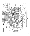
- Figure 2 is a perspective view of the stabilizer actuator including a primary ball nut assembly of a primary load path section and a secondary nut assembly of a secondary load path section with some parts removed and/or broken away for clarity;
- Figure 2A is a sectional view of the stabilizer actuator of Figure 2 taken generally in the direction of the Arrows 2A-2A in Figure 2 with some elements for connection to the stabilizer generally shown in phantom;
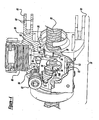
- Figure 3 is a view similar to Figure 2 depicting the secondary nut assembly of the stabilizer actuator in a set, unlocked condition with the primary load path section removed for clarity;
- Figure 4 is a view similar to Figure 3 depicting the secondary toad path section with the secondary nut assembly of the stabilizer actuator triggered to a locked condition for holding the stabilizer actuator locked;
- Figure 5 is an exploded, perspective view of a slider, split nut halves of a locking split nut and a locking piston in a disassembled condition and includes a perspective view of the locking piston shown in an inverted position for clarity,
- Figure 5A is an enlarged fragmentary, perspective view of the locking split nut in a partially assembled relationship with the slider;
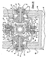
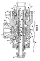
- Figure 6 is a longitudinal sectional view of the primary and secondary nut assemblies of the stabilizer actuator with the primary load path in its normally operative condition and with the secondary load path in its set, unlocked condition;
- Figure 7 is a view similar to Figure 6 depicting the secondary load path section in its initial, triggered condition upon loss of the primary load path section by a failure of the trunnion segment in a ball nut housing in the primary load path section;
- Figure 8 is a view similar to Figure 7 depicting the secondary load path section being moved to its fully locked, triggered condition immobilizing the stabilizer actuator;
- Figure 9 is a view similar to Figure 8 depicting the secondary load path section of the stabilizer actuator in its fully triggered condition upon loss of the primary load path section by a failure of the nut ball members of the ball nut in the primary load path section and being moved to its fully locked condition immobilizing the stabilizer actuator, and
- Figure 10 is a view similar to Figures 8 and 9 depicting the secondary load path section being manually actuated to its fully locked condition to immobilize the stabilizer actuator for an in-situ test and check.
- the present invention provides an improved stabilizer actuator with means for braking the stabilizer actuator to immobilize it and shut down the horizontal stabilizer drive system in the event of primary load path failure. Once this is done no further external loads are required to maintain the locked condition. In this regard, once there is a failure in the primary load path, only a relatively small percentage of the aerodynamic load on the stabilizer is required to activate or trigger the secondary load path to its locked condition. At the same time, after triggering the initiation of the locking actuation the uncontrolled movement of the stabilizer is substantially instantly stopped.
- the actuator 10 includes a primary load path section generally indicated by the numeral 14 having a primary ball nut assembly 16.
- the primary ball nut assembly 16 includes a ball nut housing 18 connected by threads with a ballscrew 20 via a plurality of nut ball members 22. Only a few nut ball members 22 are shown in the drawings.
- the ballscrew 20 extends generally vertically and is connected at its upper end to a hydraulic or electric drive motor and gear assembly 24.
- An end cap 25 is fixed to the opposite lower end of the ball screw 20 to assure that the ballscrew 20 will not be unthreaded from the primary ball nut assembly 16.
- the drive motor and gear assembly 24 is connected to an upper support gimbal 26 which in turn is pivotally secured at a fixed position to a portion of the rudder section or tail section 28 of the fuselage.
- the drive motor and gear assembly 24 and the details thereof are of a construction well known in the art and thus it is only generally shown for purposes of simplicity and brevity.
- the pilot through operation of an internal control unit 35 will energize the drive motor and gear assembly 24 to rotate the ballscrew 20 in one direction which will move the primary ball nut assembly 16 and drive gimbal 34 upward along the axially fixed ballscrew 20 to pivot the forward end 32 of the stabilizer 12 upward or to rotate the ballscrew 20 in the opposite direction which will move the primary ball nut assembly 16 and drive gimbal 34 downward along the fixed ballscrew 20 to pivot the forward end 32 downward.
- the stabilizer actuator 10 is pivoted at the fixed support gimbal 26 and pivoted at the movable drive gimbal 34 to accommodate the angular, arcuate displacement of the forward end 32 of the stabilizer 12.
- apparatus such as an internal control unit 35 are well known in the art and thus details thereof have been omitted for purposes of brevity and simplicity.
- the primary load path section 14 includes the primary ball nut assembly 16 which has the ball nut housing 18 with helically extending, arcuately shaped grooves 30 on its inner surface. A plurality of nut ball members 22 are matingly located in the housing grooves 30.
- the ballscrew 20 extends through the nut housing 18 and in turn has helically extending, arcuately shaped grooves or threads 37 on its outer surface which are also adapted to matingly receive the nut ball members 22.
- such basic structures, which are used to transfer loads by relative rotation with reduced friction, are well known in the art and hence the specific details thereof have been omitted for purposes of simplicity and brevity.
- the primary load path section 14 includes a primary or drive gimbal housing 42 which has a pair of oppositely extending support rod assemblies 44 each of which includes an outer sleeve 53 and connecting bolt 46. See Figure 2A.
- the stabilizer 12 is pivotally connected to the support rod assemblies 44 via a generally U-shaped connecting arm 40.
- the connecting bolt 46 secures the connecting arm. 40 to the support rod assemblies 44 and thereby to the primary gimbal housing 42.
- the nut housing 18 in turn is connected to the primary gimbal housing 42 via a pair of diametrically spaced trunnion segments 48.
- Each trunnion segment 48 includes a spherical ball member 50 which is pivotally secured within a partially spherical cavity in a retainer 52 in the primary, drive gimbal housing 42. This pivotal type connection provides a limited amount of movement of the ballscrew 20 and nut housing 18 relative to the primary gimbal housing 42 to accommodate various loads and positions of the stabilizer 12.
- the spherical ball members 50 are axially held in place by T shaped bolts 50a which are threadably connected to threaded bores in the trunnion segments 48.
- the secondary load path section 36 includes a secondary housing assembly which includes a secondary nut housing 56 which is connected to a secondary gimbal ring housing 57. It can be seen that the apparatus for the primary load path section 14 is located generally within the secondary gimbal ring housing 57.
- the secondary gimbal ring housing 57 includes a main secondary housing section 67 and secondary gimbal pivot connectors 69 which are secured together by threaded fasteners 71.
- the secondary gimbal ring housing 57 is pivotally connected to the connecting arm 40 from the stabilizer 12 via a pair of diametrically oppositely located annular gimbal rings 55 extending from ring flanges 79 on each of the pivot connectors 69.
- the fasteners 71 secure the pivot connectors 69 to the inside of the main secondary housing section 67 through the ring flanges 79. It can be readily seen that this connection then will maintain the secondary load path section 36 pivotally connected to the stabilizer 12 via the connecting arm 40 even in the event of failure of the primary load path section 14, to be described. It can be seen then that this structure in the secondary load path section 36 defines a connecting gimbal structure separate from the drive gimbal 34.
- the U-shaped connecting arm 40 includes two pairs of spaced inner and outer plates 40a and 40b, respectively.
- the generally U-shaped configuration of the connecting arm 40 is defined by the connection of both pairs of plates 40a and 40b as generally shown at connection 39.
- the inner plates 40a are provided with large diameter through bores 41 while the outer plates 40b are provided with smaller diameter through bores 43.
- Spherical bearings 47 are located in the bores 43 in the outer plates 40b.
- the annular rings 55 of the pivot connectors 69 are rotatably supported in the large diameter bores 41 while the support rod assemblies 44 are rotatably supported in the spherical bearings 47 by engagement with the sleeves 53.
- the fasteners 71 are removed such that the pivot connectors 69 can be located inwardly with the rings 55 in clearance with the inner surfaces of the inner plates 40b of U-shaped connecting arm 40.
- the support rod assembles 44 are not yet assembled to the drive gimbal housing 42.
- the main secondary housing section 67 can be moved into the opening of the U-shaped connecting arm 40 and the gimbal pivot connectors 69 can be secured by the fasteners 71 with the gimbal rings 55 located in the bores 41.
- the support rod assemblies 44 can be extended through bearings 47 in the outer plates 40b with the connecting bolt 46 threaded into a bore 49 in the primary gimbal housing 42.
- the sleeve 53 is supported in the bearing 47 and extends into a counterbore 51 adjacent the threaded bore 49.
- flanges 45 at the outer end of the sleeves 53 are adapted to overengage the outer ends of the spherical bearings 47 to assist in maintaining them in the bores 43.
- This then connects the secondary load path via the secondary housing section 67 and the primary load path via the primary gimbal housing 42 to the stabilizer 12.
- the secondary nut housing 56 is connected to the secondary gimbal ring housing 57 by a pair of diametrically opposite pivot pin assemblies 59.
- the pivot pin assemblies 59 include a cylindrical pivot pin 73 which is held in place by a plate 75 which is secured to the secondary nut housing by a pair of bolts 77 (only one shown in Figure 2 - see Figure 2A).
- the secondary nut housing 56 has a pair of diametrically spaced U-shaped clevis structures 61 each of which has a pair of spaced through bores 63.
- the inner end of the main secondary housing section 67 of the secondary gimbal ring housing 57 is located within the clevis structures 61 and has spaced bores 65 each of which is located between and in line with a pair of through bores 63.
- the pivot pins 73 extend through the aligned bores 63 and 65 with a tight fit in bores 63 to thereby hold the gimbal ring housing 57 and the secondary nut housing 56 together.
- this connection permits a limited amount of relative pivotal and diametrical movement between the housings 56 and 57 to facilitate alignment of the interconnected elements of the primary load path section 14 and the secondary load path section 36.
- the secondary load path section 36 includes a secondary nut assembly 38 which is operably supported in the secondary nut housing 56.
- the secondary nut assembly 38 includes a locking split nut 54 located in the secondary nut housing 56.
- the split nut 54 has generally semi-circular, upper and lower nut halves 54a and 54b, respectively, which are normally biased apart by two pairs of compression springs 58.
- the split nut halves 54a and 54b were made of a lightweight, high strength titanium alloy such as Ti-6Al-4V.
- the ballscrew 20 is made of an even higher strength steel alloy such as an induction hardenable stainless steel.
- the split nut 54 can be actuated to be forced against the ballscrew 20 by application of a radial force generated by a spring 60 acting on a lock actuating piston 62 supported in the secondary nut housing 56. Locking of the stabilizer 12 is achieved by the clamping of the split nut 54 against the ballscrew 20.
- the split nut 54 is provided with helically extending, arcuately and helically shaped segments of threads 68a and 68b on the split nut halves 54a and 54b, respectively, adapted to matingly engage the ballscrew threads 37 with some interference. See Figures 5 and 5a.
- the split nut threads 68a and 68b are of a form which is selected such that the frictional engagement between the inverted nut threads 68a and 68b of the split nut 54 and the ballscrew threads 37 provides the necessary braking required to stall the horizontal stabilizer actuator 10.
- the arcuate form of the threads 68a and 68b on the split nut halves 54a and 54b are contoured such as to provide initial limited surface engagement with the ballscrew threads 37 at an angle of around 45°. As the engagement force on the split nut halves 54a and 54b increases, the split nut threads 68a and 68b will resiliently deform slightly to increase the engagement area with the ballscrew threads 37.
- this limited engagement area provides a high magnitude of frictional engagement to enhance the braking action to resist and inhibit rotation of the ballscrew 20 when actuated to the locked condition.
- the number of threads 68a and 68b is selected to provide a sufficient number to optimize the engaged surface area to provide the needed strength and frictional resistance. For example around seven such threads 68a and 68b are shown in the drawings.
- the piston 62 which is load biased by the spring 60 is normally held away from the split nut 54 by a split nut retainer, slider 66.
- the slider 66 is generally cylindrical with a slotted, radially U-shaped open section 70 at one end which has a pair of parallel, spaced walls 74.
- the piston 62 has a transversely extending piston roller 64 with portions extending from each side of the piston 62 which are adapted to engage the upper surfaces of the walls 74.
- the piston roller 64 is rotatably supported on a needle bearing structure 80 located within the piston 62.
- Each of the upper surfaces of slider 66 has a substantially straight axially extending hold-off section 76 at one axial end and a downwardly inclined ramp section 78 at its opposite end.
- the end of the slider 66 opposite from the slotted, open section 70 is closed and has an upper, generally flat axially extending surface provided with gear teeth defining a gear rack 86 which serves a purpose to be described.
- the bottom end of the piston 62 is normally located partially in the slotted, open section 70 in a fixed position spaced from the upper nut half 54a. Upon actuation in response to failure of the primary load path the bottom end of the piston 62 will be moved further into the slotted, open section 70 into compressive engagement with the upper nut half 54a as shown in Figures 4 and 8.
- the upper surface 88 of the upper nut half 54a is arcuately formed with a plurality of arcuate transverse grooves 89 while the lower surface 90 of the piston 62, which is adapted to engage the upper surface 88, is similarly arcuately formed with mating arcuate transverse grooves 97.
- the formation of the grooves 89 and 97 to be arcuate assures full engagement even in the event there is some, even slight, circumferential rotation between the two. Whereas planar grooves would not necessarily compensate for such rotation and have full engagement.
- the nut retainer, slider 66 is normally held in the "SET" position by a coil spring 72 acting inside the slider 66 to resiliently bias it to a set position with an inner wall 82 against one side of piston 62. See Figure 6. With the slider 66 in this position, the force of piston 62 is applied only to the slider 66 by the engagement of the piston roller 64 on the straight sections 76 which holds the piston 62 out of engagement with the split nut 54.
- the slider 66 is movably supported on rollers 93 located within the secondary nut housing 56 and in engagement with flat shoulders 95 on the side of the slider 66 opposite from the slotted open section 70. At the same time the slider 66 has an axially extending guide channel 105 extending, centrally between the flat shoulders 95.
- a pair of locator pins 107 are connected to the secondary nut housing 56 and extend partially into the guide channel 105 to assist in maintaining the slider 66 aligned within the secondary nut housing 56. See Figures 6-10.
- the split nut halves 54a, 54b Prior to energization, the split nut halves 54a, 54b are held apart from the ballscrew threads 37 by the compression springs 58 to eliminate or reduce frictional drag loads during normal operation.
- the crests or peaks of the threads 68a and 68b on the split nut halves 54a, 54b will be located partially within the grooves of the ballscrew threads 37 but with general, axial and radial clearance between the overlapping portions of the confronting crests.
- the split nut 54 is supported within the cavity of the slider 66 generally in line with the slotted, open section 70.
- the lower, outer surface 96b of the lower split nut half 54b is rounded and is engaged with a similarly rounded lower surface 98 in the cavity of the slider 66 for relative sliding motion.
- the upper split nut half 54a is provided with a pair of flat shoulders 100.
- a pair of rectangularly shaped separate keys 102 are oppositely supported in cavities or milled slots 103 in the spaced walls 74 in the open section 70 and extend into the cavity of the slider 66 for sliding engagement with the flat shoulders 100 to maintain the upper nut half 54a at a preselected position for clearance between the transversely grooved surface 88 with the matching transversely grooved lower surface 90 of the locking piston 62.
- the compression springs 58 radially bias the split nut halves 54a and 54b away from each with the rounded lower surfaces 96b and 98 into engagement and with the flat shoulders 100 in engagement with the keys 102.
- Locking of the secondary nut assembly 38 is triggered by axial motion of the secondary nut housing 56 relative to the ballscrew 20 which is held fixed by the upper support gimbal 26. This is caused by the uncontrolled, translational movement of the stabilizer 12 upwardly in the direction of the Arrow A in Figure 1. Also see Figures 4 and 7. This motion is caused by failure in the primary load path section 14 such as by the shearing off of the trunnion segments 48 of the nut housing 18 or by the loss of nut ball members 22 from the primary ball nut assembly 16. It also will be caused by a failure at the connection of the support rod assemblies 44 between the primary gimbal housing 42 and the outer plates 40b of the connecting arm 40.
- the piston roller 64 will then roll from the straight sections 76 onto the inclined ramp sections 78 on the slider 66, forcing the slider 66 away from the piston 62 against the bias of spring 72 whereby the radial force of the piston 62 created by the spring 60 will then act directly on the split nut 54. This will then bring the arcuate, transverse grooves 97 of the surface 90 of the piston 62 into mating engagement with the arcuate, transverse grooves 89 of the surface 88 on the upper nut half 54a.
- the engagement of the piston roller 64 with the inclined ramp sections 78 creates a cam like force sufficient to fully overcome the bias of the coil spring 72 acting on the slider 66.
- the actuator 10 will remain locked even under load reversal on the stabilizer 12 in the direction of the Arrow B of Figure 1.
- the actuated split nut 54 as energized by the spring 60 against the piston 62 provides constant braking to stall and immobilize the stabilizer actuator 10 in the case of failure of the primary load path section 14.
- the bias on the piston 62 and the angle of inclination of the inclined ramp sections 78 are selected to facilitate rapid locking actuation once the piston roller 64 is moved from the straight sections 76 onto the inclined ramp sections 78.
- FIG. 6 the actuating drive gimbal 34 is shown with the primary load pivot section 14 in its normally operative condition and with the secondary load path section 36 in its set, unlocked condition. This is the condition of drive gimbal 34 as shown in Figure 1 with the secondary gimbal ring housing 57 removed. It can be seen then that the threads 68a and 68b of split nut halves 54a and 54b are held out of direct engagement with the threads 37 of the ballscrew 20. Here the piston roller 64 is held in engagement with the straight sections 76 of the upper surface of walls 74 on the slider 66 with the force of spring 60 on the piston 62.
- Figure 9 depicts the condition of the secondary nut assembly 38 with the secondary load path section 36 and thus drive gimbal 34 in the locked condition, similar to that of Figure 8, upon failure of the primary load path section 14 caused by failure in the structure of the nut ball members 22.
- ballscrew threads 37 are no longer in line with the housing grooves 30 in the ball nut housing 18.
- Any load imposed in the upward direction of Arrow A on the primary gimbal housing 42 will be transferred by the secondary annular gimbal rings 55 to the secondary gimbal ring housing 57 and hence into the secondary nut housing 56.
- This again will result in relative axial movement between the primary gimbal housing 42 and secondary nut housing 56 relative to the fixed ballscrew 20.
- Such relative movement will trigger the actuation of the secondary load path section 36 to the locked condition with the split nut half threads 68a and 68b of the split nut halves 54a and 54b. in full locking engagement with the ballscrew threads 37.
- the in-situ inspection of the spring energized split nut 54 is provided by a rack and pinion gear assembly 92, which can be externally, manually actuated with a simple drive wrench without the need for any disassembly.
- the rack and pinion gear assembly 92 includes a pinion gear 94 which is adapted to engage the rack 86 located on the upper surface of the slider 66.
- the pinion gear 94 is manually rotated, using a hand-held wrench, from the "SET" position (which can be marked on the housing) through a small angle of 20 degrees or less to the "TRIGGERED" position (which can also be marked on the housing) and this causes the slider 66 to translate axially away from the piston 62.
- the translation of the slider 66 then allows the piston 62 to move radially inwardly with the grooved lower surface 90 engaging the grooved upper surface 88 on the upper nut half 54a of the split nut 54 and move the upper and lower nut halves 54a and 54b into locking engagement with the ballscrew 20.
- the operator or tester can then attempt to actuate the stabilizer actuator 10 by the internal stabilizer control system to verify that it is permanently immobilized by the split nut 54.
- the secondary nut assembly 38 is reset by rotating the pinion gear 94 back to the "SET" position.
- the secondary load path section 36 will respond to provide the locking action in the event of failure in the primary toad path section 14 by failure of the primary ball nut assembly 16, failure of the trunnion structure 48 connection of the nut housing 18 to the primary drive gimbal housing 42 and the failure of the connection of the primary drive gimbal housing 42 to the stabilizer 12 via the connecting arms 40 with the support rod assemblies 44.
- This is provided by the use of separate housings and connections in the secondary load path section 36 and primary load path section 14 which, as noted, also facilitates alignment of the various interconnected components.
Landscapes
- Engineering & Computer Science (AREA)
- General Engineering & Computer Science (AREA)
- Mechanical Engineering (AREA)
- Automation & Control Theory (AREA)
- Aviation & Aerospace Engineering (AREA)
- Transmission Devices (AREA)
Description
- The present invention relates to horizontal stabilizer actuators for selectively controlling the operative position of aircraft stabilizers.
- Modern aircraft have horizontal stabilizers located at the tail section of the fuselage or the rudder section that are pivotally supported relative to the airplane fuselage to "trim" the aircraft during flight by selective adjustment by the operator or pilot from an internal control unit. This involves adjusting the position of the horizontal stabilizer by a stabilizer actuator to accommodate different load distributions within the aircraft and different atmospheric conditions, i.e. wind, rain, show, etc. In this regard the stabilizer is traditionally pivotally connected to the rudder section or tail section of the fuselage at a point generally midway along its length. One common trimmable horizontal stabilizer actuator consists of a primary ball nut assembly connected with an actuating drive gimbal which is pivotally connected to one end of the horizontal stabilizer structure. The ball nut assembly includes a ball nut housing and a rotatable ballscrew extending axially and usually vertically through the ball nut housing and a drive gimbal housing. The ball nut housing is connected to the drive gimbal housing by a trunnion segment. The ballscrew, in turn, has its upper end remote from the actuating drive gimbal and is fixed from translation or axial movement by a connection to a second, support gimbal which is pivotally secured to the rudder section or the tail section. As the ballscrew is rotated, the drive gimbal will be moved in translation relative to it. Thus as the ballscrew is rotated in one direction, the leading edge of the horizontal stabilizer is pivoted upward, whereas by rotating the ballscrew in the other direction, the leading edge of the horizontal stabilizer is pivoted downward. Rotation of the ballscrew is routinely done by a motor and associated gearing which is connected to the second, fixed support gimbal and which is actuated by the operator or pilot by the internal control unit. The connection of the stabilizer actuator to the stabilizer is located within the rudder or fuselage tail section and not directly in the air stream.
- The horizontal stabilizer movement, as controlled by the operator, is transmitted by the ballscrew through the actuating drive gimbal by way of the primary ball nut assembly which defines a primary load path. The movement has a load with tensile and compressive components as well as a torque component due to the ballscrew thread lead. Failures of the primary load path such as caused by the shearing off of the connecting trunnion segment or by the loss of nut ball members from the ball nut assembly can result in the complete loss of control of the horizontal stabilizer. However, stabilizer actuators have frequently been provided with a secondary load path for alternate control of the stabilizer. In such structures, the primary load path is normally controllably actuated by the operator and is thus under load while the secondary load path is normally unactuated and thus unloaded. In the event of a primary load path failure, the secondary load path is automatically mobilized whereby the stabilizer actuator can continue to be controllably actuated by the operator or pilot by the internal control unit to control the position of the stabilizer. The transition of control to the secondary load path can occur quite rapidly whereby failure of the primary load path is not necessarily detected by the operator or pilot.
- However, in the event of a subsequent failure of the secondary load path through continued, periodic use, control of the stabilizer will be completely lost which could result in erratic, oscillatory movement of the stabilizer whereby the ability of the pilot or operator to control the aircraft could be substantially inhibited. This problem is addressed by the present invention.
- The prior art is illustrated by document EP 0,983,937.
- The present invention is defined in the claims.
- In the present invention the stabilizer actuator is also provided with a primary and secondary load path. However, in the event of failure of the primary load path, the secondary load path will be automatically actuated to trigger the actuator to a locked condition to hold the horizontal stabilizer in a fixed position. An actuator of this kind is disclosed in prior art document US 2002/0104394. This avoids erratic movement of the stabilizer and hence permits the pilot to regain control through other mechanisms whereby the continued flight and landing of the aircraft can be more readily controlled. Thus the locking, operation of the secondary load path shall be clearly detected by the pilot or operator during the flight by shutting down the drive system and holding the horizontal stabilizer in a fixed, position. Steps can then be taken to repair or replace the stabilizer actuator prior to the next flight. Also, with the present invention it shall be possible to test the condition of the mechanism for the secondary load path to provide permanent immobilization by a readily accessible in-situ inspection structure of the mechanism during routine maintenance checks at periodic intervals. This is to ensure that the secondary load path mechanism is functional. As will be seen, the apparatus for the secondary load path includes a locking mechanism which operates in response to minimal uncontrolled movement of the stabilizer and minimal triggering loads relative to the operating load in response to a failure of the primary load path. Once it is triggered to a locked condition the locking mechanism stays lockingly engaged regardless of varying aerodynamic loads on the stabilizer and hence on the stabilizer actuator and regardless of attempted control of the stabilizer actuator by the operator through the internal control unit. Thus the stabilizer actuator of the present invention provides:
- 1) permanent immobilization of the stabilizer actuator via a secondary load path to hold the stabilizer in a fixed position in the event of failure of the mechanism for the primary load path;
- 2) the ability of the locking mechanism for the secondary load path to achieve permanent, fixed immobilization under minimal aerodynamic triggering loads;
- 3) the ability of the locking mechanism to keep the stabilizer actuator immobilized even though aerodynamic loads of varying magnitudes are applied to the stabilizer up to the tensile and compressive design load limits;
- 4) a clear signal to the operator, via the locked condition, by rendering the internal control unit ineffective, that there has been a failure in the primary load path and that repair should be done upon landing; and
- 5) readily accessible in-situ inspection of the locking mechanism for the secondary load path locking function during scheduled intervals to confirm that the locking mechanism should be able to operate when activated after a primary load path failure.
- Therefore it is an object of the present invention to provide an aircraft stabilizer actuator which responds in the event of failure of the primary load path to trigger a secondary load path to lock the stabilizer actuator and stabilizer in a fixed position thus inhibiting erratic, uncontrolled movement of the stabilizer.
- It is another object of the present invention to provide an aircraft stabilizer actuator which has a primary load path by which the stabilizer is normally selectively actuated by the operator and a secondary load path which will lock the stabilizer actuator to hold the stabilizer in a fixed position in the event of failure of the structure for the primary load path and further providing a means for ready, routine in-situ ground inspection of the secondary load path locking mechanism to periodically determine its operative or inoperative condition.
- Further areas of applicability of the present invention will become apparent from the detailed description provided hereinafter. It should be understood that the detailed description and specific examples, while indicating the preferred embodiment of the invention, are intended for purposes of illustration only and are not intended to limit the scope of the invention.
- The present invention will become more fully understood from the detailed description and the accompanying drawings, wherein:
- Figure 1 is a schematic drawing generally depicting the assembly of the stabilizer actuator and the stabilizer relative to an aircraft rudder section or tail section of the fuselage;
- Figure 2 is a perspective view of the stabilizer actuator including a primary ball nut assembly of a primary load path section and a secondary nut assembly of a secondary load path section with some parts removed and/or broken away for clarity;
- Figure 2A is a sectional view of the stabilizer actuator of Figure 2 taken generally in the direction of the
Arrows 2A-2A in Figure 2 with some elements for connection to the stabilizer generally shown in phantom; - Figure 3 is a view similar to Figure 2 depicting the secondary nut assembly of the stabilizer actuator in a set, unlocked condition with the primary load path section removed for clarity;
- Figure 4 is a view similar to Figure 3 depicting the secondary toad path section with the secondary nut assembly of the stabilizer actuator triggered to a locked condition for holding the stabilizer actuator locked;
- Figure 5 is an exploded, perspective view of a slider, split nut halves of a locking split nut and a locking piston in a disassembled condition and includes a perspective view of the locking piston shown in an inverted position for clarity,
- Figure 5A is an enlarged fragmentary, perspective view of the locking split nut in a partially assembled relationship with the slider;
- Figure 6 is a longitudinal sectional view of the primary and secondary nut assemblies of the stabilizer actuator with the primary load path in its normally operative condition and with the secondary load path in its set, unlocked condition;
- Figure 7 is a view similar to Figure 6 depicting the secondary load path section in its initial, triggered condition upon loss of the primary load path section by a failure of the trunnion segment in a ball nut housing in the primary load path section;
- Figure 8 is a view similar to Figure 7 depicting the secondary load path section being moved to its fully locked, triggered condition immobilizing the stabilizer actuator;
- Figure 9 is a view similar to Figure 8 depicting the secondary load path section of the stabilizer actuator in its fully triggered condition upon loss of the primary load path section by a failure of the nut ball members of the ball nut in the primary load path section and being moved to its fully locked condition immobilizing the stabilizer actuator, and
- Figure 10 is a view similar to Figures 8 and 9 depicting the secondary load path section being manually actuated to its fully locked condition to immobilize the stabilizer actuator for an in-situ test and check.
- The following description of the preferred embodiment(s) is merely exemplary in nature and is In no way intended to limit the invention, its application, or uses.
- As noted previous designs of stabilizer actuators had a secondary load path section operable by the pilot or operator for controlling the stabilizer in the event of a failure in the primary load path section. These structures relied on an inverted nut with threads in sliding engagement along the rotating ballscrew to provide a secondary load path in the case of failure in the primary load path section such as the shearing off of a connecting trunnion segment of a ball nut housing or the loss of nut ball members from the ball nut assembly. The inverted nut thread sliding against the rotating ballscrew thread does not necessarily generate enough frictional torque to stall and immobilize the horizontal actuator drive system and thus permits continued operation of the stabilizer actuator by the operator from the internal control unit. In addition since the stabilizer actuator was still responsive to the operator, the failure of the primary load path section was not necessarily detected until the next general inspection interval. Also, such previous designs did not provide a structure to allow ready in-situ inspection of the operative condition of the secondary load path section. It should be noted that aircraft also have actuators for air foils, flaps and the like which include control apparatus for providing a braking or locking action in response to overload, component failure and the like. However, such actuators and control apparatus are unlike that of the present invention.
- The present invention provides an improved stabilizer actuator with means for braking the stabilizer actuator to immobilize it and shut down the horizontal stabilizer drive system in the event of primary load path failure. Once this is done no further external loads are required to maintain the locked condition. In this regard, once there is a failure in the primary load path, only a relatively small percentage of the aerodynamic load on the stabilizer is required to activate or trigger the secondary load path to its locked condition. At the same time, after triggering the initiation of the locking actuation the uncontrolled movement of the stabilizer is substantially instantly stopped.
- Looking now to Figures 1 and 2 a
stabilizer actuator 10 is shown for selectively controlling the position of ahorizontal stabilizer 12. Theactuator 10 includes a primary load path section generally indicated by the numeral 14 having a primaryball nut assembly 16. The primaryball nut assembly 16 includes aball nut housing 18 connected by threads with aballscrew 20 via a plurality ofnut ball members 22. Only a fewnut ball members 22 are shown in the drawings. Theballscrew 20 extends generally vertically and is connected at its upper end to a hydraulic or electric drive motor andgear assembly 24. Anend cap 25 is fixed to the opposite lower end of theball screw 20 to assure that the ballscrew 20 will not be unthreaded from the primaryball nut assembly 16. The drive motor andgear assembly 24 is connected to anupper support gimbal 26 which in turn is pivotally secured at a fixed position to a portion of the rudder section ortail section 28 of the fuselage. The drive motor andgear assembly 24 and the details thereof are of a construction well known in the art and thus it is only generally shown for purposes of simplicity and brevity. - The
horizontal stabilizer 12 is pivotally connected along its length by apivot structure 29 which is fixed to the rudder section orfuselage tail section 28. Theforward end 32 of thehorizontal stabilizer 12 is in turn pivotally connected to anactuating drive gimbal 34 located generally midway along theballscrew 20 and which in turn is pivotally connected to the primaryball nut assembly 16 which is secured to thedrive gimbal 34. As noted, the connection of stabilizer actuators to the rudder section or fuselage tail section is common and well known and thus details of the rudder ortail section 28 have been omitted for purposes of brevity and simplicity. - In order to selectively set the position of the
horizontal stabilizer 12, the pilot through operation of aninternal control unit 35 will energize the drive motor andgear assembly 24 to rotate the ballscrew 20 in one direction which will move the primaryball nut assembly 16 and drivegimbal 34 upward along the axially fixedballscrew 20 to pivot theforward end 32 of thestabilizer 12 upward or to rotate the ballscrew 20 in the opposite direction which will move the primaryball nut assembly 16 and drivegimbal 34 downward along the fixedballscrew 20 to pivot theforward end 32 downward. As this occurs thestabilizer actuator 10 is pivoted at the fixedsupport gimbal 26 and pivoted at themovable drive gimbal 34 to accommodate the angular, arcuate displacement of theforward end 32 of thestabilizer 12. As noted apparatus such as aninternal control unit 35 are well known in the art and thus details thereof have been omitted for purposes of brevity and simplicity. - Also such basic operative connections as noted above, are well known in existing stabilizer actuator structures. As will be seen, in the present invention, upon failure of the primary load path section 14 a secondary
load path section 36 will be actuated to lock thestabilizer 12 in a fixed position. The secondary load path section is generally indicated by the numeral 36 in Figures 2-4. - Looking now to Figure 2, the primary load path section 14 includes the primary
ball nut assembly 16 which has theball nut housing 18 with helically extending, arcuately shapedgrooves 30 on its inner surface. A plurality ofnut ball members 22 are matingly located in thehousing grooves 30. Theballscrew 20 extends through thenut housing 18 and in turn has helically extending, arcuately shaped grooves orthreads 37 on its outer surface which are also adapted to matingly receive thenut ball members 22. As noted such basic structures, which are used to transfer loads by relative rotation with reduced friction, are well known in the art and hence the specific details thereof have been omitted for purposes of simplicity and brevity. - The primary load path section 14, includes a primary or drive
gimbal housing 42 which has a pair of oppositely extending support rod assemblies 44 each of which includes anouter sleeve 53 and connectingbolt 46. See Figure 2A. Thestabilizer 12 is pivotally connected to the support rod assemblies 44 via a generally U-shaped connectingarm 40. The connectingbolt 46 secures the connecting arm. 40 to the support rod assemblies 44 and thereby to theprimary gimbal housing 42. As can be seen in Figure 2A the diametrically opposite sides of theactuating drive gimbal 34 are substantially the same. Thenut housing 18 in turn is connected to theprimary gimbal housing 42 via a pair of diametrically spacedtrunnion segments 48. While only onesuch trunnion segment 48 is shown in Figure 2 both are shown in Figure 2A. Eachtrunnion segment 48 includes aspherical ball member 50 which is pivotally secured within a partially spherical cavity in aretainer 52 in the primary, drivegimbal housing 42. This pivotal type connection provides a limited amount of movement of theballscrew 20 andnut housing 18 relative to theprimary gimbal housing 42 to accommodate various loads and positions of thestabilizer 12. Thespherical ball members 50 are axially held in place by T shapedbolts 50a which are threadably connected to threaded bores in thetrunnion segments 48. - Thus, as noted, as the
ballscrew 20 is rotated, the primaryball nut assembly 16, which is fixed from rotation, along with the primary,gimbal housing 42 will be moved axially in translation along the ballscrew 20 to thereby pivot thehorizontal stabilizer 12 about itspivot structure 29. This structure of the primary load section 14 then provides the primary load path for actuation of thestabilizer 12 as controlled by the operator. - A secondary load path is provided by the secondary
load path section 36. The secondaryload path section 36 includes a secondary housing assembly which includes asecondary nut housing 56 which is connected to a secondarygimbal ring housing 57. It can be seen that the apparatus for the primary load path section 14 is located generally within the secondarygimbal ring housing 57. The secondarygimbal ring housing 57 includes a mainsecondary housing section 67 and secondarygimbal pivot connectors 69 which are secured together by threadedfasteners 71. - The secondary
gimbal ring housing 57 is pivotally connected to the connectingarm 40 from thestabilizer 12 via a pair of diametrically oppositely located annular gimbal rings 55 extending fromring flanges 79 on each of thepivot connectors 69. Thefasteners 71 secure thepivot connectors 69 to the inside of the mainsecondary housing section 67 through thering flanges 79. It can be readily seen that this connection then will maintain the secondaryload path section 36 pivotally connected to thestabilizer 12 via the connectingarm 40 even in the event of failure of the primary load path section 14, to be described. It can be seen then that this structure in the secondaryload path section 36 defines a connecting gimbal structure separate from thedrive gimbal 34. - Looking now to Figure 2A, the
U-shaped connecting arm 40 includes two pairs of spaced inner andouter plates arm 40 is defined by the connection of both pairs ofplates inner plates 40a are provided with large diameter throughbores 41 while theouter plates 40b are provided with smaller diameter through bores 43.Spherical bearings 47 are located in thebores 43 in theouter plates 40b. The annular rings 55 of thepivot connectors 69 are rotatably supported in the large diameter bores 41 while the support rod assemblies 44 are rotatably supported in thespherical bearings 47 by engagement with thesleeves 53. To assemble thegimbal pivot connectors 69 and hence the mainsecondary housing section 67 to theU-shaped connecting arm 40, thefasteners 71 are removed such that thepivot connectors 69 can be located inwardly with therings 55 in clearance with the inner surfaces of theinner plates 40b ofU-shaped connecting arm 40. At the same time the support rod assembles 44 are not yet assembled to thedrive gimbal housing 42. Now the mainsecondary housing section 67 can be moved into the opening of the U-shaped connectingarm 40 and thegimbal pivot connectors 69 can be secured by thefasteners 71 with the gimbal rings 55 located in thebores 41. Next the support rod assemblies 44 can be extended throughbearings 47 in theouter plates 40b with the connectingbolt 46 threaded into abore 49 in theprimary gimbal housing 42. Here thesleeve 53 is supported in thebearing 47 and extends into a counterbore 51 adjacent the threaded bore 49. At thesame time flanges 45 at the outer end of thesleeves 53 are adapted to overengage the outer ends of thespherical bearings 47 to assist in maintaining them in thebores 43. This then connects the secondary load path via thesecondary housing section 67 and the primary load path via theprimary gimbal housing 42 to thestabilizer 12. It should be noted that since the connection of the gimbal rings 55 and support rod assemblies 44 with the U-shaped connectingarm 40 is well within the purview of one skilled in the art the details are somewhat generally shown for purposes of brevity and simplicity. - Looking now to Figures 2 and 3, the
secondary nut housing 56 is connected to the secondarygimbal ring housing 57 by a pair of diametrically oppositepivot pin assemblies 59. Thepivot pin assemblies 59 include acylindrical pivot pin 73 which is held in place by aplate 75 which is secured to the secondary nut housing by a pair of bolts 77 (only one shown in Figure 2 - see Figure 2A). Thesecondary nut housing 56 has a pair of diametrically spacedU-shaped clevis structures 61 each of which has a pair of spaced throughbores 63. The inner end of the mainsecondary housing section 67 of the secondarygimbal ring housing 57 is located within theclevis structures 61 and has spacedbores 65 each of which is located between and in line with a pair of throughbores 63. Now the pivot pins 73 extend through the aligned bores 63 and 65 with a tight fit inbores 63 to thereby hold thegimbal ring housing 57 and thesecondary nut housing 56 together. In this regard it can be seen that this connection permits a limited amount of relative pivotal and diametrical movement between thehousings load path section 36. - Looking now to Figures 2-4, the secondary
load path section 36 includes asecondary nut assembly 38 which is operably supported in thesecondary nut housing 56. Thesecondary nut assembly 38 includes a lockingsplit nut 54 located in thesecondary nut housing 56. Thesplit nut 54 has generally semi-circular, upper andlower nut halves split nut halves ballscrew 20 is made of an even higher strength steel alloy such as an induction hardenable stainless steel. - The
split nut 54. can be actuated to be forced against theballscrew 20 by application of a radial force generated by aspring 60 acting on alock actuating piston 62 supported in thesecondary nut housing 56. Locking of thestabilizer 12 is achieved by the clamping of thesplit nut 54 against theballscrew 20. Thesplit nut 54 is provided with helically extending, arcuately and helically shaped segments ofthreads split nut halves ballscrew threads 37 with some interference. See Figures 5 and 5a. Thesplit nut threads inverted nut threads split nut 54 and theballscrew threads 37 provides the necessary braking required to stall thehorizontal stabilizer actuator 10. The arcuate form of thethreads split nut halves ballscrew threads 37 at an angle of around 45°. As the engagement force on thesplit nut halves split nut threads ballscrew threads 37. At the same time this limited engagement area provides a high magnitude of frictional engagement to enhance the braking action to resist and inhibit rotation of the ballscrew 20 when actuated to the locked condition. In this regard the number ofthreads such threads - Looking now to Figures 2-4, the
piston 62 which is load biased by thespring 60 is normally held away from thesplit nut 54 by a split nut retainer,slider 66. As best seen in Figures 5 and 5a, theslider 66 is generally cylindrical with a slotted, radially U-shapedopen section 70 at one end which has a pair of parallel, spacedwalls 74. Thepiston 62 has a transversely extendingpiston roller 64 with portions extending from each side of thepiston 62 which are adapted to engage the upper surfaces of thewalls 74. Thepiston roller 64 is rotatably supported on aneedle bearing structure 80 located within thepiston 62. Each of the upper surfaces ofslider 66 has a substantially straight axially extending hold-offsection 76 at one axial end and a downwardlyinclined ramp section 78 at its opposite end. The end of theslider 66 opposite from the slotted,open section 70 is closed and has an upper, generally flat axially extending surface provided with gear teeth defining agear rack 86 which serves a purpose to be described. It can be seen then from Figures 3 and 6 that the bottom end of thepiston 62 is normally located partially in the slotted,open section 70 in a fixed position spaced from theupper nut half 54a. Upon actuation in response to failure of the primary load path the bottom end of thepiston 62 will be moved further into the slotted,open section 70 into compressive engagement with theupper nut half 54a as shown in Figures 4 and 8. - The
upper surface 88 of theupper nut half 54a is arcuately formed with a plurality of arcuatetransverse grooves 89 while thelower surface 90 of thepiston 62, which is adapted to engage theupper surface 88, is similarly arcuately formed with mating arcuatetransverse grooves 97. Thus upon movement of thepiston 62 into engagement with theupper nut half 54a the engagement of the transversely groovedsurfaces piston 62 with thesplit nut 54. In this regard, the formation of thegrooves slider 66 is normally held in the "SET" position by acoil spring 72 acting inside theslider 66 to resiliently bias it to a set position with aninner wall 82 against one side ofpiston 62. See Figure 6. With theslider 66 in this position, the force ofpiston 62 is applied only to theslider 66 by the engagement of thepiston roller 64 on thestraight sections 76 which holds thepiston 62 out of engagement with thesplit nut 54. Theslider 66 is movably supported onrollers 93 located within thesecondary nut housing 56 and in engagement withflat shoulders 95 on the side of theslider 66 opposite from the slottedopen section 70. At the same time theslider 66 has an axially extendingguide channel 105 extending, centrally between theflat shoulders 95. A pair of locator pins 107 are connected to thesecondary nut housing 56 and extend partially into theguide channel 105 to assist in maintaining theslider 66 aligned within thesecondary nut housing 56. See Figures 6-10. - Prior to energization, the
split nut halves ballscrew threads 37 by the compression springs 58 to eliminate or reduce frictional drag loads during normal operation. In this regard the crests or peaks of thethreads split nut halves ballscrew threads 37 but with general, axial and radial clearance between the overlapping portions of the confronting crests. Also there is a relatively low drag load on theballscrew 20 by thesplit nut 54 from grease like lubricants prior to engagement due to the use of the separating springs 58 that hold thesplit nut halves ballscrew 20. However, the partial overlapping engagement of thethreads nut halves ballscrew 20 provides initial alignment to assure that thethreads spring 60 can be generated by belleville springs, as shown in the drawings, or coil springs depending on the available envelope, permissible weight and actuating force requirements. - As best seen in Figures 5 and 5a, the
split nut 54 is supported within the cavity of theslider 66 generally in line with the slotted,open section 70. Here the lower,outer surface 96b of the lowersplit nut half 54b is rounded and is engaged with a similarly roundedlower surface 98 in the cavity of theslider 66 for relative sliding motion. The uppersplit nut half 54a is provided with a pair offlat shoulders 100. A pair of rectangularly shapedseparate keys 102 are oppositely supported in cavities or milledslots 103 in the spacedwalls 74 in theopen section 70 and extend into the cavity of theslider 66 for sliding engagement with theflat shoulders 100 to maintain theupper nut half 54a at a preselected position for clearance between the transversely groovedsurface 88 with the matching transversely groovedlower surface 90 of thelocking piston 62. In this regard, the compression springs 58 radially bias thesplit nut halves lower surfaces flat shoulders 100 in engagement with thekeys 102. - Locking of the
secondary nut assembly 38 is triggered by axial motion of thesecondary nut housing 56 relative to the ballscrew 20 which is held fixed by theupper support gimbal 26. This is caused by the uncontrolled, translational movement of thestabilizer 12 upwardly in the direction of the Arrow A in Figure 1. Also see Figures 4 and 7. This motion is caused by failure in the primary load path section 14 such as by the shearing off of thetrunnion segments 48 of thenut housing 18 or by the loss ofnut ball members 22 from the primaryball nut assembly 16. It also will be caused by a failure at the connection of the support rod assemblies 44 between theprimary gimbal housing 42 and theouter plates 40b of the connectingarm 40. When this axial motion occurs, thesecondary nut housing 56 moves axially relative to thesecondary split nut 54. Thesecondary split nut 54, however, cannot move axially due to the partial, overlapping engagement of its threads with the threads of theballscrew 20. Thesecondary nut assembly 38 is then triggered by relative motion of thenut housing 56 relative to thesplit nut 54 andballscrew 20. When this occurs awall 104 at the inner end of theopen section 70 of theslider 66 will be moved into engagement with thesplit nut 54. See Figures 6 and 7. This will then hold theslider 66 in a fixed position against thesplit nut 54. Now as thenut housing 56 continues in its upward movement relative to the fixedslider 66, thepiston roller 64 will then roll from thestraight sections 76 onto theinclined ramp sections 78 on theslider 66, forcing theslider 66 away from thepiston 62 against the bias ofspring 72 whereby the radial force of thepiston 62 created by thespring 60 will then act directly on thesplit nut 54. This will then bring the arcuate,transverse grooves 97 of thesurface 90 of thepiston 62 into mating engagement with the arcuate,transverse grooves 89 of thesurface 88 on theupper nut half 54a. In this regard, the engagement of thepiston roller 64 with theinclined ramp sections 78 creates a cam like force sufficient to fully overcome the bias of thecoil spring 72 acting on theslider 66. While thelower nut half 54b is substantially fixed, the force ofspring 60 on thehousing 56 will move thehousing 56 andballscrew 20 radially and bring thelower nut half 54b along with theupper nut half 54a into tight engagement withballscrew 20. Thus the force is applied to bothhalves split nut 54 relative to the ballscrew 20 with the arrangement shown. Thehalves split nut 54 are forced against the ballscrew 20 with enough frictional engagement to prevent the ballscrew 20 from rotation, up to a torque which is higher than that torque which can be applied by the drive motor andgear assembly 24. The friction generated by locking thesplit nut 54 onto theballscrew 20 immobilizes theactuator 10. Once thesplit nut 54 locks around theballscrew 20, theactuator 10 will remain locked even under load reversal on thestabilizer 12 in the direction of the Arrow B of Figure 1. The actuated splitnut 54 as energized by thespring 60 against thepiston 62 provides constant braking to stall and immobilize thestabilizer actuator 10 in the case of failure of the primary load path section 14. As noted the bias on thepiston 62 and the angle of inclination of theinclined ramp sections 78 are selected to facilitate rapid locking actuation once thepiston roller 64 is moved from thestraight sections 76 onto theinclined ramp sections 78. - As noted the locking action described is initiated by the uncontrolled movement of the
stabilizer 12 upwardly in the direction of the Arrow A. Movement of thestabilizer 12 in the direction shown by the Arrow B will not trigger the secondaryload path section 36 to the locked condition. However, in such event thesplit nut 54 will be moved into engagement with the annularinner wall 91 in thenut housing 56 to stop the motion of the stabilizer in that direction. When the aerodynamic load reverses on thestabilizer 12, thestabilizer 12 in its uncontrolled, oscillatory movement will move oppositely in the direction of the Arrow A whereby the locking action of the secondaryload path section 36 will be triggered as noted. Thus it can be seen that thesplit nut 54 acts both as a failure sensor and also as a locking structure. - The sequence of operations described with reference to Figures 1-5 are shown in schematic form in Figures 6-9. Looking now to Figure 6, the actuating
drive gimbal 34 is shown with the primary load pivot section 14 in its normally operative condition and with the secondaryload path section 36 in its set, unlocked condition. This is the condition ofdrive gimbal 34 as shown in Figure 1 with the secondarygimbal ring housing 57 removed. It can be seen then that thethreads split nut halves threads 37 of theballscrew 20. Here thepiston roller 64 is held in engagement with thestraight sections 76 of the upper surface ofwalls 74 on theslider 66 with the force ofspring 60 on thepiston 62. - The drawing of Figure 7 next shows the initial condition of the
drive gimbal 34 with failure of the segments of thetrunnion structure 48 in the primary,ball nut housing 18. Now theslider 66 moves relative to thesplit nut 54 which is held in place by the light engagement of the flanks ofthreads 37 of the ballscrew 20 with the flanks of thesplit nut threads inner wall 104 ofslider 66 into engagement with thesplit nut 54. This occurs by the relative movement of theprimary gimbal housing 42 andsecondary nut housing 56 relative to the fixedballscrew 20. This initial travel is indicated by "d" in Figure 7. It should be noted that the details of thetrunnion segments 48 are shown in Figures 2 and 2A and such details have been omitted from Figures 6-10 for purposes of simplicity. Also while Figures 7 and 8 depict the condition of the primary load path section 14 and secondaryload path section 36 with the failure of the primary load path section 14 being at one or both of thetrunnion segments 48, such trunnion failure could be of various forms such as failure of aspherical ball member 50, shearing of atrunnion segment 48 from theprimary gimbal housing 42 or other forms. In this regard, a failure caused at the connection of the support rod assemblies 44 as previously described will be similar. Thus the activation of the secondaryload path section 36 will be essentially the same as shown in Figures 7 and 8. - Looking now to Figure 8, as the relative movement of the
primary gimbal housing 42 andsecondary nut housing 56 relative to theballscrew 20 continues theslider 66 is moved against thespring 72 whereby theramp sections 78 on theslider 66 will be moved into engagement with thepiston roller 64. This will then cam theslider 66 further against the bias ofspring 72 moving theinner wall 104 of theslider 66 and splitnut 54 out of engagement. Now thepiston 62 will be urged into full engagement with the uppersplit nut half 54a moving thesplit nut halves split nut threads ballscrew threads 37. As noted theballscrew 20 and the lowerball nut half 54b will be urged towards each other to bring theballscrew threads 37 into full compressive engagement with thesplit nut threads 68b on the lowersplit nut half 54b. This will be accomplished by the further relative travel "dd" shown in Figure 8. Now thedrive gimbal 34 will be fully locked to maintain thestabilizer 12 in a fixed position. - It can be seen that the locked condition as shown is fully maintained by the actuation of the
piston 62 by the continued bias applied by thespring 60. Thus no external forces are required to maintain the locked condition. It can also be seen that the amount of relative movement between the primary, drivegimbal housing 42 andsecondary nut housing 56 relative to the fixedballscrew 20 from d to dd is minimal. Thus only a minimal amount of uncontrolled movement of thestabilizer 12 will trigger the secondaryload path section 36 to the locked condition. - As noted the full movement of the
locking piston 62 brings the lower arcuategrooved surface 90 into full, mating engagement with the arcuategrooved surface 88 on the upper surface of theupper nut half 54a. These surfaces, as noted are arcuately formed as interlocking grooves such that in the event of torsional force applied to thesplit nut 54 full surface to surface engagement will be maintained to resist such rotation. - The drawings of Figures 7 and 8 depict the condition of failure of the primary load path section 14 by failure of the
trunnion segments 48. As noted, another form of failure of the primary load path section 14 can be caused by failure of thenut ball members 22. Such a failure is shown in the schematic drawing of Figure 9. - Figure 9 depicts the condition of the
secondary nut assembly 38 with the secondaryload path section 36 and thus drivegimbal 34 in the locked condition, similar to that of Figure 8, upon failure of the primary load path section 14 caused by failure in the structure of thenut ball members 22. There it can be seen thatballscrew threads 37 are no longer in line with thehousing grooves 30 in theball nut housing 18. Any load imposed in the upward direction of Arrow A on theprimary gimbal housing 42 will be transferred by the secondary annular gimbal rings 55 to the secondarygimbal ring housing 57 and hence into thesecondary nut housing 56. This again will result in relative axial movement between theprimary gimbal housing 42 andsecondary nut housing 56 relative to the fixedballscrew 20. Such relative movement will trigger the actuation of the secondaryload path section 36 to the locked condition with the splitnut half threads split nut halves 54a and 54b. in full locking engagement with theballscrew threads 37. - The in-situ inspection of the spring energized split
nut 54 is provided by a rack andpinion gear assembly 92, which can be externally, manually actuated with a simple drive wrench without the need for any disassembly. This is shown in Figure 10. The rack andpinion gear assembly 92 includes apinion gear 94 which is adapted to engage therack 86 located on the upper surface of theslider 66. Thepinion gear 94 is manually rotated, using a hand-held wrench, from the "SET" position (which can be marked on the housing) through a small angle of 20 degrees or less to the "TRIGGERED" position (which can also be marked on the housing) and this causes theslider 66 to translate axially away from thepiston 62. The translation of theslider 66 then allows thepiston 62 to move radially inwardly with the groovedlower surface 90 engaging the groovedupper surface 88 on theupper nut half 54a of thesplit nut 54 and move the upper andlower nut halves ballscrew 20. The operator or tester can then attempt to actuate thestabilizer actuator 10 by the internal stabilizer control system to verify that it is permanently immobilized by thesplit nut 54. Following the inspection, thesecondary nut assembly 38 is reset by rotating thepinion gear 94 back to the "SET" position. This repositions theslider 66, lifting thelocking piston 62 away from theupper nut half 54a of thesplit nut 54 whereby the upper andlower nut halves split nut 54 will be returned by thesprings 58 to their positions out of locking engagement with theballscrew 20 and theslider 66 will again be biased byspring 72 to its normal, deactuated position. Only a moderate torque is required to be applied to thepinion gear 94 to reset thesecondary nut assembly 38 to the unlocked or set condition. - It should be noted that during actuation of the secondary
load path section 36 to the locked condition therack 86 on theslider 66 will be moved relative to thepinion gear 94 to rotate thepinion gear 94. Thus the engagement of the teeth of thepinion gear 94 with those of therack 86 is with minimal compressive engagement and thepinion gear 94. Itself is rotatably supported on a low friction bearing such that the movement of therack 86 relative to thepinion gear 94 during actuation of the secondaryload path section 36 to a locked condition occurs with minimal resistance. - It can be seen that the secondary
load path section 36 will respond to provide the locking action in the event of failure in the primary toad path section 14 by failure of the primaryball nut assembly 16, failure of thetrunnion structure 48 connection of thenut housing 18 to the primarydrive gimbal housing 42 and the failure of the connection of the primarydrive gimbal housing 42 to thestabilizer 12 via the connectingarms 40 with the support rod assemblies 44. This is provided by the use of separate housings and connections in the secondaryload path section 36 and primary load path section 14 which, as noted, also facilitates alignment of the various interconnected components. - The description of the invention is merely exemplary in nature For example, in some cases it may be advantageous to reverse the
stabilizer actuator 10 with theupper support gimbal 26 and motor andgear assembly 24 connected to the lower end of theballscrew 20. Such variations are not to be regarded as a departure from the scope of the invention as defined in the appended claims.
Claims (14)
- A stabilizer actuator (10) for use on a winged aircraft having an axially extending fuselage and having a stabilizer (12) with forward and rearward ends supported on the fuselage for pivotal movement about an axis transverse to the axis of the fuselage, the stabilizer being pivotally connected at a pivot point on the transverse axis, the stabilizer actuator being connectable to the stabilizer and adapted to be actuated in use, by an operator with a control unit at a remote location for controlling the pivotal movement of the stabilizer about the transverse axis to selected positions to assist control of the aircraft in flight, said stabiliser actuator comprising:a drive gimbal (34) having a drive gimbal housing pivotally connectable to the stabilizer,a nut housing (18) connected to said drive gimbal housing by a trunnion structure and having a threaded ball nut section,an elongated ballscrew (20) extending axially through said nut housing and threadably connected to said threaded ball nut section by a plurality of nut ball members (22),a support gimbal (26) pivotally supportable on the fuselage at an axially fixed position generally transverse to the stabilizer and substantially in line with said drive gimbal,a rotary drive structure (24) secured to said support gimbal (26) in said axially fixed position and being rotatably connected to one end of said ballscrew (20) and being selectively actuatable by the operator at the remote location for rotating said ballscrew (20) in opposite directions,said ballscrew (20) being secured to said rotary drive structure (24) in said axially fixed position and being rotatable in one direction for threadably moving said nut housing (18) in one axial direction for pivoting the forward end of the stabilizer (12) in a first axial direction and rotatable in the opposite direction for threadably moving said nut housing (18) in an opposite axial direction for pivoting the forward end of the stabilizer (12) in a second opposite axial direction,said drive gimbal (34), said nut housing (18), said ballscrew (20), said nut ball members (22) and said support gimbal (26) defining a primary load path (14) controllable by the operator from the remote location for selectively pivoting the stabilizer (12),the actuator having a secondary load path comprising:a connecting gimbal having a connecting gimbal housing (57) connectable to the forward end of the stabilizer (12) at substantially the same location as said drive gimbal,a main housing (67) connected to said connecting gimbal housing with said ballscrew (20) extending through said main housing,a secondary nut assembly (38) supported in said main housing,said secondary nut assembly including a slide member (66) slideably supported in said main housing and a split nut (54) comprising a pair of split nut halves (54a,54b) resiliently separated in a position for engagement with the threads of said ballscrew (20),pressure means (60,62) connected to said main housing and operatively connected to said slide member (66) and resiliently held in a position on said slide member (66) out of engagement with said split nut (54) and adapted to move into engagement with said split nut (54) to move said split nut halves (54a,54b) into locking engagement with said ballscrew (20),said rotary drive structure (24) and said ballscrew (20) also being comprised in said secondary load path (36) with said slide member (66) adapted to be moved in response to uncontrolled movement of the stabilizer (12) caused by failure of said primary load path (14) with said pressure means (60,62) engaging said split nut (54) to move it into locking engagement with said ballscrew (20) and with said ballscrew (20) held from rotation in said axially fixed position whereby the stabilizer (12) will be held from pivotal movement in a fixed position.
- The stabilizer actuator of claim.1 with slide member (66) adapted to be moved in response to uncontrolled movement of the stabilizer (12) caused by failure of said trunion structure whereby said pressure means (60,62) will be activated to engage said split nut (54) to move it into locking engagement with said ballscrew (20).
- The stabilizer actuator of claim 1 with said slide member (66) adapted to be moved in response to uncontrolled movement of the stabilizer (12) caused by failure of said threaded ball nut section whereby said pressure means (60,62) will be activated to engage said split nut (54) to move it into a locking engagement with said ballscrew (20).
- The stabilizer actuator of claim 1 with said slide member (66) adapted to be moved in response to uncontrolled movement of the stabilizer (12) caused by failure of the connection of said drive gimbal (34) to the stabilizer (12) whereby said pressure means (60,62) will be activated to engage said split nut (54) to move it into locking engagement with said ballscrew (20).
- The stabilizer actuator of claim 1 with said slide member (66) adapted to be moved in response to uncontrolled movement of the stabilizer (12) caused by failure of said trunion structure, said threaded ball nut section or said drive gimbal (34) whereby pressure means (60,62) will be activated to engage said split nut (54) to move it into locking engagement with said ballscrew (20).
- The stabilizer actuator of claim 1 with the stabilizer held from pivotal movement in a fixed position by the connection of the stabilizer (12) with said connected gimbal housing (57), the connection of said connecting gimbal with said main housing (67), the connection of said secondary nut assembly and said pressure means (60) with said main housing (67) and the connection of said ballscrew (20) to said rotary drive structure (24) in said axially fixed position whereby the locking engagement of said split nut (54) into said ballscrew (20) will hold the stabilizer (12) in a fixed position.
- The stabilizer actuator of claim 1 with said locking engagement of said split nut (54) with said ballscrew (20) preventing actuation of said ballscrew (20) by the operator with the control unit from a remote location.
- The stabilizer actuator of claim 1 with said slide member (66) having a set position for maintaining said pressure means (60,62) out of engagement with said split nut (54) and a triggered position for actuating said pressure means (60,62) into engagement with said split nut (54) and including a manually actuable structure connected to said slide member (66) for selective operation for in-situ ground testing by moving said slide member from said set position to said triggered position for actuating said pressure means (60,62) into engagement with said split nut (54) to move said split nut halves (54a,54b) into locking engagement with said ballscrew (20).
- The stabilizer actuator of claim 8 with said manually actuable structure including a gear rack (86) on said slide member (66) and a gear (94) engageable with said gear rack (86) whereby rotation of said gear (94) in one direction will move said slide member (66) axially from said set position to said triggered position and rotation in the opposite direction will move said slide member (66) axially from said triggered position to said set position,
said gear (94) being externally accessible for manual actuation. - The stabilizer actuator of claim 1 with said slide member (66) having a set position for maintaining said pressure means (60,62) out of engagement with said split nut (54) and a triggered position for actuating said pressure means (60,62).into engagement with said split nut (54) and including a manually actuable structure (94, 86) connected to said slide member (66) for selective operation for in-situ ground testing by moving said slide member (66) from said set position to said triggered position actuating said pressure means (60,62) into engagement with said split nut (54) to move said split nut halves into locking engagement with said ballscrew (20), said manually actuable structure being selectively operable for moving said slide member (66) from said triggered position to said set position deactuating said pressure means (60,62) from engagement with said split nut (54) with said split nut halves (54a,54b) moving out of locking engagement with said ballscrew (20).
- The stabilizer actuator of claim 1 with said slide member (66) having a set position for maintaining said pressure means (60,62) on said slide member (66) out of engagement with said split nut (54) and a triggered position for actuating said pressure means (60,62) into engagement with said split nut (54), said slide member (66) being resiliently biased to said set position with said pressure means (60, 62) resiliently held out of engagement with said split nut (54),
said split nut halves (54a, 54b) having nut threads of a form for mating engagement with the threads of said ballscrew (20), said nut threads partially overlapping the threads of said ballscrew (20) for partial non-clamping engagement with the threads of said ballscrew (20),
said secondary nut assembly (38) adapted to be moved axially by the stabilizer (12) relative to said ballscrew (20) upon controlled movement of the stabilizer (12) caused by failure of said primary load path (14) whereby the threads of said ballscrew (20) Will be moved into axial engagement with said nut threads whereby said split nut (54) will be moved axially into engagement with said slide member (66) at said set position with a predetermined force,
the axial engagement of said split nut (54) with said slide member (66) at said predetermined force being sufficient to overcome the resilient bias on said slide member (66) at said set position to move said slide member axially to a said triggered position actuating said pressure means (60,62) into engagement with said split nut (54) to move said nut threads of said split nut halves (54a,54b) into locking engagement with the threads of the ballscrew (20) whereby the stabilizer (12) will be held fixed from pivotal movement. - The stabilizer actuator of claim 1 with the partially overlapping location of said nut threads with the threads of said ballscrew (20) providing alignment for full locking engagement of said nut threads upon actuation of said split nut (54) by said pressure means (60,62).
- The stabilizer actuator of claim 1, 5, 7, 9 or 10 for use on a winged aircraft having an axially extending fuselage with a tail section (28) and a rudder section at its rearward end, in combination with a stabilizer having forward and rearward ends supportable at the tail or rudder section of the fuselage for pivotal movement, in use, about an axis transverse to the axis of the fuselage, wherein
said support gimbal (26) is pivotally supportable by the tall or rudder section (28) at an axially fixed position transverse to the stabilizer (12) and substantially in line with said drive gimbal (34),
said ballscrew (20) is secured to said rotary drive structure in said axially fixed position and is rotatable in one direction for threadably moving said nut housing upwardly for pivoting the forward end of the stabilizer (12) upwardly and is rotatable in the opposite direction for threadably moving said nut housing downwardly for pivoting the forward end of the stabilizer (12) downwardly,
the connection of the stabilizer (12) with said connecting gimbal housing (52), the connection of said connecting gimbal with said main housing (67), the connection of said secondary nut assembly (38) and said pressure means (60,62) with said main housing (67) and the connection of said ballscrew (20) to said rotary drive structure (24) in said axially fixed position is such that the locking engagement of said split nut (54) into said ballscrew (20) will hold the stabilizer (12) in a fixed position,
said slide member (66) has a set position for maintaining said pressure means (60,62) on said slide member (66) out of engagement with said split nut (54) and a triggered position for actuating said pressure means (60,62) into engagement with said split nut (54), said slide member (66) being resiliently biased to said set position with said pressure means (60,62) resiliently held out of engagement with said split nut (54),
said split nut halves (54a,54b) have nut threads of a form for mating engagement with the threads of said ballscrew (20), said nut threads partially overlapping the threads of said ballscrew (20) for partial non-clamping engagement with the threads of said ballscrew (20),
said secondary nut assembly (38) is adapted to be moved axially by the stabilizer (12) relative to said ballscrew (20) upon uncontrolled movement of the stabilizer (12) caused by failure of said primary load path (14) whereby the threads of said ballscrew (20) will be moved into axial engagement with said nut threads whereby said split nut (54) will be moved axially into engagement with said slide member (66) at said set position with a predetermined force, and wherein
the axial engagement of said split nut (54) with said slide member (66) at said predetermined force is sufficient to overcome the resilient bias on said slide member (66) at said set position to move said slide member (66) axially to said triggered position actuating said pressure means (60,62) into engagement with said split nut (54) to move said nut threads of said split nut halves into locking engagement with the threads of said ballscrew (20), whereby the stabilizer will be held fixed from pivotal movement. - A winged aircraft comprising the stabilizer actuator of any one of the preceding claims.
Applications Claiming Priority (2)
| Application Number | Priority Date | Filing Date | Title |
|---|---|---|---|
| US10/308,527 US6672540B1 (en) | 2002-12-03 | 2002-12-03 | Actuator for aircraft stabilizers with a failure responsive lock control mechanism |
| US308527 | 2002-12-03 |
Publications (2)
| Publication Number | Publication Date |
|---|---|
| EP1426290A1 EP1426290A1 (en) | 2004-06-09 |
| EP1426290B1 true EP1426290B1 (en) | 2007-05-23 |
Family
ID=29735857
Family Applications (1)
| Application Number | Title | Priority Date | Filing Date |
|---|---|---|---|
| EP03257589A Expired - Lifetime EP1426290B1 (en) | 2002-12-03 | 2003-12-02 | Actuator for aircraft stabilizers with a failure responsive lock control mechanism |
Country Status (3)
| Country | Link |
|---|---|
| US (1) | US6672540B1 (en) |
| EP (1) | EP1426290B1 (en) |
| DE (1) | DE60313938T2 (en) |
Cited By (1)
| Publication number | Priority date | Publication date | Assignee | Title |
|---|---|---|---|---|
| EP4382413A1 (en) * | 2022-12-07 | 2024-06-12 | Goodrich Actuation Systems SAS | Lower attachment for trimmable horizontal stabiliser actuator |
Families Citing this family (53)
| Publication number | Priority date | Publication date | Assignee | Title |
|---|---|---|---|---|
| FR2842598B1 (en) * | 2002-07-16 | 2004-10-22 | Fgp Instrumentation | APPARATUS FOR MONITORING AN AREA OF AIRCRAFT, AND APPLYING A DYNAMOMETRIC SPINDLE |
| ITRM20030169A1 (en) * | 2003-04-11 | 2004-10-12 | Umbra Cuscinetti Spa | BALL RECIRCULATION ACTUATOR FOR AIRCRAFT GOVERNMENT SURFACES. |
| US7229046B2 (en) * | 2005-10-25 | 2007-06-12 | Durant Cecil John | Servo mounting system for direct drive of an aircraft control surface |
| US8809755B1 (en) * | 2005-12-02 | 2014-08-19 | Orbital Research Inc. | Aircraft, missile, projectile or underwater vehicle with improved control system and method of using |
| US20080203223A1 (en) * | 2006-06-22 | 2008-08-28 | Cyrot Luc P | Aircraft stabilizer actuator |
| US8393568B2 (en) * | 2006-07-17 | 2013-03-12 | Eaton Corporation | Enhanced lubrication skewed roller clutch assembly and actuator including same |
| US7690597B2 (en) * | 2006-07-17 | 2010-04-06 | Eaton Corporation | Flap actuator |
| BRPI0604440B1 (en) * | 2006-10-10 | 2018-07-10 | EMBRAER - Empresa Brasileira de Aeronáutica S.A. | SYSTEM APPLIED CONFIGURATION FOR AIRCRAFT REMOTE AUTHORITY CONTROL |
| US7641145B2 (en) * | 2006-11-21 | 2010-01-05 | Eaton Corporation | Apparatus for moving a control surface |
| FR2912374B1 (en) * | 2007-02-08 | 2009-05-08 | Goodrich Actuation Systems Sas | DETECTION OF THE RETURN OF EFFORT BY A SECONDARY CHANNEL OF A FLIGHT CONTROL ACTUATOR |
| FR2913949B1 (en) * | 2007-03-23 | 2009-10-02 | Goodrich Actuation Systems Sas | IMPROVEMENTS IN THE DETECTION OF THE RETRIEVAL OF EFFORT OF THE SECONDARY PATH OF A FLIGHT CONTROL ACTUATOR. |
| FR2916023B1 (en) * | 2007-05-11 | 2009-08-21 | Goodrich Actuation Systems Sas | FUSIBLE MECHANICAL CONNECTION BETWEEN TWO NUTS ON A FAILURE SAFETY SCREW ASSEMBLY. |
| WO2009015675A1 (en) * | 2007-08-01 | 2009-02-05 | Ab Skf | Linear actuator |
| KR101467422B1 (en) * | 2007-08-06 | 2014-12-01 | 스트라텍 파워 액세스 엘엘씨 | Linear drive actuator for a movable vehicle panel |
| US8033500B1 (en) | 2008-04-28 | 2011-10-11 | Rockwell Collins, Inc. | Actuator load path monitoring system |
| US8281678B2 (en) | 2008-12-30 | 2012-10-09 | Eaton Corporation | Ballscrew assembly with detection feature |
| TW201028757A (en) * | 2009-01-16 | 2010-08-01 | Au Optronics Corp | Touch panel device |
| US8504221B2 (en) * | 2009-01-16 | 2013-08-06 | The Boeing Company | Apparatus and method for controlling a control surface of a vehicle based on a load identified on the control surface |
| US8191824B2 (en) * | 2009-04-19 | 2012-06-05 | Rockwell Collins, Inc. | Integrated load sensing system |
| GB0914576D0 (en) * | 2009-08-20 | 2009-09-30 | Airbus Operations Ltd | Apparatus for use on an aircraft |
| US8960031B2 (en) * | 2009-09-01 | 2015-02-24 | Parker-Hannifin Corporation | Aircraft stabilizer actuator |
| US8291782B1 (en) | 2009-09-30 | 2012-10-23 | Rockwell Collins, Inc. | Actuator assembly for stabilizers |
| GB0917693D0 (en) * | 2009-10-09 | 2009-11-25 | Goodrich Actuation Systems Ltd | Actuator arrangement |
| FR2953494B1 (en) * | 2009-12-08 | 2012-02-17 | Goodrich Actuation Systems Sas | DEVICE FOR TESTING THE DETECTION OF THE EFFORT RESUME BY A SECONDARY PATH OF A FLIGHT CONTROL ACTUATOR, AND ASSOCIATED TEST METHOD |
| US8757024B2 (en) * | 2010-03-30 | 2014-06-24 | Linear Motion, Llc | Linear motion assembly with recirculation insert |
| DE102010041160A1 (en) * | 2010-09-21 | 2012-03-22 | Gebr. Bode Gmbh & Co. Kg | sliding door drive |
| DE102010055905A1 (en) | 2010-09-30 | 2012-04-05 | Liebherr-Aerospace Lindenberg Gmbh | High-lift system of an aircraft |
| US8496204B1 (en) | 2011-07-06 | 2013-07-30 | Rockwell Collins, Inc. | Method and system for minimizing axial backlash in a dual load path fail-safe aircraft actuator system |
| US8714479B1 (en) | 2011-08-11 | 2014-05-06 | Rockwell Collins, Inc. | Centering, release and reset mechanism |
| US8985510B2 (en) * | 2011-11-15 | 2015-03-24 | Parker-Hannifin Corporation | Tie rod lock |
| EP2889216B1 (en) | 2013-12-31 | 2018-09-19 | Airbus Operations S.L. | Aircraft with a trimmable horizontal stabilizer having the pivot elements in its forward side |
| FR3016607B1 (en) * | 2014-01-20 | 2016-01-22 | Sagem Defense Securite | ACTUATOR FOR CONTROLLING A HORIZONTAL STABILIZATION PLAN OF AN AIRCRAFT |
| US11035445B2 (en) * | 2014-12-01 | 2021-06-15 | Goodrich Actuation Systems Sas | Horizontal stabiliser actuator with freeplay detecting features and method thereof |
| EP3072808B1 (en) | 2015-03-26 | 2017-10-25 | Goodrich Actuation Systems SAS | Upper attachment for trimmable horizontal stabiliser actuator |
| EP3072809B1 (en) | 2015-03-27 | 2020-07-15 | Goodrich Actuation Systems SAS | Lower attachment for trimmable horizontal stabiliser actuator |
| CA2919342C (en) | 2015-04-15 | 2023-08-15 | Goodrich Actuation Systems Sas | Check device for flight actuator primary load path failure detection device |
| US10161491B1 (en) * | 2015-06-24 | 2018-12-25 | The United States Of America As Represented By The Secretary Of The Air Force | Fail-safe selective self-locking actuator |
| FR3044635B1 (en) * | 2015-12-04 | 2018-08-17 | Ratier Figeac | ABSORPTION OF ENERGY ABSORPTION OF AIRCRAFT ACTUATOR LIMITER WITH DETABLE DESTRUCTIBLE RACK, ACTUATOR AND AIRCRAFT |
| US10527142B2 (en) | 2016-05-23 | 2020-01-07 | Parker-Hannifin Corporation | Hydraulic rotary ball screw actuator |
| DE102016006736B4 (en) * | 2016-06-06 | 2020-10-29 | Sew-Eurodrive Gmbh & Co Kg | Linear drive with a spindle nut and spindle rotatably mounted in a bearing plate |
| DE102016006735B4 (en) * | 2016-06-06 | 2020-10-29 | Sew-Eurodrive Gmbh & Co Kg | Linear drive with a spindle nut and spindle rotatably mounted in a bearing plate |
| EP3282146B1 (en) | 2016-08-12 | 2021-06-30 | Ratier-Figeac SAS | Secondary load path dectection |
| US10444128B2 (en) * | 2016-10-10 | 2019-10-15 | The Boeing Company | Load path status detection system |
| US10933978B2 (en) | 2017-01-10 | 2021-03-02 | Parker-Hannifin Corporation | Moving end electronic detection of secondary load path engagement of aircraft flight control actuator |
| US11300185B2 (en) * | 2017-08-22 | 2022-04-12 | Eaton Intelligent Power Limited | Actuator with backup component failure detection |
| US10801594B2 (en) * | 2018-05-30 | 2020-10-13 | The Boeing Company | Screw actuator, aircraft comprising a screw actuator, and method of lifting a load |
| EP3789294B1 (en) * | 2019-09-04 | 2023-05-03 | Goodrich Actuation Systems SAS | Actuator |
| US11713609B2 (en) | 2019-11-01 | 2023-08-01 | Magna Closures Inc. | Powered door unit with improved mounting arrangement |
| CN111186562A (en) * | 2020-01-16 | 2020-05-22 | 湖北三江航天红峰控制有限公司 | A Servo Mechanism That Can Bear Radial Loads |
| CN112407250B (en) * | 2020-11-17 | 2022-02-22 | 中国商用飞机有限责任公司 | Hidden hand wheel device |
| CN113602489B (en) * | 2021-10-11 | 2021-12-07 | 中国空气动力研究与发展中心低速空气动力研究所 | Active control trailing edge winglet device for backflow stall of rotor blade with large advancing ratio |
| CN115520372B (en) * | 2022-10-26 | 2024-09-27 | 杭州精导智能科技有限公司 | Electric servo rotary steering engine integrated with unlocking mechanism |
| CN120810430B (en) * | 2025-09-04 | 2025-11-11 | 江苏龙腾电力设备制造有限公司 | An integrated high-pressure GIS shell support assembly |
Family Cites Families (65)
| Publication number | Priority date | Publication date | Assignee | Title |
|---|---|---|---|---|
| US1419058A (en) | 1921-11-26 | 1922-06-06 | Cincinnati Bickford Tool Co | Gear-like safety device for stripped threads |
| US1858259A (en) | 1928-09-22 | 1932-05-17 | Alfaro Heraclio | Airplane |
| US2381679A (en) | 1940-11-12 | 1945-08-07 | Frank R Maxwell | Airplane and control device therefor |
| GB779968A (en) | 1954-07-06 | 1957-07-24 | Anton Schroder | Improvements in or relating to drive mechanisms for use with lifting jacks |
| US2875631A (en) | 1957-12-16 | 1959-03-03 | Gen Motors Corp | Mechanical movement device |
| US3121544A (en) | 1962-01-08 | 1964-02-18 | Alvarez-Calderon Alberto | Safety and high lift system and apparatus for aircraft |
| US3269199A (en) | 1963-10-15 | 1966-08-30 | Sperry Rand Corp | Motion converting mechanism |
| AT280001B (en) | 1967-10-23 | 1970-03-25 | Deckel Ag Friedrich | Drive device for a vertical ball screw |
| US3449978A (en) | 1967-11-27 | 1969-06-17 | Gen Motors Corp | Irreversible mechanical movement device |
| US3539133A (en) | 1968-05-20 | 1970-11-10 | Robertson Aircraft Corp | Inherently stable tapered wing flaperon airplane |
| US3582023A (en) | 1969-07-23 | 1971-06-01 | Vlm Corp The | Pitch control for rotary wing aircraft |
| US3630328A (en) | 1970-08-24 | 1971-12-28 | Ltv Aerospace Corp | Linear actuator with braking device |
| US3662550A (en) | 1971-01-11 | 1972-05-16 | Sundstrand Corp | Actuator system |
| US3766798A (en) | 1972-10-04 | 1973-10-23 | United Aircraft Corp | Ball-screw actuator with stop mechanism |
| US3802281A (en) | 1972-10-26 | 1974-04-09 | Lucas Aerospace Ltd | Driving arrangements for leadscrews |
| US3790106A (en) | 1973-01-24 | 1974-02-05 | J Morris | Flap system |
| US3884127A (en) | 1973-01-29 | 1975-05-20 | Bertea Corp | Frangible construction and actuator utilizing same |
| US3831884A (en) | 1973-02-27 | 1974-08-27 | W Schellin | Methods and device for generating lift |
| JPS5431200A (en) | 1977-08-10 | 1979-03-07 | Fuji Heavy Ind Ltd | High-lift apparatus for aircraft |
| US4149430A (en) | 1977-09-26 | 1979-04-17 | The United States Of America As Represented By The Secretary Of The Army | Brake for ball screw |
| US4432516A (en) | 1980-04-02 | 1984-02-21 | Muscatell Ralph P | Variable airfoil assembly |
| US4459867A (en) | 1981-12-28 | 1984-07-17 | Sundstrand Corporation | Resettable force limiting device |
| US4674349A (en) * | 1982-03-19 | 1987-06-23 | The Babcock & Wilcox Company | Locking mechanism |
| US4575027A (en) | 1983-05-16 | 1986-03-11 | Lockheed Corporation | Electromechanical actuator system with anti-jamming features |
| US4676460A (en) | 1984-11-28 | 1987-06-30 | The Boeing Company | Longitudinal stability augmentation system and method |
| US4679485A (en) | 1984-12-27 | 1987-07-14 | Sundstrand Corporation | Ballistic tolerant dual load path ballscrew and ballscrew actuator |
| EP0218021B1 (en) | 1985-08-29 | 1988-06-08 | Messerschmitt-Bölkow-Blohm Gesellschaft mit beschränkter Haftung | Flaps arrangement for an aircraft wing |
| US4717097A (en) | 1986-03-03 | 1988-01-05 | The Boeing Company | Aircraft wings with aileron-supported ground speed spoilers and trailing edge flaps |
| US4722615A (en) | 1986-04-14 | 1988-02-02 | A-Z International Tool Company | Drilling apparatus and cutter therefor |
| US4779822A (en) | 1986-05-23 | 1988-10-25 | Sundstrand Corporation | Actuator system |
| SE451085B (en) | 1986-08-11 | 1987-08-31 | Skf Nova Ab | SELF-MACHINE SCREW AND NUT DRIVER |
| US4738415A (en) | 1986-10-17 | 1988-04-19 | Weyer Paul P | Hinge line flight actuator |
| US4745815A (en) | 1986-12-08 | 1988-05-24 | Sundstrand Corporation | Non-jamming screw actuator system |
| US4826110A (en) | 1987-06-22 | 1989-05-02 | The Boeing Company | Oscillatory failure monitor |
| US4945779A (en) | 1987-12-22 | 1990-08-07 | Hr Textron, Inc. | Ball screw rotary actuator |
| US4979700A (en) | 1988-10-28 | 1990-12-25 | Curtiss Wright Flight Systems, Inc. | Rotary actuator for leading edge flap of aircraft |
| US4962902A (en) | 1989-03-20 | 1990-10-16 | The Boeing Company | Aircraft control surface linkage |
| FR2663994B1 (en) | 1990-06-29 | 1994-06-10 | Ratier Figeac Soc | ROTARY BALL CYLINDER. |
| US5394288A (en) | 1991-12-20 | 1995-02-28 | Jeco Company Limited | Actuator |
| US5484043A (en) | 1993-04-28 | 1996-01-16 | Sundstrand Corporation | Speed responsive brake device |
| US5884872A (en) | 1993-05-26 | 1999-03-23 | The United States Of America As Represented By The Secretary Of The Navy | Oscillating flap lift enhancement device |
| US5538202A (en) | 1993-11-02 | 1996-07-23 | Northrop Grumman Corporation | Hydraulic actuation system for aircraft control surfaces |
| FR2727477A1 (en) | 1994-11-28 | 1996-05-31 | Aerospatiale | CONICAL ROTARY CYLINDER AND ITS APPLICATION TO THE CONTROL OF AN AIRCRAFT GOVERNOR |
| FR2737698B1 (en) | 1995-08-08 | 1997-10-24 | Aerospatiale | SYSTEM FOR CONTROLLING A ARTICULATED GOVERNOR ON A VEHICLE STRUCTURE |
| US6231012B1 (en) | 1996-05-15 | 2001-05-15 | Michael J. Cacciola | No-back/offset gear box |
| FR2748720B1 (en) | 1996-05-17 | 1998-07-24 | Aerospatiale | SYSTEM FOR CONTROLLING AN AIRCRAFT TRIM TRIM |
| US5927656A (en) | 1996-06-26 | 1999-07-27 | The Boeing Company | Wing leading edge flap and method therefor |
| DE19724117A1 (en) | 1997-06-09 | 1998-12-10 | Zf Luftfahrttechnik Gmbh | Brake for a lift flap adjustment mechanism |
| US6220551B1 (en) | 1998-01-14 | 2001-04-24 | Manuel Munoz Saiz | Flight controls with automatic balance |
| US6220550B1 (en) | 1998-03-31 | 2001-04-24 | Continuum Dynamics, Inc. | Actuating device with multiple stable positions |
| US5944148A (en) * | 1998-08-31 | 1999-08-31 | The Boeing Company | No-back brake |
| JP3541132B2 (en) | 1998-11-11 | 2004-07-07 | Thk株式会社 | Ball screw |
| US6325331B1 (en) | 1998-12-11 | 2001-12-04 | Bell Helicopter Textron Inc. | Trim actuator |
| US6382566B1 (en) | 1998-12-29 | 2002-05-07 | The Boeing Company | Method and apparatus for detecting skew and asymmetry of an airplane flap |
| US6089503A (en) | 1999-01-15 | 2000-07-18 | Northrop Grumman Corp | Selectively rotatable and torsionally flexible aerodynamic control apparatus |
| US6508439B1 (en) | 1999-05-18 | 2003-01-21 | Diversified Technologies, Inc. | Flap actuator system |
| US6513762B2 (en) | 1999-05-18 | 2003-02-04 | Diversified Technologies, Inc. | Flap actuator system |
| DE10003619B4 (en) | 2000-01-28 | 2005-09-08 | Rexroth Star Gmbh | nut unit |
| JP4475442B2 (en) | 2000-02-28 | 2010-06-09 | Thk株式会社 | Roller screw and roller arrangement method of roller screw |
| JP2001304371A (en) | 2000-04-21 | 2001-10-31 | Ntn Corp | Ball screw |
| US6446911B1 (en) | 2000-07-14 | 2002-09-10 | Honeywell International Inc. | Method for controlling actuators on a vehicle |
| US6464176B2 (en) | 2000-07-26 | 2002-10-15 | Honda Giken Kogyo Kabushiki Kaisha | Flap operating device |
| US6659398B2 (en) | 2000-09-08 | 2003-12-09 | Smiths Aerospace, Inc. | Two-brake torque limiting device |
| US6467363B2 (en) | 2001-02-07 | 2002-10-22 | Moog Inc. | Ball screw actuator locking mechanism |
| US6499374B1 (en) | 2001-07-30 | 2002-12-31 | Tsubaki Nakashima Co., Ltd. | Ball screw with alternately disposed steel balls and ceramic balls |
-
2002
- 2002-12-03 US US10/308,527 patent/US6672540B1/en not_active Expired - Lifetime
-
2003
- 2003-12-02 DE DE60313938T patent/DE60313938T2/en not_active Expired - Lifetime
- 2003-12-02 EP EP03257589A patent/EP1426290B1/en not_active Expired - Lifetime
Cited By (2)
| Publication number | Priority date | Publication date | Assignee | Title |
|---|---|---|---|---|
| EP4382413A1 (en) * | 2022-12-07 | 2024-06-12 | Goodrich Actuation Systems SAS | Lower attachment for trimmable horizontal stabiliser actuator |
| US12420911B2 (en) | 2022-12-07 | 2025-09-23 | Goodrich Actuation Systems Sas | Lower attachment for trimmable horizontal stabiliser actuator |
Also Published As
| Publication number | Publication date |
|---|---|
| DE60313938T2 (en) | 2008-01-24 |
| DE60313938D1 (en) | 2007-07-05 |
| US6672540B1 (en) | 2004-01-06 |
| EP1426290A1 (en) | 2004-06-09 |
Similar Documents
| Publication | Publication Date | Title |
|---|---|---|
| US6672540B1 (en) | Actuator for aircraft stabilizers with a failure responsive lock control mechanism | |
| US8291782B1 (en) | Actuator assembly for stabilizers | |
| US8985510B2 (en) | Tie rod lock | |
| CA2657474C (en) | Flap actuator | |
| US10065728B2 (en) | Horizontal stabilizer trim actuator failure detection system and method using position sensors | |
| EP1262688B1 (en) | Screw actuator | |
| EP1978233B1 (en) | Actuator arrangement for a thrust reverser | |
| US10974846B2 (en) | Fixed end electronic detection of secondary load path engagement of aircraft flight control actuator | |
| US8794085B2 (en) | Electromechanical telescopic actuator | |
| CN110382916B (en) | Actuators equipped with systems that cannot return to prohibited areas | |
| US8714479B1 (en) | Centering, release and reset mechanism | |
| EP3072809B1 (en) | Lower attachment for trimmable horizontal stabiliser actuator | |
| US12559226B2 (en) | Assembly for an aircraft | |
| EP0983937B2 (en) | No-back brake for an aircraft actuator | |
| WO2012136315A1 (en) | Electromechanical power steering system with play compensation for the worm gear mechanism | |
| CN110366650B (en) | Cylinder with integrated locking | |
| EP2285673B1 (en) | Method for determining the apparent operational integrity of a no-back device | |
| EP2891827B1 (en) | Electromechanically actuated decoupling device for actuators | |
| US8152098B2 (en) | Torque limiter with brake | |
| US11781357B2 (en) | Emergency opening device for an aircraft door, comprising a retaining member with a hook | |
| EP1707718A2 (en) | Lock arrangement | |
| CN117469356A (en) | screw actuator | |
| DE112004002095T5 (en) | Linear ball screw actuator with safety release device | |
| US12060910B2 (en) | Adjustable crank arm |
Legal Events
| Date | Code | Title | Description |
|---|---|---|---|
| PUAI | Public reference made under article 153(3) epc to a published international application that has entered the european phase |
Free format text: ORIGINAL CODE: 0009012 |
|
| AK | Designated contracting states |
Kind code of ref document: A1 Designated state(s): AT BE BG CH CY CZ DE DK EE ES FI FR GB GR HU IE IT LI LU MC NL PT RO SE SI SK TR |
|
| AX | Request for extension of the european patent |
Extension state: AL LT LV MK |
|
| 17P | Request for examination filed |
Effective date: 20041102 |
|
| AKX | Designation fees paid |
Designated state(s): CH DE FR GB IT LI |
|
| 17Q | First examination report despatched |
Effective date: 20050701 |
|
| RBV | Designated contracting states (corrected) |
Designated state(s): CH DE FR GB IT LI |
|
| GRAP | Despatch of communication of intention to grant a patent |
Free format text: ORIGINAL CODE: EPIDOSNIGR1 |
|
| RIN1 | Information on inventor provided before grant (corrected) |
Inventor name: SHAHEEN, MILAD A. Inventor name: DREHER, ROBERT V. |
|
| GRAS | Grant fee paid |
Free format text: ORIGINAL CODE: EPIDOSNIGR3 |
|
| GRAA | (expected) grant |
Free format text: ORIGINAL CODE: 0009210 |
|
| AK | Designated contracting states |
Kind code of ref document: B1 Designated state(s): CH DE FR GB IT LI |
|
| REG | Reference to a national code |
Ref country code: GB Ref legal event code: FG4D |
|
| REG | Reference to a national code |
Ref country code: CH Ref legal event code: EP |
|
| REF | Corresponds to: |
Ref document number: 60313938 Country of ref document: DE Date of ref document: 20070705 Kind code of ref document: P |
|
| ET | Fr: translation filed | ||
| PLBE | No opposition filed within time limit |
Free format text: ORIGINAL CODE: 0009261 |
|
| STAA | Information on the status of an ep patent application or granted ep patent |
Free format text: STATUS: NO OPPOSITION FILED WITHIN TIME LIMIT |
|
| 26N | No opposition filed |
Effective date: 20080226 |
|
| PG25 | Lapsed in a contracting state [announced via postgrant information from national office to epo] |
Ref country code: IT Free format text: LAPSE BECAUSE OF NON-PAYMENT OF DUE FEES Effective date: 20071202 |
|
| REG | Reference to a national code |
Ref country code: CH Ref legal event code: PL |
|
| PG25 | Lapsed in a contracting state [announced via postgrant information from national office to epo] |
Ref country code: LI Free format text: LAPSE BECAUSE OF NON-PAYMENT OF DUE FEES Effective date: 20071231 Ref country code: CH Free format text: LAPSE BECAUSE OF NON-PAYMENT OF DUE FEES Effective date: 20071231 |
|
| REG | Reference to a national code |
Ref country code: FR Ref legal event code: PLFP Year of fee payment: 13 |
|
| REG | Reference to a national code |
Ref country code: FR Ref legal event code: PLFP Year of fee payment: 14 |
|
| REG | Reference to a national code |
Ref country code: FR Ref legal event code: PLFP Year of fee payment: 15 |
|
| PGFP | Annual fee paid to national office [announced via postgrant information from national office to epo] |
Ref country code: GB Payment date: 20200102 Year of fee payment: 17 Ref country code: DE Payment date: 20191231 Year of fee payment: 17 |
|
| REG | Reference to a national code |
Ref country code: DE Ref legal event code: R119 Ref document number: 60313938 Country of ref document: DE |
|
| GBPC | Gb: european patent ceased through non-payment of renewal fee |
Effective date: 20201202 |
|
| PG25 | Lapsed in a contracting state [announced via postgrant information from national office to epo] |
Ref country code: DE Free format text: LAPSE BECAUSE OF NON-PAYMENT OF DUE FEES Effective date: 20210701 Ref country code: GB Free format text: LAPSE BECAUSE OF NON-PAYMENT OF DUE FEES Effective date: 20201202 |
|
| PGFP | Annual fee paid to national office [announced via postgrant information from national office to epo] |
Ref country code: FR Payment date: 20221122 Year of fee payment: 20 |