EP1426154A1 - BUILT−IN EQUIPMENT TYPE STAPLER - Google Patents
BUILT−IN EQUIPMENT TYPE STAPLER Download PDFInfo
- Publication number
- EP1426154A1 EP1426154A1 EP02765475A EP02765475A EP1426154A1 EP 1426154 A1 EP1426154 A1 EP 1426154A1 EP 02765475 A EP02765475 A EP 02765475A EP 02765475 A EP02765475 A EP 02765475A EP 1426154 A1 EP1426154 A1 EP 1426154A1
- Authority
- EP
- European Patent Office
- Prior art keywords
- unit
- built
- driver unit
- clincher
- driver
- Prior art date
- Legal status (The legal status is an assumption and is not a legal conclusion. Google has not performed a legal analysis and makes no representation as to the accuracy of the status listed.)
- Granted
Links
- 230000002093 peripheral effect Effects 0.000 claims description 4
- 238000007599 discharging Methods 0.000 description 3
- 238000000034 method Methods 0.000 description 1
- 238000012986 modification Methods 0.000 description 1
- 230000004048 modification Effects 0.000 description 1
- 230000001360 synchronised effect Effects 0.000 description 1
- 238000011282 treatment Methods 0.000 description 1
Images


Classifications
-
- B—PERFORMING OPERATIONS; TRANSPORTING
- B27—WORKING OR PRESERVING WOOD OR SIMILAR MATERIAL; NAILING OR STAPLING MACHINES IN GENERAL
- B27F—DOVETAILED WORK; TENONS; SLOTTING MACHINES FOR WOOD OR SIMILAR MATERIAL; NAILING OR STAPLING MACHINES
- B27F7/00—Nailing or stapling; Nailed or stapled work
- B27F7/17—Stapling machines
- B27F7/19—Stapling machines with provision for bending the ends of the staples on to the work
-
- B—PERFORMING OPERATIONS; TRANSPORTING
- B27—WORKING OR PRESERVING WOOD OR SIMILAR MATERIAL; NAILING OR STAPLING MACHINES IN GENERAL
- B27F—DOVETAILED WORK; TENONS; SLOTTING MACHINES FOR WOOD OR SIMILAR MATERIAL; NAILING OR STAPLING MACHINES
- B27F7/00—Nailing or stapling; Nailed or stapled work
- B27F7/17—Stapling machines
Definitions
- the present invention relates to an electric stapler of a type built into a machine which is incorporated in the machine such as a copying machine and a facsimile machine, for the purpose of binding copying paper or paper received by facsimile into stacks of every determined number of sheets.
- An ordinary stapler which is used on a desk has such a structure that a magazine adapted to successively ejecting staples which have been charged in the magazine against the sheets of paper to be bound, and a clincher adapted to fold tip ends of staple legs which have passed through the sheets of paper, are pivotally connected to each other at their one ends.
- the built-in stapler which is built into the business machine as described above, is constructed in such a manner that a driver unit which is driven by an electric motor to successively eject the staples charged in the magazine against the sheets of paper to be bound, and a clincher unit for folding the tip ends of the staple legs which have passed through the sheets of paper to be bound along a back face of the sheets of paper, are provided independently. from each other. Both the units are. held on a frame of the machine independently from each other, so as to freely move with a determined distance therebetween. The sheets of paper to be bound are fed into a space between the two units, and by moving and driving the two units synchronously, stapling performance is conducted at desired positions of the sheets of paper to be bound.
- both directions for feeding and discharging the sheets of paper to be treated by the copying machine or the like can be freely designed. Accordingly, it is easy to design the machine, for example, in a manner of feeding and discharging the sheets of paper in a certain direction, and it is advantageous that treating speed can be improved.
- the driver unit and the clincher unit are held so as to move synchronously in a state where they are vertically aligned, and the home positions are provided at one ends of respective moving ranges of the two units in order to make the units aligned in position, to do the work for charging the staples and removing the jammed staples in a state where both the units have been moved to the home positions.
- the home positions of the two units are set at the same position, the clincher unit will be positioned above the magazine of the driver unit in a state where both the units have been moved to the home positions. For this reason, there has been a problem that it has been difficult to do the work for charging the staples into the magazine of the driver unit or removing the jammed staples.
- An object of the invention is to provide a built-in stapler built into a machine in which a driver unit and a clincher unit are held so as to move independently from each other, and it is possible to easily conduct a work for recharging staples into a magazine of the driver unit or a work for removing jammed staples which have been jammed in an ejecting passage at a forward end of the magazine.
- a built-in stapler comprising: a driver unit for ejecting staples, which have been charged in a magazine thereof, against sheets of paper to be bound by means of a motor driven driver; and a clincher unit for folding legs of the staples, which have pass.ed the sheets of paper to be bound, along a back face of the sheets of paper.
- the driver unit and the clincher unit are constructed independently from each other, and held with a determined distance therebetween so as to freelymove. Stopping positions at one ends of respective moving ranges of both the units are set to be displaced from each other, and at the same time, the stopping position of one of the units is provided at an inner side in the moving range than the stopping position of the other unit.
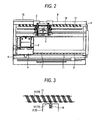
- reference numeral 1 denotes an electric stapler
- 2 denotes a driver unit
- 3 denotes a clincher unit
- 4 denotes a guide sleeve
- 5 denotes a guide sleeve
- 6 denotes a frame
- 7 denotes a guide rod
- 8 denotes a guide rod
- 9 denotes a drive shaft
- 10 denotes a drive shaft
- 11 denotes a helical groove
- 12 denotes an engaging piece
- 13 denotes an engaging piece
- 14 denotes a paper passage
- 15 denotes a stopper
- 16 denotes a spring.
- Fig. 1 shows an electric stapler which is incorporated in a business machine such as a copying machine, a printing machine, a facsimile machine, etc. for the purpose of automatically binding a determined number of sheets of paper which have been copied, printed or received by facsimile.
- the electric stapler 1 comprises: a driver unit 2 having a magazine in which a number of staples are charged, a driver plate for ejecting the staples in the magazine against the sheets of paper to be bound, and a drive mechanism for driving the driver plate; and a clincher unit 3 having a movable clincher mechanism for folding legs of the staple which have passed the sheets of paper to be bound along a back face of the sheets of paper, and a drive mechanism for driving the clincher mechanism.
- Both the units 2, 3 are integrally provided with guide sleeves 4, 5 respectively, and are held, by way of the guide sleeves 4, 5, on guide rods 7, 8 which are bridged between two frames 6. formed on opposite sides in the business machine so as to freely slide.
- Drive shafts 9, 10 for moving the units 2, 3 along the guide rods 7, 8 are disposed between the frames 6 on the opposite sides, in parallel to the guide rods 7, 8 which guide the driver unit 2 and the clincher unit 3 in a slidable. manner.
- Helical grooves 11 having a same pitch are provided on respective outer peripheral walls of the drive shafts 9, 10.
- the driver unit 2 and the clincher unit 3 are respectively provided with engaging pieces 12, 13 which are projected toward the relevant drive shafts 9, 10.
- the engaging pieces 12, 13 are engaged with the above mentioned helical grooves 11, so that they can be moved along the guide rods 7, 8 with rotation of the drive shafts 9, 10 thereby to conduct stapling performance at a desired position of the sheets of paper to be bound.
- Rotation angles and rotation speeds of the drive shafts 9, 10 for moving the driver unit 2 and the clincher unit 3 are synchronous with each other, and the driver unit 2 and the clincher unit 3 are moved on the guide rods 7, 8 in the same direction in a state where they are aligned with each other in a vertical direction. In this manner, the position of the staple which has been ejected from the driver unit 2 and the position of the clincher unit 3 will not be displaced from each other, and the stapling performance can be reliably conducted at the desired position to which the units have moved.
- the helical grooves 11 formed on the outer peripheral faces .of the drive shafts 9, 10 have a substantially trapezoidal shape in a sectional view in such a manner that a bottom part of the groove becomes narrow, as shown in Fig. 5, in order to reliably transmit the rotation of the drive shafts to the directions of moving the units 2, 3.
- the driver unit 2 and the clincher unit 3 are opposed to each other having a distance therebetween in a vertical direction, interposing a paper passage 14 through which the sheets of paper to be bound which have been treated by the copying machine or the like are adapted to pass.
- the driver unit 2 and the clincher unit 3 are respectively driven in order to conduct the stapling performance at a determined position of the sheets of paper to be bound which have been fed to the paper passage 14 formed between the two units 2, 3.
- Controls for moving the two units 2, 3 to the stapling position and driving the driver unit 2 and the clincher unit 3 to conduct the stapling performance on the sheets of paper to be bound are conducted by a control device which is provided on the business machine such as the copying machine, at the same time with controls of the treatments such as copying, and feeding and discharging processes of the sheets of paper.
- a stopper 15 is formed at one side in a moving range of the clincher unit 3 for the purpose of restricting the moving range of the clincher unit 3 in a direction of the one side.
- the clincher unit 3 is restrained from moving and stopped.
- the engaging pieces 12, 1.3 which are respectively provided in the driver unit 2 and the clincher unit 3 and adapted to be engaged with the helical grooves 11 of the drive shafts 9, 10 are urged by springs 16 so as to project from the respective units 2, 3 toward the drive shafts 9, 10.
- springs 16 By action of these springs 16, tip ends of the engaging pieces 12, 13 will be engaged with the helical grooves 11 so as to be received therein.
- the drive shafts 9, 10 are driven to rotate, and the driver unit 2 and the clincher unit 3 are moved toward the one side in the state where they are vertically aligned with each other.
- the engaging piece 13 of the clincher unit 3 will retreat into the clincher unit 3 along with further rotation of the drive shaft 10, resisting the urging force of the spring 16, thereby to be disengaged from the helical groove 11.
- the helical groove 11 has a trapezoidal shape in a sectional view as described above, the engaging piece 13 can be easily disengaged from the helical groove 11.
- the driver unit 2 further moves toward the one side by the rotation of the drive shaft 9 until it stops at the end of the moving range, since no stopper is provided. at the one side.
- the vertical alignment between the driver unit 2 and the clincher unit 3 will be released. Because the driver unit 2 will be further moved up to the one side beyond the clincher unit 3, a space will be created on an upper face of the driver unit 2, which will facilitate operation for recharging the staples into the magazine of the driver unit 2 and the work for removing the jammed staples in the staple passage at the front end of the magazine of the driver unit 2.
- the drive shafts 9, 10 are rotated in a reverse direction to drive both the units 2, 3 to the ends at the opposite side and manage the engaging piece 13 of the clincher unit 3 to be engaged again with the helical groove 11 of the drive shaft 10, at the determined position.
- the engaging piece 13 of the clincher unit 3 will be moved toward the other side preceding the driver unit 2, and stopped at the home position which is formed at the other end. Then, the engaging piece 13 will be disengaged from the helical groove 11.
- the driver unit 2 will be moved to the home position.
- the engaging piece 13 of the clincher unit 3 will be engaged with the helical groove 11 of the drive shaft 10 at the original position, whereby the driver unit 2 and the clincher unit 3 become able to move together in the state vertically aligned with each other, and can conduct the stapling performance after they have moved to a desired position.
- the stapler may be constructed in such a manner that while the driver unit 2 is stopped by the stopper, the clincher unit 3 can further move toward in a direction of the one side.
- the stopping position of the driver unit 2, where the works for charging the staples and removing the jammed staples are operated is set so that the driver unit 2 can move to an inner side of the moving range than the stopping position of the clincher unit 3 which is arranged above the driver unit.
- a large space can be created above the magazine of the driver unit 2, and it is possible to easily conduct the works for charging the staples and removing the jammed staples, without being hindered by the clincher unit 3.
Landscapes
- Engineering & Computer Science (AREA)
- Mechanical Engineering (AREA)
- Life Sciences & Earth Sciences (AREA)
- Forests & Forestry (AREA)
- Dovetailed Work, And Nailing Machines And Stapling Machines For Wood (AREA)
- Portable Nailing Machines And Staplers (AREA)
Abstract
Description
Claims (7)
- A built-in stapler built into a machine comprising:wherein said driver unit and said clincher unit are respectively constructed independently from each other,a driver unit that ejects staples charged in a magazine of the built-in stapler, against sheets of paper to be bound by means of a motor driven driver; anda clincher unit that folds legs of the staples passed the sheets of paper to be bound, along a back face of the sheets of paper,said driver unit and said clincher unit are held with a determined distance therebetween so as to move respectively, andstopping positions at one ends of respective moving ranges of said driver unit and said clincher unit are set to be displaced from each other, and the stopping position of either one of said driver unit and said clincher unit is provided at an inner side in the moving range than the stopping position of the other unit.
- The built-in stapler according to claim 1, further comprising a stopper that restricts the moving range of either one of said driver unit and said clincher unit.
- The built-in stapler according to claim 1, further comprising:a first drive shaft including a first helical groove on its outer peripheral face and adapted to move said driver unit;a second drive shaft including a second helical groove on its outer peripheral face and adapted to move said clincher unit;a first engaging piece, provided in said driver unit, movably projecting toward said first drive shaft, and adapted to be engaged with said first helical groove; anda second engaging piece, provided in said clincher unit, movably projecting toward said second drive shaft, and adapted to be engaged with said second helical groove.
- The built-in stapler according to claim 3, wherein said first helical groove and said second helical groove are formed to have such a sectional shape that bottom parts of the respective grooves become narrow.
- The built-in stapler according to claim 3, further comprising a stopper for restricting the moving range of either one of said driver unit and said clincher unit.
- The built-in stapler according to claim 5, wherein said first engaging piece is disengaged from said first helical groove, when said driver unit is stopped by said stopper.
- The built-in stapler according to claim 5, wherein said second engaging piece is disengaged from said second helical groove, when said clincher unit is stopped by said stopper.
Applications Claiming Priority (3)
| Application Number | Priority Date | Filing Date | Title |
|---|---|---|---|
| JP2001275405A JP4748293B2 (en) | 2001-09-11 | 2001-09-11 | Built-in stapler |
| JP2001275405 | 2001-09-11 | ||
| PCT/JP2002/009229 WO2003022539A1 (en) | 2001-09-11 | 2002-09-10 | Built-in equipment type stapler |
Publications (4)
| Publication Number | Publication Date |
|---|---|
| EP1426154A1 true EP1426154A1 (en) | 2004-06-09 |
| EP1426154A8 EP1426154A8 (en) | 2004-09-15 |
| EP1426154A4 EP1426154A4 (en) | 2007-09-26 |
| EP1426154B1 EP1426154B1 (en) | 2009-08-26 |
Family
ID=19100273
Family Applications (1)
| Application Number | Title | Priority Date | Filing Date |
|---|---|---|---|
| EP02765475A Expired - Lifetime EP1426154B1 (en) | 2001-09-11 | 2002-09-10 | Built-in equipment type stapler |
Country Status (8)
| Country | Link |
|---|---|
| US (1) | US6974066B2 (en) |
| EP (1) | EP1426154B1 (en) |
| JP (1) | JP4748293B2 (en) |
| KR (1) | KR100662925B1 (en) |
| CN (1) | CN100376371C (en) |
| DE (1) | DE60233510D1 (en) |
| TW (1) | TW564213B (en) |
| WO (1) | WO2003022539A1 (en) |
Families Citing this family (4)
| Publication number | Priority date | Publication date | Assignee | Title |
|---|---|---|---|---|
| US7902257B2 (en) * | 2002-04-01 | 2011-03-08 | University Of Southern California | Trihydroxy polyunsaturated eicosanoid |
| JP4110855B2 (en) * | 2002-06-28 | 2008-07-02 | マックス株式会社 | Electric stapler moving mechanism |
| EP1629992B1 (en) * | 2004-08-24 | 2009-06-03 | Müller Martini Holding AG | Method for stapling printed products and stapling machine |
| JP2011131444A (en) * | 2009-12-23 | 2011-07-07 | Max Co Ltd | Stapler for saddle stitching |
Family Cites Families (14)
| Publication number | Priority date | Publication date | Assignee | Title |
|---|---|---|---|---|
| US4444491A (en) * | 1980-08-21 | 1984-04-24 | Xerox Corporation | Very high speed duplicator with finishing function |
| DE3743979C1 (en) * | 1987-12-23 | 1989-06-15 | Offermann Zeiler Schmid Bwf | Method and device for the automatic de-needling and needling of needle boards |
| JP3020970B2 (en) * | 1989-01-18 | 2000-03-15 | 株式会社リコー | Paper processing equipment |
| US5029831A (en) * | 1989-11-14 | 1991-07-09 | Xerox Corporation | Stapler indexing apparatus |
| JP2816413B2 (en) * | 1990-06-16 | 1998-10-27 | ニスカ株式会社 | Sorter with step ring mechanism |
| DE4035869A1 (en) * | 1990-11-10 | 1992-05-14 | Kodak Ag | STAPLE FOR STAPLING LEAFS |
| US5460314A (en) * | 1992-12-29 | 1995-10-24 | Max Co., Ltd. | Stapler with improved stapling precision |
| JPH08108377A (en) * | 1994-08-08 | 1996-04-30 | Nisca Corp | Stapler and bookbinding device using it |
| JP3247598B2 (en) * | 1995-11-10 | 2002-01-15 | 株式会社荏原製作所 | Granular phosphorus adsorbent and method for removing phosphorus |
| JP3473234B2 (en) * | 1995-11-16 | 2003-12-02 | ニスカ株式会社 | Stapler |
| JP3473233B2 (en) * | 1995-11-16 | 2003-12-02 | ニスカ株式会社 | Stapler |
| DE59807190D1 (en) * | 1998-05-18 | 2003-03-20 | Grapha Holding Ag | Wire stitching machine for a saddle stitcher with a saddle chain. |
| JP2000084903A (en) * | 1998-09-11 | 2000-03-28 | Minolta Co Ltd | Stapling device |
| US6641024B2 (en) * | 2000-02-08 | 2003-11-04 | Nisca Corporation | Stapling device |
-
2001
- 2001-09-11 JP JP2001275405A patent/JP4748293B2/en not_active Expired - Fee Related
-
2002
- 2002-09-10 DE DE60233510T patent/DE60233510D1/en not_active Expired - Lifetime
- 2002-09-10 CN CNB028176103A patent/CN100376371C/en not_active Expired - Fee Related
- 2002-09-10 WO PCT/JP2002/009229 patent/WO2003022539A1/en not_active Ceased
- 2002-09-10 EP EP02765475A patent/EP1426154B1/en not_active Expired - Lifetime
- 2002-09-10 KR KR1020047003537A patent/KR100662925B1/en not_active Expired - Fee Related
- 2002-09-10 US US10/488,989 patent/US6974066B2/en not_active Expired - Lifetime
- 2002-09-11 TW TW091120717A patent/TW564213B/en not_active IP Right Cessation
Also Published As
| Publication number | Publication date |
|---|---|
| US20040238589A1 (en) | 2004-12-02 |
| KR100662925B1 (en) | 2006-12-28 |
| TW564213B (en) | 2003-12-01 |
| JP4748293B2 (en) | 2011-08-17 |
| JP2005231036A (en) | 2005-09-02 |
| EP1426154B1 (en) | 2009-08-26 |
| US6974066B2 (en) | 2005-12-13 |
| EP1426154A4 (en) | 2007-09-26 |
| WO2003022539A1 (en) | 2003-03-20 |
| KR20040034724A (en) | 2004-04-28 |
| CN1553849A (en) | 2004-12-08 |
| EP1426154A8 (en) | 2004-09-15 |
| DE60233510D1 (en) | 2009-10-08 |
| CN100376371C (en) | 2008-03-26 |
Similar Documents
| Publication | Publication Date | Title |
|---|---|---|
| EP2116345B1 (en) | Electric stapler | |
| JP5870986B2 (en) | Sheet processing apparatus and image forming system | |
| JP2009190824A (en) | Sheet folding apparatus, sheet processing apparatus, image forming apparatus, and sheet folding method | |
| US6974066B2 (en) | Built-in equipment type stapler | |
| JP5151711B2 (en) | Sheet processing apparatus and image forming apparatus | |
| JP4239732B2 (en) | Electric stapler drive mechanism | |
| EP1535709B1 (en) | Electric stapler and method for binding sheets and forming a fold line | |
| JP4099130B2 (en) | Image processing apparatus, image forming system, computer program, and recording medium | |
| JP4103710B2 (en) | Electric stapler staple supply mechanism | |
| JP4184639B2 (en) | Paper processing device | |
| JPH0416392A (en) | Image formation post-processing device | |
| JP2005081520A (en) | Stapler forming and driving mechanism | |
| JP3973973B2 (en) | Paper processing apparatus and image forming system | |
| US6769592B2 (en) | Stapler | |
| JP3990240B2 (en) | Paper processing apparatus and image forming system | |
| JP2005263404A (en) | Paper post-processing apparatus and image forming system | |
| JP4044461B2 (en) | Paper processing apparatus and image forming system | |
| JP4689443B2 (en) | Recording medium post-processing apparatus and image forming apparatus | |
| JP2010058916A (en) | Sheet postprocessing device and image forming system | |
| JP5577883B2 (en) | Post-processing apparatus, image forming apparatus, and post-processing program | |
| JP3474590B2 (en) | Paper processing equipment | |
| JP3527804B2 (en) | Paper post-processing equipment | |
| JPH09309662A (en) | Sheet post-processor for image forming apparatus | |
| JP2000355456A (en) | Recording paper after-processing device of image forming device | |
| JPH10152259A (en) | Paper post-processing equipment |
Legal Events
| Date | Code | Title | Description |
|---|---|---|---|
| PUAI | Public reference made under article 153(3) epc to a published international application that has entered the european phase |
Free format text: ORIGINAL CODE: 0009012 |
|
| 17P | Request for examination filed |
Effective date: 20040311 |
|
| AK | Designated contracting states |
Kind code of ref document: A1 Designated state(s): AT BE BG CH CY CZ DE DK EE ES FI FR GB GR IE IT LI LU MC NL PT SE SK TR |
|
| AX | Request for extension of the european patent |
Extension state: AL LT LV MK RO SI |
|
| RTI1 | Title (correction) |
Free format text: BUILT-IN EQUIPMENT TYPE STAPLER |
|
| A4 | Supplementary search report drawn up and despatched |
Effective date: 20070823 |
|
| 17Q | First examination report despatched |
Effective date: 20080311 |
|
| GRAP | Despatch of communication of intention to grant a patent |
Free format text: ORIGINAL CODE: EPIDOSNIGR1 |
|
| GRAS | Grant fee paid |
Free format text: ORIGINAL CODE: EPIDOSNIGR3 |
|
| GRAA | (expected) grant |
Free format text: ORIGINAL CODE: 0009210 |
|
| AK | Designated contracting states |
Kind code of ref document: B1 Designated state(s): DE FR GB IT NL SE |
|
| REG | Reference to a national code |
Ref country code: GB Ref legal event code: FG4D |
|
| REF | Corresponds to: |
Ref document number: 60233510 Country of ref document: DE Date of ref document: 20091008 Kind code of ref document: P |
|
| REG | Reference to a national code |
Ref country code: SE Ref legal event code: TRGR |
|
| PLBE | No opposition filed within time limit |
Free format text: ORIGINAL CODE: 0009261 |
|
| STAA | Information on the status of an ep patent application or granted ep patent |
Free format text: STATUS: NO OPPOSITION FILED WITHIN TIME LIMIT |
|
| 26N | No opposition filed |
Effective date: 20100527 |
|
| PGFP | Annual fee paid to national office [announced via postgrant information from national office to epo] |
Ref country code: IT Payment date: 20120915 Year of fee payment: 11 |
|
| PG25 | Lapsed in a contracting state [announced via postgrant information from national office to epo] |
Ref country code: IT Free format text: LAPSE BECAUSE OF NON-PAYMENT OF DUE FEES Effective date: 20130910 |
|
| REG | Reference to a national code |
Ref country code: FR Ref legal event code: PLFP Year of fee payment: 15 |
|
| REG | Reference to a national code |
Ref country code: FR Ref legal event code: PLFP Year of fee payment: 16 |
|
| PGFP | Annual fee paid to national office [announced via postgrant information from national office to epo] |
Ref country code: NL Payment date: 20170814 Year of fee payment: 16 |
|
| PGFP | Annual fee paid to national office [announced via postgrant information from national office to epo] |
Ref country code: DE Payment date: 20170905 Year of fee payment: 16 Ref country code: FR Payment date: 20170810 Year of fee payment: 16 Ref country code: GB Payment date: 20170906 Year of fee payment: 16 |
|
| PGFP | Annual fee paid to national office [announced via postgrant information from national office to epo] |
Ref country code: SE Payment date: 20170912 Year of fee payment: 16 |
|
| REG | Reference to a national code |
Ref country code: DE Ref legal event code: R119 Ref document number: 60233510 Country of ref document: DE |
|
| REG | Reference to a national code |
Ref country code: SE Ref legal event code: EUG |
|
| REG | Reference to a national code |
Ref country code: NL Ref legal event code: MM Effective date: 20181001 |
|
| GBPC | Gb: european patent ceased through non-payment of renewal fee |
Effective date: 20180910 |
|
| PG25 | Lapsed in a contracting state [announced via postgrant information from national office to epo] |
Ref country code: SE Free format text: LAPSE BECAUSE OF NON-PAYMENT OF DUE FEES Effective date: 20180911 |
|
| PG25 | Lapsed in a contracting state [announced via postgrant information from national office to epo] |
Ref country code: NL Free format text: LAPSE BECAUSE OF NON-PAYMENT OF DUE FEES Effective date: 20181001 |
|
| PG25 | Lapsed in a contracting state [announced via postgrant information from national office to epo] |
Ref country code: DE Free format text: LAPSE BECAUSE OF NON-PAYMENT OF DUE FEES Effective date: 20190402 |
|
| PG25 | Lapsed in a contracting state [announced via postgrant information from national office to epo] |
Ref country code: FR Free format text: LAPSE BECAUSE OF NON-PAYMENT OF DUE FEES Effective date: 20180930 |
|
| PG25 | Lapsed in a contracting state [announced via postgrant information from national office to epo] |
Ref country code: GB Free format text: LAPSE BECAUSE OF NON-PAYMENT OF DUE FEES Effective date: 20180910 |