EP1425535B1 - Cardanic suspension device for a camera balance device - Google Patents
Cardanic suspension device for a camera balance device Download PDFInfo
- Publication number
- EP1425535B1 EP1425535B1 EP02760331A EP02760331A EP1425535B1 EP 1425535 B1 EP1425535 B1 EP 1425535B1 EP 02760331 A EP02760331 A EP 02760331A EP 02760331 A EP02760331 A EP 02760331A EP 1425535 B1 EP1425535 B1 EP 1425535B1
- Authority
- EP
- European Patent Office
- Prior art keywords
- suspension device
- cardanic suspension
- axis
- hinge
- sub
- Prior art date
- Legal status (The legal status is an assumption and is not a legal conclusion. Google has not performed a legal analysis and makes no representation as to the accuracy of the status listed.)
- Expired - Lifetime
Links
- 239000000725 suspension Substances 0.000 title claims abstract description 60
- 239000002184 metal Substances 0.000 claims description 5
- 239000004033 plastic Substances 0.000 claims description 5
- 239000000919 ceramic Substances 0.000 claims description 4
- 239000002131 composite material Substances 0.000 claims description 4
- 238000006073 displacement reaction Methods 0.000 claims description 4
- 239000000463 material Substances 0.000 claims description 4
- 230000033001 locomotion Effects 0.000 description 11
- 238000010276 construction Methods 0.000 description 4
- 238000011161 development Methods 0.000 description 3
- 230000018109 developmental process Effects 0.000 description 3
- 230000005484 gravity Effects 0.000 description 2
- 230000002411 adverse Effects 0.000 description 1
- 230000002950 deficient Effects 0.000 description 1
- 230000001419 dependent effect Effects 0.000 description 1
- 238000004146 energy storage Methods 0.000 description 1
- 238000003780 insertion Methods 0.000 description 1
- 230000037431 insertion Effects 0.000 description 1
- 230000003993 interaction Effects 0.000 description 1
- 239000000758 substrate Substances 0.000 description 1
Images


Classifications
-
- F—MECHANICAL ENGINEERING; LIGHTING; HEATING; WEAPONS; BLASTING
- F16—ENGINEERING ELEMENTS AND UNITS; GENERAL MEASURES FOR PRODUCING AND MAINTAINING EFFECTIVE FUNCTIONING OF MACHINES OR INSTALLATIONS; THERMAL INSULATION IN GENERAL
- F16M—FRAMES, CASINGS OR BEDS OF ENGINES, MACHINES OR APPARATUS, NOT SPECIFIC TO ENGINES, MACHINES OR APPARATUS PROVIDED FOR ELSEWHERE; STANDS; SUPPORTS
- F16M13/00—Other supports for positioning apparatus or articles; Means for steadying hand-held apparatus or articles
- F16M13/04—Other supports for positioning apparatus or articles; Means for steadying hand-held apparatus or articles for supporting on, or holding steady relative to, a person, e.g. by chains, e.g. rifle butt or pistol grip supports, supports attached to the chest or head
-
- F—MECHANICAL ENGINEERING; LIGHTING; HEATING; WEAPONS; BLASTING
- F16—ENGINEERING ELEMENTS AND UNITS; GENERAL MEASURES FOR PRODUCING AND MAINTAINING EFFECTIVE FUNCTIONING OF MACHINES OR INSTALLATIONS; THERMAL INSULATION IN GENERAL
- F16M—FRAMES, CASINGS OR BEDS OF ENGINES, MACHINES OR APPARATUS, NOT SPECIFIC TO ENGINES, MACHINES OR APPARATUS PROVIDED FOR ELSEWHERE; STANDS; SUPPORTS
- F16M11/00—Stands or trestles as supports for apparatus or articles placed thereon Stands for scientific apparatus such as gravitational force meters
- F16M11/02—Heads
- F16M11/04—Means for attachment of apparatus; Means allowing adjustment of the apparatus relatively to the stand
- F16M11/06—Means for attachment of apparatus; Means allowing adjustment of the apparatus relatively to the stand allowing pivoting
- F16M11/08—Means for attachment of apparatus; Means allowing adjustment of the apparatus relatively to the stand allowing pivoting around a vertical axis, e.g. panoramic heads
-
- F—MECHANICAL ENGINEERING; LIGHTING; HEATING; WEAPONS; BLASTING
- F16—ENGINEERING ELEMENTS AND UNITS; GENERAL MEASURES FOR PRODUCING AND MAINTAINING EFFECTIVE FUNCTIONING OF MACHINES OR INSTALLATIONS; THERMAL INSULATION IN GENERAL
- F16M—FRAMES, CASINGS OR BEDS OF ENGINES, MACHINES OR APPARATUS, NOT SPECIFIC TO ENGINES, MACHINES OR APPARATUS PROVIDED FOR ELSEWHERE; STANDS; SUPPORTS
- F16M11/00—Stands or trestles as supports for apparatus or articles placed thereon Stands for scientific apparatus such as gravitational force meters
- F16M11/20—Undercarriages with or without wheels
- F16M11/2007—Undercarriages with or without wheels comprising means allowing pivoting adjustment
- F16M11/2021—Undercarriages with or without wheels comprising means allowing pivoting adjustment around a horizontal axis
-
- F—MECHANICAL ENGINEERING; LIGHTING; HEATING; WEAPONS; BLASTING
- F16—ENGINEERING ELEMENTS AND UNITS; GENERAL MEASURES FOR PRODUCING AND MAINTAINING EFFECTIVE FUNCTIONING OF MACHINES OR INSTALLATIONS; THERMAL INSULATION IN GENERAL
- F16M—FRAMES, CASINGS OR BEDS OF ENGINES, MACHINES OR APPARATUS, NOT SPECIFIC TO ENGINES, MACHINES OR APPARATUS PROVIDED FOR ELSEWHERE; STANDS; SUPPORTS
- F16M13/00—Other supports for positioning apparatus or articles; Means for steadying hand-held apparatus or articles
-
- F—MECHANICAL ENGINEERING; LIGHTING; HEATING; WEAPONS; BLASTING
- F16—ENGINEERING ELEMENTS AND UNITS; GENERAL MEASURES FOR PRODUCING AND MAINTAINING EFFECTIVE FUNCTIONING OF MACHINES OR INSTALLATIONS; THERMAL INSULATION IN GENERAL
- F16M—FRAMES, CASINGS OR BEDS OF ENGINES, MACHINES OR APPARATUS, NOT SPECIFIC TO ENGINES, MACHINES OR APPARATUS PROVIDED FOR ELSEWHERE; STANDS; SUPPORTS
- F16M2200/00—Details of stands or supports
- F16M2200/04—Balancing means
- F16M2200/041—Balancing means for balancing rotational movement of the head
Definitions
- the present invention relates to a gimbal suspension device for a camera balance device according to the preamble of claim 1.
- Such camera balance devices are used for balancing video and film cameras, which are manually guided by a cameraman and are connected via a suspension device, for example, with a spring arm of a west-facing support device (so-called body stand), which in turn is attached to the body of the cameraman ,
- the suspension is intended to prevent tilting and tilting movements and vibrations and step movements from the body of the cameraman transmitted to the camera, because it should always ensure a consistent orientation of the camera and tilting, tilting or swinging the camera can be avoided.
- the attached to the balance device camera can be attached by means of the suspension on a tripod, dolly, crane, etc., the suspension can then prevent, for example, unevenness of the substrate affect the position of the camera.
- the suspension is designed so that the construction of camera and balance system with respect to the tripod can perform a pendulum motion.
- This structure is also associated with counterweights. With appropriate choice and positioning of these counterweights, the camera is balanced so that tilting and tilting movements, Vibrations and step movements not from the body tripod, stand, dolly, crane or similar. transferred to the camera.
- the camera is attached to one end of a pendulum arm, at the other end of the counterweights are attached.
- counterweights for example, batteries are used, which also serve as energy storage.
- the pendulum arm is connected to a gimbal suspension device, which in turn can be attached, for example, to a spring arm of a body stand, a tripod, Dolly or crane.
- the suspension device has two intersecting joint axes (gimbal axes), of which one vertically (vertically) and the other horizontally in operation, and a rotation axis by the vertical Joint axis runs and is perpendicular to the horizontal hinge axis.
- a hinged output-side fastener is rotatable about the vertical hinge axis and serves to secure the gimbal to the pendulum arm of the camera balance device, and a hinge-side fastener rotatable about the pivot serves to secure the gimbal to a tripod, in particular the above-mentioned body tripod or on a stand.
- US 5,797,054 A discloses a cardanic suspension device according to the preamble of claim 1.
- the object underlying the present invention is to provide an improved gimbal suspension for a camera balance device in which the balance adjustment is maintained over a wide range of motion of the camera.
- a centering device is provided between the joint input side and the hinge output side fixing member, with which the vertical hinge axis and the axis of rotation are relative to each other spatially variable.
- the vertical hinge axis and the rotation axis can therefore be shifted against each other until the axis of rotation exactly intersects the vertical joint axis.
- the invention is based on the finding that the smallest deviations in the centering of the joint input side with respect to the joint output-side fastening element lead to significant influences on the balance set by means of the counterweights. Such deviations in the centering lead to significant errors in the camera, especially when it is done at higher speeds.
- the centering is made possible by the displaceability of the axis of rotation with respect to the vertical joint axis.
- the centering according to the invention ensures that a balance set by means of the counterweights is maintained, for example, even when the camera assembly rotates through 360 ° with respect to the stand or the cameraman makes a movement over 360 ° with the suspension device. If the centering is not accurate, even at rotations of less than 180 °, balance deviations occur at certain points, which lead to defective camera guidance, especially in the case of fast movements.
- the vertical hinge axis along the axis extension of the horizontal hinge axis is displaceable.
- the displacement of the vertical hinge axis can be done by means of at least one screw.
- a particularly preferred embodiment has two setscrews whose longitudinal axes extend along the horizontal hinge axis.
- the suspension device according to the invention can also have a second centering device in the region of the vertical and horizontal articulation axis, by means of which the relative position between the output-side fastening element and the camera balance device can be fixed without play in this area.
- the centering is done in two ways: by means of a centering device, which is preferably formed by two setscrews, the vertical hinge axis and the rotation axis with respect to each other are displaceable, preferably along the horizontal hinge axis.
- the second centering device in addition, the relative position between the joint-output-side fastening element and the camera balance device in the region of the two joint axes can be determined without play.
- the attachment of the output-side fastening element to the camera balance device is preferably carried out by means of a clamping device which is arranged so that the clamping device and the second centering device are located at spaced-apart locations and preferably at opposite ends of the hinge-side fastening element.
- the clamping device for the attachment of the suspension device to the pendulum arm of the camera balance device is then located as far away from the gimbal, so that the clamping operation can not lead to a decentralization of the universal joint with respect to the three axes.
- the joint input side and / or the joint output side fastening element are designed as a handle.
- the joint-input-side handle By means of the joint-input-side handle, the suspension device on a spring arm of the cameraman's vest, a tripod o.ä. be attached.
- the joint output side handle is used in addition to the handling and the placement of the suspension on the pendulum arm of the camera balance device.
- the second centering device can be configured adjustable, preferably infinitely adjustable.
- the joint output-side fastening element is designed as a straight piece of pipe.
- it can slide over the appropriately designed pendulum arm of the camera balance device.
- the suspension device is slidably disposed on the camera balance device or on the pendulum arm in order to make a change in position with respect to the camera and counterweights.
- the pipe section can, for example, have a circular cross-section. Also conceivable is a rectangular or square configuration.
- the second centering device is formed in an advantageous embodiment by an adjusting ring, which is provided with a clamping cone, which in turn cooperates with a clamping ring.
- the hinge-side fixing element is configured as a pipe section with a circular cross section, as described above, the adjusting ring can be screwed into one end of the pipe section and cooperate with a clamping ring arranged on the camera balance device.
- the clamping ring is preferably made of plastic. However, it may also be made of metal, ceramic, a composite material or a combination of these materials. Preferably, at least one slot is formed therein to increase deformability and adaptability to the pendulum arm of the camera balance device extending therein.
- the adjusting ring in turn is preferably made of metal, but may also consist of plastic, ceramic, a composite material or a combination of these materials.
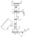
- FIG. 1 shows a camera balance device 1 together with a gimbal suspension device 3 according to the invention.
- the camera balance device has a pendulum tube 5.
- a camera mounting device 7 which consists essentially of a base 9 and a holding plate 11 on which a camera can be attached, wherein the holding plate 11 relative to the base 9 via screws 13 (of which only here a visible) is displaceable, in the drawing plane of Fig. 1 in or out of this plane. Further adjusting screws (not shown) are provided to the holding plate 11 with respect to the base 9 to the right and left in Fig. 1 to move.
- a receiving device 15 for counterweights.
- a monitor holder 17 is provided and two carrier plates 19, 19 "for receiving counterweights, which are formed by accumulators, for example.
- the carrier plate 19 is slidably and fixably attached to sliding tubes 21 (only one of which is visible) also pivotable relative to the sliding tube 21, the locking of the support plate 19 in the desired angular position by means of a clamping lever 23rd
- This suspension device 3 is shown in more detail in FIGS. 2 to 4 and has a first handle 25 as a hinge-side fastening element and a second handle 27 as a joint-output-side fastening element.
- the first handle 25 serves to attach the suspension device to a tripod, in particular to a body stand, which is worn by a cameraman.
- the second handle 27 is used for attaching the suspension device 3 to the camera balance device 1.
- the second handle 27 is tubular and arranged around the pendulum tube 5 of the camera balance device 1 around, so that it with respect to the pendulum tube 5 slidably is.
- a cameraman by means of the first handle 25, for example, on a Guide spring arm of a body tripod, a tripod, dolly or crane attached construction ambidextrous.
- the first handle 25 is connected to a fork member 31 so that it is rotatable with respect to this fork member 31 about a rotation axis D, the longitudinal axis of a straight, in Fig. 1 horizontally extending portion of the first handle 25 corresponds.
- the fork element 31 is in turn pivotally connected to a hinge outer ring 33 about a horizontal hinge axis G 1 (first gimbal axis).
- This hinge outer ring 33 is in turn rotatably connected about a vertical articulation axis G 2 (second gimbal axis) with a hinge inner ring 35, which in turn is fixedly connected to the second handle 27 which is connected to the pendulum tube 5 of the camera via the clamping device 29.
- Balance device 1 is attached.
- the articulated suspension device 3 By means of the articulated suspension device 3, it is now to be prevented that movements of the stand, for example of the body stand, are transmitted to the camera mounted on the holding plate 11.
- the construction of pendulum tube 5, camera holding device 7 and counterweights on the receiving device 15 must be positioned balance-balanced.
- the camera balance device 1 has a variety of settings. In particular, the. Balance of the system by the provision of different heavy counterweights on the receiving device 15th achieved.
- the support plate 19 is pivotally and displaceably mounted for counterweights. The same can apply to the monitor holding device 17.
- the illustrated embodiment has as a receiving device 15 for counterweights the monitor bracket 17 and two support plates 19, 19 ", as well as it is of course conceivable to provide 5 more attachment options for counterweights at different points of the pendulum tube.
- the center of gravity of the camera 11 located on the holding plate 11 can also be displaced relative to the base 9 connected to the pendulum tube 5 by means of the adjusting screws 13. An even more flexible system is created when the pendulum tube 5 is designed to be telescopic.
- Fig. 3 illustrates this centering device 37, which is provided in the region of the two intersecting joint axes G 1 and G 2 .
- the centering device 37 and the clamping device 29, which serves to attach the second handle 27 to the pendulum tube 5, are therefore located At the opposite ends of the second handle 27.
- the centering device 37 has a threaded adjusting ring 39, which is screwed into the joint inner ring 35.
- the centering device 37 is infinitely adjustable due to the thread.
- This collar 39 is internally provided with a cone which presses on a counter-cone of a slotted clamping ring 41 made of plastic, which is provided on the pendulum tube 5. The centering of the two elements is therefore effected by the interaction of the cone 'of the adjusting ring 39 with the cone of the clamping ring 41.
- the adjusting ring 39 is in turn preferably made of metal.
- both the clamping device 29 and the centering device 37 are also easily accessible.
- the suspension device 3 according to the invention also has a further centering device 43, which will now be described with reference to FIG. 4.
- This further centering device 43 serves to move the vertical articulation axis G2 relative to the axis of rotation D and thus to center the pendulum tube 5 of the camera balance device 1 with respect to the fork element 31 of the suspension device 3 according to the invention.
- this centering device 43 is realized by two setscrews 47, which are screwed by means of very finely threaded in the fork member 31 and also pivotally mounted with respect to the hinge outer ring 33. These screws thus realize the connection of the fork member 31 with the hinge outer ring 33.
- the screws 47 have insertion openings 45 for a tool.
- One of the two screws 47 can also be replaced by a spring thrust bearing.
- the centering device 43 thus provides, in addition to the centering device 37, a further improvement in the alignment of the suspension device 3 according to the invention with respect to the camera balance device 1.
Abstract
Description
Die vorliegende Erfindung betrifft eine kardanische Aufhängevorrichtung für eine Kamera-Balance-Vorrichtung gemäß dem Oberbegriff des Anspruchs 1.The present invention relates to a gimbal suspension device for a camera balance device according to the preamble of claim 1.
Solche Kamera-Balance-Vorrichtungen dienen zum Ausbalancieren von Video- und Filmkameras, die von einem Kameramann manuell geführt werden und dabei über eine Aufhängevorrichtung beispielsweise mit einem Federarm einer westenartigen Tragvorrichtung (sog. Körperstativ) verbunden sind, die ihrerseits am Körper des Kameramanns befestigt wird.Such camera balance devices are used for balancing video and film cameras, which are manually guided by a cameraman and are connected via a suspension device, for example, with a spring arm of a west-facing support device (so-called body stand), which in turn is attached to the body of the cameraman ,
Die Aufhängevorrichtung soll dabei verhindern, dass sich Neige- und Kippbewegungen sowie Schwingungen und Schrittbewegungen von dem Körper des Kameramanns auf die Kamera übertragen, denn es sollte stets eine gleichbleibende Ausrichtung der Kamera gewährleistet und ein Neigen, Kippen oder Schwingen der Kamera vermieden werden. Alternativ kann die an der Balance-Vorrichtung angebrachte Kamera mittels der Aufhängevorrichtung auch an einem Standstativ, Dolly, Kran etc. befestigt werden, wobei die Aufhängevorrichtung dann verhindern kann, dass sich beispielsweise Unebenheiten des Untergrunds auf die Lage der Kamera auswirken.The suspension is intended to prevent tilting and tilting movements and vibrations and step movements from the body of the cameraman transmitted to the camera, because it should always ensure a consistent orientation of the camera and tilting, tilting or swinging the camera can be avoided. Alternatively, the attached to the balance device camera can be attached by means of the suspension on a tripod, dolly, crane, etc., the suspension can then prevent, for example, unevenness of the substrate affect the position of the camera.
Dazu ist die Aufhängevorrichtung so ausgestaltet, dass der Aufbau aus Kamera und Balancesystem bezüglich des Stativs eine Pendelbewegung ausführen kann. Dieser Aufbau ist darüber hinaus mit Kontergewichten verbunden. Bei geeigneter Wahl und Positionierung dieser Kontergewichte wird die Kamera so ausbalanciert, dass sich Neige- und Kippbewegungen, Schwingungen und Schrittbewegungen nicht von dem Körperstativ, Standstativ, Dolly, Kran o.ä. auf die Kamera übertragen.For this purpose, the suspension is designed so that the construction of camera and balance system with respect to the tripod can perform a pendulum motion. This structure is also associated with counterweights. With appropriate choice and positioning of these counterweights, the camera is balanced so that tilting and tilting movements, Vibrations and step movements not from the body tripod, stand, dolly, crane or similar. transferred to the camera.
Bei einer bekannten Kamera-Balance-Vorrichtung ist die Kamera an einem Ende eines Pendelarms angebracht, an dessen anderem Ende die Kontergewichte befestigt sind. Als Kontergewichte werden beispielsweise Akkus verwendet, die gleichzeitig als Energiespeicher dienen.In a known camera balance device, the camera is attached to one end of a pendulum arm, at the other end of the counterweights are attached. As counterweights, for example, batteries are used, which also serve as energy storage.
Der Pendelarm ist mit einer kardanischen Aufhängevorrichtung verbunden, die ihrerseits beispielsweise an einem Federarm eines Körperstativs, einem Stativ, Dolly oder Kran befestigbar ist.The pendulum arm is connected to a gimbal suspension device, which in turn can be attached, for example, to a spring arm of a body stand, a tripod, Dolly or crane.
In der kardanischen Aufhängung des Kameraaufbaus bezüglich des Stativs sind dabei drei Bewegungsachsen realisiert: Die Aufhängevorrichtung weist zwei einander kreuzende Gelenkachsen (Kardanachsen) auf, von denen im Betrieb eine vertikal (lotrecht) und die andere horizontal verläuft, sowie eine Drehachse, die durch die vertikale Gelenkachse verläuft und senkrecht zur horizontalen Gelenkachse liegt. Ein gelenkausgangsseitiges Befestigungselement ist um die vertikale Gelenkachse drehbar und dient zum Befestigen der kardanischen Aufhängevorrichtung an dem Pendelarm der Kamera-Balance-Vorrichtung, und ein gelenkeingangsseitiges Befestigungselement, das um die Drehachse drehbar ist, dient zum Befestigen der kardanischen Aufhängevorrichtung an einem Stativ, insbesondere an dem oben genannten Körperstativ oder auch an einem Standstativ.In the gimbal mounting of the camera body with respect to the tripod three axes of movement are realized: The suspension device has two intersecting joint axes (gimbal axes), of which one vertically (vertically) and the other horizontally in operation, and a rotation axis by the vertical Joint axis runs and is perpendicular to the horizontal hinge axis. A hinged output-side fastener is rotatable about the vertical hinge axis and serves to secure the gimbal to the pendulum arm of the camera balance device, and a hinge-side fastener rotatable about the pivot serves to secure the gimbal to a tripod, in particular the above-mentioned body tripod or on a stand.
US 5,797,054 A offenbart eine kardanische Aufhängevorrichtung gemäß dem Oberbegriff des Patentanspruchs 1.US 5,797,054 A discloses a cardanic suspension device according to the preamble of claim 1.
Die der vorliegenden Erfindung zugrunde liegende Aufgabe liegt darin, eine verbesserte kardanische Aufhängung für eine Kamera-Balance-Vorrichtung zu schaffen, bei der die Balanceeinstellung über einen weiten Bewegungsbereich der Kamera aufrecht erhalten bleibt.The object underlying the present invention is to provide an improved gimbal suspension for a camera balance device in which the balance adjustment is maintained over a wide range of motion of the camera.
Diese Aufgabe wird gelöst durch eine kardanische Aufhängevorrichtung gemäß dem Patentanspruch 1. Demzufolge ist zwischen dem gelenkeingangsseitigen und dem gelenkausgangsseitigen Befestigungselement eine zentriereinrichtung vorgesehen, mit der die vertikale Gelenkachse und die Drehachse relativ zueinander ortsveränderbar sind. Die vertikale Gelenkachse und die Drehachse können daher gegeneinander verschoben werden, bis die Drehachse die vertikale Gelenksachse exakt schneidet.This object is achieved by a gimbal suspension device according to claim 1. Accordingly, a centering device is provided between the joint input side and the hinge output side fixing member, with which the vertical hinge axis and the axis of rotation are relative to each other spatially variable. The vertical hinge axis and the rotation axis can therefore be shifted against each other until the axis of rotation exactly intersects the vertical joint axis.
Der Erfindung liegt die Erkenntnis zugrunde, dass kleinste Abweichungen in der Zentrierung des gelenkeingangsseitigen bezüglich des gelenkausgangsseitigen Befestigungselements zu erheblichen Beeinflussungen der mittels der Kontergewichte eingestellten Balance führen. Solche Abweichungen in der Zentrierung führen zu wesentlichen Fehlern in der Kameraführung, insbesondere wenn diese bei höheren Geschwindigkeiten erfolgt.The invention is based on the finding that the smallest deviations in the centering of the joint input side with respect to the joint output-side fastening element lead to significant influences on the balance set by means of the counterweights. Such deviations in the centering lead to significant errors in the camera, especially when it is done at higher speeds.
Daher ist es von besonderer Bedeutung, dass im Bereich des Kardangelenks, wo die beiden Gelenkachsen sowie die Drehachse zusammentreffen, eine exakte Zentrierung (im Bereich von einigen hundertstel Millimetern) der beiden Befestigungselemente bezüglich einander gewährleistet ist. Eine solche exakte Zentrierung ist bei Bauteilen mit fester relativer Position zueinander nur sehr schwierig und kostenaufwändig zu realisieren.It is therefore of particular importance that an exact centering (in the range of a few hundredths of a millimeter) of the two fastening elements with respect to each other is ensured in the area of the cardan joint, where the two joint axes and the axis of rotation coincide. Such exact centering is very difficult and costly to implement in components with fixed relative position to each other.
Erfindungsgemäß wird die Zentrierung durch die Verschiebbarkeit der Drehachse bezüglich der vertikalen Gelenkachse möglich.According to the invention, the centering is made possible by the displaceability of the axis of rotation with respect to the vertical joint axis.
Durch die erfindungsgemäße Zentrierung ist gewährleistet, dass eine mittels der Kontergewichte eingestellte Balance beispielsweise auch dann erhalten bleibt, wenn sich der Kameraaufbau um 360° bezüglich des Stativs dreht oder der Kameramann mit der Aufhängevorrichtung eine Bewegung über 360° vornimmt. Erfolgt die Zentrierung nicht genau , so treten bereits bei Drehungen um weniger als 180° an gewissen Stellen Balanceabweichungen auf, die insbesondere bei schnellen Bewegungen zu einer fehlerhaften Kameraführung führen.The centering according to the invention ensures that a balance set by means of the counterweights is maintained, for example, even when the camera assembly rotates through 360 ° with respect to the stand or the cameraman makes a movement over 360 ° with the suspension device. If the centering is not accurate, even at rotations of less than 180 °, balance deviations occur at certain points, which lead to defective camera guidance, especially in the case of fast movements.
Vorteilhafte Weiterbildungen der erfindungsgemäßen kardanischen Aufhängevorrichtung ergeben sich aus den Unteransprüchen.Advantageous developments of the gimbal suspension device according to the invention will become apparent from the dependent claims.
In einer vorteilhaften Ausgestaltung der Erfindung ist die vertikale Gelenkachse entlang der Achsenerstreckung der horizontalen Gelenkachse verschiebbar. Dabei kann die Verschiebung der vertikalen Gelenkachse mittels zumindest einer Stellschraube erfolgen. Eine besonders bevorzugte Ausführungsform weist zwei Stellschrauben auf, deren Längsachsen sich entlang der horizontalen Gelenkachse erstrecken. Ebenso ist es jedoch denkbar, nur eine Stellschraube und ein ihr gegenüberliegend angeordnetes Federdrucklager vorzusehen, so dass die Verstellung durch die Verdrehung dieser Stellschraube erfolgt.In an advantageous embodiment of the invention, the vertical hinge axis along the axis extension of the horizontal hinge axis is displaceable. In this case, the displacement of the vertical hinge axis can be done by means of at least one screw. A particularly preferred embodiment has two setscrews whose longitudinal axes extend along the horizontal hinge axis. However, it is also conceivable to provide only one adjusting screw and a spring pressure bearing arranged opposite to it, so that the adjustment takes place by the rotation of this adjusting screw.
Die erfindungsgemäße Aufhängevorrichtung kann außerdem im Bereich der vertikalen und horizontalen Gelenkachse eine zweite Zentriereinrichtung aufweisen, mittels derer die Relativposition zwischen dem ausgangsseitigen Befestigungselement und der Kamera-Balance-Vorrichtung in diesem Bereich spielfrei festlegbar ist. In diesem Fall erfolgt die Zentrierung in zweifacher Art und Weise: mittels einer Zentriereinrichtung, die vorzugsweise durch zwei Stellschrauben gebildet wird, sind die vertikale Gelenkachse und die Drehachse bezüglich einander verschiebbar, vorzugsweise entlang der horizontalen Gelenkachse. Mittels der zweiten Zentriereinrichtung kann zusätzlich die Relativposition zwischen dem gelenkausgangsseitigen Befestigungselement und der Kamera-Balance-Vorrichtung im Bereich der beiden Gelenkachsen spielfrei festgelegt werden.The suspension device according to the invention can also have a second centering device in the region of the vertical and horizontal articulation axis, by means of which the relative position between the output-side fastening element and the camera balance device can be fixed without play in this area. In this case the centering is done in two ways: by means of a centering device, which is preferably formed by two setscrews, the vertical hinge axis and the rotation axis with respect to each other are displaceable, preferably along the horizontal hinge axis. By means of the second centering device, in addition, the relative position between the joint-output-side fastening element and the camera balance device in the region of the two joint axes can be determined without play.
Die Befestigung des ausgangsseitigen Befestigungselements an der Kamera-Balance-Vorrichtung erfolgt vorzugsweise mittels einer Klemmeinrichtung, die so angeordnet ist, dass die Klemmeinrichtung und die zweite Zentriereinrichtung sich an voneinander beabstandeten Stellen und vorzugsweise an entgegengesetzten Enden des gelenkausgangsseitigen Befestigungselements befinden. Die Klemmeinrichtung für die Befestigung der Aufhängevorrichtung an dem Pendelarm der Kamera-Balance-Vorrichtung befindet sich dann möglichst weit entfernt von der kardanischen Aufhängung, damit der Klemmvorgang nicht zu einer Dezentralisierung des Kardangelenks hinsichtlich der drei Achsen führen kann.The attachment of the output-side fastening element to the camera balance device is preferably carried out by means of a clamping device which is arranged so that the clamping device and the second centering device are located at spaced-apart locations and preferably at opposite ends of the hinge-side fastening element. The clamping device for the attachment of the suspension device to the pendulum arm of the camera balance device is then located as far away from the gimbal, so that the clamping operation can not lead to a decentralization of the universal joint with respect to the three axes.
In einer vorteilhaften Weiterbildung der erfindungsgemäßen kardanischen Aufhängevorrichtung sind das gelenkeingangsseitige und/oder das gelenkausgangsseitige Befestigungselement als Handgriff ausgebildet. Mittels des gelenkeingangsseitigen Handgriffs kann die Aufhängevorrichtung an einem Federarm der Weste des Kameramanns, einem Stativ o.ä. angebracht werden. Der gelenkausgangsseitige Handgriff dient neben der Handhabung auch dem Aufsetzen der Aufhängevorrichtung auf den Pendelarm der Kamera-Balance-Vorrichtung.In an advantageous development of the gimbal suspension device according to the invention, the joint input side and / or the joint output side fastening element are designed as a handle. By means of the joint-input-side handle, the suspension device on a spring arm of the cameraman's vest, a tripod o.ä. be attached. The joint output side handle is used in addition to the handling and the placement of the suspension on the pendulum arm of the camera balance device.
Die zweite Zentriereinrichtung kann verstellbar, vorzugsweise stufenlos verstellbar ausgestaltet sein.The second centering device can be configured adjustable, preferably infinitely adjustable.
In einer vorteilhaften Weiterbildung ist das gelenkausgangsseitige Befestigungselement als gerades Rohrstück ausgebildet. Es kann in diesem Fall über den entsprechend gestalteten Pendelarm der Kamera-Balance-Vorrichtung hinüber gleiten. Vorzugsweise ist die Aufhängevorrichtung an der Kamera-Balance-Vorrichtung bzw. an dem Pendelarm verschiebbar angeordnet, um bezüglich Kamera und Gegengewichten eine Lageveränderung vorzunehmen.In an advantageous development, the joint output-side fastening element is designed as a straight piece of pipe. In this case, it can slide over the appropriately designed pendulum arm of the camera balance device. Preferably, the suspension device is slidably disposed on the camera balance device or on the pendulum arm in order to make a change in position with respect to the camera and counterweights.
Das Rohrstück kann dabei beispielsweise einen kreisförmigen Querschnitt haben. Ebenso denkbar ist eine rechteckige oder quadratische Ausgestaltung.The pipe section can, for example, have a circular cross-section. Also conceivable is a rectangular or square configuration.
Die zweite Zentriervorrichtung wird in einer vorteilhaften Ausgestaltung durch einen Stellring gebildet, der mit einem Klemmkonus versehen ist, der seinerseits mit einem Klemmring zusammenwirkt. Falls das gelenkausgangsseitige Befestigungselement, wie oben beschrieben, als Rohrstück mit kreisförmigem Querschnitt ausgestaltet ist, kann der Stellring in ein Ende des Rohrstücks einschraubbar sein und mit einem an der Kamera-Balance-Vorrichtung angeordneten Klemmring zusammenwirken.The second centering device is formed in an advantageous embodiment by an adjusting ring, which is provided with a clamping cone, which in turn cooperates with a clamping ring. If the hinge-side fixing element is configured as a pipe section with a circular cross section, as described above, the adjusting ring can be screwed into one end of the pipe section and cooperate with a clamping ring arranged on the camera balance device.
Der Klemmring besteht vorzugsweise aus Kunststoff. Er kann jedoch ebenso aus Metall, Keramik, einem Kompositmaterial oder einer Kombination aus diesen Materialien bestehen. Vorzugsweise ist zumindest ein Schlitz darin ausgebildet, um die Verformbarkeit und die Anpassbarkeit an den darin verlaufenden Pendelarm der Kamera-Balance-Vorrichtung zu steigern.The clamping ring is preferably made of plastic. However, it may also be made of metal, ceramic, a composite material or a combination of these materials. Preferably, at least one slot is formed therein to increase deformability and adaptability to the pendulum arm of the camera balance device extending therein.
Der Stellring besteht seinerseits vorzugsweise aus Metall, kann jedoch auch aus Kunststoff, Keramik, einem Kompositmaterial oder einer Kombination aus diesen Materialien bestehen.The adjusting ring in turn is preferably made of metal, but may also consist of plastic, ceramic, a composite material or a combination of these materials.
Im folgenden wird die Erfindung anhand einer beispielhaft in den Zeichnungen dargestellten Ausführungsform genauer erläutert.In the following the invention will be explained in more detail with reference to an embodiment shown by way of example in the drawings.
Im einzelnen zeigen:
- Fig. 1
- eine Gesamtansicht eines Kamera-Balancesystems und einer erfindungsgemäßen kardanischen Aufhängevorrichtung;
- Fig. 2
- eine Detailansicht der erfindungsgemäßen kardanische Aufhängevorrichtung;
- Fig. 3
- eine Seitenansicht der erfindungsgemäßen kardanischen Aufhängevorrichtung, teilweise im Schnitt; und
- Fig. 4
- eine Draufsicht der erfindungsgemäßen kardanischen Aufhängevorrichtung, teilweise im Schnitt.
- Fig. 1
- an overall view of a camera balance system and a gimbal suspension device according to the invention;
- Fig. 2
- a detailed view of the gimbal suspension device according to the invention;
- Fig. 3
- a side view of the gimbal according to the invention, partly in section; and
- Fig. 4
- a plan view of the gimbal invention, partly in section.
Die Fig. 1 zeigt eine Kamera-Balance-Vorrichtung 1 samt einer erfindungsgemäßen kardanischen Aufhängevorrichtung 3.FIG. 1 shows a camera balance device 1 together with a
Die Kamera-Balance-Vorrichtung weist ein Pendelrohr 5 auf. Am oberen Ende des Pendelrohrs 5 befindet sich eine Kamera-Befestigungsvorrichtung 7, die im Wesentlichen aus einer Basis 9 und einer Halteplatte 11 besteht, auf der eine Kamera anbringbar ist, wobei die Halteplatte 11 bezüglich der Basis 9 über Stellschrauben 13 (von denen hier nur eine sichtbar ist) verschiebbar ist, und zwar in die Zeichenebene der Fig. 1 hinein bzw. aus dieser Ebene heraus. Weitere Stellschrauben (nicht dargestellt) sind vorgesehen, um die Halteplatte 11 bezüglich der Basis 9 nach rechts und links in Fig. 1 zu bewegen. Am unteren Ende des Pendelrohrs 5 befindet sich eine Aufnahmevorrichtung 15 für Kontergewichte. In dieser Ausführungsform sind eine Monitor-Halterung 17 vorgesehen sowie zwei Trägerplatten 19, 19" zur Aufnahme von Kontergewichten, die beispielsweise durch Akkumulatoren gebildet werden. Die Trägerplatte 19 ist an Gleitrohren 21 (von denen nur eins sichtbar ist) verschiebbar und fixierbar angebracht und ist außerdem schwenkbar bezüglich des Gleitrohrs 21; die Arretierung der Trägerplatte 19 in der gewünschten Winkelstellung erfolgt mittels eines Klemmhebels 23.The camera balance device has a
Der Aufbau aus Pendelrohr 5, Kamera-Haltevorrichtung 7 und Aufnahmevorrichtung 15 für Kontergewichte ist nun in einer erfindungsgemäßen Aufhängevorrichtung 3 kardanisch aufgehängt. Diese Aufhängevorrichtung 3 ist in den Fig. 2 bis 4 genauer dargestellt und weist einen ersten Handgriff 25 als gelenkeingangsseitiges Befestigungselement und einen zweiten Handgriff 27 als gelenkausgangsseitiges Befestigungselement auf. Der erste Handgriff 25 dient zur Anbringung der Aufhängevorrichtung an einem Stativ, insbesondere an einem Körperstativ, das von einem Kameramann getragen wird. Dazu weist der gelenkeingangsseitige Handgriff eine Bohrung 26 auf, mittels derer er auf einen Zapfen eines Standstativs oder einen Federarm einer Weste aufgesetzt werden kann. Der zweite Handgriff 27 dient zur Anbringung der Aufhängevorrichtung 3 an der Kamera-Balance-Vorrichtung 1. Dazu ist der zweite Handgriff 27 rohrförmig ausgestaltet und um das Pendelrohr 5 der Kamera-Balance-Vorrichtung 1 herum angeordnet, so dass er bezüglich des Pendelrohrs 5 verschiebbar ist. Die Arretierung des zweiten Handgriffs 27 bezüglich des Pendelrohrs 5 erfolgt über eine Klemmeinrichtung 29.The construction of
Mittels der beiden Handgriffe 25, 27 kann ein Kameramann den mittels des ersten Handgriffs 25 beispielsweise an einem Federarm eines Körperstativs, einem Stativs, Dolly oder Kran befestigten Aufbau beidhändig führen.By means of the two
In der gelenkigen Verbindung zwischen dem ersten Handgriff 25 und dem zweiten Handgriff 27 sind drei Bewegungsachsen realisiert: Der erste Handgriff 25 ist mit einem Gabelelement 31 so verbunden, dass er bezüglich dieses Gabelelements 31 um eine Drehachse D drehbar ist, die der Längsachse eines geraden, in Fig. 1 waagerecht verlaufenden Abschnitts des ersten Handgriffs 25 entspricht. Das Gabelelement 31 ist seinerseits um eine waagerechte Gelenkachse G1 (erste Kardanachse) schwenkbar mit einem Gelenk-Außenring 33 verbunden. Dieser Gelenk-Außenring 33 ist seinerseits um eine vertikale Gelenkachse G2 (zweite Kardanachse) herum drehbar mit einem Gelenk-Innenring 35 gekoppelt, der seinerseits fest mit dem zweiten Handgriff 27 verbunden ist, der über die Klemmeinrichtung 29 an dem Pendelrohr 5 der Kamera-Balance-Vorrichtung 1 befestigt wird. Somit ist der erste Handgriff 25, der mit dem Stativ verbindbar ist, bezüglich des mit dem Pendelrohr 5 verbundenen zweiten Handgriffs 27 um die Drehachse D drehbar, um die waagerechte Gelenkachse G1 schwenkbar und um die vertikale Gelenkachse G2 drehbar gelagert.In the articulated connection between the
Mittels der gelenkigen Aufhängevorrichtung 3 soll nun verhindert werden, dass sich Bewegungen des Stativs, beispielsweise des Körperstativs, auf die an der Halteplatte 11 angebrachte Kamera übertragen. Dazu muss der Aufbau aus Pendelrohr 5, Kamera-Haltevorrichtung 7 und Kontergewichten an der Aufnahmevorrichtung 15 balanceausgeglichen positioniert sein. Um diesen Balanceausgleich insbesondere auch für verschiedene Kameratypen mit unterschiedlichem Gewicht und unterschiedlicher Schwerpunktlage realisieren zu können, verfügt die Kamera-Balance-Vorrichtung 1 über eine Vielzahl von Einstellmöglichkeiten. Insbesondere wird die. Balance des Systems durch das Vorsehen von unterschiedlich schweren Kontergewichten an der Aufnahmevorrichtung 15 erzielt. Wie oben bereits erwähnt, ist außerdem die Trägerplatte 19 für Kontergewichte schwenkbar und verschiebbar gelagert. Gleiches kann für die Monitor-Haltevorrichtung 17 gelten. Die dargestellte Ausführungsform weist als Aufnahmevorrichtung 15 für Kontergewichte die Monitor-Halterung 17 und zwei Trägerplatten 19, 19" auf; ebenso ist es selbstverständlich denkbar, an verschiedenen Stellen des Pendelrohrs 5 weitere Anbringmöglichkeiten für Kontergewichte vorzusehen.By means of the articulated
Wie oben ebenfalls bereits erwähnt, kann außerdem mittels der Stellschrauben 13 der Schwerpunkt der auf der Halteplatte 11 befindlichen Kamera (nicht dargestellt) bezüglich der mit dem Pendelrohr 5 verbundenen Basis 9 verschoben werden. Ein noch flexibleres System entsteht, wenn das Pendelrohr 5 teleskopierbar ausgestaltet wird.As already mentioned above, the center of gravity of the camera 11 (not shown) located on the holding plate 11 can also be displaced relative to the base 9 connected to the
Kleinste Abweichungen in der Zentrierung der kardanischen Aufhängevorrichtung 3, genauer des Gelenk-Innenrings 35, bezüglich des Pendelrohrs 5 führen zu erheblichen Beeinflussungen der mittels der Kontergewichte eingestellten Balance. Solche Abweichungen in der Zentrierung können beispielsweise durch Toleranzabweichungen im Außendurchmesser des Pendelrohrs 5 hervorgerufen werden und führen zu wesentlichen Fehlern in der Kameraführung, insbesondere wenn diese bei höheren Geschwindigkeiten erfolgt.Smallest deviations in the centering of the
Aus diesem Grund weist die erfindungsgemäße Aufhängevorrichtung einerseits eine Zentriereinrichtung 37 auf, mit der die Relativposition zwischen dem zweiten Handgriff 27 und dem Pendelrohr 5 spielfrei festlegbar ist. Fig. 3 verdeutlicht diese Zentriereinrichtung 37, die im Bereich der beiden sich kreuzenden Gelenkachsen G1 und G2 vorgesehen ist. Die Zentriereinrichtung 37 und die Klemmeinrichtung 29, die zur Befestigung des zweiten Handgriffs 27 an dem Pendelrohr 5 dient, befinden sich daher an entgegengesetzten Enden des zweiten Handgriffs 27. Durch die Beabstandung dieser Klemmeinrichtung 29 von der Zentriereinrichtung 37 wird verhindert, dass die Klemmung der Klemmeinrichtung 29 die zentriereinrichtung 37 nachteilig beeinflusst, d.h. zu einer Dezentralisierung der Aufhängevorrichtung 3 hinsichtlich der beiden Gelenkachsen G1 und G2 und der Drehachse D führt.For this reason, the suspension device according to the invention on the one hand on a centering
Die erfindungsgemäße Zentriereinrichtung 37 weist einen mit einem Gewinde versehenen Stellring 39 auf, welcher in den Gelenk-Innenring 35 eingeschraubt ist. In dieser Ausgestaltung ist die Zentriereinrichtung 37 aufgrund des Gewindes stufenlos verstellbar. Dieser Stellring 39 ist innen mit einem Konus versehen, der auf einen Gegenkonus eines geschlitzten Klemmrings 41 aus Kunststoff drückt, der an dem Pendelrohr 5 vorgesehen ist. Die Zentrierung der beiden Elemente wird daher durch die Zusammenwirkung des Konus' des Stellrings 39 mit dem Konus des Klemmrings 41 bewirkt. Der Stellring 39 besteht seinerseits vorzugsweise aus Metall.The centering
Wenn der zweite Handgriff 27 auf das Pendelrohr 5 aufgeschoben ist und dieses sich in der gewünschten Position befindet, so erfolgt das Befestigen des Handgriffs 27 weit entfernt von den Gelenkachsen G1, G2 durch die Klemmeinrichtung 29, und die zentrierung erfolgt über den Stellring 39 und den Klemmring 41. Damit wird jedes Spiel ausgeschlossen, und an dieser Stelle erfolgt eine sichere und gute Zentrierung der Aufhängevorrichtung 3 bezüglich des Pendelrohrs 5. Außerdem erfolgt an dieser Stelle ebenfalls eine Befestigung der Aufhängevorrichtung 3 an dem Pendelrohr 5. Der Stellring 39 und der Klemmring 41 dienen jedoch vorrangig der Zentrierung und erst nachrangig der Befestigung.When the
In der erfindungsgemäßen Anordnung sind außerdem sowohl die Klemmeinrichtung 29 als auch die Zentriereinrichtung 37 gut zugänglich.In the arrangement according to the invention, both the
Die erfindungsgemäße Aufhängevorrichtung 3 weist außerdem eine weitere Zentriereinrichtung 43 auf, die nun mit Bezug auf Fig. 4 beschrieben wird. Diese weitere Zentriereinrichtung 43 dient dazu, die vertikale Gelenkachse G2 relativ zur Drehachse D zu verschieben und so das Pendelrohr 5 der Kamera-Balance-Vorrichtung 1 bezüglich des Gabelelements 31 der erfindungsgemäßen Aufhängevorrichtung 3 zu zentrieren. In der dargestellten Ausführungsform ist diese Zentriereinrichtung 43 durch zwei Stellschrauben 47 realisiert, die mittels sehr feingängiger Gewinde in das Gabelelement 31 eingeschraubt und außerdem schwenkbar bezüglich des Gelenk-Außenrings 33 gelagert sind. Diese Stellschrauben realisieren so die Verbindung des Gabelelements 31 mit dem Gelenk-Außenring 33. Die Stellschrauben 47 weisen Einführöffnungen 45 für ein Werkzeug auf. Durch Drehung der Stellschrauben 47 erfolgt die Zentrierung des Gabelelements 31 bezüglich des Pendelrohrs 5 durch eine Verschiebung des Gewinde-Außenrings 33 und somit der vertikalen Gelenkachse G2 entlang der waagerechten Gelenkachse G1 bezüglich des Gabelelements 31 und somit bezüglich der Drehachse D. Die feingängigen Gewinde der Stellschrauben 47 erlauben dabei eine Einstellung im Bereich von hundertstel Millimetern. Der Gelenk-Außenring 33 und somit das Pendelrohr 5 kann so exakt zentral bezüglich des Gabelelements 31 angeordnet werden.The
Eine der beiden Stellschrauben 47 kann auch durch ein Federdrucklager ersetzt werden.One of the two
Die Zentriereinrichtung 43 schafft so ergänzend zu der Zentriereinrichtung 37 eine weitere Verbesserung in der Ausrichtung der erfindungsgemäßen Aufhängevorrichtung 3 bezüglich der Kamera-Balance-Vorrichtung 1.The centering
Claims (18)
- Cardanic suspension device (3) for a camera balance device (1) having two hinge axes (G1, G2) crossing one another, of which in operation one (G2) runs vertically and the other (G1) runs horizontally, and having an axis of rotation (D) which runs through the vertical hinge axis (G2) and lies vertically to the horizontal hinge axis (G1), having a hinge output-side attachment element (27), which can be rotated about the vertical hinge axis (G2), for attachment of the cardanic suspension device (3) to the camera balance device (1), and having a hinge input-side attachment element (25), which can be rotated about the axis of rotation (D), for attachment of the cardanic suspension (3) to a stand, characterised in that a centering device (43), with which the vertical hinge axis (G2) and the axis of rotation (D) can change location relative to one another, is provided between the hinge input-side (25) and the hinge output-side attachment element (27).
- Cardanic suspension device (3) according to claim 1, characterised in that the vertical hinge axis (G2) can be displaced along the axial extension of the horizontal hinge axis (G1).
- Cardanic suspension device (3) according to claim 1 or 2, characterised in that the displacement of the vertical hinge axis (G2) is effected by means of at least one adjusting screw (47).
- Cardanic suspension device (3) according to claim 3, characterised in that the displacement of the vertical hinge axis (G2) is effected by means of two adjusting screws (47), the longitudinal axes of which extend along the horizontal hinge axis (G1).
- Cardanic suspension device (3) according to one of the preceding claims, characterised in that a second centering device (37), by means of which the relative position between the output-side attachment element (27) and the camera balance device (1) can be fixed without clearance in this region, is provided in the region of the vertical (G2) and horizontal hinge axis (G1).
- Cardanic suspension device (3) according to claim 5, characterised in that attachment of the output-side attachment element (27) to the camera balance device (1) is effected by means of a clamping device (29), which is arranged so that the clamping device (29) and the second centering device (37) are situated at points spaced from one another, preferably at opposite ends, of the hinge output-side attachment element (27).
- Cardanic suspension device (3) according to one of the preceding claims, characterised in that the hinge input-side attachment element (25) is designed as a handle.
- Cardanic suspension device (3) according to one of the preceding claims, characterised in that the hinge output-side attachment element (27) is designed as a handle.
- Cardanic suspension device according to one of claims 5 to 8, characterised in that the second centering device (37) is designed to be adjustable.
- Cardanic suspension device according to claim 9, characterised in that the second centering device (37) is designed to be infinitely adjustable.
- Cardanic suspension device (3) according to one of the preceding claims, characterised in that the hinge output-side attachment element (27) is designed as a straight piece of tube.
- Cardanic suspension device (3) according to claim 11, characterised in that the piece of tube has a circular cross-section.
- Cardanic suspension device (3) according to one of claims 5 to 12, characterised in that the second centering device (37) is formed by an adjusting ring (39), which is provided with a clamping cone, which in turn cooperates with a clamping ring (41).
- Cardanic suspension device (3) according to one of claims 11 and 12, characterised in that the second centering device (37) is formed by an adjusting ring (39), which can be screwed into one end of the piece of tube (27) and which is provided with a clamping cone, which in turn cooperates with a clamping ring (41) arranged on the camera balance device (1).
- Cardanic suspension device (3) according to one of claims 13 and 14, characterised in that the clamping ring (41) consists of plastic, metal, ceramic, a composite material or a combination of these materials.
- Cardanic suspension device (3) according to one of claims 13 to 15, characterised in that at least one slot is formed in the clamping ring (41).
- Cardanic suspension device (3) according to one of claims 13 to 16, characterised in that the adjusting ring (39) consists of metal, plastic, ceramic, a composite material or a combination of these materials.
- Cardanic suspension device (3) according to one of the preceding claims, characterised in that the suspension device (3) is arranged to be displaceable on the camera balance device (1).
Applications Claiming Priority (3)
| Application Number | Priority Date | Filing Date | Title |
|---|---|---|---|
| DE10145198 | 2001-09-13 | ||
| DE10145198A DE10145198C1 (en) | 2001-09-13 | 2001-09-13 | Gimbal hanger for a camera balance device |
| PCT/EP2002/010095 WO2003023274A1 (en) | 2001-09-13 | 2002-09-09 | Cardanic suspension device for a camera balance device |
Publications (2)
| Publication Number | Publication Date |
|---|---|
| EP1425535A1 EP1425535A1 (en) | 2004-06-09 |
| EP1425535B1 true EP1425535B1 (en) | 2006-03-08 |
Family
ID=7698937
Family Applications (1)
| Application Number | Title | Priority Date | Filing Date |
|---|---|---|---|
| EP02760331A Expired - Lifetime EP1425535B1 (en) | 2001-09-13 | 2002-09-09 | Cardanic suspension device for a camera balance device |
Country Status (9)
| Country | Link |
|---|---|
| US (1) | US7192203B2 (en) |
| EP (1) | EP1425535B1 (en) |
| JP (1) | JP4164543B2 (en) |
| AT (1) | ATE319960T1 (en) |
| AU (1) | AU2002325953B2 (en) |
| DE (2) | DE10145198C1 (en) |
| ES (1) | ES2258153T3 (en) |
| PT (1) | PT1425535E (en) |
| WO (1) | WO2003023274A1 (en) |
Families Citing this family (7)
| Publication number | Priority date | Publication date | Assignee | Title |
|---|---|---|---|---|
| DE10145193C1 (en) | 2001-09-13 | 2003-03-13 | Sachtler Gmbh & Co Kg | Body-mounted camera support system includes multi-functional electrical component allowing switching between different video operating modes |
| US20100264283A1 (en) * | 2007-09-14 | 2010-10-21 | Marco Stoffel | Support for compact video camera |
| ATE528572T1 (en) * | 2007-09-14 | 2011-10-15 | Marco Stoffel | TRIPOD FOR COMPACT VIDEO CAMERAS |
| US8142083B2 (en) * | 2008-11-14 | 2012-03-27 | Brown Garrett W | Extendable camera support and stabilization apparatus |
| US8506180B2 (en) | 2008-11-14 | 2013-08-13 | Garrett W. Brown | Extendable camera support and stabilization apparatus |
| US7931412B2 (en) * | 2008-11-14 | 2011-04-26 | Brown Garrett W | Extendable camera support and stabilization apparatus |
| US8413936B2 (en) * | 2010-12-22 | 2013-04-09 | Tai-Shun Wang | Video camera support device that can be operated in two different manners |
Family Cites Families (9)
| Publication number | Priority date | Publication date | Assignee | Title |
|---|---|---|---|---|
| US4158488A (en) * | 1976-07-19 | 1979-06-19 | Panavision, Incorporated | Body-mounted support device for motion picture camera |
| US4158490A (en) * | 1976-11-11 | 1979-06-19 | Panavision, Incorporated | Body-mounted support device for motion picture camera |
| US5579071A (en) * | 1994-03-21 | 1996-11-26 | Garrett W. Brown | Camera stabilizing support |
| US5797054A (en) * | 1995-06-09 | 1998-08-18 | Paddock; George K. | Three axis gimbal for use in a camera support system |
| US5737657A (en) * | 1995-11-17 | 1998-04-07 | Paddock; George K. | Adjustable platform having a quick release mechanism for use with a camera |
| US5752112A (en) * | 1996-11-06 | 1998-05-12 | George Paddock, Inc. | Mounting system for body mounted camera equipment |
| US6293676B1 (en) * | 1998-02-17 | 2001-09-25 | Garrett W. Brown | Camera support including extendable post |
| DE10060624B4 (en) * | 2000-12-06 | 2006-08-24 | Sachtler Gmbh | Balance system for handheld cameras |
| DE20112779U1 (en) * | 2001-08-01 | 2001-10-18 | Koesters Hans Juergen | Floating tripod film and video cameras for shooting in a horizontal position or other viewing angle |
-
2001
- 2001-09-13 DE DE10145198A patent/DE10145198C1/en not_active Expired - Fee Related
-
2002
- 2002-09-09 PT PT02760331T patent/PT1425535E/en unknown
- 2002-09-09 WO PCT/EP2002/010095 patent/WO2003023274A1/en active IP Right Grant
- 2002-09-09 AU AU2002325953A patent/AU2002325953B2/en not_active Ceased
- 2002-09-09 EP EP02760331A patent/EP1425535B1/en not_active Expired - Lifetime
- 2002-09-09 AT AT02760331T patent/ATE319960T1/en active
- 2002-09-09 US US10/489,539 patent/US7192203B2/en not_active Expired - Fee Related
- 2002-09-09 DE DE50206030T patent/DE50206030D1/en not_active Expired - Lifetime
- 2002-09-09 ES ES02760331T patent/ES2258153T3/en not_active Expired - Lifetime
- 2002-09-09 JP JP2003527309A patent/JP4164543B2/en not_active Expired - Fee Related
Also Published As
| Publication number | Publication date |
|---|---|
| JP4164543B2 (en) | 2008-10-15 |
| WO2003023274A1 (en) | 2003-03-20 |
| US20050031336A1 (en) | 2005-02-10 |
| AU2002325953B2 (en) | 2008-01-10 |
| PT1425535E (en) | 2006-07-31 |
| US7192203B2 (en) | 2007-03-20 |
| DE50206030D1 (en) | 2006-05-04 |
| EP1425535A1 (en) | 2004-06-09 |
| ES2258153T3 (en) | 2006-08-16 |
| DE10145198C1 (en) | 2003-04-24 |
| JP2005502847A (en) | 2005-01-27 |
| ATE319960T1 (en) | 2006-03-15 |
Similar Documents
| Publication | Publication Date | Title |
|---|---|---|
| DE19521710B4 (en) | Panoramic head for optical devices, in particular for cameras | |
| EP2103861A2 (en) | Support for holding and positioning a payload in a room | |
| DE3804242C2 (en) | ||
| EP1213528B1 (en) | Balancing device for hand-held cameras | |
| DE10145197B4 (en) | Decoupled weight compensation for a camera balance device | |
| EP1425535B1 (en) | Cardanic suspension device for a camera balance device | |
| EP1425536B1 (en) | Cardanic suspension device for a camera balance device | |
| EP2283972B1 (en) | Fixing element | |
| EP1409916A1 (en) | Balance system with roll handle for hand-held cameras | |
| WO2010127905A2 (en) | Mid-level spreader | |
| DE2932085B2 (en) | Mount for telescope on a substructure | |
| DE3127855A1 (en) | Holder for a parabolic antenna which can be pivoted in the azimuth and elevation direction | |
| EP0614037A1 (en) | Ceiling mount | |
| DE2717574B2 (en) | Double telescope with two axes of rotation | |
| DE2939160C3 (en) | Setup with a resolver for radar antennas | |
| DE3125593A1 (en) | Antenna holder | |
| DE10326978B4 (en) | Universal joint | |
| CH701087B1 (en) | Prism pole tripod. | |
| DE102011012388B3 (en) | Adjuster for alignment of laser collimator utilized for emitting laser line or laser spot, has bars connected with sides of base part and carrier component such that twist of component is enabled | |
| DE3734646C1 (en) | Tooth support for tool-grinding machines | |
| DE2253436C3 (en) | Luminaire with an articulated bracket | |
| DE102014206209B4 (en) | camera crane | |
| DE20122466U1 (en) | Support system for hand-held camera includes balance arm with handle allowing rotation about three axes | |
| DE2816554A1 (en) | Angle marking and measuring device - has theodolite-like instrument mounted on slide on rotatable arm | |
| WO1989011939A1 (en) | Soldering or unsoldering set |
Legal Events
| Date | Code | Title | Description |
|---|---|---|---|
| PUAI | Public reference made under article 153(3) epc to a published international application that has entered the european phase |
Free format text: ORIGINAL CODE: 0009012 |
|
| 17P | Request for examination filed |
Effective date: 20040225 |
|
| AK | Designated contracting states |
Kind code of ref document: A1 Designated state(s): AT BE BG CH CY CZ DE DK EE ES FI FR GB GR IE IT LI LU MC NL PT SE SK TR |
|
| GRAP | Despatch of communication of intention to grant a patent |
Free format text: ORIGINAL CODE: EPIDOSNIGR1 |
|
| GRAS | Grant fee paid |
Free format text: ORIGINAL CODE: EPIDOSNIGR3 |
|
| RAP1 | Party data changed (applicant data changed or rights of an application transferred) |
Owner name: SACHTLER GMBH & CO. KG |
|
| GRAA | (expected) grant |
Free format text: ORIGINAL CODE: 0009210 |
|
| AK | Designated contracting states |
Kind code of ref document: B1 Designated state(s): AT BE BG CH CY CZ DE DK EE ES FI FR GB GR IE IT LI LU MC NL PT SE SK TR |
|
| PG25 | Lapsed in a contracting state [announced via postgrant information from national office to epo] |
Ref country code: NL Free format text: LAPSE BECAUSE OF FAILURE TO SUBMIT A TRANSLATION OF THE DESCRIPTION OR TO PAY THE FEE WITHIN THE PRESCRIBED TIME-LIMIT Effective date: 20060308 Ref country code: SK Free format text: LAPSE BECAUSE OF FAILURE TO SUBMIT A TRANSLATION OF THE DESCRIPTION OR TO PAY THE FEE WITHIN THE PRESCRIBED TIME-LIMIT Effective date: 20060308 Ref country code: FI Free format text: LAPSE BECAUSE OF FAILURE TO SUBMIT A TRANSLATION OF THE DESCRIPTION OR TO PAY THE FEE WITHIN THE PRESCRIBED TIME-LIMIT Effective date: 20060308 Ref country code: IE Free format text: LAPSE BECAUSE OF FAILURE TO SUBMIT A TRANSLATION OF THE DESCRIPTION OR TO PAY THE FEE WITHIN THE PRESCRIBED TIME-LIMIT Effective date: 20060308 |
|
| REG | Reference to a national code |
Ref country code: GB Ref legal event code: FG4D Free format text: NOT ENGLISH |
|
| REG | Reference to a national code |
Ref country code: CH Ref legal event code: EP |
|
| GBT | Gb: translation of ep patent filed (gb section 77(6)(a)/1977) |
Effective date: 20060308 |
|
| REG | Reference to a national code |
Ref country code: IE Ref legal event code: FG4D Free format text: LANGUAGE OF EP DOCUMENT: GERMAN |
|
| REF | Corresponds to: |
Ref document number: 50206030 Country of ref document: DE Date of ref document: 20060504 Kind code of ref document: P |
|
| REG | Reference to a national code |
Ref country code: CH Ref legal event code: NV Representative=s name: NOVAGRAAF INTERNATIONAL SA |
|
| PG25 | Lapsed in a contracting state [announced via postgrant information from national office to epo] |
Ref country code: BG Free format text: LAPSE BECAUSE OF FAILURE TO SUBMIT A TRANSLATION OF THE DESCRIPTION OR TO PAY THE FEE WITHIN THE PRESCRIBED TIME-LIMIT Effective date: 20060608 Ref country code: DK Free format text: LAPSE BECAUSE OF FAILURE TO SUBMIT A TRANSLATION OF THE DESCRIPTION OR TO PAY THE FEE WITHIN THE PRESCRIBED TIME-LIMIT Effective date: 20060608 Ref country code: SE Free format text: LAPSE BECAUSE OF FAILURE TO SUBMIT A TRANSLATION OF THE DESCRIPTION OR TO PAY THE FEE WITHIN THE PRESCRIBED TIME-LIMIT Effective date: 20060608 |
|
| REG | Reference to a national code |
Ref country code: PT Ref legal event code: SC4A Effective date: 20060505 |
|
| REG | Reference to a national code |
Ref country code: ES Ref legal event code: FG2A Ref document number: 2258153 Country of ref document: ES Kind code of ref document: T3 |
|
| NLV1 | Nl: lapsed or annulled due to failure to fulfill the requirements of art. 29p and 29m of the patents act | ||
| PG25 | Lapsed in a contracting state [announced via postgrant information from national office to epo] |
Ref country code: MC Free format text: LAPSE BECAUSE OF NON-PAYMENT OF DUE FEES Effective date: 20060930 |
|
| ET | Fr: translation filed | ||
| REG | Reference to a national code |
Ref country code: IE Ref legal event code: FD4D |
|
| PLBE | No opposition filed within time limit |
Free format text: ORIGINAL CODE: 0009261 |
|
| STAA | Information on the status of an ep patent application or granted ep patent |
Free format text: STATUS: NO OPPOSITION FILED WITHIN TIME LIMIT |
|
| 26N | No opposition filed |
Effective date: 20061211 |
|
| REG | Reference to a national code |
Ref country code: CH Ref legal event code: PFA Owner name: CAMERA DYNAMICS GMBH Free format text: SACHTLER GMBH & CO. KG#ERFURTER STRASSE 16#85386 ECHING (DE) -TRANSFER TO- CAMERA DYNAMICS GMBH#ERFURTER STRASSE 16#85386 ECHING (DE) |
|
| REG | Reference to a national code |
Ref country code: PT Ref legal event code: PD4A Owner name: CAMERA DYNAMICS GMBH, DE Effective date: 20070903 Ref country code: PT Ref legal event code: PC4A Owner name: SACHTLER ENTWICKLUNGS- UND BETEILIGUNGS-GMBH, DE Effective date: 20070903 |
|
| REG | Reference to a national code |
Ref country code: ES Ref legal event code: PC2A |
|
| REG | Reference to a national code |
Ref country code: FR Ref legal event code: CD Ref country code: FR Ref legal event code: TP |
|
| PG25 | Lapsed in a contracting state [announced via postgrant information from national office to epo] |
Ref country code: CZ Free format text: LAPSE BECAUSE OF FAILURE TO SUBMIT A TRANSLATION OF THE DESCRIPTION OR TO PAY THE FEE WITHIN THE PRESCRIBED TIME-LIMIT Effective date: 20060308 Ref country code: GR Free format text: LAPSE BECAUSE OF FAILURE TO SUBMIT A TRANSLATION OF THE DESCRIPTION OR TO PAY THE FEE WITHIN THE PRESCRIBED TIME-LIMIT Effective date: 20060609 |
|
| PG25 | Lapsed in a contracting state [announced via postgrant information from national office to epo] |
Ref country code: EE Free format text: LAPSE BECAUSE OF FAILURE TO SUBMIT A TRANSLATION OF THE DESCRIPTION OR TO PAY THE FEE WITHIN THE PRESCRIBED TIME-LIMIT Effective date: 20060308 |
|
| PG25 | Lapsed in a contracting state [announced via postgrant information from national office to epo] |
Ref country code: TR Free format text: LAPSE BECAUSE OF FAILURE TO SUBMIT A TRANSLATION OF THE DESCRIPTION OR TO PAY THE FEE WITHIN THE PRESCRIBED TIME-LIMIT Effective date: 20060308 |
|
| PG25 | Lapsed in a contracting state [announced via postgrant information from national office to epo] |
Ref country code: CY Free format text: LAPSE BECAUSE OF FAILURE TO SUBMIT A TRANSLATION OF THE DESCRIPTION OR TO PAY THE FEE WITHIN THE PRESCRIBED TIME-LIMIT Effective date: 20060308 |
|
| PG25 | Lapsed in a contracting state [announced via postgrant information from national office to epo] |
Ref country code: IT Free format text: LAPSE BECAUSE OF NON-PAYMENT OF DUE FEES Effective date: 20100909 |
|
| REG | Reference to a national code |
Ref country code: CH Ref legal event code: PFA Owner name: CAMERA DYNAMICS GMBH Free format text: CAMERA DYNAMICS GMBH#ERFURTER STRASSE 16#85386 ECHING (DE) -TRANSFER TO- CAMERA DYNAMICS GMBH#ERFURTER STRASSE 16#85386 ECHING (DE) |
|
| PGRI | Patent reinstated in contracting state [announced from national office to epo] |
Ref country code: IT Effective date: 20110616 |
|
| PGFP | Annual fee paid to national office [announced via postgrant information from national office to epo] |
Ref country code: ES Payment date: 20130814 Year of fee payment: 12 Ref country code: PT Payment date: 20130311 Year of fee payment: 12 |
|
| PGFP | Annual fee paid to national office [announced via postgrant information from national office to epo] |
Ref country code: BE Payment date: 20130920 Year of fee payment: 12 Ref country code: LU Payment date: 20131002 Year of fee payment: 12 |
|
| PGFP | Annual fee paid to national office [announced via postgrant information from national office to epo] |
Ref country code: CH Payment date: 20140915 Year of fee payment: 13 |
|
| PGFP | Annual fee paid to national office [announced via postgrant information from national office to epo] |
Ref country code: AT Payment date: 20140814 Year of fee payment: 13 |
|
| REG | Reference to a national code |
Ref country code: PT Ref legal event code: MM4A Free format text: LAPSE DUE TO NON-PAYMENT OF FEES Effective date: 20150309 |
|
| PG25 | Lapsed in a contracting state [announced via postgrant information from national office to epo] |
Ref country code: PT Free format text: LAPSE BECAUSE OF NON-PAYMENT OF DUE FEES Effective date: 20150309 Ref country code: LU Free format text: LAPSE BECAUSE OF NON-PAYMENT OF DUE FEES Effective date: 20140909 |
|
| PG25 | Lapsed in a contracting state [announced via postgrant information from national office to epo] |
Ref country code: BE Free format text: LAPSE BECAUSE OF NON-PAYMENT OF DUE FEES Effective date: 20140930 |
|
| REG | Reference to a national code |
Ref country code: FR Ref legal event code: PLFP Year of fee payment: 14 |
|
| PGFP | Annual fee paid to national office [announced via postgrant information from national office to epo] |
Ref country code: GB Payment date: 20150923 Year of fee payment: 14 Ref country code: DE Payment date: 20150918 Year of fee payment: 14 |
|
| PGFP | Annual fee paid to national office [announced via postgrant information from national office to epo] |
Ref country code: FR Payment date: 20150630 Year of fee payment: 14 |
|
| PGFP | Annual fee paid to national office [announced via postgrant information from national office to epo] |
Ref country code: IT Payment date: 20150917 Year of fee payment: 14 |
|
| REG | Reference to a national code |
Ref country code: CH Ref legal event code: PL Ref country code: ES Ref legal event code: FD2A Effective date: 20160429 |
|
| REG | Reference to a national code |
Ref country code: AT Ref legal event code: MM01 Ref document number: 319960 Country of ref document: AT Kind code of ref document: T Effective date: 20150909 |
|
| PG25 | Lapsed in a contracting state [announced via postgrant information from national office to epo] |
Ref country code: ES Free format text: LAPSE BECAUSE OF NON-PAYMENT OF DUE FEES Effective date: 20140910 Ref country code: CH Free format text: LAPSE BECAUSE OF NON-PAYMENT OF DUE FEES Effective date: 20150930 Ref country code: LI Free format text: LAPSE BECAUSE OF NON-PAYMENT OF DUE FEES Effective date: 20150930 |
|
| PG25 | Lapsed in a contracting state [announced via postgrant information from national office to epo] |
Ref country code: AT Free format text: LAPSE BECAUSE OF NON-PAYMENT OF DUE FEES Effective date: 20150909 |
|
| REG | Reference to a national code |
Ref country code: DE Ref legal event code: R119 Ref document number: 50206030 Country of ref document: DE |
|
| GBPC | Gb: european patent ceased through non-payment of renewal fee |
Effective date: 20160909 |
|
| REG | Reference to a national code |
Ref country code: FR Ref legal event code: ST Effective date: 20170531 |
|
| PG25 | Lapsed in a contracting state [announced via postgrant information from national office to epo] |
Ref country code: GB Free format text: LAPSE BECAUSE OF NON-PAYMENT OF DUE FEES Effective date: 20160909 Ref country code: DE Free format text: LAPSE BECAUSE OF NON-PAYMENT OF DUE FEES Effective date: 20170401 Ref country code: FR Free format text: LAPSE BECAUSE OF NON-PAYMENT OF DUE FEES Effective date: 20160930 |
|
| PG25 | Lapsed in a contracting state [announced via postgrant information from national office to epo] |
Ref country code: IT Free format text: LAPSE BECAUSE OF NON-PAYMENT OF DUE FEES Effective date: 20160909 |