EP1424953B1 - Container for multiple-component compositions - Google Patents
Container for multiple-component compositions Download PDFInfo
- Publication number
- EP1424953B1 EP1424953B1 EP02702109A EP02702109A EP1424953B1 EP 1424953 B1 EP1424953 B1 EP 1424953B1 EP 02702109 A EP02702109 A EP 02702109A EP 02702109 A EP02702109 A EP 02702109A EP 1424953 B1 EP1424953 B1 EP 1424953B1
- Authority
- EP
- European Patent Office
- Prior art keywords
- sheet
- storage
- component
- container
- chamber
- Prior art date
- Legal status (The legal status is an assumption and is not a legal conclusion. Google has not performed a legal analysis and makes no representation as to the accuracy of the status listed.)
- Expired - Lifetime
Links
- 239000000203 mixture Substances 0.000 title claims abstract description 33
- 238000002156 mixing Methods 0.000 claims abstract description 28
- 238000003860 storage Methods 0.000 claims description 30
- 238000000034 method Methods 0.000 claims description 17
- 239000000835 fiber Substances 0.000 claims description 6
- 239000003479 dental cement Substances 0.000 claims description 3
- 230000007423 decrease Effects 0.000 claims description 2
- 230000008878 coupling Effects 0.000 claims 4
- 238000010168 coupling process Methods 0.000 claims 4
- 238000005859 coupling reaction Methods 0.000 claims 4
- 239000000853 adhesive Substances 0.000 description 10
- 230000001070 adhesive effect Effects 0.000 description 10
- 239000011148 porous material Substances 0.000 description 8
- 239000000463 material Substances 0.000 description 7
- 230000033001 locomotion Effects 0.000 description 5
- 238000004519 manufacturing process Methods 0.000 description 5
- 239000000758 substrate Substances 0.000 description 5
- 239000003153 chemical reaction reagent Substances 0.000 description 4
- 230000008901 benefit Effects 0.000 description 3
- 239000004033 plastic Substances 0.000 description 3
- 229920003023 plastic Polymers 0.000 description 3
- -1 polypropylene Polymers 0.000 description 3
- 239000004696 Poly ether ether ketone Substances 0.000 description 2
- 239000004743 Polypropylene Substances 0.000 description 2
- 239000004820 Pressure-sensitive adhesive Substances 0.000 description 2
- 239000003795 chemical substances by application Substances 0.000 description 2
- 239000011248 coating agent Substances 0.000 description 2
- 238000000576 coating method Methods 0.000 description 2
- 239000011888 foil Substances 0.000 description 2
- 239000007788 liquid Substances 0.000 description 2
- 239000012528 membrane Substances 0.000 description 2
- 229920002492 poly(sulfone) Polymers 0.000 description 2
- 229920002530 polyetherether ketone Polymers 0.000 description 2
- 229920001155 polypropylene Polymers 0.000 description 2
- NIXOWILDQLNWCW-UHFFFAOYSA-M Acrylate Chemical compound [O-]C(=O)C=C NIXOWILDQLNWCW-UHFFFAOYSA-M 0.000 description 1
- 239000004593 Epoxy Substances 0.000 description 1
- LFQSCWFLJHTTHZ-UHFFFAOYSA-N Ethanol Chemical compound CCO LFQSCWFLJHTTHZ-UHFFFAOYSA-N 0.000 description 1
- 239000004698 Polyethylene Substances 0.000 description 1
- 230000009471 action Effects 0.000 description 1
- 238000007792 addition Methods 0.000 description 1
- 230000002411 adverse Effects 0.000 description 1
- XAGFODPZIPBFFR-UHFFFAOYSA-N aluminium Chemical compound [Al] XAGFODPZIPBFFR-UHFFFAOYSA-N 0.000 description 1
- 229910052782 aluminium Inorganic materials 0.000 description 1
- 238000003556 assay Methods 0.000 description 1
- 239000012298 atmosphere Substances 0.000 description 1
- QVGXLLKOCUKJST-UHFFFAOYSA-N atomic oxygen Chemical compound [O] QVGXLLKOCUKJST-UHFFFAOYSA-N 0.000 description 1
- 230000004888 barrier function Effects 0.000 description 1
- 238000005452 bending Methods 0.000 description 1
- JUPQTSLXMOCDHR-UHFFFAOYSA-N benzene-1,4-diol;bis(4-fluorophenyl)methanone Chemical compound OC1=CC=C(O)C=C1.C1=CC(F)=CC=C1C(=O)C1=CC=C(F)C=C1 JUPQTSLXMOCDHR-UHFFFAOYSA-N 0.000 description 1
- 235000014121 butter Nutrition 0.000 description 1
- 230000015556 catabolic process Effects 0.000 description 1
- 239000004568 cement Substances 0.000 description 1
- 238000006243 chemical reaction Methods 0.000 description 1
- 238000004891 communication Methods 0.000 description 1
- 238000010276 construction Methods 0.000 description 1
- 238000006731 degradation reaction Methods 0.000 description 1
- 239000003814 drug Substances 0.000 description 1
- 230000009977 dual effect Effects 0.000 description 1
- 238000011156 evaluation Methods 0.000 description 1
- 230000001771 impaired effect Effects 0.000 description 1
- 238000011534 incubation Methods 0.000 description 1
- 230000006698 induction Effects 0.000 description 1
- 239000004615 ingredient Substances 0.000 description 1
- 238000002955 isolation Methods 0.000 description 1
- 239000011344 liquid material Substances 0.000 description 1
- 238000012986 modification Methods 0.000 description 1
- 230000004048 modification Effects 0.000 description 1
- 229910052760 oxygen Inorganic materials 0.000 description 1
- 239000001301 oxygen Substances 0.000 description 1
- 238000004806 packaging method and process Methods 0.000 description 1
- 230000035699 permeability Effects 0.000 description 1
- 229920000573 polyethylene Polymers 0.000 description 1
- 229920002635 polyurethane Polymers 0.000 description 1
- 239000004814 polyurethane Substances 0.000 description 1
- 238000002360 preparation method Methods 0.000 description 1
- 238000003825 pressing Methods 0.000 description 1
- 230000007480 spreading Effects 0.000 description 1
- 238000003892 spreading Methods 0.000 description 1
- 239000000126 substance Substances 0.000 description 1
- 238000012360 testing method Methods 0.000 description 1
- 238000012546 transfer Methods 0.000 description 1
- XLYOFNOQVPJJNP-UHFFFAOYSA-N water Substances O XLYOFNOQVPJJNP-UHFFFAOYSA-N 0.000 description 1
Images


Classifications
-
- A—HUMAN NECESSITIES
- A45—HAND OR TRAVELLING ARTICLES
- A45D—HAIRDRESSING OR SHAVING EQUIPMENT; EQUIPMENT FOR COSMETICS OR COSMETIC TREATMENTS, e.g. FOR MANICURING OR PEDICURING
- A45D34/00—Containers or accessories specially adapted for handling liquid toiletry or cosmetic substances, e.g. perfumes
- A45D34/04—Appliances specially adapted for applying liquid, e.g. using roller or ball
- A45D34/042—Appliances specially adapted for applying liquid, e.g. using roller or ball using a brush or the like
-
- A—HUMAN NECESSITIES
- A61—MEDICAL OR VETERINARY SCIENCE; HYGIENE
- A61C—DENTISTRY; APPARATUS OR METHODS FOR ORAL OR DENTAL HYGIENE
- A61C5/00—Filling or capping teeth
- A61C5/60—Devices specially adapted for pressing or mixing capping or filling materials, e.g. amalgam presses
-
- A—HUMAN NECESSITIES
- A61—MEDICAL OR VETERINARY SCIENCE; HYGIENE
- A61C—DENTISTRY; APPARATUS OR METHODS FOR ORAL OR DENTAL HYGIENE
- A61C5/00—Filling or capping teeth
- A61C5/60—Devices specially adapted for pressing or mixing capping or filling materials, e.g. amalgam presses
- A61C5/66—Capsules for filling material
Definitions
- This invention relates to a storage and dispensing container according to the preamble of claim 1 for compositions that are made of two or more components.
- This invention also relates to a dispensing assembly that includes a container and an applicator for dispensing a composition from the container.
- This invention also relates to a method of dispensing a composition made from two or more components.
- compositions are sold to consumers or other end users in packages or containers that keep certain components of the composition isolated from each other until the composition is needed for use.
- epoxy-based adhesives are widely available in packages that include two compartments or containers that keep components of the adhesive initially separate. The components are not mixed together until the adhesive is needed, because once the components come into contact with each other a chemical reaction is undertaken that eventually turns the mixed composition into a hardened mass.
- Containers for multiple component compositions are also widely used in the field of medicine and dentistry, including orthodontia.
- adhesives and cements used in dentistry are made of two liquid components that are initially kept apart from each other.
- two-component dental compositions include RelyX ARC dental cement and F2000 primer/adhesive, both from 3M Company.
- containers that are especially suitable for isolated storage of components for multiple component compositions are described, for example, in U.S. Patent Nos. 5,735,437 and 5,743,736 .
- WO-A-95 25948 relates to a sample collecting and assay device which is not used for dispersing.
- WO-A-95/25948 comprises a tube having a removable top closure on which is mounted an elongate member associated with swab means adapted to take up material to be assayed at the distal end of the elongate member; wherein the tube includes one or more frangible membranes defining one or more compartments each containing a compartmentalised agent, and the elongate member is movable, within the tube, to break the one or more membranes and bring said distal end into contact with the or each agent.
- US-A-3713780 relates to a reagent container having a series of tiered compartments containing prepackaged reagents for the chemical evaluation of a test sample.
- a frangible diaphragm seals each compartment from the succeeding compartment.
- a sample is introduced into the top compartment. After incubation a breaker punctures the seal of the adjacent compartment, allowing the reagents to mix and react. The procedure is repeated for each reagent filled compartment.
- the present invention is defined by a storage and dispensing container according to appended claim 1 and by a method of dispensing a composition made from two or more components according to claim 17.
- present invention is related to an improved storage, mixing and dispensing container for compositions that are made of two or more components.
- the container is especially suitable for single-use applications, such as those found in the field of dentistry.
- the container of the invention includes a surface having protrusions for facilitating mixing of the components.
- Other configurations are directed toward a container with an improved applicator, a container with an improved outer configuration, an articulated container and related methods.
- the present invention is directed in a first embodiment toward a storage and dispensing container that comprises a housing having wall sections defining a chamber with an opening.
- a first sheet extends across the chamber and is connected to the housing, and a second sheet extends across at least a portion of the first sheet and is connected to the housing.
- a compartment is located between the first sheet and the second sheet.
- a first component is received in the chamber, and a second component is received in the compartment.
- the first sheet and the second sheet are rupturable in order to enable the first component to mix together.
- At least a portion of the wall sections includes a plurality of protrusions for facilitating mixing of the components.
- the container includes a housing having side wall sections presenting an internal wall surface and an external surface opposite the internal surface.
- the housing also has a chamber surrounded by the internal wall surface.
- the chamber has a central longitudinal axis and an opening.
- the container also includes a first sheet that extends across the chamber and is connected to the housing, and a second sheet that extends across at least a portion of the first sheet and is connected to the housing.
- a compartment is located between the first sheet and the second sheet.
- a first component is received in the chamber, and a second component is received in the compartment.
- the first sheet and the second sheet are rupturable in order to enable the first component and the second component to mix together.
- the longitudinal axis of the chamber is inclined upwardly toward the opening when the external wall surface of the housing is lying in a horizontal plane.
- Another configuration relates to an assembly which comprises a container including a housing having an internal wall surface with an opening.
- the container also includes at least one component of a composition received in the chamber and at least one sheet extending across the chamber and connected to the housing. Each sheet is rupturable in order to access each component.
- the assembly also comprises an applicator having an elongated shaft and an outer tip. The applicator also includes structure spaced from the tip and extending outwardly from the shaft in order to facilitate rupturing of each sheet as the tip is moved into the chamber.
- Another embodiment of the present invention is directed toward a method of dispensing a composition made from two or more components.
- the method includes the act of providing a container according to the first embodiment above.
- the method also includes the act of fracturing or rupturing the rupturable second and first sheet with an applicator in order to enable the first component and the second component to contact each other.
- the method further includes the act of moving a tip of the applicator along a longitudinal axis of the chamber in order to mix the first component and the second component.
- the act of moving the tip of the applicator along the longitudinal axis of the chamber includes the act of sliding the tip of the applicate along an inner surface of the container and further includes the act of moving the first component and the second component adjacent a surface having a plurality of protrusions in order to facilitate mixing of the components.
- the method includes the act of providing a container having a chamber with an opening and a rupturable sheet extending across the chamber.
- the method also includes the act of providing an applicator having an elongated shaft, a tip connected to one end of the shaft and protruding structure connected to the shaft at a location remote from the tip.
- the method further includes the act of pressing the tip of the applicator against the sheet in order to rupture the sheet and create an aperture.
- the method additionally includes the act of moving the tip of the applicator through the aperture and into the chamber in order to access a composition in the chamber.
- the act of moving the tip into the chamber includes the act of urging the protruding structure of the applicator against the sheet in order to enlarge the aperture that was created by the tip.
- a storage and dispensing container according to one embodiment of the invention is illustrated in Figs. 1 and 2 and is broadly designated by the numeral 20.
- the container 20 includes a housing 22 that is preferably relatively rigid.
- the housing 22 is sufficiently rigid so that it does not collapse when grasped between the fingers of the user during ordinary use.
- the housing 22 includes a side wall section 24 and an end wall section 26 that is integrally joined to the side wall section 24.
- the side wall section 24 includes a lower cylindrical segment 28 as well as an upper, funnel-shaped section 30.
- other configurations are also possible.
- the side wall section 24 and the end wall section 26 present an internal wall surface 32 that defines a chamber 34.
- the chamber 34 has a central, longitudinal axis that is preferably parallel with a central, longitudinal axis of the housing 22. In areas adjacent the upper section 30, the cross-sectional configuration of the chamber 34 is funnel-shaped and decreases in area as the end wall section 26 is approached.
- the flange 36 has an annular-shaped configuration in plan view, and extends in a reference plane that is perpendicular to the longitudinal axis of the chamber 34 and the housing 22.
- the flange 36, the upper segment 30 and the lower segment 28 are preferably integrally connected together and molded together as a unitary component.
- the flange 36 surrounds an upper opening of the chamber 34 that is remote from the end wall section 26.
- a first sheet 38 of material is connected to the flange 36 and extends across the chamber 34 and the opening.
- a second sheet 40 of material extends across the chamber 34 and the opening and is connected to the housing 22 by an adhesive bond to the first sheet 38 in areas overlying the flange 36.
- the second sheet 40 could be connected directly to the flange 36, and the first sheet 38 could be directly connected to the underside of the second sheet 40 in areas inwardly of the flange 36.
- the first sheet 38 could be connected to the flange 36 as shown, and the second sheet 40 connected to the first sheet 38 in areas inwardly of the flange 36.
- the second sheet 40 could present an outwardly bulged configuration, and the first sheet 38 could present either an inwardly bulged configuration as shown or instead have a somewhat flat shape.
- a first component 42 is received in the chamber 34 as illustrated in Fig. 2 .
- a second component 44 is received in a compartment 46 that extends between the first sheet 38 and the second sheet 40.
- the compartment 46 is initially in non-communication with the chamber 34, so that the first component 42 does not inadvertently contact the second component 44.
- both of the sheets 38, 40 are made of a frangible material that can be ruptured when desired by a tool such as a hand-held applicator.
- a suitable material for the sheets 38, 40 is a metallic foil such as aluminum foil having a thickness of 0.025mm (0,001 inch).
- the outer edges of the sheets 38, 40 are preferably fixed to each other by a heat seal adhesive bond. Additionally, the outer edge of the sheet 38 is fixed to the flange 36 by a heat seal adhesive bond. For example, one side of each sheet 38, 40 may be provided with a heat seal coating for connection to the underlying surface when heat is applied. Other options are also possible. For example, the sheet may be fixed to the flange 36 by an induction seal or by another type of adhesive, such as a pressure sensitive adhesive.
- the housing 22 may be made of any suitable material that is compatible with the first component 42 and functions to retard degradation of the first component 42. If, for example, the first component 42 includes an acrylate, a suitable plastic for the housing 22 is polypropylene or polyethylene. Such plastics provide good oxygen permeability while also providing a barrier to the passage of volatile ingredients such as water or alcohol.
- At least a part of the internal wall surface 32 has a plurality of protrusions to present a roughened texture.
- the protrusions facilitate mixing of the components 42, 44 once the sheets 38, 40 have been ruptured.
- the protrusions in certain circumstances may also function to disperse and retain the first component 42 over a relatively large surface area, so that contact and mixing with the second component 44 are facilitated once the sheets 38, 40 are ruptured.
- protruding structures examples include rods, cones, pyramids, truncated pyramids, ribs, bumps and fibers.
- the internal wall surface 32 may include a number of discreet recesses, grooves, cavities or pores that are spaced apart from each other or are interconnected with each other.
- the internal end wall section 26 may also include protrusions if desired.
- the protrusions extend inwardly generally toward a central longitudinal axis of the chamber 34.
- the protrusions are in the form of elongated ribs 48 that are shown in more detail in Fig. 3 .
- the ribs 48 extend in a direction parallel to the longitudinal axis of the chamber 34 in the lower cylindrical segment 28.
- seven ribs 48 are spaced an equal distance apart from each other and extend inwardly toward the longitudinal axis of the chamber 34, although other arrangements are also possible.
- the ribs 48 are not shown in the remaining drawings for purposes of clarity.
- the ribs 48 are made by a microstructure manufacturing technique, such as those described in applicant's U.S. Patent No. 5,514,120 and PCT pending patent application WO 99/65704 .
- the container 20 has an outer configuration that is selected to orient the longitudinal axis of the chamber 34 in an upwardly inclined position as the opening is approached when the external wall surface of the container 20 is lying in a horizontal plane.
- the central axis of the cylindrical chamber segment 28 is inclined upwardly as the opening is approached whenever the container 22 is lying on a horizontal surface. As such any liquid material in the chamber 34 will tend to remain in the chamber 34 and not spill out from the container 20.
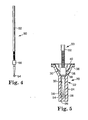
- the applicator 50 includes an elongated, generally cylindrical shaft 52 having a tip 54 at one end.
- the tip 54 includes a roughened surface to facilitate mixing of the components 42, 44.
- the tip 54 could comprise a compressible, porous material such as a sponge, or comprise a plurality of fibers or other protrusions.
- a suitable applicator 50 is the "MICROBRUSH” brand applicator from Microbrush Corporation of Orlando, Florida.
- the "MICROBRUSH” brand applicator has a tip with a plurality of relatively short, flocked fibers.
- the flocked fibers also facilitate spreading of the resulting mixed composition across an application site, such as a prepared cavity surface of a tooth.
- the applicator 50 also preferably includes structure for facilitating rupture of the sheets 38, 40.
- the structure comprises a collar 56 that extends outwardly from the shaft 52 in directions perpendicular to the longitudinal axis of the shaft 52.
- the collar 56 preferably has a tapered front end that faces the tip 54, to facilitate tearing of the sheets 38, 40 when desired.
- the protruding structure of the applicator 50 may have a shape other than the shape of the collar 56 shown in the drawings.
- the protruding structure may incorporate a series of small pins, bars or pyramid-shaped bodies that are arranged in a circle about the periphery of the shaft 52.
- the protruding structure may be in the form of a cylindrical ring or sleeve.
- the protruding structure extends outwardly from the shaft 52 a distance that is at least as great as the direction of extension of the tip 54 in reference planes perpendicular to the longitudinal axis of the shaft 52, in order to further reduce the likelihood that the tip 54 will contact the sheets 38, 40 as the tip 54 is moved past the sheets 38, 40 and out of the chamber 34.
- Fig. 5 is an exemplary illustration of a possible use of the applicator 50 in combination with the container 20, except that the components 42, 44 are not shown in Fig. 5 for purposes of clarity.
- the applicator 50 is brought into a position over the container 20 such that the tip 54 contacts the second sheet 40. As the tip 54 is pressed against the second sheet 40, the second sheet 40 ruptures and presents an aperture. Continued movement of the applicator 50 in directions toward the chamber 34 causes the tip 54 to pass through the compartment 46 and contact the first sheet 38. The tip 54 is then pressed against the first sheet 38 until it also ruptures and presents an aperature.
- the second component 44 moves into the chamber 34, where it comes into contact with the first component 42.
- the applicator 50 is moved into the chamber 34 and toward the end wall section 26.
- the user can move the shaft 52 relative to the container 20 in a series of short, reciprocating back-and-forth motions so that thorough mixing of the components 42, 44 is assured.
- the back-and-forth motions of the tip 54 in the smaller section of the chamber 34 resembles a mixing action similar to the churning of butter.
- the protrusions of the internal wall surface 32 function to facilitate mixing of the components 42, 44 as the tip 54 passes by the wall surface 32.
- the protruding structure of the tip 54 (such as the flocked fibers mentioned above) also facilitates thorough mixing of the components 42, 44.
- the components 42, 44 are directed through, in and across the protrusions which serve to enhance intermingling and thorough, uniform contact of the components 42, 44 with each other.
- the collar 56 is spaced from the outer end of the tip 54 a distance that is approximately equal or slightly less than the distance between the end wall section 26 and the junction between the lower segment 28 and the upper segment 30. Moreover, the collar 56 extends outwardly from the shaft 52 in directions generally perpendicular to the longitudinal axis of the applicator 50 a distance sufficient to prevent entry of the collar 56 into the lower cylindrical segment 28. As a result, the collar 56 serves as a stop to prevent contact of the tip 54 with the end wall section 26. By preventing contact of the tip 54 with the end wall section 26, the outer end of the tip 54 is not damaged. In addition, the mixed composition that is present on the tip 54 is not expressed away from the outer end of the tip 54 as might occur, for example, if the outer end of the outer end of the tip 54 was pressed against the end wall section 26.
- the applicator 50 is withdrawn from the chamber 34.
- the additional tearing of the sheets 38, 40 provided by passage of the collar 56 reduces the likelihood that the sides of the tip 54 will contact the sheets 38, 40 as the tip 54 is subsequently withdrawn from the container 20.
- the composition is not wiped away from the surface of the tip 54 by the sheets 38, 40, with the result that a greater quantity of the composition is available for transfer to the application site.
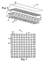
- Figs. 6 and 7 are illustrations of an exemplary set of containers 20 arranged in an array 60.
- Fig. 6 illustrates the array 60 in exploded format and as it might appear during manufacture before assembly.
- the number of containers 20 in the array 60 may vary from that shown in the drawings, and the array 60 may alternatively have containers 20 positioned in other arrangements as desired.
- the array 60 includes a unit 62, a first film 64 and a second film 66.
- the unit 62 includes a number of housings 22 that are connected together by a flat substrate 68.
- the substrate 68 and all of the housings 22 are integrally molded together as a single, unitary body.
- FIG. 7 A top view of the unit 62 alone is shown in Fig. 7 .
- the substrate 68 includes lines of weakness 70 that, in this embodiment, extend in circles overlying the outer edge of each flange 36 ( Figs. 2 and 5 ).
- the lines of weakness 70 may be provided by forming a groove or a series of grooves or perforations in the substrate 68, or by any other suitable means.
- the first film 64 and the second film 66 are co-terminus with the periphery of the substrate 68 in the illustrated embodiment.
- the first film 64 includes a number of formed bulged-shaped portions that provide the first sheet 38 described above and shown in Fig. 2 .
- the second film 66 is planar and provides the second sheets 40 as mentioned above for each of the housings 22.
- the films 64, 66 are both cut in a circular pattern directly overlying each circular line of weakness 70.
- the individual containers 20 may be detached from the array 60 as needed by grasping a housing 22 and bending the housing 22 relative to remaining housings 22 in the array 60. As the selected housing 22 is bent, the line of weakness 70 corresponding to that housing 22 fractures. In addition, the corresponding lines of weakness in the films 64, 66 overlying the selected housing 22 also rupture. The selected container 20 may then be detached from remaining containers 20 in the array 60.
- the lines of weakness (such as the lines of weakness 70) of the array 60 described above are preferably circular in shape in order to avoid sharp edges in the vicinity of the flange 36.
- the lines of weakness may have other shapes as well.
- An example of an alternative pattern of lines of weakness is a rectangular grid having lines of weakness that extend between each adjacent pair of containers 20.
- the array 60 is an advantage for the user, in that the containers 20 are kept in orderly fashion until detached by the user from remaining containers 20. Moreover, the array 60 is an advantage during manufacture, because automated dispensing apparatus having a similar, matching array of dispensing needles can be utilized to direct the components into all of the containers 20 (or at least a group of such containers 20) in simultaneous fashion. The array 60 also simplifies handling of multiple numbers of the containers 20 during manufacture, shipping and storage.
- FIG. 8 A storage and dispensing container 20a according to another embodiment of the invention is shown in Fig. 8 .
- the container 20a is essentially the same as the container 20 described above, except that the container 20a includes a section of porous material 74a that is received in a chamber 34a of the container 20a.
- Other aspects of the container 20a are the same as the aspects of the container 20 described above, and as such a detailed description of those aspects need not be repeated.
- the porous material 74a is compressible.
- a suitable porous material 74a is a sponge such as a synthetic sponge made of polyurethane.
- the porous material 74a serves to hinder unintentional leakage or drippage of liquid components from the chamber 34a in instances where the container 20a is inverted.
- the porous material 74a promotes mixing of components, especially in instances when the tip of the applicator compresses the porous material during the reciprocating mixing motion.
- a mixing and dispensing container 20b according to another embodiment of the invention is illustrated in Fig. 9 .
- the container 20b includes a housing 22b having a somewhat funnel-shaped overall configuration with an inner chamber.
- the container 20b includes two sheets (not shown) similar to the sheets 38, 40 that together A define a compartment similar to the compartment 46.
- a component is received in the compartment as well as in the chamber, in a manner similar to reception of the components 42, 44 in the compartment 46 and the chamber 34.
- the container 20b includes an articulated holder 76b.
- the holder 76b includes an outer funnel-shaped end 78b that is connected by a stem 79b to a socket 84b.
- the socket 84b receives a ball-shaped segment 82b and includes a plurality of fingers that extend part of the way across the surface of the ball-shaped segment 82b.
- the segment 82b and the socket 84b together comprise a ball-and-socket joint which provides articulated movement between the holder 76b and the housing 22b.
- the ball-shaped segment 82b is connected by a stem 80b to the housing 22b.
- the fingers of the socket 84b are spaced sufficiently far apart from each other so that the stem 80b can be received between an adjacent pair of the fingers of the socket 84b when the holder 76b is oriented 90 degrees relative to the longitudinal axis of the stem 80b.
- Fig. 9 an example of such a 90 degree orientation is shown by the dashed lines of the housing 22b.
- the container 20b also includes a disk-shaped support 86b that is adjacent the holder 76b.
- the support 86b is spaced from the end 78b a distance sufficient to receive the users fingers in the space between the support 86b and the end 78b.
- the support 86b enhances the user's grip on the container 20b, and as a result less effort is required to keep the container 20b in place between the user's fingers when desired.
- the holder 76b and the socket 84b are made of a plastic material than can withstand autoclaving, such as polyetheretherketone ("PEEK”) or polysulfone ("PSU").
- PEEK polyetheretherketone
- PSU polysulfone
- the fingers of the socket 84b are sufficiently resilient so that the ball-shaped segment 82b is received in the socket 84b in snap-fit relation, using just enough pressure to deflect the fingers outwardly in order to receive the segment 82b.
- the fingers provide sufficient frictional resistance so that the orientation of the holder 76b relative to the housing 22b remains fixed during ordinary use once adjustment has been made, if necessary, to move the housing 22b to a desired position.
- the housing 22b may be made of polypropylene.
- a container 20c includes a housing 22c with a lower, cylindrical segment 28c and an upper, funnel shaped segment 30c.
- the housing 22c includes an annular shoulder 88c that is located between the lower segment 28c and the upper segment 30c.
- a first sheet (not shown) is affixed to the shoulder 88c, and a second sheet 40c extends over the first sheet.
- a compartment similar to the compartment 46 described above, is located between the first sheet and the second sheet 40c and receives a quantity of a second component.
- a quantity of a first component is received in a lower, cylindrical section of the chamber 34c that extends in the lower segment 28c.
- the container 20c may provide an advantage in certain instances in order to help avoid any spilling or splashing of the second component when the first and second sheets are ruptured. Additionally, the upper, funnel-shaped segment 30c helps to guide the applicator into a proper position for puncturing the sheets.
- a container 20d according to another embodiment of the invention is illustrated in Fig. 11 .
- the container 20d includes a housing 22d having a lower segment 28d and an upper segment 30d.
- the lower segment 28d surrounds an internal chamber 34d having a semi-spherical bottom wall.
- An annular shoulder 88d extends in a plane that is perpendicular to a central axis of the container 20d.
- a first sheet 38d is affixed to the shoulder 88d.
- a second sheet 40d is affixed to an outer end of the housing 22d.
- both of the sheets 38d, 40d are affixed to the housing by an adhesive (such as a heat-seal coating), by ultrasonic bonding, by a pressure-sensitive adhesive or by any other suitable means.
- the first sheet 38d is spaced from the second sheet 40d to present a compartment 46d.
- the compartment 46d receives a quantity of a second component (not shown).
- a first component is received in the chamber 34d below the first sheet 38d.
- Other aspects of the container 20d are similar to the container 20 described above.
- the container 20d may also be modified to present additional compartments if desired.
- the container 20d may include an additional internal shoulder and an additional film, so that three components may be held in isolation from each other until the films are ruptured to mix the components together.
- the lower end wall may be replaced by a film in order to facilitate manufacturing.
Landscapes
- Health & Medical Sciences (AREA)
- Oral & Maxillofacial Surgery (AREA)
- Dentistry (AREA)
- Epidemiology (AREA)
- Life Sciences & Earth Sciences (AREA)
- Animal Behavior & Ethology (AREA)
- General Health & Medical Sciences (AREA)
- Public Health (AREA)
- Veterinary Medicine (AREA)
- Details Of Rigid Or Semi-Rigid Containers (AREA)
- Medical Preparation Storing Or Oral Administration Devices (AREA)
- Containers And Packaging Bodies Having A Special Means To Remove Contents (AREA)
- Dental Tools And Instruments Or Auxiliary Dental Instruments (AREA)
- Package Specialized In Special Use (AREA)
Priority Applications (1)
| Application Number | Priority Date | Filing Date | Title |
|---|---|---|---|
| EP09179086A EP2177176A1 (en) | 2001-04-20 | 2002-01-30 | Container for multiple-component compositions |
Applications Claiming Priority (3)
| Application Number | Priority Date | Filing Date | Title |
|---|---|---|---|
| US838875 | 2001-04-20 | ||
| US09/838,875 US6419414B1 (en) | 2001-04-20 | 2001-04-20 | Container for multiple-component compositions |
| PCT/US2002/002720 WO2002085240A2 (en) | 2001-04-20 | 2002-01-30 | Container for multiple-component compositions |
Related Child Applications (1)
| Application Number | Title | Priority Date | Filing Date |
|---|---|---|---|
| EP09179086.5 Division-Into | 2009-12-14 |
Publications (2)
| Publication Number | Publication Date |
|---|---|
| EP1424953A2 EP1424953A2 (en) | 2004-06-09 |
| EP1424953B1 true EP1424953B1 (en) | 2010-09-22 |
Family
ID=25278281
Family Applications (2)
| Application Number | Title | Priority Date | Filing Date |
|---|---|---|---|
| EP02702109A Expired - Lifetime EP1424953B1 (en) | 2001-04-20 | 2002-01-30 | Container for multiple-component compositions |
| EP09179086A Withdrawn EP2177176A1 (en) | 2001-04-20 | 2002-01-30 | Container for multiple-component compositions |
Family Applications After (1)
| Application Number | Title | Priority Date | Filing Date |
|---|---|---|---|
| EP09179086A Withdrawn EP2177176A1 (en) | 2001-04-20 | 2002-01-30 | Container for multiple-component compositions |
Country Status (6)
| Country | Link |
|---|---|
| US (1) | US6419414B1 (enExample) |
| EP (2) | EP1424953B1 (enExample) |
| JP (1) | JP4271945B2 (enExample) |
| AT (1) | ATE481940T1 (enExample) |
| DE (1) | DE60237776D1 (enExample) |
| WO (1) | WO2002085240A2 (enExample) |
Families Citing this family (16)
| Publication number | Priority date | Publication date | Assignee | Title |
|---|---|---|---|---|
| US7112062B2 (en) * | 2003-12-05 | 2006-09-26 | 3M Innovative Properties Co. | Dental material storage and delivery system and method |
| US7131784B2 (en) * | 2004-03-11 | 2006-11-07 | 3M Innovative Properties Company | Unit dose delivery system |
| US7581899B2 (en) * | 2004-11-30 | 2009-09-01 | James Alexander Corporation | Dispenser and process |
| US20050111900A1 (en) * | 2004-11-30 | 2005-05-26 | Francesca Fazzolari | Ampoule and method of use |
| DE102006015238A1 (de) * | 2006-03-30 | 2007-10-04 | S&C Polymer Silicon- und Composite-Spezialitäten GmbH | Einwegverpackungssystem zur Lagerung und Ausbringung von Mehrkomponentenmaterialien |
| US20070246381A1 (en) * | 2006-04-21 | 2007-10-25 | Pond Gary J | Telescoping ampoule device |
| US7976234B2 (en) | 2006-04-28 | 2011-07-12 | James Alexander Corporation | Multi-chambered dispenser and process |
| US8403178B2 (en) | 2007-12-18 | 2013-03-26 | James Alexander Corporation | Container assembly |
| US8100294B2 (en) | 2007-12-18 | 2012-01-24 | James Alexander Corporation | Container assembly |
| US8910830B2 (en) | 2007-12-18 | 2014-12-16 | James Alexander Corporation | Container assembly |
| ATE548285T1 (de) | 2008-01-29 | 2012-03-15 | James Alexander Corp | Spender |
| WO2010039106A1 (en) * | 2008-10-03 | 2010-04-08 | Garry Tsaur | Multi-chamber container |
| EP2202042B1 (en) * | 2008-12-24 | 2013-02-20 | Albéa Services | A container and applicator arrangement for a cosmetic product, and associated method of manufacture |
| US8317721B2 (en) * | 2009-10-15 | 2012-11-27 | Patrick Win | Reuseable skin testing device |
| US20130164706A1 (en) * | 2011-12-23 | 2013-06-27 | Gsn Products, Inc. | Adjustable suction tips for dental and medical uses |
| US20210298450A1 (en) * | 2020-03-27 | 2021-09-30 | APR Beauty Group, Inc. | Cosmetic applicator |
Family Cites Families (32)
| Publication number | Priority date | Publication date | Assignee | Title |
|---|---|---|---|---|
| US2612163A (en) | 1950-10-09 | 1952-09-30 | Wilson Y Norman | Container for hypodermic preparations |
| US2624011A (en) | 1951-03-27 | 1952-12-30 | Kurt G Stern | Self-developing pocket radiation dosimeter |
| US2862616A (en) | 1958-03-17 | 1958-12-02 | Lancaster Chemical Corp | Method of packaging epoxy resins |
| US3359361A (en) | 1966-03-11 | 1967-12-19 | Hysol Corp | Insulating device for wire and cable ends |
| US3340873A (en) | 1966-05-13 | 1967-09-12 | Solowey Ida | Compartmented medical container having a rupturable diaphragm between compartments |
| DE1773584A1 (de) | 1967-06-13 | 1973-01-04 | Xerox Corp | Reaktionsbehaelter |
| US3613697A (en) | 1970-06-09 | 1971-10-19 | Maurice Andrews | Device to be used when applying a cosmetic |
| US3713780A (en) * | 1971-02-01 | 1973-01-30 | Becton Dickinson Co | Apparatus for chemical testing |
| US3776220A (en) * | 1972-05-09 | 1973-12-04 | F Monaghan | Diagnostic swab with stored culture medium |
| US4152269A (en) | 1977-02-01 | 1979-05-01 | Warner-Lambert Company | Collection and separation device |
| US4150950A (en) * | 1977-09-28 | 1979-04-24 | Corning Glass Works | Transport system for clinical specimens |
| US4196167A (en) * | 1978-12-26 | 1980-04-01 | California Medical Developments, Inc. | Drug detection device |
| DE3303838A1 (de) | 1983-02-04 | 1984-08-09 | Mühlbauer, Ernst, Dipl.-Kaufm., 2000 Hamburg | Mehrkomponentenkapsel |
| US4828419A (en) | 1986-10-07 | 1989-05-09 | Cosmolab, Inc. | Cake cosmetic applicator |
| US4845923A (en) * | 1987-08-06 | 1989-07-11 | Donovan Dennis M | Contaminated sharp object disposal method |
| US4912048A (en) * | 1987-12-21 | 1990-03-27 | Difco Laboratories | Fluted culture vessel |
| US4952204A (en) | 1988-08-10 | 1990-08-28 | Gam-Med Packaging Corporation | Dry handle swab assembly and unit |
| US5514120A (en) | 1991-12-18 | 1996-05-07 | Minnesota Mining And Manufacturing Company | Liquid management member for absorbent articles |
| US5322165A (en) * | 1993-02-16 | 1994-06-21 | University Of Florida | Sharp instrument encasement system |
| SE502003C2 (sv) | 1993-11-08 | 1995-07-10 | Matts Folkoe | Salivsug innefattande ett antal styva sektionselement |
| GB9405590D0 (en) * | 1994-03-22 | 1994-05-11 | Celsis Ltd | Assay device |
| US5660273A (en) | 1994-07-13 | 1997-08-26 | Centrix, Inc. | Single patient dose medicament dispenser with applicator |
| US5827675A (en) * | 1995-07-12 | 1998-10-27 | Charm Sciences, Inc. | Test apparatus, system and method for the detection of test samples |
| US5735437A (en) | 1996-01-22 | 1998-04-07 | Minnesota Mining And Manufacturing | Lockable, hand-held dispenser and mixing tray for dispensing small quantities of material |
| US5780305A (en) | 1996-10-15 | 1998-07-14 | Chisum; William J. | Method for using forensic sampler |
| US5860806A (en) | 1996-11-29 | 1999-01-19 | The Kerr Corporation | Single dose dental adhesive delivery system and method and adhesive therefor |
| US5989229A (en) | 1997-05-28 | 1999-11-23 | Becton, Dickinson And Company | Needle cover assembly having self-contained drug applicator |
| US6431695B1 (en) | 1998-06-18 | 2002-08-13 | 3M Innovative Properties Company | Microstructure liquid dispenser |
| DE29714246U1 (de) | 1997-08-08 | 1998-12-10 | THERA Patent GmbH & Co. KG Gesellschaft für industrielle Schutzrechte, 82229 Seefeld | Vorrichtung zum Lagern und Auftragen einer fließfähigen Substanz |
| AU3680100A (en) * | 1999-04-22 | 2000-11-10 | Kikkoman Corporation | Instrument for testing specimen and instrument for wipe test |
| US6095813A (en) | 1999-06-14 | 2000-08-01 | 3M Innovative Properties Company | Method for applying a dental composition to tooth structure |
| EP1153579B1 (de) * | 2000-05-10 | 2007-11-07 | VOCO GmbH | Vorrichtung zum Lagern und Applizieren ein- oder mehrkomponentiger fliessfähiger Dentalmaterialien |
-
2001
- 2001-04-20 US US09/838,875 patent/US6419414B1/en not_active Expired - Lifetime
-
2002
- 2002-01-30 EP EP02702109A patent/EP1424953B1/en not_active Expired - Lifetime
- 2002-01-30 JP JP2002582821A patent/JP4271945B2/ja not_active Expired - Fee Related
- 2002-01-30 AT AT02702109T patent/ATE481940T1/de not_active IP Right Cessation
- 2002-01-30 DE DE60237776T patent/DE60237776D1/de not_active Expired - Lifetime
- 2002-01-30 WO PCT/US2002/002720 patent/WO2002085240A2/en not_active Ceased
- 2002-01-30 EP EP09179086A patent/EP2177176A1/en not_active Withdrawn
Also Published As
| Publication number | Publication date |
|---|---|
| JP2004528094A (ja) | 2004-09-16 |
| JP4271945B2 (ja) | 2009-06-03 |
| WO2002085240A3 (en) | 2004-03-11 |
| WO2002085240A2 (en) | 2002-10-31 |
| ATE481940T1 (de) | 2010-10-15 |
| EP2177176A1 (en) | 2010-04-21 |
| US6419414B1 (en) | 2002-07-16 |
| EP1424953A2 (en) | 2004-06-09 |
| DE60237776D1 (enExample) | 2010-11-04 |
Similar Documents
| Publication | Publication Date | Title |
|---|---|---|
| EP1424953B1 (en) | Container for multiple-component compositions | |
| US6543612B2 (en) | Container for compositions made of two or more components | |
| US7625114B2 (en) | Device having sealed breakable chambers for storing and dispensing viscous substances | |
| US6105761A (en) | Device for storing and dispensing a flowable substance | |
| US6991393B2 (en) | Liquid applicator for coloring a liquid | |
| US6758618B2 (en) | Container and applicator assembly | |
| US4972969A (en) | Assembly for storing mixing and dispensing preparations such as dental materials | |
| AU2002221818B2 (en) | Device for storing and dispensing flowable compositions | |
| JP2004515424A (ja) | 多成分組成物のためのパッケージおよび分配アクチュエータ | |
| AU2005222573B2 (en) | Unit dose delivery system for two-component composition | |
| US20220192784A1 (en) | Dental capsule | |
| EP2244956B1 (en) | Dental package | |
| US20120017412A1 (en) | Package and dispensing system | |
| EP4014921B1 (en) | Dental capsule |
Legal Events
| Date | Code | Title | Description |
|---|---|---|---|
| PUAI | Public reference made under article 153(3) epc to a published international application that has entered the european phase |
Free format text: ORIGINAL CODE: 0009012 |
|
| AK | Designated contracting states |
Kind code of ref document: A2 Designated state(s): AT BE CH CY DE DK ES FI FR GB GR IE IT LI LU MC NL PT SE TR |
|
| AX | Request for extension of the european patent |
Extension state: AL LT LV MK RO SI |
|
| 17P | Request for examination filed |
Effective date: 20031113 |
|
| 17Q | First examination report despatched |
Effective date: 20090212 |
|
| GRAP | Despatch of communication of intention to grant a patent |
Free format text: ORIGINAL CODE: EPIDOSNIGR1 |
|
| GRAS | Grant fee paid |
Free format text: ORIGINAL CODE: EPIDOSNIGR3 |
|
| GRAA | (expected) grant |
Free format text: ORIGINAL CODE: 0009210 |
|
| AK | Designated contracting states |
Kind code of ref document: B1 Designated state(s): AT BE CH CY DE DK ES FI FR GB GR IE IT LI LU MC NL PT SE TR |
|
| REG | Reference to a national code |
Ref country code: GB Ref legal event code: FG4D |
|
| REG | Reference to a national code |
Ref country code: CH Ref legal event code: EP |
|
| REG | Reference to a national code |
Ref country code: IE Ref legal event code: FG4D |
|
| REF | Corresponds to: |
Ref document number: 60237776 Country of ref document: DE Date of ref document: 20101104 Kind code of ref document: P |
|
| PG25 | Lapsed in a contracting state [announced via postgrant information from national office to epo] |
Ref country code: FI Free format text: LAPSE BECAUSE OF FAILURE TO SUBMIT A TRANSLATION OF THE DESCRIPTION OR TO PAY THE FEE WITHIN THE PRESCRIBED TIME-LIMIT Effective date: 20100922 Ref country code: AT Free format text: LAPSE BECAUSE OF FAILURE TO SUBMIT A TRANSLATION OF THE DESCRIPTION OR TO PAY THE FEE WITHIN THE PRESCRIBED TIME-LIMIT Effective date: 20100922 |
|
| REG | Reference to a national code |
Ref country code: NL Ref legal event code: VDEP Effective date: 20100922 |
|
| PG25 | Lapsed in a contracting state [announced via postgrant information from national office to epo] |
Ref country code: SE Free format text: LAPSE BECAUSE OF FAILURE TO SUBMIT A TRANSLATION OF THE DESCRIPTION OR TO PAY THE FEE WITHIN THE PRESCRIBED TIME-LIMIT Effective date: 20100922 Ref country code: GR Free format text: LAPSE BECAUSE OF FAILURE TO SUBMIT A TRANSLATION OF THE DESCRIPTION OR TO PAY THE FEE WITHIN THE PRESCRIBED TIME-LIMIT Effective date: 20101223 |
|
| PG25 | Lapsed in a contracting state [announced via postgrant information from national office to epo] |
Ref country code: NL Free format text: LAPSE BECAUSE OF FAILURE TO SUBMIT A TRANSLATION OF THE DESCRIPTION OR TO PAY THE FEE WITHIN THE PRESCRIBED TIME-LIMIT Effective date: 20100922 Ref country code: PT Free format text: LAPSE BECAUSE OF FAILURE TO SUBMIT A TRANSLATION OF THE DESCRIPTION OR TO PAY THE FEE WITHIN THE PRESCRIBED TIME-LIMIT Effective date: 20110124 Ref country code: IT Free format text: LAPSE BECAUSE OF FAILURE TO SUBMIT A TRANSLATION OF THE DESCRIPTION OR TO PAY THE FEE WITHIN THE PRESCRIBED TIME-LIMIT Effective date: 20100922 |
|
| PG25 | Lapsed in a contracting state [announced via postgrant information from national office to epo] |
Ref country code: BE Free format text: LAPSE BECAUSE OF FAILURE TO SUBMIT A TRANSLATION OF THE DESCRIPTION OR TO PAY THE FEE WITHIN THE PRESCRIBED TIME-LIMIT Effective date: 20100922 |
|
| PG25 | Lapsed in a contracting state [announced via postgrant information from national office to epo] |
Ref country code: ES Free format text: LAPSE BECAUSE OF FAILURE TO SUBMIT A TRANSLATION OF THE DESCRIPTION OR TO PAY THE FEE WITHIN THE PRESCRIBED TIME-LIMIT Effective date: 20110102 |
|
| PLBE | No opposition filed within time limit |
Free format text: ORIGINAL CODE: 0009261 |
|
| STAA | Information on the status of an ep patent application or granted ep patent |
Free format text: STATUS: NO OPPOSITION FILED WITHIN TIME LIMIT |
|
| 26N | No opposition filed |
Effective date: 20110623 |
|
| PG25 | Lapsed in a contracting state [announced via postgrant information from national office to epo] |
Ref country code: DK Free format text: LAPSE BECAUSE OF FAILURE TO SUBMIT A TRANSLATION OF THE DESCRIPTION OR TO PAY THE FEE WITHIN THE PRESCRIBED TIME-LIMIT Effective date: 20100922 Ref country code: MC Free format text: LAPSE BECAUSE OF NON-PAYMENT OF DUE FEES Effective date: 20110131 |
|
| GBPC | Gb: european patent ceased through non-payment of renewal fee |
Effective date: 20110130 |
|
| REG | Reference to a national code |
Ref country code: FR Ref legal event code: ST Effective date: 20110930 |
|
| REG | Reference to a national code |
Ref country code: DE Ref legal event code: R097 Ref document number: 60237776 Country of ref document: DE Effective date: 20110623 |
|
| REG | Reference to a national code |
Ref country code: IE Ref legal event code: MM4A |
|
| PG25 | Lapsed in a contracting state [announced via postgrant information from national office to epo] |
Ref country code: FR Free format text: LAPSE BECAUSE OF NON-PAYMENT OF DUE FEES Effective date: 20110131 |
|
| PG25 | Lapsed in a contracting state [announced via postgrant information from national office to epo] |
Ref country code: GB Free format text: LAPSE BECAUSE OF NON-PAYMENT OF DUE FEES Effective date: 20110130 |
|
| PG25 | Lapsed in a contracting state [announced via postgrant information from national office to epo] |
Ref country code: IE Free format text: LAPSE BECAUSE OF NON-PAYMENT OF DUE FEES Effective date: 20110130 |
|
| PG25 | Lapsed in a contracting state [announced via postgrant information from national office to epo] |
Ref country code: CY Free format text: LAPSE BECAUSE OF FAILURE TO SUBMIT A TRANSLATION OF THE DESCRIPTION OR TO PAY THE FEE WITHIN THE PRESCRIBED TIME-LIMIT Effective date: 20100922 Ref country code: LU Free format text: LAPSE BECAUSE OF NON-PAYMENT OF DUE FEES Effective date: 20110130 |
|
| PG25 | Lapsed in a contracting state [announced via postgrant information from national office to epo] |
Ref country code: TR Free format text: LAPSE BECAUSE OF FAILURE TO SUBMIT A TRANSLATION OF THE DESCRIPTION OR TO PAY THE FEE WITHIN THE PRESCRIBED TIME-LIMIT Effective date: 20100922 |
|
| PGFP | Annual fee paid to national office [announced via postgrant information from national office to epo] |
Ref country code: DE Payment date: 20150127 Year of fee payment: 14 |
|
| PGFP | Annual fee paid to national office [announced via postgrant information from national office to epo] |
Ref country code: CH Payment date: 20160111 Year of fee payment: 15 |
|
| REG | Reference to a national code |
Ref country code: DE Ref legal event code: R119 Ref document number: 60237776 Country of ref document: DE |
|
| PG25 | Lapsed in a contracting state [announced via postgrant information from national office to epo] |
Ref country code: DE Free format text: LAPSE BECAUSE OF NON-PAYMENT OF DUE FEES Effective date: 20160802 |
|
| REG | Reference to a national code |
Ref country code: CH Ref legal event code: PL |
|
| PG25 | Lapsed in a contracting state [announced via postgrant information from national office to epo] |
Ref country code: LI Free format text: LAPSE BECAUSE OF NON-PAYMENT OF DUE FEES Effective date: 20170131 Ref country code: CH Free format text: LAPSE BECAUSE OF NON-PAYMENT OF DUE FEES Effective date: 20170131 |