EP1424937B1 - Medizinisches implantatsystem - Google Patents
Medizinisches implantatsystem Download PDFInfo
- Publication number
- EP1424937B1 EP1424937B1 EP02791457A EP02791457A EP1424937B1 EP 1424937 B1 EP1424937 B1 EP 1424937B1 EP 02791457 A EP02791457 A EP 02791457A EP 02791457 A EP02791457 A EP 02791457A EP 1424937 B1 EP1424937 B1 EP 1424937B1
- Authority
- EP
- European Patent Office
- Prior art keywords
- implant system
- implant
- radiation
- sensor
- measuring device
- Prior art date
- Legal status (The legal status is an assumption and is not a legal conclusion. Google has not performed a legal analysis and makes no representation as to the accuracy of the status listed.)
- Expired - Lifetime
Links
Images


Classifications
-
- A—HUMAN NECESSITIES
- A61—MEDICAL OR VETERINARY SCIENCE; HYGIENE
- A61B—DIAGNOSIS; SURGERY; IDENTIFICATION
- A61B17/00—Surgical instruments, devices or methods
- A61B17/56—Surgical instruments or methods for treatment of bones or joints; Devices specially adapted therefor
- A61B17/58—Surgical instruments or methods for treatment of bones or joints; Devices specially adapted therefor for osteosynthesis, e.g. bone plates, screws or setting implements
- A61B17/68—Internal fixation devices, including fasteners and spinal fixators, even if a part thereof projects from the skin
- A61B17/72—Intramedullary devices, e.g. pins or nails
- A61B17/7208—Flexible pins, e.g. ENDER pins
-
- A—HUMAN NECESSITIES
- A61—MEDICAL OR VETERINARY SCIENCE; HYGIENE
- A61B—DIAGNOSIS; SURGERY; IDENTIFICATION
- A61B17/00—Surgical instruments, devices or methods
- A61B17/56—Surgical instruments or methods for treatment of bones or joints; Devices specially adapted therefor
- A61B17/58—Surgical instruments or methods for treatment of bones or joints; Devices specially adapted therefor for osteosynthesis, e.g. bone plates, screws or setting implements
- A61B17/68—Internal fixation devices, including fasteners and spinal fixators, even if a part thereof projects from the skin
- A61B17/80—Cortical plates, i.e. bone plates; Instruments for holding or positioning cortical plates, or for compressing bones attached to cortical plates
- A61B17/8085—Cortical plates, i.e. bone plates; Instruments for holding or positioning cortical plates, or for compressing bones attached to cortical plates with pliable or malleable elements or having a mesh-like structure, e.g. small strips
-
- A—HUMAN NECESSITIES
- A61—MEDICAL OR VETERINARY SCIENCE; HYGIENE
- A61B—DIAGNOSIS; SURGERY; IDENTIFICATION
- A61B5/00—Measuring for diagnostic purposes; Identification of persons
- A61B5/0002—Remote monitoring of patients using telemetry, e.g. transmission of vital signals via a communication network
- A61B5/0031—Implanted circuitry
-
- A—HUMAN NECESSITIES
- A61—MEDICAL OR VETERINARY SCIENCE; HYGIENE
- A61B—DIAGNOSIS; SURGERY; IDENTIFICATION
- A61B5/00—Measuring for diagnostic purposes; Identification of persons
- A61B5/07—Endoradiosondes
-
- G—PHYSICS
- G01—MEASURING; TESTING
- G01N—INVESTIGATING OR ANALYSING MATERIALS BY DETERMINING THEIR CHEMICAL OR PHYSICAL PROPERTIES
- G01N21/00—Investigating or analysing materials by the use of optical means, i.e. using sub-millimetre waves, infrared, visible or ultraviolet light
- G01N21/75—Systems in which material is subjected to a chemical reaction, the progress or the result of the reaction being investigated
- G01N21/77—Systems in which material is subjected to a chemical reaction, the progress or the result of the reaction being investigated by observing the effect on a chemical indicator
- G01N21/7703—Systems in which material is subjected to a chemical reaction, the progress or the result of the reaction being investigated by observing the effect on a chemical indicator using reagent-clad optical fibres or optical waveguides
-
- A—HUMAN NECESSITIES
- A61—MEDICAL OR VETERINARY SCIENCE; HYGIENE
- A61B—DIAGNOSIS; SURGERY; IDENTIFICATION
- A61B17/00—Surgical instruments, devices or methods
- A61B17/56—Surgical instruments or methods for treatment of bones or joints; Devices specially adapted therefor
-
- A—HUMAN NECESSITIES
- A61—MEDICAL OR VETERINARY SCIENCE; HYGIENE
- A61B—DIAGNOSIS; SURGERY; IDENTIFICATION
- A61B17/00—Surgical instruments, devices or methods
- A61B17/56—Surgical instruments or methods for treatment of bones or joints; Devices specially adapted therefor
- A61B17/58—Surgical instruments or methods for treatment of bones or joints; Devices specially adapted therefor for osteosynthesis, e.g. bone plates, screws or setting implements
-
- A—HUMAN NECESSITIES
- A61—MEDICAL OR VETERINARY SCIENCE; HYGIENE
- A61B—DIAGNOSIS; SURGERY; IDENTIFICATION
- A61B17/00—Surgical instruments, devices or methods
- A61B17/56—Surgical instruments or methods for treatment of bones or joints; Devices specially adapted therefor
- A61B17/58—Surgical instruments or methods for treatment of bones or joints; Devices specially adapted therefor for osteosynthesis, e.g. bone plates, screws or setting implements
- A61B17/68—Internal fixation devices, including fasteners and spinal fixators, even if a part thereof projects from the skin
- A61B17/70—Spinal positioners or stabilisers, e.g. stabilisers comprising fluid filler in an implant
-
- A—HUMAN NECESSITIES
- A61—MEDICAL OR VETERINARY SCIENCE; HYGIENE
- A61B—DIAGNOSIS; SURGERY; IDENTIFICATION
- A61B17/00—Surgical instruments, devices or methods
- A61B17/56—Surgical instruments or methods for treatment of bones or joints; Devices specially adapted therefor
- A61B17/58—Surgical instruments or methods for treatment of bones or joints; Devices specially adapted therefor for osteosynthesis, e.g. bone plates, screws or setting implements
- A61B17/68—Internal fixation devices, including fasteners and spinal fixators, even if a part thereof projects from the skin
- A61B17/80—Cortical plates, i.e. bone plates; Instruments for holding or positioning cortical plates, or for compressing bones attached to cortical plates
-
- A—HUMAN NECESSITIES
- A61—MEDICAL OR VETERINARY SCIENCE; HYGIENE
- A61B—DIAGNOSIS; SURGERY; IDENTIFICATION
- A61B17/00—Surgical instruments, devices or methods
- A61B2017/00004—(bio)absorbable, (bio)resorbable or resorptive
-
- A—HUMAN NECESSITIES
- A61—MEDICAL OR VETERINARY SCIENCE; HYGIENE
- A61B—DIAGNOSIS; SURGERY; IDENTIFICATION
- A61B90/00—Instruments, implements or accessories specially adapted for surgery or diagnosis and not covered by any of the groups A61B1/00 - A61B50/00, e.g. for luxation treatment or for protecting wound edges
- A61B90/06—Measuring instruments not otherwise provided for
- A61B2090/061—Measuring instruments not otherwise provided for for measuring dimensions, e.g. length
-
- A—HUMAN NECESSITIES
- A61—MEDICAL OR VETERINARY SCIENCE; HYGIENE
- A61B—DIAGNOSIS; SURGERY; IDENTIFICATION
- A61B90/00—Instruments, implements or accessories specially adapted for surgery or diagnosis and not covered by any of the groups A61B1/00 - A61B50/00, e.g. for luxation treatment or for protecting wound edges
- A61B90/06—Measuring instruments not otherwise provided for
- A61B2090/064—Measuring instruments not otherwise provided for for measuring force, pressure or mechanical tension
-
- A—HUMAN NECESSITIES
- A61—MEDICAL OR VETERINARY SCIENCE; HYGIENE
- A61B—DIAGNOSIS; SURGERY; IDENTIFICATION
- A61B5/00—Measuring for diagnostic purposes; Identification of persons
- A61B5/45—For evaluating or diagnosing the musculoskeletal system or teeth
- A61B5/4504—Bones
-
- A—HUMAN NECESSITIES
- A61—MEDICAL OR VETERINARY SCIENCE; HYGIENE
- A61B—DIAGNOSIS; SURGERY; IDENTIFICATION
- A61B90/00—Instruments, implements or accessories specially adapted for surgery or diagnosis and not covered by any of the groups A61B1/00 - A61B50/00, e.g. for luxation treatment or for protecting wound edges
- A61B90/06—Measuring instruments not otherwise provided for
-
- A—HUMAN NECESSITIES
- A61—MEDICAL OR VETERINARY SCIENCE; HYGIENE
- A61F—FILTERS IMPLANTABLE INTO BLOOD VESSELS; PROSTHESES; DEVICES PROVIDING PATENCY TO, OR PREVENTING COLLAPSING OF, TUBULAR STRUCTURES OF THE BODY, e.g. STENTS; ORTHOPAEDIC, NURSING OR CONTRACEPTIVE DEVICES; FOMENTATION; TREATMENT OR PROTECTION OF EYES OR EARS; BANDAGES, DRESSINGS OR ABSORBENT PADS; FIRST-AID KITS
- A61F2/00—Filters implantable into blood vessels; Prostheses, i.e. artificial substitutes or replacements for parts of the body; Appliances for connecting them with the body; Devices providing patency to, or preventing collapsing of, tubular structures of the body, e.g. stents
- A61F2/02—Prostheses implantable into the body
- A61F2/30—Joints
- A61F2/3094—Designing or manufacturing processes
- A61F2/30965—Reinforcing the prosthesis by embedding particles or fibres during moulding or dipping
-
- A—HUMAN NECESSITIES
- A61—MEDICAL OR VETERINARY SCIENCE; HYGIENE
- A61F—FILTERS IMPLANTABLE INTO BLOOD VESSELS; PROSTHESES; DEVICES PROVIDING PATENCY TO, OR PREVENTING COLLAPSING OF, TUBULAR STRUCTURES OF THE BODY, e.g. STENTS; ORTHOPAEDIC, NURSING OR CONTRACEPTIVE DEVICES; FOMENTATION; TREATMENT OR PROTECTION OF EYES OR EARS; BANDAGES, DRESSINGS OR ABSORBENT PADS; FIRST-AID KITS
- A61F2/00—Filters implantable into blood vessels; Prostheses, i.e. artificial substitutes or replacements for parts of the body; Appliances for connecting them with the body; Devices providing patency to, or preventing collapsing of, tubular structures of the body, e.g. stents
- A61F2/02—Prostheses implantable into the body
- A61F2/30—Joints
- A61F2/46—Special tools for implanting artificial joints
- A61F2/4657—Measuring instruments used for implanting artificial joints
-
- A—HUMAN NECESSITIES
- A61—MEDICAL OR VETERINARY SCIENCE; HYGIENE
- A61F—FILTERS IMPLANTABLE INTO BLOOD VESSELS; PROSTHESES; DEVICES PROVIDING PATENCY TO, OR PREVENTING COLLAPSING OF, TUBULAR STRUCTURES OF THE BODY, e.g. STENTS; ORTHOPAEDIC, NURSING OR CONTRACEPTIVE DEVICES; FOMENTATION; TREATMENT OR PROTECTION OF EYES OR EARS; BANDAGES, DRESSINGS OR ABSORBENT PADS; FIRST-AID KITS
- A61F2/00—Filters implantable into blood vessels; Prostheses, i.e. artificial substitutes or replacements for parts of the body; Appliances for connecting them with the body; Devices providing patency to, or preventing collapsing of, tubular structures of the body, e.g. stents
- A61F2/02—Prostheses implantable into the body
- A61F2/30—Joints
- A61F2002/30001—Additional features of subject-matter classified in A61F2/28, A61F2/30 and subgroups thereof
- A61F2002/30667—Features concerning an interaction with the environment or a particular use of the prosthesis
- A61F2002/30668—Means for transferring electromagnetic energy to implants
-
- A—HUMAN NECESSITIES
- A61—MEDICAL OR VETERINARY SCIENCE; HYGIENE
- A61F—FILTERS IMPLANTABLE INTO BLOOD VESSELS; PROSTHESES; DEVICES PROVIDING PATENCY TO, OR PREVENTING COLLAPSING OF, TUBULAR STRUCTURES OF THE BODY, e.g. STENTS; ORTHOPAEDIC, NURSING OR CONTRACEPTIVE DEVICES; FOMENTATION; TREATMENT OR PROTECTION OF EYES OR EARS; BANDAGES, DRESSINGS OR ABSORBENT PADS; FIRST-AID KITS
- A61F2250/00—Special features of prostheses classified in groups A61F2/00 - A61F2/26 or A61F2/82 or A61F9/00 or A61F11/00 or subgroups thereof
- A61F2250/0001—Means for transferring electromagnetic energy to implants
Definitions
- the invention relates to a medical implant system with a Implant made of a composite material in which glass fibers are embedded are, at least one embedded in the implant the sensor element comprising glass fibers with a measuring device is connected, which is a physical property of the sensor element or its environment or its change.
- Medical implants for example bone plates, intramedullary nails, Endoprostheses, osteosynthesis systems for the spine, etc.
- implants that consist of a composite material, in which glass fibers are embedded for reinforcement, in particular medical implants of this type consist of sterilizable, selected ones Plastics such as polyether ether ketone, polyamides etc.
- these implants When these implants are inserted into the body, they are different Exposed to influences, for example different Strains and stresses, temperature developments or chemical Environments. It would be of interest to the treating type to experience these different parameters as they provide information about the healing process or about any problems that may arise.
- the subject of the application lies based on the task of a generic medical implant system to improve so that information about physical Preserve properties in and around the implant can.
- This task is the beginning of a medical implant described type according to the invention solved in that the glass fibers in the form of a woven fabric, a knitted fabric or a fleece as a mechanical Reinforcement are embedded in the composite material.
- the glass fibers therefore form a network that is integrated into the composite material is embedded and thereby reinforced.
- Glass fibers are in various forms as a material for reinforcement known (DE 39 14 164 C1), but the glass fibers serve exclusively as reinforcement material. As part of the present Invention, however, are the glass fibers at the same time as reinforcement and used as a sensor element, and this is from the known State of the art was not obvious.
- glass fiber all fibrous, in the Composite embeddable substances that are capable of electromagnetic radiation must be conducted and transmitted, preferably these fibers are made of quartz glass, but they can also other substances are used, for example fibers Plastic, so-called plastic optical fibers (POF).
- fibers Plastic so-called plastic optical fibers (POF).
- the glass fibers can concentrated in certain areas of the implant or over the entire extent of the implant should be distributed.
- the measuring device is preferably designed so that it is electromagnetic Radiation feeds into the sensor element and from the Type of continuous and / or reflected radiation physical Properties of the sensor element or determined by its environment.
- the glass fiber of the sensor element is according to a preferred embodiment provided with a radiation reflecting coating.
- the sensor element is present essentially from the glass fiber forming a sensor fiber. In this embodiment, it is in the composite material embedded fiber optic at the same time sensor and transmission element for electromagnetic radiation.
- the glass fiber acts as a sensor fiber
- the glass fiber acts as a sensor fiber
- at least one acting as a Bragg grating in the sensor fiber Area incorporated.
- the periodic Changes in the refractive index in the longitudinal direction of the sensor fiber has radiation is reflected, which is superimposed on reflection and only for very specific wavelengths in the reverse direction strengthened.
- This wavelength depends on the periodicity of the Bragg grating area and changes with this periodicity. Every change in length the sensor fiber or any change in the periodicity of the Bragg-lattice, which occurs due to external influences, can occur can be determined in the form of a wavelength shift.
- the sensor fiber one by the fed electromagnetic Radiation to fluorescence-excited substance is embedded, their fluorescent properties under the influence of the environment experienced changes outside the sensor fiber.
- These changes can be mechanical changes, but in particular the Fluorescence property of the embedded substance through the chemical Environment of the sensor fiber can be influenced, for example can the fluorescence from certain substances in the environment to be deleted.
- the radiation-reflecting coating consists of a substance, under the influence of the environment outside the sensor fiber Reflection behavior for the electromagnetic radiation in the sensor fiber changed. As a result, the one passing through the sensor fiber and reflected amount of radiation changes, and this leaves establish themselves.
- any change in the properties of the radiation can be detected changes in wavelength, phase position, the polarization, etc., it is only essential that this Changes in a clearly recognizable context with changes of the properties in the vicinity of the sensor fiber, for example with changes in mechanical tension, temperature or the material composition.
- the sensor element comprises the glass fiber and another Sensor element, which is connected to the measuring device via the glass fiber is.
- the glass fiber essentially acts as a transmission element between the sensor element and the Measuring device.
- the sensor element can be a pressure sensor with a flexible one Membrane and one of these movable mirror element, which the electromagnetic radiation fed into the glass fiber reflected differently according to position.
- the sensor element can be a Fabry-Perot interferometer his.
- the active layer under the influence of the environment experiences dimensional changes.
- Such active layer can for example be porous and swell, when it comes in contact with a liquid, this way For example, it can be determined whether an implant is still sealed or has a desired or undesirable opening to the environment.
- the Fabry-Perot interferometer comprises two glass fibers with polished end faces, whose distance can be changed by environmental influences. This configuration is particularly beneficial when there are strains or displacements should be determined within an implant.
- the glass fiber of the sensor element can be used directly with the measuring device be connected, the measuring device being carried inside the body can be, but also outside. In the latter case, the Glass fiber from the implant through the body tissue to the outside performed so that there is a connection to the measuring device can be.
- the measuring device is in the body implantable microcontroller.
- the glass fiber is included connected to a transmitter that signals without physical connection exchanged with the measuring device.
- This transmitter can in particular be implantable in the body, for example, it can be a transponder.
- the transmitter is a Light source to which a light receiver is assigned. It turned out that light of different wavelengths body tissue in some Extensions can penetrate, so that between a light receiver and a light source, part of which is in the body and one Part are arranged outside, transmitted by light Radiant energy is possible, especially when the light source electromagnetic radiation in the range between 650 and 1000 nm sending out.
- the measuring device a radiation transmitter is assigned, which uses a glass fiber in the implant Radiation is transported into the interior of the implant.
- a Radiation transmitter can be used in addition to Determination of the physical properties of the implant by the coupled radiation to act on the implant and this to change, for example by heating in certain areas or similar.
- the transport of the radiation via a glass fiber takes place in addition to the glass fiber of a sensor element is embedded in the implant, but it can also be provided be that the transport of the radiation over the glass fiber of a sensor element he follows. In this case it is advantageous if appropriate Switching elements are used which select the fiber optics connect to the measuring device and to the radiation transmitter.
- a configuration in which the wavelength and is particularly advantageous Intensity of the transported radiation are chosen so that the radiation mechanical and / or in the composite material of the implant causes material changes. For example, it is possible, an additional curing of a polymer composite in certain areas or vice versa Weakening by destroying the composite material, so that on this way the mechanical properties of the implant in larger Areas or can be changed locally.
- the measuring device and the radiation transmitter a controller is assigned, which the radiation transmitter depending on the Measured variables of the measuring device activated.
- the physical data of the implant for example the mechanical transferred to the implant
- Tensions for example, a measure of the healing process are, these tensions increase with increasing stability Bone connection as part of the stress from the bone is taken over. It is then cheap, according to this regeneration to reduce the strength of the implant of the bone connection, so that the power transmission function increasingly from that healing bones.
- An implant 1 in the form of a bone plate with openings 2 for receiving of bone screws is in a manner known per se Bone screws connected to two bone fragments 3, 4, that they are fixed in a certain relative position to each other, so that, for example, a break 5 can heal (Figure 1).
- the Implant 1 consists of a plastic material, for example a resorbable plastic such as polylactide (PLLA, PL DLLA), polyglycolite (PGA) or trimethylene carbonate (TMC), and in this plastic material 6, glass fibers 7 are embedded.
- PLLA polylactide
- PGA polyglycolite
- TMC trimethylene carbonate
- the glass fibers 7 in the embodiment of Figure 1 are with a Transmission element 8 connected, for example a conventional one Transponder on the implant 1 itself or at a distance from the implant 1 inside the patient's body or on the inside Surface of the patient's body can be placed on it can also be an optical element, which is light can receive and transmit, for example a small parabolic mirror, a lens or the like.
- a Transmission element 8 connected, for example a conventional one Transponder on the implant 1 itself or at a distance from the implant 1 inside the patient's body or on the inside Surface of the patient's body can be placed on it can also be an optical element, which is light can receive and transmit, for example a small parabolic mirror, a lens or the like.
- all glass fibers 7 arranged in the implant 1 with the transmission element 8 connected only in the embodiment of Figure 2 some, while other glass fibers are used exclusively to reinforce the Serve implant 1. This can be chosen differently from case to case in extreme cases, it is sufficient to have a single glass fiber 7 in the implant 1 to
- the transmission element 8 is a corresponding transmission element 9 assigned, which via a line 10 with a measuring device 11 is connected. Between the transmission elements 8 and 9 signals can be exchanged, it can be electrical signals to optical signals to mechanical signals Act (ultrasound), the only essential thing is that of the transmission element 8 into the glass fiber and possibly from the glass fiber in the transmission element 8 transmit electromagnetic energy which is converted into signals in the transmission element 8 then in any way to the transmission element 9 and thus Measuring device 11 can be passed.
- Act ultrasound
- the Transmission element 8 and 9 in an arrangement of the transmission element 8 inside the body between them an electromagnetic Radiation with a wavelength between 650 and 1000 nanometers exchange, this electromagnetic radiation can affect the body tissue penetrate to a certain depth and can therefore a signal connection between the two transmission elements 8 and 9, both in the direction of irradiation and in the direction of emission.
- the radiation coupled into the glass fiber 7 in this way is shown in the fiber 7 out and through this itself or by a with it connected sensor member 12 changes, depending on the physical state data of the glass fiber 7, the sensor element 12 or the surrounding area.
- the resulting from the glass fiber 7 Transmission element 8 radiation fed in the reverse direction is accordingly changed, and this change can be detected by the measuring device 11 notice, which is a feedback about changes the physical state of the glass fiber, the sensor element 12 and / or the surroundings thereof.
- Electromagnetic radiation is diverse, it can be based on this Way length changes, deformations, mechanical tensile stresses, Forces, vibrations, pressures, angles of rotation, electrical or magnetic Field strengths, currents, temperatures, humidity, ionizing Radiations or concentration or presence of chemical Determine substances, this is just a selection of the possible ones physical states that can be determined in this way. Based 5 to 10 are some examples of the influence below of electromagnetic radiation in a glass fiber is discussed.
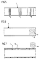
- FIG Glass fibers are spaced apart in the longitudinal direction
- Different areas 13, 14, 15 are provided, in which in the longitudinal direction periodic changes in the refractive index of the fiber occur.
- These can be generated, for example, by one, for example quartz glass fiber doped with germanium dioxide via a microlithographic Mask with ultraviolet light of 240 nm wavelength is irradiated. This creates one in each area 13, 14, 15 Arrangement of a Bragg grating, the periodicity and thus the Lattice constant in different areas 13, 14, 15 different to get voted.
- each of these Bragg gratings an interference radiation very specific wavelength is reflected, this wavelength is dependent on the periodicity of the lattice and thus also changes when this the periodicity changes.
- Such a change in periodicity or Lattice constant can be caused by external influences, for example by stretching the glass fiber, by bending the glass fiber, by heating etc. Since in each area 13, 14, 15 only radiation of a certain one Wavelength is reflected, you can look at the wavelength of the reflected radiation immediately read in which area a Reflection has occurred, also gives the shift in wavelength Information about changes in the grid spacing in these areas, so for example about the stretching of the glass fiber in certain areas.
- Measuring device can make statements about it from the reflected radiation make how large an elongation is in each of the areas 13, 14, 15. This is particularly useful when using several Such glass fibers provide precise information about the deformation of the Implants 1 in the body and thus, for example, on the healing process when bone fragments grow together. The stretch due to the forces exerted will be greatest when the Bone fragments have not yet grown together and they will continuously decrease with the healing progress.
- the radiation emitted in this way can be determined by the measuring device.
- Environmental influences, for example certain chemical substances in the environment of the area 16 can influence the fluorescence, for example the fluorescence intensity can be reduced or the fluorescence be completely deleted.
- the measuring device receives on this Wise information about the presence of certain chemical substances in the vicinity of area 16.
- the glass fiber 7 has a coating 18 envelops the outlet of the guided through the glass fiber 7 prevents electromagnetic radiation.
- This coating can react with chemical substances 19 in the environment and itself implement so that the exit properties of the electromagnetic Radiation can be changed in the area where the chemical Substance 19 is located, and in this way you get one again Change in reflected radiation depending on certain chemical substances 19 in the vicinity of the glass fiber 7.
- the flat ground end 20 of the glass fiber 7 also a flat ground end 21 one Glass fiber piece 22 opposite, between the ends 20 and 21st a very narrow gap 23 is formed, for example the gap width A are of the order of 50 mm.
- This arrangement forms a Fabry-Pérot interferometer and reflects radiation from a whole certain wavelength, this depends on the gap width A. Moving the two ends 20 and 21 relative to each other results there is also a shift in the wavelength of the reflected Radiation, and this can be determined very sensitively. This too For example, stretching of the implant can result in the glass fiber 7 and the glass fiber piece 22 are transmitted without notice more.
- an active layer 24 is inserted into the gap 23, which their dimension, for example their volume, as a function of environmental influences changes. It can be, for example porous structure act when liquid enters the pores swells. This changes the gap width B and this leads to a change in the wavelength of the Fabry-Pérot arrangement reflected radiation.
- FIGS. 8 and 9 thus form one Sensor member 12, which via the glass fiber 7 with the measuring device 11 is connected in the exemplary embodiments of FIGS. 5 to 7, however, the glass fiber 7 itself is a sensor element, it is about So here are glass fibers that are themselves sensor fibers.
- the glass fiber 7 is a sensor element 12 in the form of a pressure sensor 25.
- connection of the transmission element 8 with the measuring device 11 is in the embodiment in the Figure 3 symbolized by a line 10, it can be a physical line or around a wireless transmission link act.
- a radiation source 29 provided with one or more glass fibers 30 in connection stand, which are embedded in the plastic material 6 of the implant 1 are.
- a radiation source 29 provided with one or more glass fibers 30 in connection stand, which are embedded in the plastic material 6 of the implant 1 are.
- FIG. 3 there is only one such glass fiber 30 shown, which is directly connected to the radiation source 29 is to be understood only as a schematic representation.
- several glass fibers 30 can be provided, which are similar How the glass fibers 7 are connected to the measuring device are in turn connected to the radiation source 29, that is to say via transmission elements, which are located in the body or outside could, etc.
- the radiation source 29 can be an electromagnetic one in the glass fibers 30 Feed in radiation that emerges inside the implant 1 and creates a direct influence on the environment there, for example a heating of the surrounding plastic material 6 or but additional curing through increased polymerization or but a dissolution of polymerization compounds etc.
- electromagnetic radiation is an influence the physical data of the plastic material 6 and possibly the Environment of the implant 1, for example, the strength of the Implants are increased or decreased locally or across the board.
- the location of exposure can be determined by arranging the Glass fibers 30 in the implant 1 determine the type of action an appropriate selection of a particular radiation.
- the radiation source 29 can be completely independent of the measuring device 13 can be activated, but it is particularly advantageous if, how 3, a controller 31 is assigned to the radiation source 29 which is the radiation source 29 as a function of the measurement data the measuring device 11 switches on and off. To this end is the measuring device 11 via a line 28 with the controller 31 connected.
- the measuring device 11 determines that the elongation of the Implant 1 decreases in a certain area, this is a Signs that part of the power transmission through healing Bone fragments has been taken over, it can then be fed in of electromagnetic radiation in glass fibers 30 the strength of the implant 1 by dissolving part of the plastic material 6 are reduced so that the support function of the implant 1 corresponding to the increase in the stability of the bone connection decreases. This is an optimal adaptation of these sizes to each other possible, moreover, it is conducive to healing if the bone connection is increasingly burdened according to the healing process.
- the introduction of the the radiation source 29 generated radiation via glass fibers 30, the are different from the glass fibers 7 of the measuring device.
- the optical switch 33 can optionally also be operated automatically be, so that it is ensured that, for example, alternately A measurement of the physical condition is carried out via the glass fiber 7 and radiant energy to influence the glass fiber environment is irradiated.
Landscapes
- Health & Medical Sciences (AREA)
- Life Sciences & Earth Sciences (AREA)
- Orthopedic Medicine & Surgery (AREA)
- Engineering & Computer Science (AREA)
- Surgery (AREA)
- General Health & Medical Sciences (AREA)
- Veterinary Medicine (AREA)
- Physics & Mathematics (AREA)
- Heart & Thoracic Surgery (AREA)
- Medical Informatics (AREA)
- Molecular Biology (AREA)
- Animal Behavior & Ethology (AREA)
- Public Health (AREA)
- Biomedical Technology (AREA)
- Pathology (AREA)
- Biophysics (AREA)
- Chemical & Material Sciences (AREA)
- Neurology (AREA)
- Nuclear Medicine, Radiotherapy & Molecular Imaging (AREA)
- Analytical Chemistry (AREA)
- Chemical Kinetics & Catalysis (AREA)
- Plasma & Fusion (AREA)
- Computer Networks & Wireless Communication (AREA)
- Biochemistry (AREA)
- General Physics & Mathematics (AREA)
- Immunology (AREA)
- Measuring And Recording Apparatus For Diagnosis (AREA)
- Materials For Medical Uses (AREA)
- Prostheses (AREA)
- Electrotherapy Devices (AREA)
Description
- Figur 1:
- eine schematische Ansicht eines Implantats in Form einer Knochenplatte mit einer drahtlosen Verbindung zu einer Meßeinrichtung;
- Figur 2:
- eine schematische Ansicht eines plattenförmigen Implantates mit einer netzförmigen Glasfaserverstärkung;
- Figur 3:
- eine schematische Ansicht eines Implantats in Form einer Knochenplatte mit einer an mehrere Glasfasern angeschlossenen Meßeinrichtung und mit einer Strahlungsquelle zur Einführung von Strahlung in eine nicht mit der Meßeinrichtung verbundene Glasfaser;
- Figur 4:
- eine Ansicht ähnlich Figur 3 mit einer Schalteinrichtung zur wahlweisen Verbindung von Glasfasern im Implantat mit der Meßeinrichtung oder mit der Strahlungsquelle;
- Figur 5:
- eine schematische Seitenansicht einer Glasfaser mit Bragg-Gitter-Bereichen unterschiedlicher Periodizität;
- Figur 6:
- eine schematische Seitenansicht einer Glasfaser mit eingebetteten fluoreszierenden Farbstoffpartikeln;
- Figur 7:
- eine schematische Seitenansicht einer Glasfaser mit einer Ummantelung mit veränderlichen Transmissionseigenschaften;
- Figur 8:
- eine schematische Seitenansicht eines mit einer Glasfaser verbundenen Fabry-Pérot-Interferometers mit zwei gegeneinander bewegten Glasfaserstükken;
- Figur 9:
- eine Ansicht ähnlich Figur 8 mit einer dimensionsveränderlichen aktiven Schicht und
- Figur 10:
- eine schematische Seitenansicht einer Glasfaser mit einem Membrandrucksensor.
Claims (25)
- Medizinisches Implantatsystem mit einem Implantat (1) aus einem Verbundwerkstoff, in welchen Glasfasern (7) eingebettet sind, wobei ein in das Implantat (1) eingebettetes, mindestens eine der Glasfasern (7) umfassendes Sensorelement mit einer Meßeinrichtung (11) verbunden ist, die eine physikalische Eigenschafts des Sensorelements oder dessen Umgebung oder deren Änderung bestimmt, dadurch gekennzeichnet, daß die Glasfasern (7) in Form eines Gewebes, eines Gewirkes oder eines Vlieses als mechanische Verstärkung in den Verbundwerkstoff eingebettet sind.
- Implantatsystem nach Anspruch 1, dadurch gekennzeichnet, daß die Glasfasern (7) im Verbundwerkstoff über die gesamte Ausdehnung des Implantates (1) verteilt sind.
- Implantatsystem nach einem der voranstehenden Ansprüche, dadurch gekennzeichnet, daß die Meßeinrichtung (11) elektromagnetische Strahlung in das Sensorelement einspeist und aus der Art der durchgehenden und/oder reflektierenden Strahlung physikalische Eigenschaften des Sensorelementes oder von dessen Umgebung bestimmt.
- Implantatsystem nach Anspruch 3, dadurch gekennzeichnet, daß die Glasfaser (7) des Sensorelementes mit einer strahlungsreflektierenden Beschichtung (18) versehen ist.
- Implantatsystem nach einem der voranstehenden Ansprüche, dadurch gekennzeichnet, daß das Sensorelement im wesentlichen aus der eine Sensorfaser ausbildenden Glasfaser (7) besteht.
- Implantatsystem nach Anspruch 5, dadurch gekennzeichnet, daß in die Sensorfaser mindestens ein als Bragg-Gitter wirkender Bereich (13, 14, 15) eingearbeitet ist.
- Implantatsystem nach 5, dadurch gekennzeichnet, daß in die Sensorfaser eine durch die eingespeiste elektromagnetische Strahlung zur Fluoreszenz angeregte Substanz (17) eingebettet ist, deren Fluoreszenzeigenschaften unter Einwirkung der chemischen Umgebung außerhalb der Sensorfaser Änderungen erfahren.
- Implantatsystem nach Anspruch 4 und 5, dadurch gekennzeichnet, daß die strahlungsreflektierende Beschichtung (18) aus einer Substanz besteht, die unter Einwirkung der chemischen Umgebung (19) außerhalb der Sensorfaser das Refilexionsverhalten für die elektromagnetische Strahlung in der Sensorfaser verändert.
- Implantatsystem nach einem der Ansprüche 1 bis 3, dadurch gekennzeichnet, daß das Sensorelement die Glasfaser (7) umfaßt und ein weiteres Sensorglied (12), welches über die Glasfaser (7) mit der Meßeinrichtung (11) verbunden ist.
- Implantatsystem nach Anspruch 9 dadurch gekennzeichnet, daß das Sensorglied (12) ein Drucksensor (25) mit einer flexiblen Membran (26) und einem von dieser bewegbaren Spiegelelement (27) ist, weiches die in die Glasfaser (7) eingespeiste elektromagnetische Strahlung je nach Stellung unterschiedlich reflektiert.
- Implantatsystem nach Anspruch 9, dadurch gekennzeichnet, daß das Sensorglied (12) ein Fabry-Pérot-Interferometer ist.
- Implantatsystem nach Anspruch 11, dadurch gekennzeichnet, daß das Fabry-Pérot-Interferometer als auf das Ende (20) der Glasfaser (7) aufkontaktiertes Dünnschicht-Interferometer (21, 22, 24) ausgebildet ist, dessen aktive Schicht (24) unter dem Einfluß der Umgebung Dimensionsänderungen erfährt.
- Implantatsystem nach Anspruch 11, dadurch gekennzeichnet, daß das Fabry-Pérot-Interferometer zwei Glasfasern (7, 22) mit polierten Endflächen (20, 21) umfaßt, deren Abstand (B) durch Umgebungseinflüsse veränderbar ist.
- Implantatsystem nach einem der voranstehenden Ansprüche, dadurch gekennzeichnet, daß die Glasfaser (7) des Sensorelementes direkt mit der Meßeinrichtung (11) verbunden ist.
- Implantatsystem nach Anspruch 14, dadurch gekennzeichnet, daß die Meßeinrichtung ein in den Körper implantierbarer Mikrocontroller ist.
- Implantatsystem nach einem Ansprüche 1 bis 13, dadurch gekennzeichnet, daß die Glasfaser (7) mit einem Übertrager (8) verbunden ist, der ohne körperliche Verbindung Signale mit der Meßeinrichtung (11) austauscht.
- Implantatsystem nach Anspruch 16, dadurch gekennzeichnet, daß der Übertrager (8) in den Körper implantierbar ist.
- Implantatsystem nach Anspruch 16 oder 17, dadurch gekennzeichnet, daß der Übertrager (8) ein Transponder ist.
- Implantatsystem nach Anspruch 16 oder 17, dadurch gekennzeichnet, daß der Übertrager eine Lichtquelle ist, der ein Lichtempfänger zugeordnet ist.
- Implantatsystem nach Anspruch 19, dadurch gekennzeichnet, daß die Lichtquelle elektromagnetische Strahlung im Bereich zwischen 650 und 1000 nm aussendet.
- Implantatsystem nach einem der voranstehenden Ansprüche, dadurch gekennzeichnet, daß der Meßeinrichtung (11) ein Strahlungssender (29) zugeordnet ist, der über eine Glasfaser (7; 30) im Implantat (1) Strahlung in das Innere des Implantates (1) transportiert.
- Implantatsystem nach Anspruch 21, dadurch gekennzeichnet, daß der Transport der Strahlung über die Glasfaser (7) eines Sensorelementes erfolgt.
- Implantatsystem nach Anspruch 21, dadurch gekennzeichnet, daß der Transport der Strahlung über eine Glasfaser (30) erfolgt, die zusätzlich zu der Glasfaser (7) eines Sensorelementes in das Implantat (1) eingebettet ist.
- Implantatsystem nach einem der Ansprüche 21 bis 23, dadurch gekennzeichnet, daß Wellenlänge und Intensität der transportierten Strahlung so gewählt sind, daß die Strahlung in dem Verbundwerkstoff des Implantates mechanische und/oder stoffliche Veränderungen hervorruft.
- Implantatsystem nach einem der Ansprüche 21 bis 24, dadurch gekennzeichnet, daß der Meßeinrichtung (11) und dem Strahlungssender (29) eine Steuerung (31) zugeordnet ist, die den Strahlungssender in Abhängigkeit von den Meßgrößen der Meßeinrichtung (11) aktiviert.
Applications Claiming Priority (3)
| Application Number | Priority Date | Filing Date | Title |
|---|---|---|---|
| DE10137011 | 2001-07-28 | ||
| DE10137011A DE10137011C2 (de) | 2001-07-28 | 2001-07-28 | Medizinisches Implantatsystem |
| PCT/EP2002/007927 WO2003011133A1 (de) | 2001-07-28 | 2002-07-17 | Medizinisches implantatsystem |
Publications (2)
| Publication Number | Publication Date |
|---|---|
| EP1424937A1 EP1424937A1 (de) | 2004-06-09 |
| EP1424937B1 true EP1424937B1 (de) | 2004-11-17 |
Family
ID=32308445
Family Applications (1)
| Application Number | Title | Priority Date | Filing Date |
|---|---|---|---|
| EP02791457A Expired - Lifetime EP1424937B1 (de) | 2001-07-28 | 2002-07-17 | Medizinisches implantatsystem |
Country Status (5)
| Country | Link |
|---|---|
| US (1) | US20040204647A1 (de) |
| EP (1) | EP1424937B1 (de) |
| AT (1) | ATE282358T1 (de) |
| DE (1) | DE50201594D1 (de) |
| ES (1) | ES2232784T3 (de) |
Families Citing this family (24)
| Publication number | Priority date | Publication date | Assignee | Title |
|---|---|---|---|---|
| US8391958B2 (en) * | 2003-06-19 | 2013-03-05 | Osstell Ab | Method and arrangement relating to testing objects |
| SE0301825L (sv) * | 2003-06-19 | 2005-02-18 | Integration Diagnostics Ltd | Metod och system vid implantattest |
| DE102004006501A1 (de) * | 2004-02-10 | 2005-09-01 | Charité-Universitätsmedizin Berlin | Bauteil und Verfahren zum Zusammenbau einer Implantatanordnung |
| US20070270684A1 (en) * | 2004-06-21 | 2007-11-22 | Integration Diagnostics Ltd. | Method and Arrangement Relating to Testing Objects |
| US8388553B2 (en) | 2004-11-04 | 2013-03-05 | Smith & Nephew, Inc. | Cycle and load measurement device |
| WO2007025191A1 (en) | 2005-08-23 | 2007-03-01 | Smith & Nephew, Inc. | Telemetric orthopaedic implant |
| DE102005045739A1 (de) * | 2005-09-23 | 2007-04-19 | Universitätsklinikum Freiburg | Osteosynthesehilfsmittel |
| US7691130B2 (en) * | 2006-01-27 | 2010-04-06 | Warsaw Orthopedic, Inc. | Spinal implants including a sensor and methods of use |
| US7328131B2 (en) * | 2006-02-01 | 2008-02-05 | Medtronic, Inc. | Implantable pedometer |
| US8016859B2 (en) | 2006-02-17 | 2011-09-13 | Medtronic, Inc. | Dynamic treatment system and method of use |
| US7993269B2 (en) * | 2006-02-17 | 2011-08-09 | Medtronic, Inc. | Sensor and method for spinal monitoring |
| US9849216B2 (en) | 2006-03-03 | 2017-12-26 | Smith & Nephew, Inc. | Systems and methods for delivering a medicament |
| WO2008023708A1 (fr) * | 2006-08-22 | 2008-02-28 | Mitsubishi Electric Corporation | Appareil de traitement laser, procédé de jonction osseuse, élément d'implant, procédé de production d'un élément d'implant, et production d'un élément d'implant |
| US9445720B2 (en) | 2007-02-23 | 2016-09-20 | Smith & Nephew, Inc. | Processing sensed accelerometer data for determination of bone healing |
| CN107115591A (zh) | 2007-09-06 | 2017-09-01 | 史密夫和内修有限公司 | 用于与遥测植入物通信的系统和方法 |
| US8915866B2 (en) | 2008-01-18 | 2014-12-23 | Warsaw Orthopedic, Inc. | Implantable sensor and associated methods |
| CN102245115B (zh) | 2008-10-15 | 2016-08-24 | 史密夫和内修有限公司 | 复合内部固定架 |
| US8685093B2 (en) | 2009-01-23 | 2014-04-01 | Warsaw Orthopedic, Inc. | Methods and systems for diagnosing, treating, or tracking spinal disorders |
| US8126736B2 (en) | 2009-01-23 | 2012-02-28 | Warsaw Orthopedic, Inc. | Methods and systems for diagnosing, treating, or tracking spinal disorders |
| US8376937B2 (en) * | 2010-01-28 | 2013-02-19 | Warsaw Orhtopedic, Inc. | Tissue monitoring surgical retractor system |
| WO2013012717A2 (en) * | 2011-07-15 | 2013-01-24 | Smith & Nephew, Inc. | Fiber-reinforced composite orthopaedic device having embedded electronics |
| EP3108807A1 (de) * | 2015-06-26 | 2016-12-28 | Stryker European Holdings I, LLC | Knochenheilungssonde |
| PT3481284T (pt) | 2016-07-07 | 2021-10-14 | Univ California | Implantes utilizando retrodifusão ultrassónica para detetar sinais eletrofisiológicos |
| CN120419967B (zh) * | 2025-07-04 | 2025-10-10 | 武汉理工大学 | 基于光纤内植椎间融合器的体感知方法及系统 |
Family Cites Families (15)
| Publication number | Priority date | Publication date | Assignee | Title |
|---|---|---|---|---|
| US4895574A (en) * | 1984-06-06 | 1990-01-23 | Larry Rosenberg | Piezoelectric motivator for prosthetic devices |
| JPS61135671A (ja) * | 1984-12-04 | 1986-06-23 | 三菱鉱業セメント株式会社 | インプラント材 |
| US5561173A (en) * | 1990-06-19 | 1996-10-01 | Carolyn M. Dry | Self-repairing, reinforced matrix materials |
| CA2074289C (en) * | 1992-07-21 | 1999-09-14 | Claude Belleville | Fabry-perot optical sensing device for measuring a physical parameter |
| US5376785A (en) * | 1992-10-02 | 1994-12-27 | Chin; Philip K. | Optical displacement sensor utilizing optical diffusion |
| US5695496A (en) * | 1995-01-17 | 1997-12-09 | Smith & Nephew Inc. | Method of measuring bone strain to detect fracture consolidation |
| US5841529A (en) * | 1996-03-25 | 1998-11-24 | University Of Maryland | Fiber optic strain sensor |
| US6005242A (en) * | 1997-08-15 | 1999-12-21 | Alconi Sensline | Environmental media and pressure sensor |
| WO2000038570A1 (en) * | 1998-12-31 | 2000-07-06 | Ball Semiconductor, Inc. | Miniature implanted orthopedic sensors |
| JP3519333B2 (ja) * | 2000-02-10 | 2004-04-12 | エヌ・ティ・ティ・アドバンステクノロジ株式会社 | 光ファイバセンサ |
| US7050661B2 (en) * | 2000-03-27 | 2006-05-23 | Tml Photonics, Inc. | Process to create artificial nerves for biomechanical systems using optical waveguide network |
| US6539947B2 (en) * | 2000-12-12 | 2003-04-01 | International Business Machines Corporation | Apparatus, system, method and computer program product for controlling bio-enhancement implants |
| US7344539B2 (en) * | 2001-03-30 | 2008-03-18 | Depuy Acromed, Inc. | Intervertebral connection system |
| EP1513584A2 (de) * | 2002-06-04 | 2005-03-16 | Cyberkinetics, Inc. | Optisch verbundene implantate, darauf bezogene systeme und deren verwendung |
| US6761741B2 (en) * | 2002-06-10 | 2004-07-13 | Kazuho Iesaka | Prosthetic joint |
-
2002
- 2002-07-17 ES ES02791457T patent/ES2232784T3/es not_active Expired - Lifetime
- 2002-07-17 DE DE50201594T patent/DE50201594D1/de not_active Expired - Fee Related
- 2002-07-17 AT AT02791457T patent/ATE282358T1/de not_active IP Right Cessation
- 2002-07-17 EP EP02791457A patent/EP1424937B1/de not_active Expired - Lifetime
-
2004
- 2004-01-26 US US10/765,724 patent/US20040204647A1/en not_active Abandoned
Also Published As
| Publication number | Publication date |
|---|---|
| DE50201594D1 (de) | 2004-12-23 |
| US20040204647A1 (en) | 2004-10-14 |
| ES2232784T3 (es) | 2005-06-01 |
| ATE282358T1 (de) | 2004-12-15 |
| EP1424937A1 (de) | 2004-06-09 |
Similar Documents
| Publication | Publication Date | Title |
|---|---|---|
| EP1424937A1 (de) | Medizinisches implantatsystem | |
| EP0354362B1 (de) | Verfahren zum Aufbringen und Lesen von und Flasche mit optisch lesbaren Codemarkierungen | |
| DE2343869C3 (de) | Vorrichtung zur Messung einer Eigenschaft von foUenartigem Material | |
| DE10011284B4 (de) | Vorrichtung für eine In-vivo Messung der Konzentration eines Inhaltsstoffs einer Körperflüssigkeit | |
| DE69417026T2 (de) | Verfahren zur herstellung weichen tissue-papiers | |
| DE60130351T2 (de) | Faseroptischer verbinder und optisches bauelement | |
| EP3359948B1 (de) | Vorrichtung und verfahren zum analysieren eines stoffs | |
| EP1827866B1 (de) | Sicherheitsdokument mit lichtquelle und lichtverarbeitungsvorrichtung | |
| EP1998670A1 (de) | Vorrichtung, sensor, sensorelement sowie verfahren zur vermessung des wirbelsäulenverlaufs und von verlaufsänderungen der wirbelsäule | |
| DE102012200387A1 (de) | Walze mit Sensoren für bahnverarbeitende Maschine | |
| EP2718692A1 (de) | Vorrichtung und verfahren zur bestimmung von material-eigenschaften einer substrat-probe im tera-hertz-frequenzspektrum | |
| CA2333111A1 (en) | Composite of polymer or ceramic materials and component made of such a composite | |
| DE10014542A1 (de) | Erfassungssystem und Erfassungsverfahren für chirurgische Instrumente und Materialien | |
| WO2001090697A1 (de) | Optischer verformungssensor mit funktionsüberprüfung durch verschiedene wellenlängen für seitencrash | |
| DE69703045T2 (de) | Sicherheitsmarkierungssystem | |
| EP1716820A2 (de) | Gerät zum Polymerisieren von polymerisierbarem Dentalmaterial sowie Verfahren zur Bestimmung des Polymerisationsgrades | |
| DE10137011C2 (de) | Medizinisches Implantatsystem | |
| EP3811135A1 (de) | Vorrichtung und verfahren zur ausrichtung von polarisationserhaltenden lichtleitfasern | |
| EP2703772B1 (de) | Sensor zum Erfassen einer laufenden Warenbahn | |
| WO2014063843A1 (de) | Sensorelement mit einer photonischen kristallanordnung | |
| EP3047793B1 (de) | Wundverband | |
| DE102012219643B4 (de) | Sensorelement mit einer photonischen kristallanordnung | |
| EP1451019A1 (de) | Gegenstand, insbesondere wert- und sicherheitsdokument mit einem sicherheitsmerkmal | |
| EP4257081B1 (de) | Ophthalmologisches implantat mit einem grundkörper und einem kraftsensor sowie vorrichtung zum ermitteln einer kraft, welche auf ein ophthalmologisches implantat einwirkt | |
| DE112022000896T5 (de) | Laserscanningverfahren, laserbestrahlungsvorrichtung und laserscanningprogramm |
Legal Events
| Date | Code | Title | Description |
|---|---|---|---|
| PUAI | Public reference made under article 153(3) epc to a published international application that has entered the european phase |
Free format text: ORIGINAL CODE: 0009012 |
|
| GRAP | Despatch of communication of intention to grant a patent |
Free format text: ORIGINAL CODE: EPIDOSNIGR1 |
|
| 17P | Request for examination filed |
Effective date: 20040116 |
|
| AK | Designated contracting states |
Kind code of ref document: A1 Designated state(s): AT BE BG CH CY CZ DE DK EE ES FI FR GB GR IE IT LI LU MC NL PT SE SK TR |
|
| AX | Request for extension of the european patent |
Extension state: AL LT LV MK RO SI |
|
| GRAS | Grant fee paid |
Free format text: ORIGINAL CODE: EPIDOSNIGR3 |
|
| GRAA | (expected) grant |
Free format text: ORIGINAL CODE: 0009210 |
|
| AK | Designated contracting states |
Kind code of ref document: B1 Designated state(s): AT BE BG CH CY CZ DE DK EE ES FI FR GB GR IE IT LI LU MC NL PT SE SK TR |
|
| PG25 | Lapsed in a contracting state [announced via postgrant information from national office to epo] |
Ref country code: CZ Free format text: LAPSE BECAUSE OF FAILURE TO SUBMIT A TRANSLATION OF THE DESCRIPTION OR TO PAY THE FEE WITHIN THE PRESCRIBED TIME-LIMIT Effective date: 20041117 Ref country code: FI Free format text: LAPSE BECAUSE OF FAILURE TO SUBMIT A TRANSLATION OF THE DESCRIPTION OR TO PAY THE FEE WITHIN THE PRESCRIBED TIME-LIMIT Effective date: 20041117 Ref country code: EE Free format text: LAPSE BECAUSE OF FAILURE TO SUBMIT A TRANSLATION OF THE DESCRIPTION OR TO PAY THE FEE WITHIN THE PRESCRIBED TIME-LIMIT Effective date: 20041117 Ref country code: BG Free format text: LAPSE BECAUSE OF FAILURE TO SUBMIT A TRANSLATION OF THE DESCRIPTION OR TO PAY THE FEE WITHIN THE PRESCRIBED TIME-LIMIT Effective date: 20041117 Ref country code: NL Free format text: LAPSE BECAUSE OF FAILURE TO SUBMIT A TRANSLATION OF THE DESCRIPTION OR TO PAY THE FEE WITHIN THE PRESCRIBED TIME-LIMIT Effective date: 20041117 Ref country code: IE Free format text: LAPSE BECAUSE OF FAILURE TO SUBMIT A TRANSLATION OF THE DESCRIPTION OR TO PAY THE FEE WITHIN THE PRESCRIBED TIME-LIMIT Effective date: 20041117 Ref country code: TR Free format text: LAPSE BECAUSE OF FAILURE TO SUBMIT A TRANSLATION OF THE DESCRIPTION OR TO PAY THE FEE WITHIN THE PRESCRIBED TIME-LIMIT Effective date: 20041117 Ref country code: SK Free format text: LAPSE BECAUSE OF FAILURE TO SUBMIT A TRANSLATION OF THE DESCRIPTION OR TO PAY THE FEE WITHIN THE PRESCRIBED TIME-LIMIT Effective date: 20041117 |
|
| REG | Reference to a national code |
Ref country code: GB Ref legal event code: FG4D Free format text: NOT ENGLISH |
|
| REG | Reference to a national code |
Ref country code: CH Ref legal event code: NV Representative=s name: ISLER & PEDRAZZINI AG Ref country code: CH Ref legal event code: EP |
|
| REG | Reference to a national code |
Ref country code: IE Ref legal event code: FG4D Free format text: GERMAN |
|
| REF | Corresponds to: |
Ref document number: 50201594 Country of ref document: DE Date of ref document: 20041223 Kind code of ref document: P |
|
| GBT | Gb: translation of ep patent filed (gb section 77(6)(a)/1977) | ||
| PG25 | Lapsed in a contracting state [announced via postgrant information from national office to epo] |
Ref country code: DK Free format text: LAPSE BECAUSE OF FAILURE TO SUBMIT A TRANSLATION OF THE DESCRIPTION OR TO PAY THE FEE WITHIN THE PRESCRIBED TIME-LIMIT Effective date: 20050217 Ref country code: SE Free format text: LAPSE BECAUSE OF FAILURE TO SUBMIT A TRANSLATION OF THE DESCRIPTION OR TO PAY THE FEE WITHIN THE PRESCRIBED TIME-LIMIT Effective date: 20050217 Ref country code: GR Free format text: LAPSE BECAUSE OF FAILURE TO SUBMIT A TRANSLATION OF THE DESCRIPTION OR TO PAY THE FEE WITHIN THE PRESCRIBED TIME-LIMIT Effective date: 20050217 |
|
| NLV1 | Nl: lapsed or annulled due to failure to fulfill the requirements of art. 29p and 29m of the patents act | ||
| REG | Reference to a national code |
Ref country code: ES Ref legal event code: FG2A Ref document number: 2232784 Country of ref document: ES Kind code of ref document: T3 |
|
| REG | Reference to a national code |
Ref country code: IE Ref legal event code: FD4D |
|
| PG25 | Lapsed in a contracting state [announced via postgrant information from national office to epo] |
Ref country code: CY Free format text: LAPSE BECAUSE OF FAILURE TO SUBMIT A TRANSLATION OF THE DESCRIPTION OR TO PAY THE FEE WITHIN THE PRESCRIBED TIME-LIMIT Effective date: 20050717 Ref country code: LU Free format text: LAPSE BECAUSE OF NON-PAYMENT OF DUE FEES Effective date: 20050717 Ref country code: AT Free format text: LAPSE BECAUSE OF NON-PAYMENT OF DUE FEES Effective date: 20050717 |
|
| PG25 | Lapsed in a contracting state [announced via postgrant information from national office to epo] |
Ref country code: MC Free format text: LAPSE BECAUSE OF NON-PAYMENT OF DUE FEES Effective date: 20050731 Ref country code: BE Free format text: LAPSE BECAUSE OF NON-PAYMENT OF DUE FEES Effective date: 20050731 |
|
| PLBE | No opposition filed within time limit |
Free format text: ORIGINAL CODE: 0009261 |
|
| STAA | Information on the status of an ep patent application or granted ep patent |
Free format text: STATUS: NO OPPOSITION FILED WITHIN TIME LIMIT |
|
| ET | Fr: translation filed | ||
| 26N | No opposition filed |
Effective date: 20050818 |
|
| PG25 | Lapsed in a contracting state [announced via postgrant information from national office to epo] |
Ref country code: DE Free format text: LAPSE BECAUSE OF NON-PAYMENT OF DUE FEES Effective date: 20060201 |
|
| REG | Reference to a national code |
Ref country code: CH Ref legal event code: PCAR Free format text: ISLER & PEDRAZZINI AG;POSTFACH 1772;8027 ZUERICH (CH) |
|
| BERE | Be: lapsed |
Owner name: *AESCULAP A.G. & CO. K.G. Effective date: 20050731 |
|
| PG25 | Lapsed in a contracting state [announced via postgrant information from national office to epo] |
Ref country code: PT Free format text: LAPSE BECAUSE OF NON-PAYMENT OF DUE FEES Effective date: 20050417 |
|
| PG25 | Lapsed in a contracting state [announced via postgrant information from national office to epo] |
Ref country code: IT Free format text: LAPSE BECAUSE OF NON-PAYMENT OF DUE FEES Effective date: 20120717 |
|
| PGRI | Patent reinstated in contracting state [announced from national office to epo] |
Ref country code: IT Effective date: 20131025 |
|
| PGFP | Annual fee paid to national office [announced via postgrant information from national office to epo] |
Ref country code: CH Payment date: 20140722 Year of fee payment: 13 |
|
| PGFP | Annual fee paid to national office [announced via postgrant information from national office to epo] |
Ref country code: IT Payment date: 20140728 Year of fee payment: 13 |
|
| REG | Reference to a national code |
Ref country code: CH Ref legal event code: PL |
|
| PG25 | Lapsed in a contracting state [announced via postgrant information from national office to epo] |
Ref country code: IT Free format text: LAPSE BECAUSE OF NON-PAYMENT OF DUE FEES Effective date: 20150717 Ref country code: LI Free format text: LAPSE BECAUSE OF NON-PAYMENT OF DUE FEES Effective date: 20150731 Ref country code: CH Free format text: LAPSE BECAUSE OF NON-PAYMENT OF DUE FEES Effective date: 20150731 |
|
| REG | Reference to a national code |
Ref country code: FR Ref legal event code: PLFP Year of fee payment: 15 |
|
| PGFP | Annual fee paid to national office [announced via postgrant information from national office to epo] |
Ref country code: GB Payment date: 20160722 Year of fee payment: 15 |
|
| PGFP | Annual fee paid to national office [announced via postgrant information from national office to epo] |
Ref country code: FR Payment date: 20160722 Year of fee payment: 15 |
|
| PGFP | Annual fee paid to national office [announced via postgrant information from national office to epo] |
Ref country code: ES Payment date: 20160722 Year of fee payment: 15 |
|
| GBPC | Gb: european patent ceased through non-payment of renewal fee |
Effective date: 20170717 |
|
| REG | Reference to a national code |
Ref country code: FR Ref legal event code: ST Effective date: 20180330 |
|
| PG25 | Lapsed in a contracting state [announced via postgrant information from national office to epo] |
Ref country code: GB Free format text: LAPSE BECAUSE OF NON-PAYMENT OF DUE FEES Effective date: 20170717 |
|
| PG25 | Lapsed in a contracting state [announced via postgrant information from national office to epo] |
Ref country code: FR Free format text: LAPSE BECAUSE OF NON-PAYMENT OF DUE FEES Effective date: 20170731 |
|
| REG | Reference to a national code |
Ref country code: ES Ref legal event code: FD2A Effective date: 20181030 |
|
| PG25 | Lapsed in a contracting state [announced via postgrant information from national office to epo] |
Ref country code: ES Free format text: LAPSE BECAUSE OF NON-PAYMENT OF DUE FEES Effective date: 20170718 |