EP1424706A1 - Apparatus and method of manufacturing coils - Google Patents
Apparatus and method of manufacturing coils Download PDFInfo
- Publication number
- EP1424706A1 EP1424706A1 EP03252611A EP03252611A EP1424706A1 EP 1424706 A1 EP1424706 A1 EP 1424706A1 EP 03252611 A EP03252611 A EP 03252611A EP 03252611 A EP03252611 A EP 03252611A EP 1424706 A1 EP1424706 A1 EP 1424706A1
- Authority
- EP
- European Patent Office
- Prior art keywords
- adhesive
- wire
- coil
- winding core
- coat
- Prior art date
- Legal status (The legal status is an assumption and is not a legal conclusion. Google has not performed a legal analysis and makes no representation as to the accuracy of the status listed.)
- Withdrawn
Links
Images




Classifications
-
- H—ELECTRICITY
- H01—ELECTRIC ELEMENTS
- H01F—MAGNETS; INDUCTANCES; TRANSFORMERS; SELECTION OF MATERIALS FOR THEIR MAGNETIC PROPERTIES
- H01F41/00—Apparatus or processes specially adapted for manufacturing or assembling magnets, inductances or transformers; Apparatus or processes specially adapted for manufacturing materials characterised by their magnetic properties
- H01F41/02—Apparatus or processes specially adapted for manufacturing or assembling magnets, inductances or transformers; Apparatus or processes specially adapted for manufacturing materials characterised by their magnetic properties for manufacturing cores, coils, or magnets
- H01F41/04—Apparatus or processes specially adapted for manufacturing or assembling magnets, inductances or transformers; Apparatus or processes specially adapted for manufacturing materials characterised by their magnetic properties for manufacturing cores, coils, or magnets for manufacturing coils
-
- H—ELECTRICITY
- H01—ELECTRIC ELEMENTS
- H01F—MAGNETS; INDUCTANCES; TRANSFORMERS; SELECTION OF MATERIALS FOR THEIR MAGNETIC PROPERTIES
- H01F41/00—Apparatus or processes specially adapted for manufacturing or assembling magnets, inductances or transformers; Apparatus or processes specially adapted for manufacturing materials characterised by their magnetic properties
- H01F41/02—Apparatus or processes specially adapted for manufacturing or assembling magnets, inductances or transformers; Apparatus or processes specially adapted for manufacturing materials characterised by their magnetic properties for manufacturing cores, coils, or magnets
- H01F41/04—Apparatus or processes specially adapted for manufacturing or assembling magnets, inductances or transformers; Apparatus or processes specially adapted for manufacturing materials characterised by their magnetic properties for manufacturing cores, coils, or magnets for manufacturing coils
- H01F41/12—Insulating of windings
- H01F41/122—Insulating between turns or between winding layers
-
- H—ELECTRICITY
- H01—ELECTRIC ELEMENTS
- H01F—MAGNETS; INDUCTANCES; TRANSFORMERS; SELECTION OF MATERIALS FOR THEIR MAGNETIC PROPERTIES
- H01F41/00—Apparatus or processes specially adapted for manufacturing or assembling magnets, inductances or transformers; Apparatus or processes specially adapted for manufacturing materials characterised by their magnetic properties
- H01F41/02—Apparatus or processes specially adapted for manufacturing or assembling magnets, inductances or transformers; Apparatus or processes specially adapted for manufacturing materials characterised by their magnetic properties for manufacturing cores, coils, or magnets
- H01F41/04—Apparatus or processes specially adapted for manufacturing or assembling magnets, inductances or transformers; Apparatus or processes specially adapted for manufacturing materials characterised by their magnetic properties for manufacturing cores, coils, or magnets for manufacturing coils
- H01F41/06—Coil winding
- H01F41/082—Devices for guiding or positioning the winding material on the former
-
- Y—GENERAL TAGGING OF NEW TECHNOLOGICAL DEVELOPMENTS; GENERAL TAGGING OF CROSS-SECTIONAL TECHNOLOGIES SPANNING OVER SEVERAL SECTIONS OF THE IPC; TECHNICAL SUBJECTS COVERED BY FORMER USPC CROSS-REFERENCE ART COLLECTIONS [XRACs] AND DIGESTS
- Y10—TECHNICAL SUBJECTS COVERED BY FORMER USPC
- Y10T—TECHNICAL SUBJECTS COVERED BY FORMER US CLASSIFICATION
- Y10T29/00—Metal working
- Y10T29/49—Method of mechanical manufacture
- Y10T29/49002—Electrical device making
- Y10T29/4902—Electromagnet, transformer or inductor
-
- Y—GENERAL TAGGING OF NEW TECHNOLOGICAL DEVELOPMENTS; GENERAL TAGGING OF CROSS-SECTIONAL TECHNOLOGIES SPANNING OVER SEVERAL SECTIONS OF THE IPC; TECHNICAL SUBJECTS COVERED BY FORMER USPC CROSS-REFERENCE ART COLLECTIONS [XRACs] AND DIGESTS
- Y10—TECHNICAL SUBJECTS COVERED BY FORMER USPC
- Y10T—TECHNICAL SUBJECTS COVERED BY FORMER US CLASSIFICATION
- Y10T29/00—Metal working
- Y10T29/49—Method of mechanical manufacture
- Y10T29/49002—Electrical device making
- Y10T29/4902—Electromagnet, transformer or inductor
- Y10T29/49071—Electromagnet, transformer or inductor by winding or coiling
-
- Y—GENERAL TAGGING OF NEW TECHNOLOGICAL DEVELOPMENTS; GENERAL TAGGING OF CROSS-SECTIONAL TECHNOLOGIES SPANNING OVER SEVERAL SECTIONS OF THE IPC; TECHNICAL SUBJECTS COVERED BY FORMER USPC CROSS-REFERENCE ART COLLECTIONS [XRACs] AND DIGESTS
- Y10—TECHNICAL SUBJECTS COVERED BY FORMER USPC
- Y10T—TECHNICAL SUBJECTS COVERED BY FORMER US CLASSIFICATION
- Y10T29/00—Metal working
- Y10T29/53—Means to assemble or disassemble
- Y10T29/5313—Means to assemble electrical device
- Y10T29/532—Conductor
Definitions
- the present invention relates to an apparatus and method of manufacturing coils, and more particularly, to an apparatus and method of manufacturing coils to form a uniform coat when forming an insulating coat on a coil, thereby improving operational reliability of the coil.
- high voltage of over about 2000 V is induced in a coil used in a high voltage transformer (HVT) to drive a magnetron of a microwave oven.
- HVT high voltage transformer
- the coil of the high voltage transformer is electrically insulated using an insulating paper or a resin coat.
- Figure 1 shows a conventional apparatus to form an insulating resin coat on a coil for high voltage transformers
- Figure 2 shows a coil on which an insulating resin coat is formed.
- a coil 102 having a plurality of terminals 104 is inserted into a cavity 112 of a mold 106 and a resin is injected into the cavity 112, a resin coat 202 is formed on the coil 102 as shown in Figure 2.
- the resin coat 202 is required to form a uniform thickness to completely insulate the coil 102.
- the thickness of the resin coat 202 is not uniform, a desired insulating effect is not achieved, thereby causing damage to a machine employing the coil 102.
- a plurality of spacing protrusions 110 are formed on the wall surfaces 108 of the cavity 112, to face an inside of the cavity 112. Because of the spacing protrusions 110, the uniform interval between the wall surfaces 108 of the cavity 112 and the coil 102 inserted into the cavity 112 is desirably maintained, thereby forming the resin coat 202 having a uniform thickness, and producing a desired resin-coated coil 204.
- the coil 102 when the coil 102 is inserted into the conventional apparatus which forms insulating resin coats on coils for high voltage transformers, and a coat is formed on the coil 102 by injecting a thermoplastic resin, the coil 102 is often entangled or swells up by injection pressure. The coat is thereby not formed in a uniform thickness. If the insulating coat does not have a uniform thickness, it is almost impossible to ensure desired operational reliability of the coil 102.
- an apparatus to manufacture coils including a winding core to be wound around with a wire, and an adhesive supply unit to coat the wire to be wound around the winding core with an adhesive to produce a coil.
- a method of manufacturing coils including coating a wire with an adhesive, and winding the wire coated with the adhesive around a winding core to produce a coil.
- a method of manufacturing coils including coating an entire wire with an adhesive, and winding the wire around a winding core to produce a coil.
- a method of manufacturing coils including coating a part of a wire with an adhesive, and winding the wire around a winding core to produce a coil.
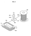
- FIG 3 is a perspective view of an apparatus to manufacture coils, according to an embodiment of the present invention.
- a wire 302a from a coil drum 302 is wound around a winding core 310, producing a coil 304 having a desired shape and a desired number of windings.
- the winding core 310 rotates about a vertical axis thereof, as shown by an arrow H in Figure 3, the coil drum 302 simultaneously rotates by rotation of the winding core 310 in the same direction.
- the wire 302a is wound around the winding core 310.
- the winding core 310 reciprocates in a vertical direction (V) within a predetermined range, thus the wire 302a wound around the winding core 310 forms layers.
- V vertical direction
- an adhesive 308 supplied from an adhesive supply unit 306 is coated on the wire 302a.
- a contact pad 312, which has a soft texture and is capable of absorbing the adhesive, is installed under the adhesive supply unit 306.
- the wire 302a unwound from the coil drum 302 is coated with the adhesive 308 while passing over the contact pad 312 such that the wire 302a is in contact with the contact pad 312.
- the wire 302a coated with the adhesive 308 is then wound around the winding core 310, thus producing the coil 304.
- the coil 304 is cohesive by the coated adhesive 308 and thus, is not entangled or loosened.
- Preferred examples of adhesives which are useful in the present invention include adhesives having insulating capacity, such as varnish.
- FIGS 4 and 5 are flowcharts showing methods of manufacturing coils according to various embodiments of the present invention.
- an adhesive is coated on an entire wire.
- operation 402 it is primarily determined whether winding of the wire is started.
- an adhesive is coated on the wire to be wound around a winding core in operation 404.
- the coating with the adhesive is stopped in operation 408.
- an adhesive-drying work is started in operation 410.
- only a predetermined length of a wire corresponding to the last three layers of total windings is coated with an adhesive.
- the wire starts to be wound around a winding core in operation 502.
- a remaining part of the wire to be wound around the winding core is coated with the adhesive in operation 506.
- the coating with the adhesive is stopped in operation 510.
- an adhesive-drying work is started in operation 512.
- a resulting coil may be dried in a drying furnace, or by using warm air supplied by a fan heater.
- the resulting coil may be dried by directly applying DC power to the coil and thus, generating heat in the coil itself.
- the apparatus and method of manufacturing coils according to the present invention coats a wire with an adhesive to make the resulting wire cohesive, thus preventing the wire wound around the winding core from being entangled or loosened, and forming a uniform coat to improve an operational reliability of the coils.
Landscapes
- Engineering & Computer Science (AREA)
- Power Engineering (AREA)
- Manufacturing & Machinery (AREA)
- Insulating Of Coils (AREA)
Abstract
An apparatus and method of manufacturing coils allows
an insulating coat to be uniformly formed on a coil to
improve an operational reliability of the coil. The
apparatus is configured to wind a wire (302a) around a
winding core (310), and equipped with an adhesive supply
unit (306) to coat an adhesive (308) on the wire (302a) to
be wound around the winding core (310), allowing the wound
wire (302a) to have a coil cohesive power. The method of
manufacturing coils includes coating the adhesive (308) on
the wire (302a), and winding the wire (302a) around the
winding core (310). The adhesive (308) may be coated on
the entire wire (302a) or a part of the wire (302a).
Description
- The present invention relates to an apparatus and method of manufacturing coils, and more particularly, to an apparatus and method of manufacturing coils to form a uniform coat when forming an insulating coat on a coil, thereby improving operational reliability of the coil.
- Generally, high voltage of over about 2000 V is induced in a coil used in a high voltage transformer (HVT) to drive a magnetron of a microwave oven. For this reason, the coil of the high voltage transformer is electrically insulated using an insulating paper or a resin coat.
- Figure 1 shows a conventional apparatus to form an insulating resin coat on a coil for high voltage transformers, while Figure 2 shows a coil on which an insulating resin coat is formed. As shown in Figure 1, when a
coil 102 having a plurality ofterminals 104 is inserted into acavity 112 of amold 106 and a resin is injected into thecavity 112, aresin coat 202 is formed on thecoil 102 as shown in Figure 2. Theresin coat 202 is required to form a uniform thickness to completely insulate thecoil 102. When the thickness of theresin coat 202 is not uniform, a desired insulating effect is not achieved, thereby causing damage to a machine employing thecoil 102. - To solve the problem of maintaining a desired uniform interval between
wall surfaces 108 of thecavity 112 and thecoil 102 inserted into thecavity 112, a plurality ofspacing protrusions 110 are formed on thewall surfaces 108 of thecavity 112, to face an inside of thecavity 112. Because of thespacing protrusions 110, the uniform interval between thewall surfaces 108 of thecavity 112 and thecoil 102 inserted into thecavity 112 is desirably maintained, thereby forming theresin coat 202 having a uniform thickness, and producing a desired resin-coatedcoil 204. - However, when the
coil 102 is inserted into the conventional apparatus which forms insulating resin coats on coils for high voltage transformers, and a coat is formed on thecoil 102 by injecting a thermoplastic resin, thecoil 102 is often entangled or swells up by injection pressure. The coat is thereby not formed in a uniform thickness. If the insulating coat does not have a uniform thickness, it is almost impossible to ensure desired operational reliability of thecoil 102. - It is an aim of the present invention to provide an apparatus and method of manufacturing coils to form a uniform coat when forming an insulating coat on a coil, thereby improving operational reliability of the coil.
- Other aims and advantages of the invention will be set forth in part in the description which follows and, in part, will be obvious from the description, or may be learned by practice of the invention.
- According to the present invention there is provided an apparatus and method as set forth in the appended claims. Preferred features of the invention will be apparent from the dependent claims, and the description which follows.
- In one aspect of the present invention there is provided an apparatus to manufacture coils including a winding core to be wound around with a wire, and an adhesive supply unit to coat the wire to be wound around the winding core with an adhesive to produce a coil.
- In another aspect of the present invention there is provided a method of manufacturing coils including coating a wire with an adhesive, and winding the wire coated with the adhesive around a winding core to produce a coil.
- In a further aspect of the present invention there is provided a method of manufacturing coils including coating an entire wire with an adhesive, and winding the wire around a winding core to produce a coil.
- In a yet further aspect of the present invention there is provided a method of manufacturing coils including coating a part of a wire with an adhesive, and winding the wire around a winding core to produce a coil.
- For a better understanding of the invention, and to show how embodiments of the same may be carried into effect, reference will now be made, by way of example, to the accompanying diagrammatic drawings in which:
- Figure 1 is a perspective view of a conventional apparatus to form an insulating resin coat on a coil for high voltage transformers;
- Figure 2 is a perspective view showing a coil on which an insulating resin coat is formed;
- Figure 3 is a perspective view of an apparatus to manufacture coils, according to an embodiment of the present invention; and
- Figures 4 and 5 are flowcharts illustrating methods of manufacturing coils, according to various embodiments of the present invention.
-
- Figure 3 is a perspective view of an apparatus to manufacture coils, according to an embodiment of the present invention. As shown in Figure 3, a
wire 302a from acoil drum 302 is wound around a windingcore 310, producing acoil 304 having a desired shape and a desired number of windings. When the windingcore 310 rotates about a vertical axis thereof, as shown by an arrow H in Figure 3, thecoil drum 302 simultaneously rotates by rotation of thewinding core 310 in the same direction. Thewire 302a is wound around the windingcore 310. In such a case, thewinding core 310 reciprocates in a vertical direction (V) within a predetermined range, thus thewire 302a wound around the windingcore 310 forms layers. Before thewire 302a unwound from thecoil drum 302 is wound around the windingcore 310, an adhesive 308 supplied from anadhesive supply unit 306 is coated on thewire 302a. Acontact pad 312, which has a soft texture and is capable of absorbing the adhesive, is installed under theadhesive supply unit 306. Thewire 302a unwound from thecoil drum 302 is coated with the adhesive 308 while passing over thecontact pad 312 such that thewire 302a is in contact with thecontact pad 312. Thewire 302a coated with the adhesive 308 is then wound around the windingcore 310, thus producing thecoil 304. Thecoil 304 is cohesive by the coatedadhesive 308 and thus, is not entangled or loosened. Preferred examples of adhesives which are useful in the present invention include adhesives having insulating capacity, such as varnish. - Figures 4 and 5 are flowcharts showing methods of manufacturing coils according to various embodiments of the present invention. As described in Figure 4, an adhesive is coated on an entire wire. In
operation 402, it is primarily determined whether winding of the wire is started. When it is determined that the winding of the wire is started, an adhesive is coated on the wire to be wound around a winding core inoperation 404. Thereafter, it is determined inoperation 406 whether the winding is completed. When the winding is completed, the coating with the adhesive is stopped inoperation 408. After the coating is stopped, an adhesive-drying work is started inoperation 410. - As described in Figure 5, only a predetermined length of a wire corresponding to the last three layers of total windings is coated with an adhesive. In
operation 502, the wire starts to be wound around a winding core inoperation 502. Then, it is determined inoperation 504 whether only the predetermined length of the wire corresponding to the last three layers of total windings is left in an unwound state. When only the length of the wire corresponding to the last three layers of total windings is left in the unwound state, a remaining part of the wire to be wound around the winding core is coated with the adhesive inoperation 506. Thereafter, it is determined inoperation 508 whether the winding of total windings is completed. When the winding of total windings is completed, the coating with the adhesive is stopped inoperation 510. Then, an adhesive-drying work is started inoperation 512. - To dry the adhesive coated on the wire, the following methods may be employed. That is, after the winding is completed, a resulting coil may be dried in a drying furnace, or by using warm air supplied by a fan heater. Alternatively, the resulting coil may be dried by directly applying DC power to the coil and thus, generating heat in the coil itself.
- As described above, when a coil is wound around a winding core, the apparatus and method of manufacturing coils according to the present invention coats a wire with an adhesive to make the resulting wire cohesive, thus preventing the wire wound around the winding core from being entangled or loosened, and forming a uniform coat to improve an operational reliability of the coils.
- Although a few preferred embodiments have been shown and described, it will be appreciated by those skilled in the art that various changes and modifications might be made without departing from the scope of the invention, as defined in the appended claims.
- Attention is directed to all papers and documents which are filed concurrently with or previous to this specification in connection with this application and which are open to public inspection with this specification, and the contents of all such papers and documents are incorporated herein by reference.
- All of the features disclosed in this specification (including any accompanying claims, abstract and drawings), and/or all of the steps of any method or process so disclosed, may be combined in any combination, except combinations where at least some of such features and/or steps are mutually exclusive.
- Each feature disclosed in this specification (including any accompanying claims, abstract and drawings) may be replaced by alternative features serving the same, equivalent or similar purpose, unless expressly stated otherwise. Thus, unless expressly stated otherwise, each feature disclosed is one example only of a generic series of equivalent or similar features.
- The invention is not restricted to the details of the foregoing embodiment(s). The invention extends to any novel one, or any novel combination, of the features disclosed in this specification (including any accompanying claims, abstract and drawings), or to any novel one, or any novel combination, of the steps of any method or process so disclosed.
Claims (20)
- An apparatus to manufacture coils, comprising:a winding core (310) to be wound around with a wire (302a); andan adhesive supply unit (306) to coat the wire (302a) to be wound around the winding core (310) with an adhesive (308) to produce a coil.
- The apparatus as set forth in claim 1, wherein the adhesive (308) is an insulating material.
- The apparatus as set forth in claim 1 or 2, wherein the adhesive (308) is varnish.
- The apparatus of any preceding claim, wherein the winding core (310) is configured to move in a vertical direction within a predetermined range so that the wire (302a) wound thereabout forms layers.
- The apparatus of any preceding claim, comprising:a coil drum (302), wherein in use the wire (302a) is unwound from the coil drum (302) to be wound around the winding core (310).
- The apparatus of claim 5, wherein the winding core (310) and the coil drum (302) rotate simultaneously about a vertical axis.
- The apparatus of any preceding claim, comprising:a contact pad (312) installed under the adhesive supply unit (306) to absorb the adhesive (308), while the wire (302a) passes under the adhesive supply unit (306) and contacts the contact pad (312).
- The apparatus of any preceding claim, wherein the adhesive supply unit (306) supplies the adhesive (308) to coat substantially an entire length of the wire (302a).
- The apparatus of any of claims 1 to 7, wherein the adhesive supply unit (306) supplies the adhesive (308) to coat only along a predetermined part of the wire (302a).
- The apparatus of claim 9, wherein the adhesive supply unit (306) supplies the adhesive (308) to coat a tail part of the wire (302a).
- The apparatus of claim 9 or 10, wherein the adhesive supply unit (306) supplies the adhesive (308) to coat the wire (302a) when forming one or more final layers of the coil.
- A method of manufacturing a coil, comprising:coating a wire (302a) with an adhesive (308); andwinding the wire (302a) coated with the adhesive (308) around a winding core (310) to produce a coil.
- The method of claim 12, wherein the coating step comprises coating the entire wire (302a) with the adhesive (308) .
- The method of claim 12, wherein the coating step comprises coating only a part of the wire (302a) with the adhesive (308).
- The method of claim 14, wherein the coating step comprises coating a tail part of the wire (302a) with the adhesive (308).
- The method of claim 14 or 15, wherein the coating step comprises coating only a part of the wire (302a) that forms one or more final layers of the coil.
- The method as set forth in any of claims 12 to 16, wherein the adhesive (308) is an insulating material.
- The method as set forth in claim 17, wherein the adhesive (308) is varnish.
- The method of any of claims 12 to 18, comprising the step of drying the coil to dry the adhesive (308) coating the wire (302a).
- The method of claim 19, wherein the drying step comprises any one or more of:drying the coil in a drying furnace; ordrying the coil using warm air supplied by a fan heater; ordrying the coil by directly applying DC power to the coil, thereby generating heat in the coil.
Applications Claiming Priority (2)
| Application Number | Priority Date | Filing Date | Title |
|---|---|---|---|
| KR1020020075156A KR20040047081A (en) | 2002-11-29 | 2002-11-29 | Manufacturing apparatus and method for coil |
| KR2002075156 | 2002-11-29 |
Publications (1)
| Publication Number | Publication Date |
|---|---|
| EP1424706A1 true EP1424706A1 (en) | 2004-06-02 |
Family
ID=32291823
Family Applications (1)
| Application Number | Title | Priority Date | Filing Date |
|---|---|---|---|
| EP03252611A Withdrawn EP1424706A1 (en) | 2002-11-29 | 2003-04-24 | Apparatus and method of manufacturing coils |
Country Status (5)
| Country | Link |
|---|---|
| US (1) | US20040103525A1 (en) |
| EP (1) | EP1424706A1 (en) |
| JP (1) | JP2004186664A (en) |
| KR (1) | KR20040047081A (en) |
| CN (1) | CN1505070A (en) |
Cited By (2)
| Publication number | Priority date | Publication date | Assignee | Title |
|---|---|---|---|---|
| CN102420044A (en) * | 2011-12-04 | 2012-04-18 | 华东光电集成器件研究所 | Fixing device for coil framework of miniature transformer and coil winding method |
| CN102420044B (en) * | 2011-12-04 | 2016-12-14 | 华东光电集成器件研究所 | The fixing device of a kind of coil framework of miniature transformer and coil winding method |
Families Citing this family (9)
| Publication number | Priority date | Publication date | Assignee | Title |
|---|---|---|---|---|
| US20080175995A1 (en) * | 2007-01-24 | 2008-07-24 | 3M Innovative Properties Company | Method and apparatus for printing adhesives and providing two-part ink systems |
| WO2008091724A1 (en) * | 2007-01-24 | 2008-07-31 | 3M Innovative Properties Company | Method of and apparatus for ink jet printing adhesives |
| CN102226977B (en) * | 2011-03-23 | 2013-03-27 | 徐州格利尔科技有限公司 | Spiral winding method |
| TWI578345B (en) * | 2014-05-19 | 2017-04-11 | Murata Manufacturing Co | Manufacturing method of wound electronic parts |
| CN104538172B (en) * | 2014-12-01 | 2017-02-22 | 陈根 | Transformer winding winding equipment using laser to track automatically |
| CN105416858A (en) * | 2015-12-07 | 2016-03-23 | 中国南方电网有限责任公司超高压输电公司检修试验中心 | Converter transformer coil inflating type clamping and transporting method |
| CN107492445A (en) * | 2017-08-03 | 2017-12-19 | 广州金升阳科技有限公司 | A kind of fine metal line method for winding |
| CN114709072B (en) * | 2019-08-31 | 2024-04-02 | 深圳硅基仿生科技股份有限公司 | Winding device for planar coil |
| JP7064108B1 (en) | 2021-09-08 | 2022-05-10 | 田中精密工業株式会社 | Motor winding manufacturing method and motor winding manufacturing equipment |
Citations (5)
| Publication number | Priority date | Publication date | Assignee | Title |
|---|---|---|---|---|
| US4231151A (en) * | 1978-10-03 | 1980-11-04 | Westinghouse Electric Corp. | Method and apparatus for manufacturing a filament served bondable conductor |
| EP0422679A2 (en) * | 1989-10-13 | 1991-04-17 | Sumitomo Electric Industries, Ltd. | Method of manufacturing insulated coil |
| JPH0653067A (en) * | 1992-07-28 | 1994-02-25 | Toshiba Corp | Molded coil manufacturing method |
| JPH06302454A (en) * | 1993-04-13 | 1994-10-28 | Sansen:Kk | Manufacture of coil |
| EP1233431A1 (en) * | 2001-02-14 | 2002-08-21 | Toyo Denso Kabushiki Kaisha | A coil winding and machine |
Family Cites Families (1)
| Publication number | Priority date | Publication date | Assignee | Title |
|---|---|---|---|---|
| US4123011A (en) * | 1975-02-19 | 1978-10-31 | Hitachi, Ltd. | Coil unwind and wind-up method and apparatus therefor |
-
2002
- 2002-11-29 KR KR1020020075156A patent/KR20040047081A/en not_active Withdrawn
-
2003
- 2003-04-04 US US10/406,272 patent/US20040103525A1/en not_active Abandoned
- 2003-04-24 EP EP03252611A patent/EP1424706A1/en not_active Withdrawn
- 2003-04-29 CN CNA031225977A patent/CN1505070A/en active Pending
- 2003-06-11 JP JP2003166747A patent/JP2004186664A/en active Pending
Patent Citations (5)
| Publication number | Priority date | Publication date | Assignee | Title |
|---|---|---|---|---|
| US4231151A (en) * | 1978-10-03 | 1980-11-04 | Westinghouse Electric Corp. | Method and apparatus for manufacturing a filament served bondable conductor |
| EP0422679A2 (en) * | 1989-10-13 | 1991-04-17 | Sumitomo Electric Industries, Ltd. | Method of manufacturing insulated coil |
| JPH0653067A (en) * | 1992-07-28 | 1994-02-25 | Toshiba Corp | Molded coil manufacturing method |
| JPH06302454A (en) * | 1993-04-13 | 1994-10-28 | Sansen:Kk | Manufacture of coil |
| EP1233431A1 (en) * | 2001-02-14 | 2002-08-21 | Toyo Denso Kabushiki Kaisha | A coil winding and machine |
Non-Patent Citations (2)
| Title |
|---|
| PATENT ABSTRACTS OF JAPAN vol. 018, no. 277 (E - 1554) 26 May 1994 (1994-05-26) * |
| PATENT ABSTRACTS OF JAPAN vol. 1995, no. 01 28 February 1995 (1995-02-28) * |
Cited By (2)
| Publication number | Priority date | Publication date | Assignee | Title |
|---|---|---|---|---|
| CN102420044A (en) * | 2011-12-04 | 2012-04-18 | 华东光电集成器件研究所 | Fixing device for coil framework of miniature transformer and coil winding method |
| CN102420044B (en) * | 2011-12-04 | 2016-12-14 | 华东光电集成器件研究所 | The fixing device of a kind of coil framework of miniature transformer and coil winding method |
Also Published As
| Publication number | Publication date |
|---|---|
| KR20040047081A (en) | 2004-06-05 |
| US20040103525A1 (en) | 2004-06-03 |
| JP2004186664A (en) | 2004-07-02 |
| CN1505070A (en) | 2004-06-16 |
Similar Documents
| Publication | Publication Date | Title |
|---|---|---|
| EP1424706A1 (en) | Apparatus and method of manufacturing coils | |
| JPS61214750A (en) | Manufacture of high pressure coil | |
| JPH0471346A (en) | High-tension rotating machine coil | |
| CN111292953A (en) | Manufacturing process of burst short circuit resistant amorphous alloy transformer coil | |
| JPS5815444A (en) | Insulating coil for high-voltage | |
| JPS58144563A (en) | Manufacture of coil conductor | |
| JP3711800B2 (en) | Rotating electric machine | |
| JPS624937B2 (en) | ||
| JPH05227689A (en) | Electric machine winding | |
| JPS5928576Y2 (en) | Electrical insulation tube for corona discharge prevention | |
| JP2692883B2 (en) | How to fix the rotor coil lead wire and crossover wire to the coil end | |
| JPH01225008A (en) | Manufacture of electric coil | |
| JPH0831558A (en) | Electromagnetic coil for induction heating and its manufacture | |
| JPS62126602A (en) | Coil of electric apparatus and manufacture thereof | |
| KR100515932B1 (en) | Manufacture method of an air conditioner's clutch and air conditioner's thereof | |
| JPS6423746A (en) | Random coil for high-voltage electrical rotating machine | |
| JPH08237916A (en) | High-voltage rotating machine stator coil manufacturing method | |
| JPS61190903A (en) | Resin-molded coil | |
| JPS59153445A (en) | Hardening method for impregnated resin of rotary electric machine | |
| JPS62163544A (en) | Winding method for coil | |
| JPS59127548A (en) | Insulated coil | |
| JPS59185133A (en) | Stator for rotary electric machine | |
| JPH04185251A (en) | High-tension rotating machine coil and manufacture thereof | |
| JPH08163839A (en) | Method for manufacturing high-voltage rotating electric machine insulated coil | |
| JPS6066652A (en) | Coil insulating method of rotary electric machine |
Legal Events
| Date | Code | Title | Description |
|---|---|---|---|
| PUAI | Public reference made under article 153(3) epc to a published international application that has entered the european phase |
Free format text: ORIGINAL CODE: 0009012 |
|
| 17P | Request for examination filed |
Effective date: 20030519 |
|
| AK | Designated contracting states |
Kind code of ref document: A1 Designated state(s): AT BE BG CH CY CZ DE DK EE ES FI FR GB GR HU IE IT LI LU MC NL PT RO SE SI SK TR |
|
| AX | Request for extension of the european patent |
Extension state: AL LT LV MK |
|
| AKX | Designation fees paid |
Designated state(s): DE FR GB |
|
| STAA | Information on the status of an ep patent application or granted ep patent |
Free format text: STATUS: THE APPLICATION HAS BEEN WITHDRAWN |
|
| 18W | Application withdrawn |
Effective date: 20060915 |