EP1424584A1 - Spiegel einer Laserbearbeitungsmaschine - Google Patents
Spiegel einer Laserbearbeitungsmaschine Download PDFInfo
- Publication number
- EP1424584A1 EP1424584A1 EP02026664A EP02026664A EP1424584A1 EP 1424584 A1 EP1424584 A1 EP 1424584A1 EP 02026664 A EP02026664 A EP 02026664A EP 02026664 A EP02026664 A EP 02026664A EP 1424584 A1 EP1424584 A1 EP 1424584A1
- Authority
- EP
- European Patent Office
- Prior art keywords
- mirror
- membrane
- processing machine
- laser processing
- rear side
- Prior art date
- Legal status (The legal status is an assumption and is not a legal conclusion. Google has not performed a legal analysis and makes no representation as to the accuracy of the status listed.)
- Granted
Links
- 239000012528 membrane Substances 0.000 claims abstract description 57
- 239000000498 cooling water Substances 0.000 claims description 6
- 239000012530 fluid Substances 0.000 claims description 4
- 230000007704 transition Effects 0.000 claims description 4
- 230000003044 adaptive effect Effects 0.000 description 8
- 230000004075 alteration Effects 0.000 description 5
- 230000003287 optical effect Effects 0.000 description 4
- 238000003801 milling Methods 0.000 description 2
- 230000006978 adaptation Effects 0.000 description 1
- 201000009310 astigmatism Diseases 0.000 description 1
- 238000001816 cooling Methods 0.000 description 1
- 238000010586 diagram Methods 0.000 description 1
- 238000003384 imaging method Methods 0.000 description 1
- 238000004519 manufacturing process Methods 0.000 description 1
- 230000003068 static effect Effects 0.000 description 1
- 230000003313 weakening effect Effects 0.000 description 1
Images

Classifications
-
- B—PERFORMING OPERATIONS; TRANSPORTING
- B23—MACHINE TOOLS; METAL-WORKING NOT OTHERWISE PROVIDED FOR
- B23K—SOLDERING OR UNSOLDERING; WELDING; CLADDING OR PLATING BY SOLDERING OR WELDING; CUTTING BY APPLYING HEAT LOCALLY, e.g. FLAME CUTTING; WORKING BY LASER BEAM
- B23K26/00—Working by laser beam, e.g. welding, cutting or boring
- B23K26/02—Positioning or observing the workpiece, e.g. with respect to the point of impact; Aligning, aiming or focusing the laser beam
- B23K26/06—Shaping the laser beam, e.g. by masks or multi-focusing
- B23K26/064—Shaping the laser beam, e.g. by masks or multi-focusing by means of optical elements, e.g. lenses, mirrors or prisms
- B23K26/0643—Shaping the laser beam, e.g. by masks or multi-focusing by means of optical elements, e.g. lenses, mirrors or prisms comprising mirrors
-
- G—PHYSICS
- G02—OPTICS
- G02B—OPTICAL ELEMENTS, SYSTEMS OR APPARATUS
- G02B26/00—Optical devices or arrangements for the control of light using movable or deformable optical elements
- G02B26/08—Optical devices or arrangements for the control of light using movable or deformable optical elements for controlling the direction of light
- G02B26/0816—Optical devices or arrangements for the control of light using movable or deformable optical elements for controlling the direction of light by means of one or more reflecting elements
- G02B26/0825—Optical devices or arrangements for the control of light using movable or deformable optical elements for controlling the direction of light by means of one or more reflecting elements the reflecting element being a flexible sheet or membrane, e.g. for varying the focus
Definitions
- the invention relates to a mirror of a laser processing machine with a druckbeaufschlagbaren over its membrane back Mirror plate membrane and with a membrane carrier.
- Such a mirror is for example by DE 100 01 900 A1 known.
- From DE 100 01 900 A1 is a deformable mirror with a Mirror plate and a concentric on the back of the mirror surface attacking actuator has become known.
- the actuator works on one behind the mirror plate located ring, preferably integrally with the Mirror plate is formed.
- the sphere of the mirror surface can be omitted about the cross-sectional geometry of the ring over a affect central symmetric weakening of the mirror plate, as well by static overpressure of a fluid filled chamber behind the Mirror plate.
- the mirror element should be cooled by means of a medium.
- FIG. 5 illustrates a beam guide of a generated laser beam 17 in a known laser processing machine. It is a circular reflective surface of a mirror 18 is used, which can be deformed by pressurization to a spherical mirror 18. An additional deflection mirror 19 is required, which directs the laser beam 17 at a small angle onto the adaptive mirror 18. Two mirrors are needed to achieve adjustable focusing of the laser beam in the processing head of the laser processing machine.
- the invention is based on the object, an adaptive aspherical To create mirrors, which use a laser beam to larger angles (In particular 90 °) deflected so that the aberration, which in the Deflection arises, is small, and which is easy to manufacture.
- a Unterfräsung or the cutout of the membrane carrier creates a simple realization in the form of the approximately elliptical or oval surface regardless of the geometry of the membrane carrier, for example can be annular and / or circular. If the Membrane carrier comprises a circular connection piece (pipe attachment) can the mirror to existing components of the beam guide easily be flanged.
- the approximately elliptical or approximate rectangular or oval surface can be replaced by cooling water for the Mirror plate membrane or a fluid or by an actuator be pressurized.
- a given macroscopic curvature of the reflective surface of the mirror leads in conjunction with the adjustable pressurization an approximately elliptical or rectangular or oval region of the Mirror plate membrane to an advantageous combination of Focusing mirror and focus adjustment mirror.
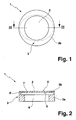
- FIG. 1 the structure of an adaptive mirror 1 of a laser processing machine, not shown per se known.
- Adaptive or deformable means within the meaning of the invention an aspherical deformation of the mirror plate membrane 2 , which can be specifically varied and adjusted.
- Such adaptive mirrors 1 can be used according to the invention for large beam deflection angles.
- the mirror 1 comprises, in addition to the mirror plate membrane 2, a membrane carrier 3 , which is essentially formed by a tubular extension 3a (cylinder) and a transition region 3b and constitutes a connection piece for mounting the mirror 1 on the laser processing machine.
- Pipe extension 3a, transition region 3b and mirror plate membrane 2 together form an integrally formed component in which the mirror plate membrane 2 is integrated into the membrane carrier 3, ie the mirror plate membrane 2 has a fixed mechanical clamping.
- the curvatures of the mirror plate membrane 2 are of a slight concave above plan, slightly convex adjustable.
- the mirror 1 can simultaneously to Focus adjustment and beam deflection of the laser beam in Processing head of the laser processing machine can be used.
- the back of the mirror plate membrane 2 can be pressurized.
- the pressurizable surface is produced by milling under the mirror plate diaphragm 2 or by milling of a recess 8 of the pipe socket 3a below the mirror plate diaphragm 2.
- the milled under training is the Fig. 2 can be seen.
- a first mirror interior (cavity) 6 with a circular cross section merges into a second mirror interior 7 with an elliptical cross section.
- the membrane carrier 3 can be flanged to other components of the laser processing machine, via which, for example, a cooling water supply into the mirror interior spaces 6 and 7 can take place.
- a pressurization of the membrane rear side 5 is brought about.
- the mirror interior 7 can be filled with cooling water or a fluid, so that the elliptical surface of the mirror plate membrane 2 can be pressurized in a targeted manner.
- the reflective surface 4 of Mirror plate membrane 2 may be formed or imprinted. It learns the mirror plate membrane 2 thickness deviations. This version is for Applications suitable for larger (convex and concave) Require curvatures.
- the mirror plate membrane 2 does not necessarily have just be trained, but by targeted changes in thickness can be given different curvatures.
- the reflective surface 4 of the mirror 1 a macroscopic, predetermined Have curvature ("focusing mirror"), so that a focus of the Laser beam is achieved.
- FIGS. 3 and 4 show, in the case of a mirror 11, an alternative for forming a mirror plate membrane 12 having an elliptical surface.
- An outwardly annular membrane carrier 13 is integrally connected to the mirror plate membrane 12 and defines inwardly a mirror plate membrane 12 having an elliptical surface.
- the laser beam is deflected at a reflecting mirror surface 14 .
- a membrane rear side 15 can be pressurized if a single mirror interior 16 is filled with cooling water.
Landscapes
- Physics & Mathematics (AREA)
- Optics & Photonics (AREA)
- Engineering & Computer Science (AREA)
- Plasma & Fusion (AREA)
- Mechanical Engineering (AREA)
- General Physics & Mathematics (AREA)
- Optical Elements Other Than Lenses (AREA)
- Laser Beam Processing (AREA)
- Mounting And Adjusting Of Optical Elements (AREA)
- Lasers (AREA)
- Electrical Discharge Machining, Electrochemical Machining, And Combined Machining (AREA)
Abstract
Description
- Fig. 1
- eine Ansicht auf die Unterseite eines ersten erfindungsgemäßen Spiegels einer Laserbearbeitungsmaschine;
- Fig. 2
- einen Schnitt des Spiegels längs einer Linie II-II nach Fig. 1;
- Fig. 3
- eine Ansicht auf die Unterseite eines zweiten erfindungsgemäßen Spiegels einer Laserbearbeitungsmaschine;
- Fig. 4
- einen Schnitt des Spiegels längs einer Linie IV-IV nach Fig. 3;
- Fig. 5
- eine Prinzipdarstellung einer Strahlführung einer Laserbearbeitungsmaschine nach dem Stand der Technik.
- 1
- Spiegel
- 2
- Spiegelplattenmembran
- 3
- Membranträger
- 3a
- Rohransatz
- 3b
- Übergangsbereich
- 4
- Spiegelfläche
- 5
- Membranrückseite
- 6
- Erster Spiegelinnenraum
- 7
- Zweiter Spiegelinnenraum
- 8
- Ausnehmung
- 11
- Spiegel
- 12
- Spiegelplattenmembran
- 13
- Membranträger
- 14
- Spiegelfläche
- 15
- Membranrückseite
- 16
- Spiegelinnenraum
- 17
- Laserstrahl
- 18
- Spiegel
- 19
- Spiegel
Claims (6)
- Spiegel (1; 11) einer Laserbearbeitungsmaschine mit einer über ihre Membranrückseite (5; 15) druckbeaufschlagbaren Spiegelplattenmembran (2; 12) und mit einem Membranträger (3; 13), dadurch gekennzeichnet, dass der Membranträger (3; 13) im Bereich der Membranrückseite (5; 15) eine druckbeaufschlagbare, annähernd elliptische oder annähernd rechteckige oder ovale Fläche der Membranrückseite (5; 15) begrenzt.
- Spiegel nach Anspruch 1, dadurch gekennzeichnet, dass der Membranträger (3) im Übergangsbereich zur Spiegelplattenmembran (2) eine Ausnehmung (8) aufweist.
- Spiegel nach Anspruch 1 oder 2, dadurch gekennzeichnet, dass die annähernd elliptische oder annähernd rechteckige oder ovale Fläche der Membranrückseite (5; 15) durch Kühlwasser oder ein Fluid druckbeaufschlagbar ist.
- Spiegel nach Anspruch 1 oder 2, dadurch gekennzeichnet, dass die annähernd elliptische oder annähernd rechteckige oder ovale Fläche der Membranrückseite (5; 15) durch einen Aktuator druckbeaufschlagbar ist.
- Spiegel nach einem der vorhergehenden Ansprüche, dadurch gekennzeichnet, dass der Membranträger (3; 13) einen Rohransatz mit kreisrundem Querschnitt umfasst.
- Spiegel nach einem der vorhergehenden Ansprüche, dadurch gekennzeichnet, dass die reflektierende Fläche (4) des Spiegels (1) eine vorgegebene Krümmung aufweist.
Priority Applications (5)
| Application Number | Priority Date | Filing Date | Title |
|---|---|---|---|
| EP02026664A EP1424584B1 (de) | 2002-11-29 | 2002-11-29 | Spiegel einer Laserbearbeitungsmaschine |
| AT02026664T ATE355543T1 (de) | 2002-11-29 | 2002-11-29 | Spiegel einer laserbearbeitungsmaschine |
| DE50209599T DE50209599D1 (de) | 2002-11-29 | 2002-11-29 | Spiegel einer Laserbearbeitungsmaschine |
| US10/722,362 US7102806B2 (en) | 2002-11-29 | 2003-11-26 | Pressure sensitive deformable mirror |
| JP2003400239A JP4603790B2 (ja) | 2002-11-29 | 2003-11-28 | レーザ加工機械のミラー |
Applications Claiming Priority (1)
| Application Number | Priority Date | Filing Date | Title |
|---|---|---|---|
| EP02026664A EP1424584B1 (de) | 2002-11-29 | 2002-11-29 | Spiegel einer Laserbearbeitungsmaschine |
Publications (2)
| Publication Number | Publication Date |
|---|---|
| EP1424584A1 true EP1424584A1 (de) | 2004-06-02 |
| EP1424584B1 EP1424584B1 (de) | 2007-02-28 |
Family
ID=32241312
Family Applications (1)
| Application Number | Title | Priority Date | Filing Date |
|---|---|---|---|
| EP02026664A Expired - Lifetime EP1424584B1 (de) | 2002-11-29 | 2002-11-29 | Spiegel einer Laserbearbeitungsmaschine |
Country Status (5)
| Country | Link |
|---|---|
| US (1) | US7102806B2 (de) |
| EP (1) | EP1424584B1 (de) |
| JP (1) | JP4603790B2 (de) |
| AT (1) | ATE355543T1 (de) |
| DE (1) | DE50209599D1 (de) |
Cited By (4)
| Publication number | Priority date | Publication date | Assignee | Title |
|---|---|---|---|---|
| WO2007079760A1 (de) * | 2005-12-23 | 2007-07-19 | Trumpf Werkzeugmaschinen Gmbh + Co. Kg | Scannerkopf und bearbeitungsmaschine damit |
| DE102013212685A1 (de) | 2013-06-28 | 2014-12-31 | Trumpf Laser- Und Systemtechnik Gmbh | Strahlbeeinflussungsoptik und Strahlformungssystem |
| DE102015215645A1 (de) | 2015-08-17 | 2017-02-23 | Trumpf Laser- Und Systemtechnik Gmbh | Vorrichtung und Verfahren zur Erwärmung eines Objekts und Vorrichtung zur Oberflächenbehandlung |
| DE112009000774B4 (de) * | 2008-04-04 | 2018-02-15 | Mitsubishi Electric Corporation | Laserprozessierungsvorrichtung beinhaltend eine Prozesssteuervorrichtung |
Families Citing this family (7)
| Publication number | Priority date | Publication date | Assignee | Title |
|---|---|---|---|---|
| JP4182034B2 (ja) * | 2004-08-05 | 2008-11-19 | ファナック株式会社 | 切断加工用レーザ装置 |
| DE202005006838U1 (de) * | 2005-04-29 | 2006-08-31 | Trumpf Werkzeugmaschinen Gmbh + Co. Kg | Optisches Modul zum Einbau in den Laser einer Laserbearbeitungsmaschine |
| US8243133B1 (en) * | 2008-06-28 | 2012-08-14 | Aoptix Technologies, Inc. | Scale-invariant, resolution-invariant iris imaging using reflection from the eye |
| JP2010040784A (ja) * | 2008-08-05 | 2010-02-18 | Fanuc Ltd | レーザ加工装置 |
| DE102013008647B4 (de) * | 2013-05-21 | 2019-02-21 | Lt-Ultra Precision Technology Gmbh | Laserbearbeitungsvorrichtung mit zwei adaptiven Spiegeln |
| US9360600B2 (en) * | 2013-11-20 | 2016-06-07 | Asml Netherlands B.V. | System and method for correcting the focus of a laser beam |
| CN114924407A (zh) * | 2022-06-10 | 2022-08-19 | 北京工业大学 | 激光扫描振镜系统 |
Citations (6)
| Publication number | Priority date | Publication date | Assignee | Title |
|---|---|---|---|---|
| DE3424068A1 (de) * | 1983-10-17 | 1985-05-02 | Canon K.K., Tokio/Tokyo | Optisches bauelement |
| US4932768A (en) * | 1989-07-25 | 1990-06-12 | Chromex, Inc. | Aspheric mirror produced by the elastic deformation of a spherical mirror |
| DE3900467A1 (de) * | 1989-01-10 | 1990-07-26 | Trumpf Lasertechnik Gmbh | Laserspiegelkopf |
| DE19628672A1 (de) * | 1996-07-16 | 1998-01-22 | Precitec Gmbh | Adaptiver Spiegel |
| DE10001900A1 (de) * | 2000-01-19 | 2001-08-16 | Diehl Munitionssysteme Gmbh | Deformierbarer Spiegel, insbesondere für eine Laserstrahl-Materialbearbeitungseinrichtung |
| DE10052249A1 (de) * | 2000-10-21 | 2002-04-25 | Lt Ultra Prec Technology Gmbh | Deformierbarer Spiegel, insbesondere adaptiver Spiegel |
Family Cites Families (6)
| Publication number | Priority date | Publication date | Assignee | Title |
|---|---|---|---|---|
| GB2183059B (en) | 1985-11-05 | 1989-09-27 | Michel Treisman | Suspension system for a flexible optical membrane |
| US5148324A (en) * | 1991-01-25 | 1992-09-15 | U.S. Philips Corp. | Mirror unit |
| JP3138613B2 (ja) * | 1995-05-24 | 2001-02-26 | 三菱電機株式会社 | レーザ加工装置 |
| JPH11202110A (ja) * | 1998-01-20 | 1999-07-30 | Nippon Steel Corp | 可変形反射鏡 |
| JP3854010B2 (ja) * | 1999-05-20 | 2006-12-06 | 株式会社アマダエンジニアリングセンター | 曲率可変ミラーの曲率調整装置 |
| US6425671B1 (en) * | 2000-04-13 | 2002-07-30 | Alan Adler | Optical mirror flexing structure and assembly |
-
2002
- 2002-11-29 DE DE50209599T patent/DE50209599D1/de not_active Expired - Lifetime
- 2002-11-29 EP EP02026664A patent/EP1424584B1/de not_active Expired - Lifetime
- 2002-11-29 AT AT02026664T patent/ATE355543T1/de not_active IP Right Cessation
-
2003
- 2003-11-26 US US10/722,362 patent/US7102806B2/en not_active Expired - Lifetime
- 2003-11-28 JP JP2003400239A patent/JP4603790B2/ja not_active Expired - Fee Related
Patent Citations (6)
| Publication number | Priority date | Publication date | Assignee | Title |
|---|---|---|---|---|
| DE3424068A1 (de) * | 1983-10-17 | 1985-05-02 | Canon K.K., Tokio/Tokyo | Optisches bauelement |
| DE3900467A1 (de) * | 1989-01-10 | 1990-07-26 | Trumpf Lasertechnik Gmbh | Laserspiegelkopf |
| US4932768A (en) * | 1989-07-25 | 1990-06-12 | Chromex, Inc. | Aspheric mirror produced by the elastic deformation of a spherical mirror |
| DE19628672A1 (de) * | 1996-07-16 | 1998-01-22 | Precitec Gmbh | Adaptiver Spiegel |
| DE10001900A1 (de) * | 2000-01-19 | 2001-08-16 | Diehl Munitionssysteme Gmbh | Deformierbarer Spiegel, insbesondere für eine Laserstrahl-Materialbearbeitungseinrichtung |
| DE10052249A1 (de) * | 2000-10-21 | 2002-04-25 | Lt Ultra Prec Technology Gmbh | Deformierbarer Spiegel, insbesondere adaptiver Spiegel |
Cited By (6)
| Publication number | Priority date | Publication date | Assignee | Title |
|---|---|---|---|---|
| WO2007079760A1 (de) * | 2005-12-23 | 2007-07-19 | Trumpf Werkzeugmaschinen Gmbh + Co. Kg | Scannerkopf und bearbeitungsmaschine damit |
| US7525708B2 (en) | 2005-12-23 | 2009-04-28 | Trumpf Werkzeugmaschinen Gmbh + Co. Kg | Scanner head for a laser machining device |
| CN101346208B (zh) * | 2005-12-23 | 2011-03-30 | 通快机床两合公司 | 扫描头和具有这种扫描头的加工机 |
| DE112009000774B4 (de) * | 2008-04-04 | 2018-02-15 | Mitsubishi Electric Corporation | Laserprozessierungsvorrichtung beinhaltend eine Prozesssteuervorrichtung |
| DE102013212685A1 (de) | 2013-06-28 | 2014-12-31 | Trumpf Laser- Und Systemtechnik Gmbh | Strahlbeeinflussungsoptik und Strahlformungssystem |
| DE102015215645A1 (de) | 2015-08-17 | 2017-02-23 | Trumpf Laser- Und Systemtechnik Gmbh | Vorrichtung und Verfahren zur Erwärmung eines Objekts und Vorrichtung zur Oberflächenbehandlung |
Also Published As
| Publication number | Publication date |
|---|---|
| US20050002078A1 (en) | 2005-01-06 |
| EP1424584B1 (de) | 2007-02-28 |
| JP2004181532A (ja) | 2004-07-02 |
| DE50209599D1 (de) | 2007-04-12 |
| JP4603790B2 (ja) | 2010-12-22 |
| ATE355543T1 (de) | 2006-03-15 |
| US7102806B2 (en) | 2006-09-05 |
Similar Documents
| Publication | Publication Date | Title |
|---|---|---|
| EP1424584B1 (de) | Spiegel einer Laserbearbeitungsmaschine | |
| DE202013006369U1 (de) | F-Theta-Objektiv | |
| DE102013008646B4 (de) | Adaptiver Spiegel für eine Laserbearbeitungsvorrichtung | |
| DE102013105425B3 (de) | Fotografisches Weitwinkelobjektiv mit Innenfokussierung | |
| DE10020914B4 (de) | Verfahren zur Berechnung einer Mehrzahl Brillenlinsen einer Brillenlinsenfamilie sowie Verfahren der Fertigung einer Brillenlinse einer Brillenlinsenfamilie | |
| DE102008035224B4 (de) | Laseroszillator mit einer Befestigungskonstruktion für ein optisches Element | |
| DE202011108359U1 (de) | Projektions-Lichtmodul für einen Kraftfahrzeugscheinwerfer | |
| DE102008044365A1 (de) | Optische Baugruppe und Projektionsbelichtungsanlage für die Halbleiterlithographie | |
| DE60202804T2 (de) | Torisches Werkzeug zum Polieren einer optischen Fläche einer atorischen Linse und Polierverfahren mit einem solchen Werkzeug | |
| DE102016211811B4 (de) | F-Theta-Objektiv und Scannervorrichtung damit | |
| DE102004050574A1 (de) | Vorrichtung zur Darstellung von optischen Informationen mittels eines virtuellen Bildes, insbesondere in einem Kraftfahrzeug | |
| DE202005015719U1 (de) | F/theta-Objektiv und Scannervorrichtung damit | |
| DE102010019491A1 (de) | Polierwerkzeug zur Bearbeitung von optischen Flächen, insbesondere Freiformflächen | |
| DE2843835A1 (de) | Binokulares beobachtungsgeraet | |
| DE102017209325B4 (de) | F-Theta-Objektiv mit zumindest einer ersten und einer zweiten optischen Baugruppe und eine Anordnung zur Lasermaterialbearbeitung mit einem F-Theta-Objektiv | |
| DE102019123239A1 (de) | Verfahren und Vorrichtung zum Trennen eines Werkstücks mittels eines Laserstrahls | |
| AT501203A1 (de) | Linse für einen lasergezündeten verbrennungsmotor | |
| DE102006003375A1 (de) | Gruppenweise korrigiertes Objektiv | |
| WO2020043552A1 (de) | Optisches system zur verwendung in einer unterwasserumgebung | |
| DE102004013673B4 (de) | Lagesicherung für Lagerschalen | |
| DE102015115313B4 (de) | Schleifwerkzeug und dessen Verwendung zur computergesteuerten Nachbearbeitung gefräster Freiformflächen | |
| DE19958331B4 (de) | Linse mit rückseitiger progressiver Brechkraftverteilung | |
| DE60312818T2 (de) | Progressive linse mit verminderter verzerrung | |
| DE102014106316B3 (de) | Objektiv mit einer lateral justierbaren Linse | |
| EP0520326A2 (de) | Spiegelobjektiv |
Legal Events
| Date | Code | Title | Description |
|---|---|---|---|
| PUAI | Public reference made under article 153(3) epc to a published international application that has entered the european phase |
Free format text: ORIGINAL CODE: 0009012 |
|
| AK | Designated contracting states |
Kind code of ref document: A1 Designated state(s): AT BE BG CH CY CZ DE DK EE ES FI FR GB GR IE IT LI LU MC NL PT SE SK TR |
|
| AX | Request for extension of the european patent |
Extension state: AL LT LV MK RO SI |
|
| 17P | Request for examination filed |
Effective date: 20041113 |
|
| 17Q | First examination report despatched |
Effective date: 20041220 |
|
| AKX | Designation fees paid |
Designated state(s): AT BE BG CH CY CZ DE DK EE ES FI FR GB GR IE IT LI LU MC NL PT SE SK TR |
|
| GRAP | Despatch of communication of intention to grant a patent |
Free format text: ORIGINAL CODE: EPIDOSNIGR1 |
|
| GRAS | Grant fee paid |
Free format text: ORIGINAL CODE: EPIDOSNIGR3 |
|
| GRAA | (expected) grant |
Free format text: ORIGINAL CODE: 0009210 |
|
| AK | Designated contracting states |
Kind code of ref document: B1 Designated state(s): AT BE BG CH CY CZ DE DK EE ES FI FR GB GR IE IT LI LU MC NL PT SE SK TR |
|
| PG25 | Lapsed in a contracting state [announced via postgrant information from national office to epo] |
Ref country code: NL Free format text: LAPSE BECAUSE OF FAILURE TO SUBMIT A TRANSLATION OF THE DESCRIPTION OR TO PAY THE FEE WITHIN THE PRESCRIBED TIME-LIMIT Effective date: 20070228 Ref country code: IE Free format text: LAPSE BECAUSE OF FAILURE TO SUBMIT A TRANSLATION OF THE DESCRIPTION OR TO PAY THE FEE WITHIN THE PRESCRIBED TIME-LIMIT Effective date: 20070228 Ref country code: FI Free format text: LAPSE BECAUSE OF FAILURE TO SUBMIT A TRANSLATION OF THE DESCRIPTION OR TO PAY THE FEE WITHIN THE PRESCRIBED TIME-LIMIT Effective date: 20070228 Ref country code: DK Free format text: LAPSE BECAUSE OF FAILURE TO SUBMIT A TRANSLATION OF THE DESCRIPTION OR TO PAY THE FEE WITHIN THE PRESCRIBED TIME-LIMIT Effective date: 20070228 |
|
| REG | Reference to a national code |
Ref country code: GB Ref legal event code: FG4D Free format text: NOT ENGLISH |
|
| REG | Reference to a national code |
Ref country code: CH Ref legal event code: EP |
|
| REF | Corresponds to: |
Ref document number: 50209599 Country of ref document: DE Date of ref document: 20070412 Kind code of ref document: P |
|
| REG | Reference to a national code |
Ref country code: IE Ref legal event code: FG4D Free format text: LANGUAGE OF EP DOCUMENT: GERMAN |
|
| GBT | Gb: translation of ep patent filed (gb section 77(6)(a)/1977) |
Effective date: 20070426 |
|
| PG25 | Lapsed in a contracting state [announced via postgrant information from national office to epo] |
Ref country code: BG Free format text: LAPSE BECAUSE OF THE APPLICANT RENOUNCES Effective date: 20070529 |
|
| PG25 | Lapsed in a contracting state [announced via postgrant information from national office to epo] |
Ref country code: SE Free format text: LAPSE BECAUSE OF FAILURE TO SUBMIT A TRANSLATION OF THE DESCRIPTION OR TO PAY THE FEE WITHIN THE PRESCRIBED TIME-LIMIT Effective date: 20070531 |
|
| PG25 | Lapsed in a contracting state [announced via postgrant information from national office to epo] |
Ref country code: ES Free format text: LAPSE BECAUSE OF FAILURE TO SUBMIT A TRANSLATION OF THE DESCRIPTION OR TO PAY THE FEE WITHIN THE PRESCRIBED TIME-LIMIT Effective date: 20070608 |
|
| PG25 | Lapsed in a contracting state [announced via postgrant information from national office to epo] |
Ref country code: PT Free format text: LAPSE BECAUSE OF FAILURE TO SUBMIT A TRANSLATION OF THE DESCRIPTION OR TO PAY THE FEE WITHIN THE PRESCRIBED TIME-LIMIT Effective date: 20070730 |
|
| NLV1 | Nl: lapsed or annulled due to failure to fulfill the requirements of art. 29p and 29m of the patents act | ||
| ET | Fr: translation filed | ||
| REG | Reference to a national code |
Ref country code: IE Ref legal event code: FD4D |
|
| PG25 | Lapsed in a contracting state [announced via postgrant information from national office to epo] |
Ref country code: SK Free format text: LAPSE BECAUSE OF FAILURE TO SUBMIT A TRANSLATION OF THE DESCRIPTION OR TO PAY THE FEE WITHIN THE PRESCRIBED TIME-LIMIT Effective date: 20070228 |
|
| PG25 | Lapsed in a contracting state [announced via postgrant information from national office to epo] |
Ref country code: CZ Free format text: LAPSE BECAUSE OF FAILURE TO SUBMIT A TRANSLATION OF THE DESCRIPTION OR TO PAY THE FEE WITHIN THE PRESCRIBED TIME-LIMIT Effective date: 20070228 |
|
| PLBE | No opposition filed within time limit |
Free format text: ORIGINAL CODE: 0009261 |
|
| STAA | Information on the status of an ep patent application or granted ep patent |
Free format text: STATUS: NO OPPOSITION FILED WITHIN TIME LIMIT |
|
| 26N | No opposition filed |
Effective date: 20071129 |
|
| PG25 | Lapsed in a contracting state [announced via postgrant information from national office to epo] |
Ref country code: GR Free format text: LAPSE BECAUSE OF FAILURE TO SUBMIT A TRANSLATION OF THE DESCRIPTION OR TO PAY THE FEE WITHIN THE PRESCRIBED TIME-LIMIT Effective date: 20070529 |
|
| BERE | Be: lapsed |
Owner name: TRUMPF WERKZEUGMASCHINEN G.M.B.H. + CO. KG Effective date: 20071130 |
|
| PG25 | Lapsed in a contracting state [announced via postgrant information from national office to epo] |
Ref country code: MC Free format text: LAPSE BECAUSE OF NON-PAYMENT OF DUE FEES Effective date: 20071130 |
|
| PG25 | Lapsed in a contracting state [announced via postgrant information from national office to epo] |
Ref country code: BE Free format text: LAPSE BECAUSE OF NON-PAYMENT OF DUE FEES Effective date: 20071130 |
|
| PG25 | Lapsed in a contracting state [announced via postgrant information from national office to epo] |
Ref country code: EE Free format text: LAPSE BECAUSE OF FAILURE TO SUBMIT A TRANSLATION OF THE DESCRIPTION OR TO PAY THE FEE WITHIN THE PRESCRIBED TIME-LIMIT Effective date: 20070228 |
|
| PGFP | Annual fee paid to national office [announced via postgrant information from national office to epo] |
Ref country code: AT Payment date: 20081120 Year of fee payment: 7 |
|
| PG25 | Lapsed in a contracting state [announced via postgrant information from national office to epo] |
Ref country code: CY Free format text: LAPSE BECAUSE OF FAILURE TO SUBMIT A TRANSLATION OF THE DESCRIPTION OR TO PAY THE FEE WITHIN THE PRESCRIBED TIME-LIMIT Effective date: 20070228 |
|
| PG25 | Lapsed in a contracting state [announced via postgrant information from national office to epo] |
Ref country code: LU Free format text: LAPSE BECAUSE OF NON-PAYMENT OF DUE FEES Effective date: 20071129 |
|
| PG25 | Lapsed in a contracting state [announced via postgrant information from national office to epo] |
Ref country code: TR Free format text: LAPSE BECAUSE OF FAILURE TO SUBMIT A TRANSLATION OF THE DESCRIPTION OR TO PAY THE FEE WITHIN THE PRESCRIBED TIME-LIMIT Effective date: 20070228 |
|
| PG25 | Lapsed in a contracting state [announced via postgrant information from national office to epo] |
Ref country code: AT Free format text: LAPSE BECAUSE OF NON-PAYMENT OF DUE FEES Effective date: 20091129 |
|
| REG | Reference to a national code |
Ref country code: FR Ref legal event code: PLFP Year of fee payment: 14 |
|
| REG | Reference to a national code |
Ref country code: FR Ref legal event code: PLFP Year of fee payment: 15 |
|
| REG | Reference to a national code |
Ref country code: FR Ref legal event code: PLFP Year of fee payment: 16 |
|
| PGFP | Annual fee paid to national office [announced via postgrant information from national office to epo] |
Ref country code: FR Payment date: 20191120 Year of fee payment: 18 |
|
| PGFP | Annual fee paid to national office [announced via postgrant information from national office to epo] |
Ref country code: GB Payment date: 20191120 Year of fee payment: 18 |
|
| GBPC | Gb: european patent ceased through non-payment of renewal fee |
Effective date: 20201129 |
|
| PG25 | Lapsed in a contracting state [announced via postgrant information from national office to epo] |
Ref country code: FR Free format text: LAPSE BECAUSE OF NON-PAYMENT OF DUE FEES Effective date: 20201130 |
|
| PG25 | Lapsed in a contracting state [announced via postgrant information from national office to epo] |
Ref country code: GB Free format text: LAPSE BECAUSE OF NON-PAYMENT OF DUE FEES Effective date: 20201129 |
|
| PGFP | Annual fee paid to national office [announced via postgrant information from national office to epo] |
Ref country code: DE Payment date: 20211118 Year of fee payment: 20 |
|
| PGFP | Annual fee paid to national office [announced via postgrant information from national office to epo] |
Ref country code: IT Payment date: 20211119 Year of fee payment: 20 Ref country code: CH Payment date: 20211119 Year of fee payment: 20 |
|
| REG | Reference to a national code |
Ref country code: DE Ref legal event code: R071 Ref document number: 50209599 Country of ref document: DE |
|
| REG | Reference to a national code |
Ref country code: CH Ref legal event code: PL |