EP1424474A1 - Method of controlling internal combustion engine - Google Patents
Method of controlling internal combustion engine Download PDFInfo
- Publication number
- EP1424474A1 EP1424474A1 EP02762997A EP02762997A EP1424474A1 EP 1424474 A1 EP1424474 A1 EP 1424474A1 EP 02762997 A EP02762997 A EP 02762997A EP 02762997 A EP02762997 A EP 02762997A EP 1424474 A1 EP1424474 A1 EP 1424474A1
- Authority
- EP
- European Patent Office
- Prior art keywords
- exhaust
- air supply
- cam
- exhaust valve
- stroke
- Prior art date
- Legal status (The legal status is an assumption and is not a legal conclusion. Google has not performed a legal analysis and makes no representation as to the accuracy of the status listed.)
- Withdrawn
Links
Images


Classifications
-
- F—MECHANICAL ENGINEERING; LIGHTING; HEATING; WEAPONS; BLASTING
- F02—COMBUSTION ENGINES; HOT-GAS OR COMBUSTION-PRODUCT ENGINE PLANTS
- F02D—CONTROLLING COMBUSTION ENGINES
- F02D13/00—Controlling the engine output power by varying inlet or exhaust valve operating characteristics, e.g. timing
- F02D13/02—Controlling the engine output power by varying inlet or exhaust valve operating characteristics, e.g. timing during engine operation
- F02D13/0269—Controlling the valves to perform a Miller-Atkinson cycle
-
- F—MECHANICAL ENGINEERING; LIGHTING; HEATING; WEAPONS; BLASTING
- F02—COMBUSTION ENGINES; HOT-GAS OR COMBUSTION-PRODUCT ENGINE PLANTS
- F02D—CONTROLLING COMBUSTION ENGINES
- F02D13/00—Controlling the engine output power by varying inlet or exhaust valve operating characteristics, e.g. timing
- F02D13/02—Controlling the engine output power by varying inlet or exhaust valve operating characteristics, e.g. timing during engine operation
-
- F—MECHANICAL ENGINEERING; LIGHTING; HEATING; WEAPONS; BLASTING
- F01—MACHINES OR ENGINES IN GENERAL; ENGINE PLANTS IN GENERAL; STEAM ENGINES
- F01L—CYCLICALLY OPERATING VALVES FOR MACHINES OR ENGINES
- F01L1/00—Valve-gear or valve arrangements, e.g. lift-valve gear
- F01L1/02—Valve drive
- F01L1/04—Valve drive by means of cams, camshafts, cam discs, eccentrics or the like
- F01L1/08—Shape of cams
-
- F—MECHANICAL ENGINEERING; LIGHTING; HEATING; WEAPONS; BLASTING
- F01—MACHINES OR ENGINES IN GENERAL; ENGINE PLANTS IN GENERAL; STEAM ENGINES
- F01L—CYCLICALLY OPERATING VALVES FOR MACHINES OR ENGINES
- F01L13/00—Modifications of valve-gear to facilitate reversing, braking, starting, changing compression ratio, or other specific operations
- F01L13/0015—Modifications of valve-gear to facilitate reversing, braking, starting, changing compression ratio, or other specific operations for optimising engine performances by modifying valve lift according to various working parameters, e.g. rotational speed, load, torque
-
- F—MECHANICAL ENGINEERING; LIGHTING; HEATING; WEAPONS; BLASTING
- F02—COMBUSTION ENGINES; HOT-GAS OR COMBUSTION-PRODUCT ENGINE PLANTS
- F02D—CONTROLLING COMBUSTION ENGINES
- F02D15/00—Varying compression ratio
-
- F—MECHANICAL ENGINEERING; LIGHTING; HEATING; WEAPONS; BLASTING
- F01—MACHINES OR ENGINES IN GENERAL; ENGINE PLANTS IN GENERAL; STEAM ENGINES
- F01L—CYCLICALLY OPERATING VALVES FOR MACHINES OR ENGINES
- F01L2800/00—Methods of operation using a variable valve timing mechanism
-
- F—MECHANICAL ENGINEERING; LIGHTING; HEATING; WEAPONS; BLASTING
- F02—COMBUSTION ENGINES; HOT-GAS OR COMBUSTION-PRODUCT ENGINE PLANTS
- F02D—CONTROLLING COMBUSTION ENGINES
- F02D41/00—Electrical control of supply of combustible mixture or its constituents
- F02D41/0002—Controlling intake air
- F02D2041/001—Controlling intake air for engines with variable valve actuation
-
- F—MECHANICAL ENGINEERING; LIGHTING; HEATING; WEAPONS; BLASTING
- F02—COMBUSTION ENGINES; HOT-GAS OR COMBUSTION-PRODUCT ENGINE PLANTS
- F02D—CONTROLLING COMBUSTION ENGINES
- F02D2700/00—Mechanical control of speed or power of a single cylinder piston engine
- F02D2700/03—Controlling by changing the compression ratio
- F02D2700/035—Controlling by changing the compression ratio without modifying the volume of the compression space, e.g. by changing the valve timing
-
- Y—GENERAL TAGGING OF NEW TECHNOLOGICAL DEVELOPMENTS; GENERAL TAGGING OF CROSS-SECTIONAL TECHNOLOGIES SPANNING OVER SEVERAL SECTIONS OF THE IPC; TECHNICAL SUBJECTS COVERED BY FORMER USPC CROSS-REFERENCE ART COLLECTIONS [XRACs] AND DIGESTS
- Y02—TECHNOLOGIES OR APPLICATIONS FOR MITIGATION OR ADAPTATION AGAINST CLIMATE CHANGE
- Y02T—CLIMATE CHANGE MITIGATION TECHNOLOGIES RELATED TO TRANSPORTATION
- Y02T10/00—Road transport of goods or passengers
- Y02T10/10—Internal combustion engine [ICE] based vehicles
- Y02T10/12—Improving ICE efficiencies
Definitions
- the present invention relates to a control method of an internal combustion engine, and more particularly to a control of opening and closing a valve in an internal combustion engine provided with a supercharger.
- This method corresponds to a method of increasing a maximum cylinder internal pressure so as to improve a heat efficiency, by making a compression ratio high and making a supercharging high.
- Fig. 23A shows an air supply stroke
- Fig. 23B shows a first stage of a compression stroke
- Fig. 23C shows a later stage of the compression stroke.
- a compression start time can be delayed by setting an air supply valve 1 in an open state until the compression stroke first stage in which a piston 8 is ascended, and closing the air supply valve 1 at a later time than a normal time, as shown in Fig. 23B, at the same time of increasing the compression ratio of the engine, whereby it is possible to reduce an effective compression ratio and it is possible to obtain a large expansion ratio while restricting an excessive increase of the cylinder internal pressure.
- FIG. 24 shows a change of an air supply valve lift in this method.
- the air supply valve lift shown by a solid line corresponds to a case of the normal cycle, and an air supply discharging period is secured till closely a middle of the compression stroke, by changing the air supply valve lift in the normal cycle to an air supply valve lift shape of the delayed closing as shown by a broken line.
- Fig. 25 shows an exhaust valve opening period and an air supply valve opening period of the internal combustion engine formed as the Atkinson cycle as shown in Figs. 23A, 23B, 23C and 24, a range (a crank angle) denoted by reference symbol OL is an overlap period between the exhaust valve opening period and the air supply valve opening period, and a crank angle range 82 is an air supply discharging period secured by the air supply valve delayed closing.
- a range (a crank angle) denoted by reference symbol OL is an overlap period between the exhaust valve opening period and the air supply valve opening period
- a crank angle range 82 is an air supply discharging period secured by the air supply valve delayed closing.
- Fig. 26 is an Atkinson cycle indicator diagram in the internal combustion engine in Figs. 23A to 25, a compression work load corresponding to a hatched area is reduced in comparison with the normal compression stroke shown by a broken line, by setting the air supply vale closing time SC later than the normal one in the compression stroke first stage.
- reference symbol EO denotes an exhaust valve opening time
- reference symbol SO denotes an air supply valve opening time
- reference symbol EC denotes an exhaust vale closing time.
- Fig. 27A shows an air supply stroke
- Fig. 27B shows an air supply stroke later stage
- Fig. 27C shows a compression stroke.
- This method is a method of achieving the Atkinson cycle by reducing an air supply amount supplied within the combustion chamber 3 by closing the air supply valve 1, and making the effective compression ratio small by reducing the compression stroke, in the air supply stroke later stage in which the piston 8 descends as shown in Fig. 27B.
- Fig. 28 shows an exhaust valve opening period and an air supply valve opening period in the internal combustion engine shown in Figs. 27A, 27B and 27C.
- Reference symbol OL denotes an overlap period between the exhaust valve opening period and the air supply valve opening period
- a crank angle ⁇ 3 is a crank angle (an angle of lead) between an air supply valve closing period and an air supply bottom dead center BDC.
- the air supply valve 1 is early closed the crank angle ⁇ 3 before the air supply bottom dead center BDC.
- Fig. 29 is an Atkinson cycle indicator diagram in the internal combustion engine shown in Figs. 27A, 27B, 27C and 28, a compression work load corresponding to a hatched area is reduced in comparison with the normal compression stroke shown by a broken line, by quickening the air supply vale closing time SC to the air supply stroke later stage, whereby a gas exchange work load is reduced.
- the closing time of the air supply valve is delayed for the purpose of delaying the compression starting time, however, a shape of an air supply cam is limited to a valve lift shape as shown by a broken line in Fig. 24 in view of a design of the air supply cam shape, the air supply valve is in a state of being largely open near the compression bottom dead center BDC, and a large amount of air is flown out. The waster outflow of the supply air causes a reduction of output.
- an air supply manifold pressure is higher than an exhaust manifold pressure except the period exposed to the influence of the exhaust gas in the other cylinders.
- an ascending work load of the piston becomes high, the piston is hard to ascend, and the loss work is increased.
- the lift period of the air supply valve is shortened, the lift amount of the air supply valve is limited geometrically at a time of designing the cam, so that the flow of the supply air from the air supply port to the combustion chamber is limited, and it is hard to secure a sufficient air supply amount, thereby causing a reduction of output.
- the air supply lift amount is limited in view of the cam design, in accordance with the shortened air supply period, the air supply amount is widely reduced, so that it is unavoidable to use a strong supercharger in order to secure the same air supply amount as the normal one.
- the air supply lift amount is small even by increasing the supercharged pressure, the air supply amount is not increased so much, so that thesupercharger efficiency is lowered in the same manner as that of the air supply valve delayed closing method, and comes close to the surging line B4 of the supercharger as shown by the position B2 in Fig. 12. Accordingly, there is a risk that the surging is generated.
- the present invention provides a method of controlling an internal combustion engine for intending an Atkinson cycle of a combustion cycle by delaying a compression starting time with utilizing an exhaust valve, in place of contriving a closing time of the air supply valve, and in accordance with the invention on the basis of a first aspect, there is provided a method of controlling an internal combustion engine, wherein an effective compression ratio is decreased by temporarily opening an exhaust valve in a compression stroke first stage.
- an expansion ratio is set higher (in a range from 15 to 20) than a conventional engine, and an effective compression ratio is optionally changed within a range from 0.5 to 0.9 times of the expansion ratio.
- a method of controlling an internal combustion engine as recited in the first or second aspect wherein an exhaust valve is not temporarily opened in a compression stroke first stage, at a time of starting or driving under a low load.
- a method of controlling an internal combustion engine as recited in the first to third aspect wherein the internal combustion engine is provided with a first exhaust cam having only a cam crest for an exhaust stroke, and a second exhaust cam having the cam crest for the exhaust stroke and a cam crest for re-opening the exhaust valve in the compression stroke first stage, and both the exhaust cams are used so as to be freely switched.
- a method of controlling an internal combustion engine as recited in the first to fourth aspect wherein the internal combustion engine is provided with a first exhaust cam having only a cam crest for an exhaust stroke, and an auxiliary exhaust cam having only a cam crest for re-opening the exhaust valve in the compression stroke first stage, and the method freely switches a single drive by means of the first exhaust cam, and a parallel drive by means of the first exhaust cam and the auxiliary exhaust cam.
- the Atkinson cycle is achieved by temporarily re-opening the exhaust valve in the compression stroke first stage so as to delay the compression starting time and make the effective compression ratio small, without delaying and quickening the closing time of the air supply valve, as is different from the conventional Atkinson cycle, it is possible to achieve a high expansion ratio while restricting the increase of the maximum cylinder internal pressure, and achieve an improvement of the heat efficiency, and the following effect can be obtained.
- Figs. 1A to 1C show a stroke change within a cylinder in the case that the present invention is applied to a direct injection type multiple cylinder diesel engine with supercharger.
- an air supply stroke shown in Fig. 1A since an air supply valve 1 is open, a supply air pressurized by the supercharger is supplied from an air supply port 2 into a combustion chamber 3.
- a compression stroke first stage of a piston ascending process shown in Fig. 1B the air supply valve 1 is closed and an exhaust valve 5 is temporarily re - opened, thereby evacuating a compressed pressure within the combustion chamber 3 from an exhaust port 6.
- the exhaust valve 5 for re-opening mentioned above is closed, and the supply air is substantially compressed.
- a compression start time is delayed by temporarily re-opening the exhaust valve 5 in the compression stroke first stage, thereby lowering an effective compression ratio and preventing a maximum cylinder internal pressure from being excessively increased.
- Fig. 2 shows an exhaust valve lift at a time of re-opening the exhaust valve in Fig. 1B together with an air supply valve lift.
- a shape of the air supply valve lift is the same as the normal air supply valve lift which is neither the delayed closing nor the early closing, and is in a slightly open state at a compression bottom dead center BDC.
- the exhaust valve at the re-opening time is structured such as to start lifting (opening) little by little from the compression bottom dead center BDC, start closing little by little after maintaining a fixed amount open state for a fixed period, and close in the middle of the compression stroke.
- This exhaust valve re-opening period corresponds to a supply air discharging period for discharging the supply air to the exhaust side.
- Fig. 3 shows a relation among the exhaust valve opening period, the air supply valve opening period and the exhaust valve re-opening period.
- the exhaust valve opening period is from a later stage of an explosion stroke to an early stage of the air supply stroke via the exhaust stroke
- the air supply valve opening period is from a final stage of the exhaust stroke to an early stage of the compression stroke via the air supply stroke
- an overlap period OL between the air supply valve opening period and the exhaust valve opening period exists in the vicinity of an exhaust gas top dead center (a supply air top dead center) TDC.
- the exhaust valve re-opening period (the supply air discharging period) is from the air supply bottom dead center BDC to about a middle of the compression stroke, as described in Fig. 2.
- Fig. 4 shows a relation among the exhaust valve lift, an exhaust manifold pressure, an air supply manifold pressure and a cylinder internal pressure at an exhaust valve re-opening time.
- the exhaust manifold pressure is temporarily higher than the air supply manifold pressure, however, the air supply manifold pressure pressurized by the supercharger is basically higher than the exhaust manifold pressure, and in the embodiment, the re-opening period (the supply air discharging period) of the exhaust valve is positioned within the period in which the air supply manifold pressure is higher than the exhaust manifold pressure.
- a piston ascending work such as a case of a supply air delayed closing type Atkinson cycle is reduced by temporarily re-opening the exhaust valve so as to discharge a part of the supply air to the exhaust port, in a period in which the exhaust manifold pressure is lower than the air supply manifold pressure, in the compression stroke first stage, as mentioned above.
- Fig. 11 is an indicator diagram showing a summary of a well-known theoretical Atkinson cycle (output cycle). A description will be briefly given of a concept of the Atkinson cycle by utilizing Fig. 11.
- Reference symbol V denotes a total volume
- reference symbol V1 denotes a volume of an adiabatic compression starting time A1
- reference symbol V2 denotes a volume of an adiabatic compression finishing time A2
- reference symbol V4 denotes a volume of an adiabatic expansion starting time A4
- reference symbol V6 denotes a volume of an adiabatic expansion finishing time (an exhaust valve opening time)
- A5 denotes a heating amount of an isovolumetric heating period (A2 ⁇ A3)
- reference symbol Qp denotes a heating amount of an isobaric(or isotacitc) heating period (A3 ⁇ A4)
- reference symbol Q1v denotes a heat dissipation amount of an isovolumetric heat dissipating
- reference symbol ⁇ is a politropic exponent
- reference symbol R is a gas constant
- reference symbol Cv is an isovolumic specific heat
- reference symbol Cp is an isopiestic specific heat
- ⁇ th 1 - (Q1v + Q1p)/(Qv + Qp)
- the theoretical heat efficiency ⁇ th is expressed by the formula (2) by introducing the relations of the amount of heat and the like and the following relations to the formula (1) of the heat efficiency.
- the present invention set preferably such that in the formula (2), the respective ratios are within the following ranges: EO volume ratio ⁇ is 0.8 to 0.95, effective compression ratio/expansion ratio ⁇ is 0.5 to 0.9, and apparent compression ratio ⁇ is 15 to 20.
- Figs. 5 and 6 show an example of an exhaust cam structure for re-opening the exhaust valve in the compression stroke first stage.
- a cam crest 12 for an exhaust stroke and a cam crest 13 for re-opening are formed in the same exhaust cam 11.
- Figs. 7 and 8 show another example of the exhaust cam structure for carrying out the exhaust valve re-opening.
- This example is provided with a first exhaust cam 21 having only the cam crest 12 for the exhaust stroke, and a second cam 22 having the cam crest 12 for the exhaust stroke and the cam crest 13 for re-opening, and both the exhaust cams 21 and 22 are used so as to be freely switched.
- the compression ratio high, so that the first exhaust cam 21 is utilized.
- the exhaust valve is re - opened in the compression stroke first stage by utilizing the second exhaust cam 22, thereby making the Atkinson cycle.
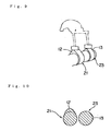
- Figs. 9 and 10 show the other example of the exhaust cam structure.
- This example is provided with the first exhaust cam 21 having only the cam crest 12 for the exhaust stroke, and an auxiliary exhaust cam 23 having only the cam crest 13 for re-opening, and the cams are used by switching between a simultaneous and parallel use of both the exhaust cams 21 and 23, and an independent use of the first exhaust cam 21.
- the compression ratio high, so that only the first exhaust cam 21 is independently used.
- the first exhaust cam 21 and the auxiliary exhaust cam 23 are used simultaneously and in parallel, and the exhaust valve is re - opened in the compression stroke first stage, thereby making the Atkinson cycle.
- Fig. 12 is an indicator diagram of the combustion cycle in the case of increasing the engine compression ratio, that is, the expansion ratio, and temporarily re-opening the exhaust valve in the compression stroke first stage.
- Reference symbol EO corresponds to an exhaust valve opening time
- reference symbol SO corresponds to an air supply valve opening time
- reference symbol EC corresponds to an exhaust valve closing time
- reference symbol SC corresponds to an air supply valve closing time, which are shown by a black circle.
- reference symbol REO corresponds to a start time of an exhaust valve re-opening
- reference symbol REC corresponds to a closing time (finishing time) of an exhaust valve re-opening, which are shown by a white circle.
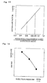
- Fig. 13 is a graph showing a relation between the effective compression ratio/expansion ratio and an excess air factor.
- the effective compression ratio/expansion ratio is approximately 1.
- the heat efficiency is improved by making the effective compression ratio/expansion ratio ⁇ small to a level within a range from 0.5 to 0.9 on the basis of the exhaust valve re-opening.
- the excess air factor is lowered in accordance with a degree that the effective compression ratio/expansion ratio is smaller than 1, the smoke is easily generated.
- the combustion injection pressure is made higher than the normal one, whereby the smoke is prevented from being generated.
- Fig. 15 shows a relation between a specific fuel consumption and a maximum cylinder internal pressure.
- a black circle position 1 ⁇ corresponds to the case of the normal cycle to which the Atkinson cycle is not introduced
- a black triangle position 5 ⁇ corresponds to a state in which the OL period is shortened and the supply air pressure is increased at the same time when the Atkinson cycle is introduced in accordance with the present invention.
- the position 5 ⁇ it is possible to widely lower the specific fuel consumption in comparison with the position 1 ⁇ , and it is possible to restrict the increase of the maximum cylinder internal pressure to an allowable level in a point of a strength or the like.
- a white square position 2 ⁇ and a white triangular position 3 ⁇ correspond to a conventional approach for improving the heat efficiency.
- the position runs from the position 1 ⁇ to the position 2 ⁇ along an arrow G1 by increasing the compression ratio and shortening the OL period, and further runs to the position 3 ⁇ along an arrow G3 by increasing the supply air pressure.
- the maximum cylinder internal pressure is increased to an allowable level in a point of the strength or the like, however, the specific fuel consumption is hardly lowered.
- the position 3 ⁇ the specific fuel consumption is widely lowered, however, the maximum cylinder internal pressure is excessively increased to a level in which a lack of strength is generated.
- a black square position 4 ⁇ corresponds to a state in which the Atkinson cycle is introduced from the position 1 ⁇ in accordance with the present invention and the OL period is shortened.
- the cylinder internal pressure is lowered to the same level as that of the normal cycle in the position 1 ⁇ , in comparison with the position 2 ⁇ in the conventional example, as shown by an arrow G2, and the specific fuel consumption is lowered in comparison with the position 2 ⁇ .
- the position runs to the position 5 ⁇ by making the supercharged pressure higher from the state in the position 4 ⁇ mentioned above, however, the specific fuel consumption is widely lowered as shown by an arrow G5, and the increase of the cylinder internal pressure can be restricted to the increase about the position 2 ⁇ mentioned above.
- the position also runs to the position 5 ⁇ as shown by an arrow G4, by introducing the Atkinson cycle in accordance with the present invention from the position 3 ⁇ .
- Fig. 16 is a graph showing a relation between the specific fuel consumption and the NOx.
- a black circle position 1 ⁇ corresponds to the case of the normal cycle which does not employ the Atkinson cycle
- a black square position 2 ⁇ corresponds to the case to which the Atkinson cycle is introduced in accordance with the present invention without changing the supercharged pressure from the position 1 ⁇ mentioned above.
- the NOx is reduced, however, the specific fuel consumption is a little increased.
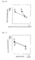
- Fig. 17 is a graph showing a relation between a smoke index and the NOx.
- Positions 1 ⁇ , 2 ⁇ and 3 ⁇ have the corresponding conditions to those in Fig. 16.
- the position 2 ⁇ corresponds to the case to which the Atkinson cycle is introduced without changing the supercharged pressure from the position 1 ⁇ corresponding to the normal cycle. In this position, the NOx is reduced, however, the smoke is increased. On the contrary, it is possible to restrict the NOx and the smoke to the same level as those of the actual position 1 ⁇ as in the position 3 ⁇ , by increasing the supply air pressure.
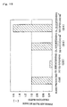
- Fig. 18 is an index of a working state of a supercharger compressor.
- Fig. 18 is a graph showing a supply air pressure ratio by a vertical axis and a compressor efficiency and a surging line with respect to a supply air flow rate by a horizontal axis.
- reference symbol B1 shows a case of the normal cycle to which the Atkinson cycle is not introduced
- reference symbol B2 shows a case that the Atkinson cycle is formed by the air supply valve delayed closing or the air supply valve early closing
- reference symbol B3 shows a case that the Atkinson cycle is formed by the re-opening of the exhaust valve in accordance with the present invention
- reference symbol B4 shows a surging line of the supercharger.
- Fig. 19 is a graph showing a relation between the overlap period (the period OL in Fig. 3) between the exhaust valve opening period and the air supply valve opening period, and a fresh air blow by rate.
- a mass-produced cam in a graph D1 corresponds to a case of the normal cycle which is not formed as the Atkinson cycle, and a fresh air blow by rate in this case is set to 1.
- the overlap period OL In the case that the overlap period OL is long, an atrophied state is formed from an air supply valve opening period SO to an exhaust valve closing period EC as shown in Fig. 20, a hatched area becomes small, and a loss of heat efficiency is generated.
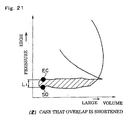
- the overlap period OL is simply shortened, it is possible to secure a rising edge L from the air supply valve opening period SO to the exhaust valve closing period EC as shown in Fig. 21, whereby it is possible to secure the hatched area large, and the heat efficiency is improved, however, the fresh air blow by rate is widely reduced as shown by a graph D2 in Fig. 19, and the exhaust gas temperature becomes too high.
- Fig. 22 shows a relation between a cylinder residual gas rate and the overlap period OL.
- the overlap period OL is shortened, the cylinder residual gas rate is increased, whereby it is possible to achieve the internal EGR effect and it is possible to intend to reduce the NOx.
- the present invention can be also utilized in gas and gasoline direct injection type internal combustion engines.
Landscapes
- Engineering & Computer Science (AREA)
- Mechanical Engineering (AREA)
- General Engineering & Computer Science (AREA)
- Chemical & Material Sciences (AREA)
- Combustion & Propulsion (AREA)
- Output Control And Ontrol Of Special Type Engine (AREA)
- Valve Device For Special Equipments (AREA)
- Valve-Gear Or Valve Arrangements (AREA)
Abstract
The invention provides a control method of intending to improve a
heat efficiency by an Atkinson cycle, improve a charging efficiency, improve
an efficiency of a supercharger and increase a freedom of cam design. In
particular, the invention relates to a control method of opening and closing a
valve in an internal combustion engine with supercharger. An effective
compression ratio is decreased by temporarily re-opening an exhaust valve
in a compression stroke first stage, whereby a heat efficiency is improved
without excessively increasing a cylinder internal pressure. Preferably, an
exhaust valve re-opening time is set such that the effective compression
ratio/expansion ratio is within a range from 0.5 to 0.9. Further, an exhaust
valve is not temporarily opened in a compression stroke first stage, at a time
of starting or driving under a low load, and the Atkinson cycle in accordance
with the re-opening of the exhaust valve is achieved at a time of driving
under a high load.
Description
The present invention relates to a control method of an internal
combustion engine, and more particularly to a control of opening and closing
a valve in an internal combustion engine provided with a supercharger.
As a method of improving a heat efficiency of an internal combustion
engine, the following methods have been conventionally employed.
This method corresponds to a method of increasing a maximum
cylinder internal pressure so as to improve a heat efficiency, by making a
compression ratio high and making a supercharging high.
It is possible to improve a heat efficiency by increasing an expansion
ratio of an engine.
Fig. 23A shows an air supply stroke, Fig. 23B shows a first stage of a
compression stroke, and Fig. 23C shows a later stage of the compression
stroke. A compression start time can be delayed by setting an air supply
valve 1 in an open state until the compression stroke first stage in which a
piston 8 is ascended, and closing the air supply valve 1 at a later time than
a normal time, as shown in Fig. 23B, at the same time of increasing the
compression ratio of the engine, whereby it is possible to reduce an effective
compression ratio and it is possible to obtain a large expansion ratio while
restricting an excessive increase of the cylinder internal pressure. In this
case, in Figs. 23A, 23B and 23C, reference numeral 2 denotes an air supply
port, reference numeral 3 denotes a combustion chamber, reference numeral
5 denotes an exhaust valve, and reference numeral 6 denotes an exhaust
port. Fig. 24 shows a change of an air supply valve lift in this method.
The air supply valve lift shown by a solid line corresponds to a case of the
normal cycle, and an air supply discharging period is secured till closely a
middle of the compression stroke, by changing the air supply valve lift in the
normal cycle to an air supply valve lift shape of the delayed closing as
shown by a broken line.
Fig. 25 shows an exhaust valve opening period and an air supply
valve opening period of the internal combustion engine formed as the
Atkinson cycle as shown in Figs. 23A, 23B, 23C and 24, a range (a crank
angle) denoted by reference symbol OL is an overlap period between the
exhaust valve opening period and the air supply valve opening period, and a
crank angle range 82 is an air supply discharging period secured by the air
supply valve delayed closing.
Fig. 26 is an Atkinson cycle indicator diagram in the internal
combustion engine in Figs. 23A to 25, a compression work load
corresponding to a hatched area is reduced in comparison with the normal
compression stroke shown by a broken line, by setting the air supply vale
closing time SC later than the normal one in the compression stroke first
stage. In this case, reference symbol EO denotes an exhaust valve opening
time, reference symbol SO denotes an air supply valve opening time, and
reference symbol EC denotes an exhaust vale closing time. In accordance
with the Atkinson cycle of this structure, it is possible to enlarge the
expansion ratio while maintaining the maximum cylinder internal pressure,
it is possible to increase the expansion ratio without increasing the cylinder
internal pressure, and it is possible to improve the heat efficiency.
Fig. 27A shows an air supply stroke, Fig. 27B shows an air supply
stroke later stage, and Fig. 27C shows a compression stroke. This method
is a method of achieving the Atkinson cycle by reducing an air supply
amount supplied within the combustion chamber 3 by closing the air supply
valve 1, and making the effective compression ratio small by reducing the
compression stroke, in the air supply stroke later stage in which the piston 8
descends as shown in Fig. 27B.
Fig. 28 shows an exhaust valve opening period and an air supply
valve opening period in the internal combustion engine shown in Figs. 27A,
27B and 27C. Reference symbol OL denotes an overlap period between the
exhaust valve opening period and the air supply valve opening period, and a
crank angle 3 is a crank angle (an angle of lead) between an air supply
valve closing period and an air supply bottom dead center BDC. In other
words, the air supply valve 1 is early closed the crank angle 3 before the air
supply bottom dead center BDC.
Fig. 29 is an Atkinson cycle indicator diagram in the internal
combustion engine shown in Figs. 27A, 27B, 27C and 28, a compression
work load corresponding to a hatched area is reduced in comparison with
the normal compression stroke shown by a broken line, by quickening the
air supply vale closing time SC to the air supply stroke later stage, whereby
a gas exchange work load is reduced.
In the method of increasing the maximum cylinder internal pressure
in accordance with the conventional method 1, when the maximum cylinder
internal pressure becomes too large, heat loss and a friction loss are
increased, and a lack of strength is generated in each of the portions,
whereby an engine reliability is lowered. Accordingly, an improvement
factor of the heat efficiency has a limit.
In the method of increasing the expansion ratio in accordance with
the conventional method 2, since the compression ratio is simultaneously
increased in general, an increase of the maximum cylinder internal pressure
can not be avoided.
In the Atkinson cycle made by the delayed closing of the air supply
valve in accordance with the conventional method 3, the following problems
are generated.
Since a part of the supply air which is once heated in the combustion
chamber is pushed back to the air supply port on the basis of the delayed
closing effect of the air supply valve, the temperature of the supply air
which is supplied in the next air supply stroke is increased, and the
charging efficiency is lowered.
Since the air supply valve is opened in the compression stroke first
stage, a heated air pushed back to the air supply port from the combustion
chamber forms a resistance against the supply air from the supercharger
even when the supercharged pressure is increased by improving a
performance of the supercharger, whereby the load of the supercharger
becomes heavy. Accordingly, an air supply flow rate is limited and the
efficiency of the supercharger is lowered. In the case that the supply air
pressure ratio is increased by increasing the supercharged pressure in a
state in which the supply air amount is limited, an engine position is
changed from a current position B1 to a position B2 as shown in Fig. 18, and
the engine comes close to a surging line B4 of the supercharger, so that
there is a risk that a surging is generated.
The closing time of the air supply valve is delayed for the purpose of
delaying the compression starting time, however, a shape of an air supply
cam is limited to a valve lift shape as shown by a broken line in Fig. 24 in
view of a design of the air supply cam shape, the air supply valve is in a
state of being largely open near the compression bottom dead center BDC,
and a large amount of air is flown out. The waster outflow of the supply air
causes a reduction of output.
In the case of the internal combustion engine provided with the
supercharger, an air supply manifold pressure is higher than an exhaust
manifold pressure except the period exposed to the influence of the exhaust
gas in the other cylinders. However, since the supply air is pushed back to
the air supply port from the combustion chamber against the air supply
manifold pressure, an ascending work load of the piston becomes high, the
piston is hard to ascend, and the loss work is increased.
In the method of early closing the air supply valve in accordance
with the conventional method 4, the following problems exist.
Since the lift period of the air supply valve is shortened, the lift
amount of the air supply valve is limited geometrically at a time of
designing the cam, so that the flow of the supply air from the air supply port
to the combustion chamber is limited, and it is hard to secure a sufficient air
supply amount, thereby causing a reduction of output.
Since the air supply lift amount is limited in view of the cam design,
in accordance with the shortened air supply period, the air supply amount is
widely reduced, so that it is unavoidable to use a strong supercharger in
order to secure the same air supply amount as the normal one. However,
since the air supply lift amount is small even by increasing the
supercharged pressure, the air supply amount is not increased so much, so
that thesupercharger efficiency is lowered in the same manner as that of
the air supply valve delayed closing method, and comes close to the surging
line B4 of the supercharger as shown by the position B2 in Fig. 12.
Accordingly, there is a risk that the surging is generated.
Since the air supply valve is closed in the air supply stroke later
stage, the increase of the gas temperature within the cylinder is large,
whereby the charging efficiency is lowered, and the compression end
temperature is also increased.
In order to solve the problems mentioned above, the present
invention provides a method of controlling an internal combustion engine
for intending an Atkinson cycle of a combustion cycle by delaying a
compression starting time with utilizing an exhaust valve, in place of
contriving a closing time of the air supply valve, and in accordance with the
invention on the basis of a first aspect, there is provided a method of
controlling an internal combustion engine, wherein an effective compression
ratio is decreased by temporarily opening an exhaust valve in a compression
stroke first stage.
In accordance with the invention on the basis of a second aspect,
there is provided a method of controlling an internal combustion engine as
recited in the first aspect, wherein an expansion ratio is set higher (in a
range from 15 to 20) than a conventional engine, and an effective
compression ratio is optionally changed within a range from 0.5 to 0.9 times
of the expansion ratio.
In accordance with the invention on the basis of a third aspect, there
is provided a method of controlling an internal combustion engine as recited
in the first or second aspect, wherein an exhaust valve is not temporarily
opened in a compression stroke first stage, at a time of starting or driving
under a low load.
In accordance with the invention on the basis of a fourth aspect,
there is provided a method of controlling an internal combustion engine as
recited in the first to third aspect, wherein the internal combustion engine is
provided with a first exhaust cam having only a cam crest for an exhaust
stroke, and a second exhaust cam having the cam crest for the exhaust
stroke and a cam crest for re-opening the exhaust valve in the compression
stroke first stage, and both the exhaust cams are used so as to be freely
switched.
In accordance with the invention on the basis of a fifth aspect, there
is provided a method of controlling an internal combustion engine as recited
in the first to fourth aspect, wherein the internal combustion engine is
provided with a first exhaust cam having only a cam crest for an exhaust
stroke, and an auxiliary exhaust cam having only a cam crest for re-opening
the exhaust valve in the compression stroke first stage, and the method
freely switches a single drive by means of the first exhaust cam, and a
parallel drive by means of the first exhaust cam and the auxiliary exhaust
cam.
In accordance with the present invention, since the Atkinson cycle is
achieved by temporarily re-opening the exhaust valve in the compression
stroke first stage so as to delay the compression starting time and make the
effective compression ratio small, without delaying and quickening the
closing time of the air supply valve, as is different from the conventional
Atkinson cycle, it is possible to achieve a high expansion ratio while
restricting the increase of the maximum cylinder internal pressure, and
achieve an improvement of the heat efficiency, and the following effect can
be obtained.
Figs. 1A to 1C show a stroke change within a cylinder in the case
that the present invention is applied to a direct injection type multiple
cylinder diesel engine with supercharger. In an air supply stroke shown in
Fig. 1A, since an air supply valve 1 is open, a supply air pressurized by the
supercharger is supplied from an air supply port 2 into a combustion
chamber 3. In a compression stroke first stage of a piston ascending
process shown in Fig. 1B, the air supply valve 1 is closed and an exhaust
valve 5 is temporarily re - opened, thereby evacuating a compressed
pressure within the combustion chamber 3 from an exhaust port 6.
Further, in a compression stroke later stage shown in Fig. 1C, the exhaust
valve 5 for re-opening mentioned above is closed, and the supply air is
substantially compressed. In other words, a compression start time is
delayed by temporarily re-opening the exhaust valve 5 in the compression
stroke first stage, thereby lowering an effective compression ratio and
preventing a maximum cylinder internal pressure from being excessively
increased.
Fig. 2 shows an exhaust valve lift at a time of re-opening the
exhaust valve in Fig. 1B together with an air supply valve lift. A shape of
the air supply valve lift is the same as the normal air supply valve lift which
is neither the delayed closing nor the early closing, and is in a slightly open
state at a compression bottom dead center BDC.
The exhaust valve at the re-opening time is structured such as to
start lifting (opening) little by little from the compression bottom dead
center BDC, start closing little by little after maintaining a fixed amount
open state for a fixed period, and close in the middle of the compression
stroke. This exhaust valve re-opening period corresponds to a supply air
discharging period for discharging the supply air to the exhaust side.
Fig. 3 shows a relation among the exhaust valve opening period, the
air supply valve opening period and the exhaust valve re-opening period.
The exhaust valve opening period is from a later stage of an explosion stroke
to an early stage of the air supply stroke via the exhaust stroke, the air
supply valve opening period is from a final stage of the exhaust stroke to an
early stage of the compression stroke via the air supply stroke, and an
overlap period OL between the air supply valve opening period and the
exhaust valve opening period exists in the vicinity of an exhaust gas top
dead center (a supply air top dead center) TDC. The exhaust valve
re-opening period (the supply air discharging period) is from the air supply
bottom dead center BDC to about a middle of the compression stroke, as
described in Fig. 2.
Fig. 4 shows a relation among the exhaust valve lift, an exhaust
manifold pressure, an air supply manifold pressure and a cylinder internal
pressure at an exhaust valve re-opening time. When the exhaust gas of the
other cylinders has an influence, the exhaust manifold pressure is
temporarily higher than the air supply manifold pressure, however, the air
supply manifold pressure pressurized by the supercharger is basically
higher than the exhaust manifold pressure, and in the embodiment, the
re-opening period (the supply air discharging period) of the exhaust valve is
positioned within the period in which the air supply manifold pressure is
higher than the exhaust manifold pressure.
A piston ascending work such as a case of a supply air delayed
closing type Atkinson cycle is reduced by temporarily re-opening the exhaust
valve so as to discharge a part of the supply air to the exhaust port, in a
period in which the exhaust manifold pressure is lower than the air supply
manifold pressure, in the compression stroke first stage, as mentioned
above.
Fig. 11 is an indicator diagram showing a summary of a well-known
theoretical Atkinson cycle (output cycle). A description will be briefly given
of a concept of the Atkinson cycle by utilizing Fig. 11. Reference symbol V
denotes a total volume, reference symbol V1 denotes a volume of an
adiabatic compression starting time A1, reference symbol V2 denotes a
volume of an adiabatic compression finishing time A2, reference symbol V4
denotes a volume of an adiabatic expansion starting time A4, reference
symbol V6 denotes a volume of an adiabatic expansion finishing time (an
exhaust valve opening time) A5, reference symbol Qv denotes a heating
amount of an isovolumetric heating period (A2 → A3), reference symbol Qp
denotes a heating amount of an isobaric(or isotacitc) heating period (A3 →
A4), reference symbol Q1v denotes a heat dissipation amount of an
isovolumetric heat dissipating period (A5 → A6), and reference symbol Qlp
denotes a heat dissipation amount of an isobaric heat dissipating period (A6
→ A1).
Formulas of amount of heat in the respective periods mentioned
above are as follows.
Adiabatic compression period (A1 → A2)
P1V1κ = P2V2κ
Isovolumetric heating period (A2 → A3)
Qv = Cv•V2•(Pmax - P2)/R
Isobaric heating period (A3 → A4)
Qp = Cp•Pmax•(V4 - V2)/R
Adiabatic expansion period (A4 → A5)
Pmax • V4κ = P5V6κ
Isovolumetric heat dissipating period (A5 → A6)
Q1v=Cv•V6•(P5-P1)
Isobaric heat dissipating period (A6 → A1)
Q1p=Cp•P1•(V6-V1)
In the above formulas, reference symbol κ is a politropic exponent,
reference symbol R is a gas constant, reference symbol Cv is an isovolumic
specific heat, and reference symbol Cp is an isopiestic specific heat.
In the Atkinson cycle, a theoretic heat efficiency ηth is expressed by
the following formula.
ηth = 1 - (Q1v + Q1p)/(Qv + Qp)
The theoretical heat efficiency ηth is expressed by the formula (2) by
introducing the relations of the amount of heat and the like and the
following relations to the formula (1) of the heat efficiency.
Engine apparent compression ratio ε = V/V2
Effective compression ratio ε' = V1/V2
EO volume ratio ν = V1/V6
Expansion ratio β = V6/V2
Effective compression ratio/expansion ratio = V1/V6
Explosion degree ρ = Pmax/P2
Cut-off ratio σ = V4/V2ηth = 1 - {1/(νε)κ} x [νε{ρ(σ)κ - 1 + κ(1 - )}/{ρ - 1 +κρ(σ - 1)}]
Engine apparent compression ratio ε = V/V2
Effective compression ratio ε' = V1/V2
EO volume ratio ν = V1/V6
Expansion ratio β = V6/V2
Effective compression ratio/expansion ratio = V1/V6
Explosion degree ρ = Pmax/P2
Cut-off ratio σ = V4/V2
The present invention set preferably such that in the formula (2),
the respective ratios are within the following ranges: EO volume ratio ν is
0.8 to 0.95, effective compression ratio/expansion ratio is 0.5 to 0.9, and
apparent compression ratio ε is 15 to 20.
Figs. 5 and 6 show an example of an exhaust cam structure for
re-opening the exhaust valve in the compression stroke first stage. In this
example, a cam crest 12 for an exhaust stroke and a cam crest 13 for
re-opening are formed in the same exhaust cam 11.
Figs. 7 and 8 show another example of the exhaust cam structure for
carrying out the exhaust valve re-opening. This example is provided with a
first exhaust cam 21 having only the cam crest 12 for the exhaust stroke,
and a second cam 22 having the cam crest 12 for the exhaust stroke and the
cam crest 13 for re-opening, and both the exhaust cams 21 and 22 are used
so as to be freely switched. For example, at the starting time or the low
load operation time, in order to sufficiently secure the evaporation of the
fuel and improve a heat efficiency (a maximum cylinder internal pressure),
it is preferable to set the compression ratio high, so that the first exhaust
cam 21 is utilized. On the other hand, at the high load time, the exhaust
valve is re - opened in the compression stroke first stage by utilizing the
second exhaust cam 22, thereby making the Atkinson cycle.
Figs. 9 and 10 show the other example of the exhaust cam structure.
This example is provided with the first exhaust cam 21 having only the cam
crest 12 for the exhaust stroke, and an auxiliary exhaust cam 23 having
only the cam crest 13 for re-opening, and the cams are used by switching
between a simultaneous and parallel use of both the exhaust cams 21 and
23, and an independent use of the first exhaust cam 21. For example, at
the starting time or the low load operation time, in order to sufficiently
secure the evaporation of the fuel, it is preferable to set the compression
ratio high, so that only the first exhaust cam 21 is independently used. On
the other hand, at the high load time, the first exhaust cam 21 and the
auxiliary exhaust cam 23 are used simultaneously and in parallel, and the
exhaust valve is re - opened in the compression stroke first stage, thereby
making the Atkinson cycle.
Fig. 12 is an indicator diagram of the combustion cycle in the case of
increasing the engine compression ratio, that is, the expansion ratio, and
temporarily re-opening the exhaust valve in the compression stroke first
stage. Reference symbol EO corresponds to an exhaust valve opening time,
reference symbol SO corresponds to an air supply valve opening time,
reference symbol EC corresponds to an exhaust valve closing time, and
reference symbol SC corresponds to an air supply valve closing time, which
are shown by a black circle. Further, reference symbol REO corresponds to
a start time of an exhaust valve re-opening, and reference symbol REC
corresponds to a closing time (finishing time) of an exhaust valve re-opening,
which are shown by a white circle. By delaying the compression start time
to the time of REC in accordance with the re-opening (REO → REC) of the
exhaust valve, the compression stroke corresponding to a hatched area is
reduced in comparison with the comparison stroke of the normal cycle
shown by a broken line, whereby the effective compression ratio is lowered.
In accordance with the Atkinson cycle mentioned above, it is possible to
enlarge the expansion ratio in a state in which the maximum cylinder
internal pressure is maintained approximately in the same manner as the
normal case, and the heat cycle efficiency is improved.
By aligning the timing of the exhaust re-opening, it is possible to
introduce the exhaust pulse from the other cylinders into the cylinder,
whereby it is possible to achieve an internal EGR effect and it is possible to
intend to reduce NOx.
By re-opening the exhaust valve in the compression stroke, it is
possible to cool the exhaust valve or the like in accordance with a blow by of
the supply air, whereby it is possible to shorten the overlap period between
the exhaust valve opening period and the air supply valve opening period
while keeping the heat load of the exhaust system constant, a gas exchange
work load is improved, it is possible to achieve a high heat efficiency, the
internal EGR gas amount is increased, and it is possible to achieve a low
NOx.
Fig. 13 is a graph showing a relation between the effective
compression ratio/expansion ratio and an excess air factor. In the case of
the normal cycle to which the Atkinson cycle is not introduced, the effective
compression ratio/expansion ratio is approximately 1. On the contrary, the
heat efficiency is improved by making the effective compression
ratio/expansion ratio small to a level within a range from 0.5 to 0.9 on the
basis of the exhaust valve re-opening. However, since the excess air factor
is lowered in accordance with a degree that the effective compression
ratio/expansion ratio is smaller than 1, the smoke is easily generated. In
order to cope with this matter, the combustion injection pressure is made
higher than the normal one, whereby the smoke is prevented from being
generated. In other words, since the combustion injection pressure and the
smoke amount are in an inversely proportional relation as shown in Fig. 14,
it is possible to achieve an improvement of the heat efficiency and a
reduction of the smoke amount, by increasing the injection pressure while
lowering the effective compression ratio/expansion ratio to the range from
0.5 to 0.9 as mentioned above.
Fig. 15 shows a relation between a specific fuel consumption and a
maximum cylinder internal pressure. A black circle position 1 ○
corresponds to the case of the normal cycle to which the Atkinson cycle is
not introduced, a black triangle position 5 ○ corresponds to a state in which
the OL period is shortened and the supply air pressure is increased at the
same time when the Atkinson cycle is introduced in accordance with the
present invention. In the position 5 ○, it is possible to widely lower the
specific fuel consumption in comparison with the position 1 ○, and it is
possible to restrict the increase of the maximum cylinder internal pressure
to an allowable level in a point of a strength or the like.
A white square position 2 ○ and a white triangular position 3 ○
correspond to a conventional approach for improving the heat efficiency.
The position runs from the position 1 ○ to the position 2 ○ along an arrow G1
by increasing the compression ratio and shortening the OL period, and
further runs to the position 3 ○ along an arrow G3 by increasing the supply
air pressure. In the position 2 ○, the maximum cylinder internal pressure
is increased to an allowable level in a point of the strength or the like,
however, the specific fuel consumption is hardly lowered. In the position
3 ○, the specific fuel consumption is widely lowered, however, the maximum
cylinder internal pressure is excessively increased to a level in which a lack
of strength is generated.
A black square position 4 ○ corresponds to a state in which the
Atkinson cycle is introduced from the position 1 ○ in accordance with the
present invention and the OL period is shortened. The cylinder internal
pressure is lowered to the same level as that of the normal cycle in the
position 1 ○, in comparison with the position 2 ○ in the conventional example,
as shown by an arrow G2, and the specific fuel consumption is lowered in
comparison with the position 2 ○.
The position runs to the position 5 ○ by making the supercharged
pressure higher from the state in the position 4 ○ mentioned above, however,
the specific fuel consumption is widely lowered as shown by an arrow G5,
and the increase of the cylinder internal pressure can be restricted to the
increase about the position 2 ○ mentioned above.
In this case, the position also runs to the position 5 ○ as shown by an
arrow G4, by introducing the Atkinson cycle in accordance with the present
invention from the position 3 ○.
Fig. 16 is a graph showing a relation between the specific fuel
consumption and the NOx. A black circle position 1 ○ corresponds to the
case of the normal cycle which does not employ the Atkinson cycle, a black
square position 2 ○ corresponds to the case to which the Atkinson cycle is
introduced in accordance with the present invention without changing the
supercharged pressure from the position 1 ○ mentioned above. In the
position 2 ○, the NOx is reduced, however, the specific fuel consumption is a
little increased. In accordance with an increase of the supply air pressure,
it is possible to widely reduce the specific fuel consumption while restricting
the NOx to the same level as that of the position 1 ○, as shown by a black
triangle position 3 ○.
Fig. 17 is a graph showing a relation between a smoke index and the
NOx. Positions 1 ○, 2 ○ and 3 ○ have the corresponding conditions to those
in Fig. 16. The position 2 ○ corresponds to the case to which the Atkinson
cycle is introduced without changing the supercharged pressure from the
position 1 ○ corresponding to the normal cycle. In this position, the NOx is
reduced, however, the smoke is increased. On the contrary, it is possible to
restrict the NOx and the smoke to the same level as those of the actual
position 1 ○ as in the position 3 ○, by increasing the supply air pressure.
Fig. 18 is an index of a working state of a supercharger compressor.
Fig. 18 is a graph showing a supply air pressure ratio by a vertical axis and
a compressor efficiency and a surging line with respect to a supply air flow
rate by a horizontal axis. In this drawing, reference symbol B1 shows a
case of the normal cycle to which the Atkinson cycle is not introduced,
reference symbol B2 shows a case that the Atkinson cycle is formed by the
air supply valve delayed closing or the air supply valve early closing,
reference symbol B3 shows a case that the Atkinson cycle is formed by the
re-opening of the exhaust valve in accordance with the present invention,
and reference symbol B4 shows a surging line of the supercharger.
In Fig. 18, in the Atkinson cycle formed by the air supply valve early
closing or the air supply valve delayed closing, since the supply air is
returned from the air supply valve to the air supply port even in the case
that the supply air pressure ratio is increased by increasing the
supercharged pressure, only the supercharged pressure is increased and the
supply air flow rate is not increased as shown by the point B2, and the point
comes close to the surging line B4 of the supercharger, so that it is
impossible to efficiently utilize the supercharger.
On the other hand, in the case of the Atkinson cycle formed by the
re-opening of the exhaust valve in accordance with the present invention,
since the supply air is discharged to the exhaust port along the flow of the
supply air, the supply air flow rate is increased together with the supply air
pressure ratio by increasing the supercharged pressure. Accordingly, the
point does not come close to the surging line B4 as is different from the point
B3, and it is possible to efficiently utilize the supercharger.
Fig. 19 is a graph showing a relation between the overlap period (the
period OL in Fig. 3) between the exhaust valve opening period and the air
supply valve opening period, and a fresh air blow by rate. A mass-produced
cam in a graph D1 corresponds to a case of the normal cycle which is not
formed as the Atkinson cycle, and a fresh air blow by rate in this case is set
to 1.
In the case that the overlap period OL is long, an atrophied state is
formed from an air supply valve opening period SO to an exhaust valve
closing period EC as shown in Fig. 20, a hatched area becomes small, and a
loss of heat efficiency is generated. On the other hand, in the case that the
overlap period OL is simply shortened, it is possible to secure a rising edge L
from the air supply valve opening period SO to the exhaust valve closing
period EC as shown in Fig. 21, whereby it is possible to secure the hatched
area large, and the heat efficiency is improved, however, the fresh air blow
by rate is widely reduced as shown by a graph D2 in Fig. 19, and the
exhaust gas temperature becomes too high.
On the contrary, in the case that the overlap period OL is shortened
as shown by a graph D3, and the re-opening period (a range of a crank angle
1 in Fig. 3) in the compression stroke first stage of the exhaust valve is
executed by 60 degree in accordance with the present invention, it is
possible to obtain the fresh air blow by rate in the same manner as that of
the conventional mass-produced cam D1 as shown in Fig. 19, as well as it is
possible to obtain the improvement of the heat efficiency as described in Fig.
21, so that it is possible to prevent the exhaust gas temperature from being
increased, and it is possible to maintain the exhaust gas load constant.
In the case that the overlap period OL is shortened as shown by a
graph D4, and the re-opening period (a range of 1 in Fig. 3) in the
compression stroke first stage of the exhaust valve is increased to 90 degree,
it is possible to obtain the improvement of the heat efficiency as described in
Fig. 21, however, there is a tendency that the fresh air blow by amount is
increased too much in the exhaust valve re-opening period.
Accordingly, in preferable, it is possible to achieve the improvement
of the heat efficiency, prevention of the exhaust gas temperature from being
increased and prevention of the fresh air blow by from being too much, by
setting the exhaust valve re-opening period 1 in Fig. 3 to about 30 to 60
degree, as well as shortening the overlap period OL.
Fig. 22 shows a relation between a cylinder residual gas rate and the
overlap period OL. When the overlap period OL is shortened, the cylinder
residual gas rate is increased, whereby it is possible to achieve the internal
EGR effect and it is possible to intend to reduce the NOx.
The present invention can be also utilized in gas and gasoline direct
injection type internal combustion engines.
Claims (5)
- A method of controlling an internal combustion engine, wherein an effective compression ratio is decreased by temporarily opening an exhaust valve in a compression stroke first stage.
- A method of controlling an internal combustion engine as claimed in claim 1, wherein an effective compression ratio is changed by a range from 0.5 to 0.9 times of the expansion ratio.
- A method of controlling an internal combustion engine as claimed in claim 1 or 2, wherein an exhaust valve is not temporarily opened in a compression stroke first stage, at a time of starting or driving under a low load.
- A method of controlling an internal combustion engine as claimed in any one of claims 1 to 3, wherein the internal combustion engine is provided with a first exhaust cam having only a cam crest for an exhaust stroke, and a second exhaust cam having the cam crest for the exhaust stroke and a cam crest for re-opening the exhaust valve in the compression stroke first stage, and both the exhaust cams are used so as to be freely switched.
- A method of controlling an internal combustion engine as claimed in any one of claims 1 to 4, wherein the internal combustion engine is provided with a first exhaust cam having only a cam crest for an exhaust stroke, and an auxiliary exhaust cam having only a cam crest for re-opening the exhaust valve in the compression stroke first stage, and the method freely switches a single drive by means of the first exhaust cam, and a parallel drive by means of the first exhaust cam and the auxiliary exhaust cam.
Applications Claiming Priority (3)
| Application Number | Priority Date | Filing Date | Title |
|---|---|---|---|
| JP2001270241A JP2003083099A (en) | 2001-09-06 | 2001-09-06 | Control method for internal combustion engine |
| JP2001270241 | 2001-09-06 | ||
| PCT/JP2002/008963 WO2003029633A1 (en) | 2001-09-06 | 2002-09-04 | Method of controlling internal combustion engine |
Publications (2)
| Publication Number | Publication Date |
|---|---|
| EP1424474A1 true EP1424474A1 (en) | 2004-06-02 |
| EP1424474A4 EP1424474A4 (en) | 2011-07-06 |
Family
ID=19095918
Family Applications (1)
| Application Number | Title | Priority Date | Filing Date |
|---|---|---|---|
| EP02762997A Withdrawn EP1424474A4 (en) | 2001-09-06 | 2002-09-04 | Method of controlling internal combustion engine |
Country Status (6)
| Country | Link |
|---|---|
| US (1) | US20040194748A1 (en) |
| EP (1) | EP1424474A4 (en) |
| JP (1) | JP2003083099A (en) |
| KR (1) | KR20040031064A (en) |
| CN (1) | CN1314890C (en) |
| WO (1) | WO2003029633A1 (en) |
Cited By (2)
| Publication number | Priority date | Publication date | Assignee | Title |
|---|---|---|---|---|
| US7765806B2 (en) * | 2006-08-21 | 2010-08-03 | Gm Global Technology Operations, Inc. | Atkinson cycle powertrain |
| DE102013009896A1 (en) | 2013-06-13 | 2014-12-18 | Volkswagen Aktiengesellschaft | Internal combustion engine and method for operating such an internal combustion engine |
Families Citing this family (19)
| Publication number | Priority date | Publication date | Assignee | Title |
|---|---|---|---|---|
| DE102004010519B4 (en) * | 2004-03-04 | 2007-10-04 | Mehnert, Jens, Dr. Ing. | Method for controlling the air flow rate of internal combustion engines |
| US7882631B2 (en) * | 2005-10-13 | 2011-02-08 | Anthony Nicholas Zurn | Methods for controlling valves of an internal combustion engine, devices for controlling the valves, and engines employing the methods |
| JP4573303B2 (en) * | 2006-01-10 | 2010-11-04 | Udトラックス株式会社 | Pumping loss reduction device and reduction method |
| GB0617726D0 (en) * | 2006-09-08 | 2006-10-18 | Atalla Naji A | Device (modifications) to improve efficiency of internal combustion engines |
| US7882811B2 (en) * | 2006-10-12 | 2011-02-08 | Anthony Nicholas Zurn | Methods for controlling valves of an internal combustion engine, devices for controlling the valves, and engines employing the methods |
| CN101765706B (en) * | 2007-05-29 | 2012-11-14 | Ab引擎有限公司 | High efficiency internal combustion engine |
| JP4420105B2 (en) * | 2007-11-06 | 2010-02-24 | トヨタ自動車株式会社 | Spark ignition internal combustion engine |
| WO2009060997A1 (en) * | 2007-11-07 | 2009-05-14 | Toyota Jidosha Kabushiki Kaisha | Control device |
| WO2009149044A2 (en) * | 2008-06-03 | 2009-12-10 | Bryant, Mark, Curtis | Internal combustion engine and working cycle |
| DE102009014087A1 (en) * | 2009-03-23 | 2010-09-30 | Dr. Ing. H.C. F. Porsche Aktiengesellschaft | Internal combustion engine |
| CN101737187A (en) * | 2010-01-21 | 2010-06-16 | 上海交通大学 | Atkinson cycle engine air-fuel ratio control system |
| CN102536372A (en) * | 2010-12-15 | 2012-07-04 | 朱譞晟 | Method for designing asymmetric timing for continuous variable valve timing (CVVT) |
| JP2011094631A (en) * | 2011-02-13 | 2011-05-12 | Morihiro Shiroma | Direct injection four-cycle engine with expansion ratio greater than compression ratio |
| EP3309375A4 (en) * | 2015-06-15 | 2018-07-04 | Yamaha Hatsudoki Kabushiki Kaisha | Engine system and saddle ride-type vehicle |
| DE102015221203A1 (en) * | 2015-10-29 | 2017-05-04 | Robert Bosch Gmbh | Method and device for adapting a valve control variable for an intake and / or an exhaust valve of an internal combustion engine |
| CN105508029A (en) * | 2015-12-28 | 2016-04-20 | 重庆大学 | Principle and device for electric pressurizing, inlet air compressing and cooling and air valve throttling refrigeration of gasoline engine |
| JP6859839B2 (en) * | 2017-05-11 | 2021-04-14 | いすゞ自動車株式会社 | Engine control system |
| CN107448302A (en) * | 2017-07-20 | 2017-12-08 | 徐宏久 | A kind of method for realizing Atkinson cycle |
| CN108397251B (en) * | 2018-02-12 | 2020-06-30 | 江铃汽车股份有限公司 | Intake cam and molded line design method thereof |
Family Cites Families (10)
| Publication number | Priority date | Publication date | Assignee | Title |
|---|---|---|---|---|
| FR2448032A1 (en) * | 1979-02-05 | 1980-08-29 | Semt | PROCESS FOR IMPROVING THE EFFICIENCY OF AN INTERNAL COMBUSTION ENGINE, ESPECIALLY SUPERCHARGED |
| FR2512496A1 (en) * | 1981-09-10 | 1983-03-11 | Semt | METHOD FOR THE AMENAGEMENT OF THE OPERATING CONDITIONS OF AN INTERNAL COMBUSTION ENGINE AND A MOTOR THUS DONE |
| JPS60171911U (en) * | 1984-04-21 | 1985-11-14 | 三菱重工業株式会社 | Engine starting pressure reducing device |
| KR910002898B1 (en) * | 1986-11-27 | 1991-05-09 | 마쯔다 가부시기가이샤 | Supercharger Engine |
| DK170123B1 (en) * | 1993-06-04 | 1995-05-29 | Man B & W Diesel Gmbh | Method for reducing extra stresses from torsional vibrations in a main shaft to a large two-stroke diesel engine |
| US5682854A (en) * | 1994-03-07 | 1997-11-04 | Komatsu Ltd. | Variable compression ratio engine |
| AUPN567195A0 (en) * | 1995-09-27 | 1995-10-19 | Orbital Engine Company (Australia) Proprietary Limited | Valve timing for four stroke internal combustion engines |
| JP3536519B2 (en) * | 1996-04-02 | 2004-06-14 | 日産自動車株式会社 | Intake valve control device and control method for internal combustion engine |
| JP3823580B2 (en) * | 1999-02-08 | 2006-09-20 | 日産自動車株式会社 | Direct injection spark ignition engine |
| DE19905636A1 (en) * | 1999-02-11 | 2000-03-30 | Daimler Chrysler Ag | Reduction of temperature in combustion chamber of internal combustion engine with inlet valve partially opened during suction cycle to generate cooling effect on combustion mixture |
-
2001
- 2001-09-06 JP JP2001270241A patent/JP2003083099A/en active Pending
-
2002
- 2002-09-04 US US10/488,267 patent/US20040194748A1/en not_active Abandoned
- 2002-09-04 EP EP02762997A patent/EP1424474A4/en not_active Withdrawn
- 2002-09-04 WO PCT/JP2002/008963 patent/WO2003029633A1/en not_active Ceased
- 2002-09-04 KR KR10-2004-7003385A patent/KR20040031064A/en not_active Ceased
- 2002-09-04 CN CNB028198964A patent/CN1314890C/en not_active Expired - Fee Related
Cited By (3)
| Publication number | Priority date | Publication date | Assignee | Title |
|---|---|---|---|---|
| US7765806B2 (en) * | 2006-08-21 | 2010-08-03 | Gm Global Technology Operations, Inc. | Atkinson cycle powertrain |
| DE102013009896A1 (en) | 2013-06-13 | 2014-12-18 | Volkswagen Aktiengesellschaft | Internal combustion engine and method for operating such an internal combustion engine |
| WO2014198449A1 (en) | 2013-06-13 | 2014-12-18 | Volkswagen Aktiengesellschaft | Internal combustion engine and method for changing the operating mode of an internal combustion engine of said type from normal operation to scavenging operation |
Also Published As
| Publication number | Publication date |
|---|---|
| US20040194748A1 (en) | 2004-10-07 |
| WO2003029633A1 (en) | 2003-04-10 |
| KR20040031064A (en) | 2004-04-09 |
| CN1314890C (en) | 2007-05-09 |
| CN1564909A (en) | 2005-01-12 |
| JP2003083099A (en) | 2003-03-19 |
| EP1424474A4 (en) | 2011-07-06 |
Similar Documents
| Publication | Publication Date | Title |
|---|---|---|
| EP1424474A1 (en) | Method of controlling internal combustion engine | |
| US5429100A (en) | Supercharged engine | |
| US4958606A (en) | Supercharged engine | |
| EP0560476B1 (en) | Variable valve timing operated engine | |
| CN101749121B (en) | Engine intake quantity control apparatus | |
| US5203311A (en) | Exhaust gas recirculation system for an internal combustion engine | |
| US8955317B2 (en) | Internal combustion engine and associated operating method | |
| US8100115B2 (en) | Method for operating a spark ignition engine | |
| RU2689130C1 (en) | Internal combustion engine system and control method for internal combustion engine | |
| CN106401758B (en) | Exhaust-gas turbocharged internal combustion engine with partial deactivation and method for operating the same | |
| US7290524B2 (en) | Control apparatus and method for four-stroke premixed compression ignition internal combustion engine | |
| US11035305B2 (en) | 2-cycle engine with valve system and method for controlling the engine | |
| WO2013124532A1 (en) | Method for operating internal combustion engine | |
| US8100099B2 (en) | Method for operating an internal combustion engine, and internal combustion engine for carrying out said method | |
| EP1291507B1 (en) | Two-cycle self-ignition gasoline engine | |
| CN108730014B (en) | Engine and automobile | |
| US6868842B2 (en) | Cylinder head of engine having recirculation chamber | |
| JP2566232B2 (en) | Valve timing controller for engine with supercharger | |
| EP0262769A2 (en) | Internal combustion engine having two intake valves per cylinder | |
| CN115992760B (en) | Variable displacement control method and system based on hydraulic variable valve mechanism | |
| JP2966129B2 (en) | Engine combustion chamber structure | |
| JP2734650B2 (en) | Variable compression ratio type high expansion ratio cycle engine | |
| JPH0436026A (en) | Intake system of engine | |
| JPS6069235A (en) | Diesel engine with supercharger | |
| JPH0988729A (en) | Egr device for internal combustion engine |
Legal Events
| Date | Code | Title | Description |
|---|---|---|---|
| PUAI | Public reference made under article 153(3) epc to a published international application that has entered the european phase |
Free format text: ORIGINAL CODE: 0009012 |
|
| 17P | Request for examination filed |
Effective date: 20040303 |
|
| AK | Designated contracting states |
Kind code of ref document: A1 Designated state(s): DE DK FI GB |
|
| A4 | Supplementary search report drawn up and despatched |
Effective date: 20110607 |
|
| 17Q | First examination report despatched |
Effective date: 20120404 |
|
| STAA | Information on the status of an ep patent application or granted ep patent |
Free format text: STATUS: THE APPLICATION IS DEEMED TO BE WITHDRAWN |
|
| 18D | Application deemed to be withdrawn |
Effective date: 20121016 |