EP1424468A2 - Kühlanordnung einer Gasturbinenschaufel - Google Patents
Kühlanordnung einer Gasturbinenschaufel Download PDFInfo
- Publication number
- EP1424468A2 EP1424468A2 EP03257022A EP03257022A EP1424468A2 EP 1424468 A2 EP1424468 A2 EP 1424468A2 EP 03257022 A EP03257022 A EP 03257022A EP 03257022 A EP03257022 A EP 03257022A EP 1424468 A2 EP1424468 A2 EP 1424468A2
- Authority
- EP
- European Patent Office
- Prior art keywords
- coolant
- flow
- passage opening
- flow deflector
- arrangement
- Prior art date
- Legal status (The legal status is an assumption and is not a legal conclusion. Google has not performed a legal analysis and makes no representation as to the accuracy of the status listed.)
- Granted
Links
Images

Classifications
-
- F—MECHANICAL ENGINEERING; LIGHTING; HEATING; WEAPONS; BLASTING
- F01—MACHINES OR ENGINES IN GENERAL; ENGINE PLANTS IN GENERAL; STEAM ENGINES
- F01D—NON-POSITIVE DISPLACEMENT MACHINES OR ENGINES, e.g. STEAM TURBINES
- F01D5/00—Blades; Blade-carrying members; Heating, heat-insulating, cooling or antivibration means on the blades or the members
- F01D5/02—Blade-carrying members, e.g. rotors
- F01D5/08—Heating, heat-insulating or cooling means
- F01D5/081—Cooling fluid being directed on the side of the rotor disc or at the roots of the blades
-
- F—MECHANICAL ENGINEERING; LIGHTING; HEATING; WEAPONS; BLASTING
- F01—MACHINES OR ENGINES IN GENERAL; ENGINE PLANTS IN GENERAL; STEAM ENGINES
- F01D—NON-POSITIVE DISPLACEMENT MACHINES OR ENGINES, e.g. STEAM TURBINES
- F01D5/00—Blades; Blade-carrying members; Heating, heat-insulating, cooling or antivibration means on the blades or the members
- F01D5/12—Blades
- F01D5/14—Form or construction
- F01D5/18—Hollow blades, i.e. blades with cooling or heating channels or cavities; Heating, heat-insulating or cooling means on blades
- F01D5/187—Convection cooling
-
- F—MECHANICAL ENGINEERING; LIGHTING; HEATING; WEAPONS; BLASTING
- F01—MACHINES OR ENGINES IN GENERAL; ENGINE PLANTS IN GENERAL; STEAM ENGINES
- F01D—NON-POSITIVE DISPLACEMENT MACHINES OR ENGINES, e.g. STEAM TURBINES
- F01D5/00—Blades; Blade-carrying members; Heating, heat-insulating, cooling or antivibration means on the blades or the members
- F01D5/30—Fixing blades to rotors; Blade roots ; Blade spacers
- F01D5/3007—Fixing blades to rotors; Blade roots ; Blade spacers of axial insertion type
-
- F—MECHANICAL ENGINEERING; LIGHTING; HEATING; WEAPONS; BLASTING
- F05—INDEXING SCHEMES RELATING TO ENGINES OR PUMPS IN VARIOUS SUBCLASSES OF CLASSES F01-F04
- F05D—INDEXING SCHEME FOR ASPECTS RELATING TO NON-POSITIVE-DISPLACEMENT MACHINES OR ENGINES, GAS-TURBINES OR JET-PROPULSION PLANTS
- F05D2250/00—Geometry
- F05D2250/10—Two-dimensional
- F05D2250/14—Two-dimensional elliptical
- F05D2250/141—Two-dimensional elliptical circular
-
- F—MECHANICAL ENGINEERING; LIGHTING; HEATING; WEAPONS; BLASTING
- F05—INDEXING SCHEMES RELATING TO ENGINES OR PUMPS IN VARIOUS SUBCLASSES OF CLASSES F01-F04
- F05D—INDEXING SCHEME FOR ASPECTS RELATING TO NON-POSITIVE-DISPLACEMENT MACHINES OR ENGINES, GAS-TURBINES OR JET-PROPULSION PLANTS
- F05D2250/00—Geometry
- F05D2250/70—Shape
- F05D2250/71—Shape curved
- F05D2250/712—Shape curved concave
-
- F—MECHANICAL ENGINEERING; LIGHTING; HEATING; WEAPONS; BLASTING
- F05—INDEXING SCHEMES RELATING TO ENGINES OR PUMPS IN VARIOUS SUBCLASSES OF CLASSES F01-F04
- F05D—INDEXING SCHEME FOR ASPECTS RELATING TO NON-POSITIVE-DISPLACEMENT MACHINES OR ENGINES, GAS-TURBINES OR JET-PROPULSION PLANTS
- F05D2260/00—Function
- F05D2260/20—Heat transfer, e.g. cooling
- F05D2260/221—Improvement of heat transfer
-
- F—MECHANICAL ENGINEERING; LIGHTING; HEATING; WEAPONS; BLASTING
- F05—INDEXING SCHEMES RELATING TO ENGINES OR PUMPS IN VARIOUS SUBCLASSES OF CLASSES F01-F04
- F05D—INDEXING SCHEME FOR ASPECTS RELATING TO NON-POSITIVE-DISPLACEMENT MACHINES OR ENGINES, GAS-TURBINES OR JET-PROPULSION PLANTS
- F05D2260/00—Function
- F05D2260/60—Fluid transfer
-
- Y—GENERAL TAGGING OF NEW TECHNOLOGICAL DEVELOPMENTS; GENERAL TAGGING OF CROSS-SECTIONAL TECHNOLOGIES SPANNING OVER SEVERAL SECTIONS OF THE IPC; TECHNICAL SUBJECTS COVERED BY FORMER USPC CROSS-REFERENCE ART COLLECTIONS [XRACs] AND DIGESTS
- Y02—TECHNOLOGIES OR APPLICATIONS FOR MITIGATION OR ADAPTATION AGAINST CLIMATE CHANGE
- Y02T—CLIMATE CHANGE MITIGATION TECHNOLOGIES RELATED TO TRANSPORTATION
- Y02T50/00—Aeronautics or air transport
- Y02T50/60—Efficient propulsion technologies, e.g. for aircraft
Definitions
- the present invention relates to blade cooling and more particularly to arrangements for feeding coolant from a mounting disk or hub to turbine blades in a jet engine.
- Turbine blades generally include a coolant passage network within their structure within which coolant air circulates in order to cool the blade. Such coolant air must be coupled to the coolant passage network within the blade. Generally, a central coolant supply system is coupled to the blade coolant passage network. Traditionally, a specific connecting hole or passage has been made in the mounting hub or disk to which the turbine blade is secured such that an opening in that blade is substantially aligned with the feed hole or passage in the mounting disk in order to present coolant to the blade coolant passage network.
- a space can be created between the root end of the blade and the top surface of the mounting disk or hub.
- This space acts as a distribution gallery for openings connected to a coolant passage network of a blade.
- These distribution galleries are commonly referred to as a "bucket groove”.
- a positive pressure differential such that coolant air presented at one end is drawn into the openings for the coolant passage network of the blade.
- coolant flow in a distribution gallery is turned sharply at least twice as it passes to the coolant passage network of the blade. Such turning can diminish the pressure differential and so flow rate of coolant air into the blade cooling passage network.
- a reduce flow rate will diminish cooling efficiency and therefore performance.
- a blade cooling arrangement comprising a coolant gallery formed between a mounting hub and a blade root including at least one coolant passage opening and a flow deflector associated with that passage opening to deflect in use a coolant flow through the coolant gallery towards that passage opening.
- a flow deflector for a turbine blade in use being arranged in a coolant gallery between a mounting hub and a blade root, the deflector associated with a coolant passage opening to deflect coolant flow in the gallery towards the passage opening whereby such deflection is progressive in order to limit coolant flow pressure loss upon entry through the coolant passage opening.
- the flow deflector is a curved scoop to progressively deflect the coolant flow towards the passage opening.
- the flow deflector is a ramp or wedge to lift coolant flow towards the passage opening to achieve angular flow overlap.
- the flow deflector extends upwards from the mounting hub towards the passage opening.
- the flow deflector extends downwardly from the blade root away from the passage opening.
- the flow deflector is adjustable dependent upon temperature or specific requirements. Typically, such adjustment is by variation in material dimensions as a result of differential expansion and/contraction relative to the mounting cup and/or the blade root. Alternatively, such adjustment may be through mechanical displacement under specific control by a control device.
- an engine including turbine blades having a blade cooling arrangement or a flow deflector as described above.
- a mounting hub or disk 11 has a turbine blade 3 secured adjacent to it with a gap or coolant distribution gallery 4 between a mounting or root end 2 of the blade 3 and a top surface 11 of the mounting disk 1.
- a coolant flow illustrated by broken arrow 5 is drawn into the gallery 4 from a coolant supply system under a positive pressure differential.
- the gallery 4 has a passage opening 7 which extends to a passage 8 coupled to a coolant passage network within the blade 3 to provide cooling of that blade 3.
- a flow deflector 6 located adjacent and around the opening 7 deflects the coolant flow 5 into the passage 8 through the opening 7.
- the deflector 6 is substantially flat and creates a wedge or ramp to progressively deflect the coolant flow 5 through the opening 7. In such circumstances, there is less direct or perpendicular collision by the coolant flow onto the deflector 6 such that a diminution in the net positive pressure drawing the coolant flow 5 through the gallery 4 into the passage 8 is not significantly diminished.
- the flow deflector 6 essentially acts as a scoop for coolant air flow 5 into the passage 8.
- the flow deflector 6 is located substantially around the hole or passage opening 7 such that coolant air flow can pass either side of the deflector 6 to be come incident upon other flow deflectors in the gallery 4.
- the flow deflector 6 substantially extends to the top surface 11 of the mounting hub or disk 1.
- the flow deflector may be normally spaced above that surface 11 in order to accommodate variations in deflector 6 dimensions such that an end 12 is not forced in excessive compressive engagement with the surface 11 causing mechanical stress particularly about a mounting end 9 of the deflector 6.
- the mounting end 9 may be made relatively flexible in order to provide for pivoting to accommodate for such expansion or contraction due to temperature changes in the blade root end 2 and mounting disk 1.
- this mounting end 6 could be designed such that temperature changes create variable deflection of the flow deflector 6 in order to vary the inclination dependent upon temperature and so degree of coolant flow deflection into the passage 8.
- the flow deflector 6 is mounted upon the blade root end 2.
- the flow deflector 6 can be formed by machining or casting during formation of the turbine blade 3.
- a sacrificial ceramic insert may be placed in the opening 7 upon which the flow deflector 6 is formed and then the sacrificial insert removed.
- the flow deflector 6 could be part of the mounting hub or disk upper surface 11 but then care must be taken with regard to ensuring appropriate location relative to the opening 7 to provide operational association in order to deflect the coolant flow 5 progressively into the passage 8.
- separate flow deflector components could be formed as inserts which are appropriately secured within the gallery 4 for correct association with the opening 7 in order to progressively deflect the coolant flow 5 into the passage 8.
- a number of flow deflectors may be provided to cause deflection.
- a primary flow deflector marked by a dotted line and numeral 10 may be provided in order to create initial coolant flow deflection which is further deflected by the flow deflector 6.
- the flow deflector 10 may comprise a material which expands in order to create the wedge or ramp shape depicted in Fig.
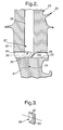
- Figs. 2 and 3 illustrate a second embodiment of the present invention.
- a mounting hub or disk 21 has a turbine blade 23 secured to it with a gap between a blade root end 22 and a top surface 32 of the mounting hub or disk 21.
- This gap is a coolant gallery 24 through which a coolant flow shown by arrow head 25 passes in order to enter through a passage opening 27 a passage 28 coupled to a coolant passage network of the turbine blade 23.
- the coolant air flow 25 is deflected by a flow deflector 26 associated and adjacent to the passage opening 27.
- This flow deflector 26 is located substantially around the passage opening 27 to block the gallery 24 by a close fit association.
- bypass holes are provided to the respective sides of the deflector 26, coolant air flow 25 can bypass the flow deflector 26 on either side to impinge upon other flow deflectors within the coolant gallery 24.
- the flow deflector 26 has a curved surface 30 which acts as a scoop in order to progressively deflect the coolant air flow 25 through the opening 27 into the passage 28.
- the flow deflector 26 acts substantially in the same fashion as that described with respect to flow deflector 6 (Fig. 1) but rather than providing a flat wedge or ramp aspect to the coolant air flow 25 has a curved scoop for gradual flow deflection through the passage opening 27 into the passage 28.
- the flow deflector 26 is an integral part of the blade root end 22.
- the flow deflector 26 may be machined or cast with the blade root end 22 during manufacture.
- a sacrificial ceramic core shown in broken line 31 may be located within the opening 27 during casting or machining of the flow deflector 26 such that once fabrication is complete the core 31 is removed to leave the flow deflector 26 extending below the opening 27.
- the flow deflector 26 will extend substantially into contact with the upper surface 32 of the mounting hub or disk 21.
- the bottom edge of the flow deflector 26 may be spaced from the upper surface 32 to accommodate for expansion and/or contraction of the hub or disk 21 and turbine blade 23 such that overly compressive engagement is avoided and so possible detrimental stressing of the flow deflector 26 is prevented.
- flow deflector 26 as with flow deflector 6 (Fig. 1) could be part of the upper surface 32 of the hub or disk 21 rather than an integral part of the blade root end 22.
- the flow deflector 26 could be a separate component or insert appropriately secured in association with the opening 27 as required.
- angles of inclination for the wedge or ramp configuration of flow deflector 6 (Fig. 1) or the rate of curvature in the scoop flow deflector 26 will be design choices made dependent upon expected coolant air flow rates, necessary cooling efficiency and other operational factors. As indicated above, by appropriate choice of materials in terms of relative expansion/contraction, these angles of inclination and curvature may be slightly altered through a temperature range in order to adjust the degree of progressive deflection of the coolant flow into the passage leading to the coolant passage network of a turbine blade.
- Fig. 3 illustrates a cross-section of the flow deflector 26 in the plane AB, as can be seen, the scoop or curved wall surface 30 takes the form of a cavity removed from a block cross-section 33.
- This enables the flow deflector 26 to partially envelope or surround the hole which defines the passage opening 27 so improving coolant air flow 25 deflection into the passage 28 through the opening 27.
- the greater dimensions of the block 33 will render the flow deflector 26 more robust potentially in service than the flat flow deflector 6 but will also marginally increase weight for the blade 23 particularly if several flow deflectors are utilised in each blade 23.
- a flow deflector 6, 26 The principal function of a flow deflector 6, 26 is to deflect a lateral coolant air flow 5, 25 along the distribution gallery 4, 24 into an opening 7, 27 which is perpendicular to that flow 5, 25.
- the deflector 6, 26 deflects that planar front such that there is greater overlap with the plane of the opening 7, 27 for entry.
- planar deflection should be in the order of 90° or that required for in-line incidence but normally a balance is struck between the severity of deflection (which effects net positive pressure loss) and the level of flow planar front overlap with the opening 7, 27 (alignment would be an ideal coupling of flow into the opening 7, 27 but normally the deflected flow planar front will be skew of the plane of the opening).
Landscapes
- Engineering & Computer Science (AREA)
- Mechanical Engineering (AREA)
- General Engineering & Computer Science (AREA)
- Turbine Rotor Nozzle Sealing (AREA)
Applications Claiming Priority (2)
| Application Number | Priority Date | Filing Date | Title |
|---|---|---|---|
| GBGB0227745.7A GB0227745D0 (en) | 2002-11-28 | 2002-11-28 | Blade cooling |
| GB0227745 | 2002-11-28 |
Publications (3)
| Publication Number | Publication Date |
|---|---|
| EP1424468A2 true EP1424468A2 (de) | 2004-06-02 |
| EP1424468A3 EP1424468A3 (de) | 2006-05-10 |
| EP1424468B1 EP1424468B1 (de) | 2015-06-17 |
Family
ID=9948677
Family Applications (1)
| Application Number | Title | Priority Date | Filing Date |
|---|---|---|---|
| EP03257022.8A Expired - Lifetime EP1424468B1 (de) | 2002-11-28 | 2003-11-06 | Kühlanordnung einer Gasturbinenschaufel |
Country Status (3)
| Country | Link |
|---|---|
| US (3) | US7198466B2 (de) |
| EP (1) | EP1424468B1 (de) |
| GB (1) | GB0227745D0 (de) |
Cited By (1)
| Publication number | Priority date | Publication date | Assignee | Title |
|---|---|---|---|---|
| ITMI20090977A1 (it) * | 2009-06-04 | 2010-12-05 | Ansaldo Energia Spa | Pala di turbina |
Families Citing this family (2)
| Publication number | Priority date | Publication date | Assignee | Title |
|---|---|---|---|---|
| DE102015111746A1 (de) * | 2015-07-20 | 2017-01-26 | Rolls-Royce Deutschland Ltd & Co Kg | Gekühltes Turbinenlaufrad, insbesondere für ein Flugtriebwerk |
| US12410712B1 (en) | 2024-09-24 | 2025-09-09 | Pratt & Whitney Canada Corp. | Rotor blade with apertured cooling air deflector |
Family Cites Families (15)
| Publication number | Priority date | Publication date | Assignee | Title |
|---|---|---|---|---|
| US2440069A (en) * | 1944-08-26 | 1948-04-20 | Gen Electric | High-temperature elastic fluid turbine |
| GB1561229A (en) | 1977-02-18 | 1980-02-13 | Rolls Royce | Gas turbine engine cooling system |
| US4275990A (en) * | 1977-12-17 | 1981-06-30 | Rolls-Royce Limited | Disc channel for cooling rotor blade roots |
| US4348157A (en) * | 1978-10-26 | 1982-09-07 | Rolls-Royce Limited | Air cooled turbine for a gas turbine engine |
| GB2252368B (en) * | 1981-03-20 | 1993-02-17 | Rolls Royce | Liquid cooled aerofoil blade |
| US4626169A (en) * | 1983-12-13 | 1986-12-02 | United Technologies Corporation | Seal means for a blade attachment slot of a rotor assembly |
| US4898514A (en) * | 1987-10-27 | 1990-02-06 | United Technologies Corporation | Turbine balance arrangement with integral air passage |
| US4820123A (en) | 1988-04-25 | 1989-04-11 | United Technologies Corporation | Dirt removal means for air cooled blades |
| DE3835932A1 (de) | 1988-10-21 | 1990-04-26 | Mtu Muenchen Gmbh | Vorrichtung zur kuehlluftzufuehrung fuer gasturbinen-rotorschaufeln |
| US5403156A (en) * | 1993-10-26 | 1995-04-04 | United Technologies Corporation | Integral meter plate for turbine blade and method |
| US5827043A (en) | 1997-06-27 | 1998-10-27 | United Technologies Corporation | Coolable airfoil |
| US6059529A (en) * | 1998-03-16 | 2000-05-09 | Siemens Westinghouse Power Corporation | Turbine blade assembly with cooling air handling device |
| US6474946B2 (en) * | 2001-02-26 | 2002-11-05 | United Technologies Corporation | Attachment air inlet configuration for highly loaded single crystal turbine blades |
| FR2823794B1 (fr) * | 2001-04-19 | 2003-07-11 | Snecma Moteurs | Aube rapportee et refroidie pour turbine |
| US7534085B2 (en) * | 2006-06-21 | 2009-05-19 | United Technologies Corporation | Gas turbine engine with contoured air supply slot in turbine rotor |
-
2002
- 2002-11-28 GB GBGB0227745.7A patent/GB0227745D0/en not_active Ceased
-
2003
- 2003-11-06 EP EP03257022.8A patent/EP1424468B1/de not_active Expired - Lifetime
- 2003-11-25 US US10/720,333 patent/US7198466B2/en not_active Expired - Lifetime
-
2006
- 2006-09-25 US US11/525,931 patent/US20070031251A1/en not_active Abandoned
-
2009
- 2009-01-07 US US12/318,722 patent/US20090136358A1/en not_active Abandoned
Cited By (3)
| Publication number | Priority date | Publication date | Assignee | Title |
|---|---|---|---|---|
| ITMI20090977A1 (it) * | 2009-06-04 | 2010-12-05 | Ansaldo Energia Spa | Pala di turbina |
| WO2010139766A1 (en) * | 2009-06-04 | 2010-12-09 | Ansaldo Energia S.P.A. | Turbine blade |
| RU2528781C2 (ru) * | 2009-06-04 | 2014-09-20 | Ансальдо Энергия С.П.А. | Лопатка турбины |
Also Published As
| Publication number | Publication date |
|---|---|
| US20050226725A1 (en) | 2005-10-13 |
| EP1424468B1 (de) | 2015-06-17 |
| EP1424468A3 (de) | 2006-05-10 |
| US20090136358A1 (en) | 2009-05-28 |
| US20070031251A1 (en) | 2007-02-08 |
| US7198466B2 (en) | 2007-04-03 |
| GB0227745D0 (en) | 2003-01-08 |
Similar Documents
| Publication | Publication Date | Title |
|---|---|---|
| EP1452694B1 (de) | Dämpfungs- und Dichtungselement für Turbine | |
| EP1953343B1 (de) | Kühlsystem für eine Gasturbinenschaufel und enstprechende Gasturbinenschaufel | |
| US7351035B2 (en) | Hollow rotor blade for the turbine of a gas turbine engine, the blade being fitted with a “bathtub” | |
| EP1106781B1 (de) | Gekühlte Stator- oder Rotorschaufel für eine Turbomaschine | |
| US8596961B2 (en) | Aerofoil and method for making an aerofoil | |
| US4424001A (en) | Tip structure for cooled turbine rotor blade | |
| US7744347B2 (en) | Peripheral microcircuit serpentine cooling for turbine airfoils | |
| CN101148994B (zh) | 灰孔圆顶叶片 | |
| EP1865152B1 (de) | Mikrokühlkanäle für Turbinenschaufeln | |
| US20090226322A1 (en) | Airfoil design for rotor and stator blades of a turbomachine | |
| EP1262635B1 (de) | Verstellbare Schaufel für Turbomaschinen | |
| US20120014810A1 (en) | Turbine vane with dusting hole at the base of the blade | |
| US6464460B2 (en) | Turbine blade with actively cooled shroud-band element | |
| CN112074652A (zh) | 用于涡轮叶片的叶片 | |
| EP2562358A1 (de) | Spaltring-kühlstruktur und gasturbine | |
| US6309175B1 (en) | Platform cooling in turbomachines | |
| US9341069B2 (en) | Gas turbine | |
| US7661930B2 (en) | Central cooling circuit for a moving blade of a turbomachine | |
| US20090136358A1 (en) | Blade cooling | |
| JP3895195B2 (ja) | タービンブレード用の取付部の空気入口形状 | |
| EP1728970B1 (de) | Kühlsystem für Turbinenschaufel | |
| US7004721B2 (en) | Annular platform for a nozzle of a low-pressure turbine of a turbomachine | |
| EP1213442B1 (de) | Rotorschaufel | |
| KR102874670B1 (ko) | 터빈 블레이드 및 그 가공 방법 | |
| EP1749970A2 (de) | Verlängerung der Plattform einer Turbinenschaufel mit einer niedrigen Spannung in seinem Stützpfeiler |
Legal Events
| Date | Code | Title | Description |
|---|---|---|---|
| PUAI | Public reference made under article 153(3) epc to a published international application that has entered the european phase |
Free format text: ORIGINAL CODE: 0009012 |
|
| AK | Designated contracting states |
Kind code of ref document: A2 Designated state(s): AT BE BG CH CY CZ DE DK EE ES FI FR GB GR HU IE IT LI LU MC NL PT RO SE SI SK TR |
|
| AX | Request for extension of the european patent |
Extension state: AL LT LV MK |
|
| PUAL | Search report despatched |
Free format text: ORIGINAL CODE: 0009013 |
|
| AK | Designated contracting states |
Kind code of ref document: A3 Designated state(s): AT BE BG CH CY CZ DE DK EE ES FI FR GB GR HU IE IT LI LU MC NL PT RO SE SI SK TR |
|
| AX | Request for extension of the european patent |
Extension state: AL LT LV MK |
|
| RIC1 | Information provided on ipc code assigned before grant |
Ipc: F01D 5/08 20060101ALI20060323BHEP Ipc: F01D 5/18 20060101AFI20040114BHEP |
|
| 17P | Request for examination filed |
Effective date: 20060427 |
|
| AKX | Designation fees paid |
Designated state(s): DE FR GB |
|
| 17Q | First examination report despatched |
Effective date: 20071010 |
|
| GRAP | Despatch of communication of intention to grant a patent |
Free format text: ORIGINAL CODE: EPIDOSNIGR1 |
|
| GRAS | Grant fee paid |
Free format text: ORIGINAL CODE: EPIDOSNIGR3 |
|
| INTG | Intention to grant announced |
Effective date: 20150408 |
|
| GRAA | (expected) grant |
Free format text: ORIGINAL CODE: 0009210 |
|
| AK | Designated contracting states |
Kind code of ref document: B1 Designated state(s): DE FR GB |
|
| REG | Reference to a national code |
Ref country code: GB Ref legal event code: FG4D |
|
| RAP2 | Party data changed (patent owner data changed or rights of a patent transferred) |
Owner name: ROLLS-ROYCE PLC |
|
| REG | Reference to a national code |
Ref country code: DE Ref legal event code: R096 Ref document number: 60347708 Country of ref document: DE |
|
| REG | Reference to a national code |
Ref country code: FR Ref legal event code: PLFP Year of fee payment: 13 |
|
| REG | Reference to a national code |
Ref country code: DE Ref legal event code: R097 Ref document number: 60347708 Country of ref document: DE |
|
| PLBE | No opposition filed within time limit |
Free format text: ORIGINAL CODE: 0009261 |
|
| STAA | Information on the status of an ep patent application or granted ep patent |
Free format text: STATUS: NO OPPOSITION FILED WITHIN TIME LIMIT |
|
| 26N | No opposition filed |
Effective date: 20160318 |
|
| REG | Reference to a national code |
Ref country code: DE Ref legal event code: R082 Ref document number: 60347708 Country of ref document: DE Representative=s name: HERNANDEZ, YORCK, DIPL.-ING., DE |
|
| REG | Reference to a national code |
Ref country code: FR Ref legal event code: PLFP Year of fee payment: 14 |
|
| REG | Reference to a national code |
Ref country code: FR Ref legal event code: PLFP Year of fee payment: 15 |
|
| PGFP | Annual fee paid to national office [announced via postgrant information from national office to epo] |
Ref country code: GB Payment date: 20201126 Year of fee payment: 18 Ref country code: FR Payment date: 20201126 Year of fee payment: 18 |
|
| PGFP | Annual fee paid to national office [announced via postgrant information from national office to epo] |
Ref country code: DE Payment date: 20210128 Year of fee payment: 18 |
|
| REG | Reference to a national code |
Ref country code: DE Ref legal event code: R119 Ref document number: 60347708 Country of ref document: DE |
|
| GBPC | Gb: european patent ceased through non-payment of renewal fee |
Effective date: 20211106 |
|
| PG25 | Lapsed in a contracting state [announced via postgrant information from national office to epo] |
Ref country code: GB Free format text: LAPSE BECAUSE OF NON-PAYMENT OF DUE FEES Effective date: 20211106 Ref country code: DE Free format text: LAPSE BECAUSE OF NON-PAYMENT OF DUE FEES Effective date: 20220601 |
|
| PG25 | Lapsed in a contracting state [announced via postgrant information from national office to epo] |
Ref country code: FR Free format text: LAPSE BECAUSE OF NON-PAYMENT OF DUE FEES Effective date: 20211130 |