EP1424144A1 - Method of recycling plastic material of process cartridge - Google Patents
Method of recycling plastic material of process cartridge Download PDFInfo
- Publication number
- EP1424144A1 EP1424144A1 EP03027101A EP03027101A EP1424144A1 EP 1424144 A1 EP1424144 A1 EP 1424144A1 EP 03027101 A EP03027101 A EP 03027101A EP 03027101 A EP03027101 A EP 03027101A EP 1424144 A1 EP1424144 A1 EP 1424144A1
- Authority
- EP
- European Patent Office
- Prior art keywords
- process cartridge
- plastic material
- toner
- crushed
- separated
- Prior art date
- Legal status (The legal status is an assumption and is not a legal conclusion. Google has not performed a legal analysis and makes no representation as to the accuracy of the status listed.)
- Granted
Links
Images




Classifications
-
- B—PERFORMING OPERATIONS; TRANSPORTING
- B29—WORKING OF PLASTICS; WORKING OF SUBSTANCES IN A PLASTIC STATE IN GENERAL
- B29B—PREPARATION OR PRETREATMENT OF THE MATERIAL TO BE SHAPED; MAKING GRANULES OR PREFORMS; RECOVERY OF PLASTICS OR OTHER CONSTITUENTS OF WASTE MATERIAL CONTAINING PLASTICS
- B29B17/00—Recovery of plastics or other constituents of waste material containing plastics
- B29B17/04—Disintegrating plastics, e.g. by milling
-
- B—PERFORMING OPERATIONS; TRANSPORTING
- B03—SEPARATION OF SOLID MATERIALS USING LIQUIDS OR USING PNEUMATIC TABLES OR JIGS; MAGNETIC OR ELECTROSTATIC SEPARATION OF SOLID MATERIALS FROM SOLID MATERIALS OR FLUIDS; SEPARATION BY HIGH-VOLTAGE ELECTRIC FIELDS
- B03B—SEPARATING SOLID MATERIALS USING LIQUIDS OR USING PNEUMATIC TABLES OR JIGS
- B03B9/00—General arrangement of separating plant, e.g. flow sheets
- B03B9/06—General arrangement of separating plant, e.g. flow sheets specially adapted for refuse
- B03B9/061—General arrangement of separating plant, e.g. flow sheets specially adapted for refuse the refuse being industrial
-
- B—PERFORMING OPERATIONS; TRANSPORTING
- B07—SEPARATING SOLIDS FROM SOLIDS; SORTING
- B07C—POSTAL SORTING; SORTING INDIVIDUAL ARTICLES, OR BULK MATERIAL FIT TO BE SORTED PIECE-MEAL, e.g. BY PICKING
- B07C5/00—Sorting according to a characteristic or feature of the articles or material being sorted, e.g. by control effected by devices which detect or measure such characteristic or feature; Sorting by manually actuated devices, e.g. switches
- B07C5/34—Sorting according to other particular properties
-
- B—PERFORMING OPERATIONS; TRANSPORTING
- B09—DISPOSAL OF SOLID WASTE; RECLAMATION OF CONTAMINATED SOIL
- B09B—DISPOSAL OF SOLID WASTE NOT OTHERWISE PROVIDED FOR
- B09B3/00—Destroying solid waste or transforming solid waste into something useful or harmless
- B09B3/30—Destroying solid waste or transforming solid waste into something useful or harmless involving mechanical treatment
- B09B3/35—Shredding, crushing or cutting
-
- B—PERFORMING OPERATIONS; TRANSPORTING
- B29—WORKING OF PLASTICS; WORKING OF SUBSTANCES IN A PLASTIC STATE IN GENERAL
- B29B—PREPARATION OR PRETREATMENT OF THE MATERIAL TO BE SHAPED; MAKING GRANULES OR PREFORMS; RECOVERY OF PLASTICS OR OTHER CONSTITUENTS OF WASTE MATERIAL CONTAINING PLASTICS
- B29B17/00—Recovery of plastics or other constituents of waste material containing plastics
- B29B17/02—Separating plastics from other materials
-
- G—PHYSICS
- G03—PHOTOGRAPHY; CINEMATOGRAPHY; ANALOGOUS TECHNIQUES USING WAVES OTHER THAN OPTICAL WAVES; ELECTROGRAPHY; HOLOGRAPHY
- G03G—ELECTROGRAPHY; ELECTROPHOTOGRAPHY; MAGNETOGRAPHY
- G03G15/00—Apparatus for electrographic processes using a charge pattern
- G03G15/06—Apparatus for electrographic processes using a charge pattern for developing
- G03G15/08—Apparatus for electrographic processes using a charge pattern for developing using a solid developer, e.g. powder developer
- G03G15/0894—Reconditioning of the developer unit, i.e. reusing or recycling parts of the unit, e.g. resealing of the unit before refilling with toner
-
- B—PERFORMING OPERATIONS; TRANSPORTING
- B29—WORKING OF PLASTICS; WORKING OF SUBSTANCES IN A PLASTIC STATE IN GENERAL
- B29B—PREPARATION OR PRETREATMENT OF THE MATERIAL TO BE SHAPED; MAKING GRANULES OR PREFORMS; RECOVERY OF PLASTICS OR OTHER CONSTITUENTS OF WASTE MATERIAL CONTAINING PLASTICS
- B29B17/00—Recovery of plastics or other constituents of waste material containing plastics
- B29B17/02—Separating plastics from other materials
- B29B2017/0213—Specific separating techniques
- B29B2017/0217—Mechanical separating techniques; devices therefor
- B29B2017/0224—Screens, sieves
-
- B—PERFORMING OPERATIONS; TRANSPORTING
- B29—WORKING OF PLASTICS; WORKING OF SUBSTANCES IN A PLASTIC STATE IN GENERAL
- B29B—PREPARATION OR PRETREATMENT OF THE MATERIAL TO BE SHAPED; MAKING GRANULES OR PREFORMS; RECOVERY OF PLASTICS OR OTHER CONSTITUENTS OF WASTE MATERIAL CONTAINING PLASTICS
- B29B17/00—Recovery of plastics or other constituents of waste material containing plastics
- B29B17/02—Separating plastics from other materials
- B29B2017/0213—Specific separating techniques
- B29B2017/0217—Mechanical separating techniques; devices therefor
- B29B2017/0227—Vibratory or shaking tables
-
- B—PERFORMING OPERATIONS; TRANSPORTING
- B29—WORKING OF PLASTICS; WORKING OF SUBSTANCES IN A PLASTIC STATE IN GENERAL
- B29B—PREPARATION OR PRETREATMENT OF THE MATERIAL TO BE SHAPED; MAKING GRANULES OR PREFORMS; RECOVERY OF PLASTICS OR OTHER CONSTITUENTS OF WASTE MATERIAL CONTAINING PLASTICS
- B29B17/00—Recovery of plastics or other constituents of waste material containing plastics
- B29B17/02—Separating plastics from other materials
- B29B2017/0213—Specific separating techniques
- B29B2017/0217—Mechanical separating techniques; devices therefor
- B29B2017/0237—Mechanical separating techniques; devices therefor using density difference
-
- B—PERFORMING OPERATIONS; TRANSPORTING
- B29—WORKING OF PLASTICS; WORKING OF SUBSTANCES IN A PLASTIC STATE IN GENERAL
- B29B—PREPARATION OR PRETREATMENT OF THE MATERIAL TO BE SHAPED; MAKING GRANULES OR PREFORMS; RECOVERY OF PLASTICS OR OTHER CONSTITUENTS OF WASTE MATERIAL CONTAINING PLASTICS
- B29B17/00—Recovery of plastics or other constituents of waste material containing plastics
- B29B17/02—Separating plastics from other materials
- B29B2017/0213—Specific separating techniques
- B29B2017/0217—Mechanical separating techniques; devices therefor
- B29B2017/0237—Mechanical separating techniques; devices therefor using density difference
- B29B2017/0241—Mechanical separating techniques; devices therefor using density difference in gas, e.g. air flow
-
- B—PERFORMING OPERATIONS; TRANSPORTING
- B29—WORKING OF PLASTICS; WORKING OF SUBSTANCES IN A PLASTIC STATE IN GENERAL
- B29B—PREPARATION OR PRETREATMENT OF THE MATERIAL TO BE SHAPED; MAKING GRANULES OR PREFORMS; RECOVERY OF PLASTICS OR OTHER CONSTITUENTS OF WASTE MATERIAL CONTAINING PLASTICS
- B29B17/00—Recovery of plastics or other constituents of waste material containing plastics
- B29B17/02—Separating plastics from other materials
- B29B2017/0213—Specific separating techniques
- B29B2017/0268—Separation of metals
- B29B2017/0272—Magnetic separation
-
- B—PERFORMING OPERATIONS; TRANSPORTING
- B29—WORKING OF PLASTICS; WORKING OF SUBSTANCES IN A PLASTIC STATE IN GENERAL
- B29B—PREPARATION OR PRETREATMENT OF THE MATERIAL TO BE SHAPED; MAKING GRANULES OR PREFORMS; RECOVERY OF PLASTICS OR OTHER CONSTITUENTS OF WASTE MATERIAL CONTAINING PLASTICS
- B29B17/00—Recovery of plastics or other constituents of waste material containing plastics
- B29B17/02—Separating plastics from other materials
- B29B2017/0213—Specific separating techniques
- B29B2017/0279—Optical identification, e.g. cameras or spectroscopy
-
- B—PERFORMING OPERATIONS; TRANSPORTING
- B29—WORKING OF PLASTICS; WORKING OF SUBSTANCES IN A PLASTIC STATE IN GENERAL
- B29K—INDEXING SCHEME ASSOCIATED WITH SUBCLASSES B29B, B29C OR B29D, RELATING TO MOULDING MATERIALS OR TO MATERIALS FOR MOULDS, REINFORCEMENTS, FILLERS OR PREFORMED PARTS, e.g. INSERTS
- B29K2023/00—Use of polyalkenes or derivatives thereof as moulding material
- B29K2023/10—Polymers of propylene
- B29K2023/12—PP, i.e. polypropylene
-
- B—PERFORMING OPERATIONS; TRANSPORTING
- B29—WORKING OF PLASTICS; WORKING OF SUBSTANCES IN A PLASTIC STATE IN GENERAL
- B29K—INDEXING SCHEME ASSOCIATED WITH SUBCLASSES B29B, B29C OR B29D, RELATING TO MOULDING MATERIALS OR TO MATERIALS FOR MOULDS, REINFORCEMENTS, FILLERS OR PREFORMED PARTS, e.g. INSERTS
- B29K2025/00—Use of polymers of vinyl-aromatic compounds or derivatives thereof as moulding material
-
- B—PERFORMING OPERATIONS; TRANSPORTING
- B29—WORKING OF PLASTICS; WORKING OF SUBSTANCES IN A PLASTIC STATE IN GENERAL
- B29K—INDEXING SCHEME ASSOCIATED WITH SUBCLASSES B29B, B29C OR B29D, RELATING TO MOULDING MATERIALS OR TO MATERIALS FOR MOULDS, REINFORCEMENTS, FILLERS OR PREFORMED PARTS, e.g. INSERTS
- B29K2055/00—Use of specific polymers obtained by polymerisation reactions only involving carbon-to-carbon unsaturated bonds, not provided for in a single one of main groups B29K2023/00 - B29K2049/00, e.g. having a vinyl group, as moulding material
- B29K2055/02—ABS polymers, i.e. acrylonitrile-butadiene-styrene polymers
-
- B—PERFORMING OPERATIONS; TRANSPORTING
- B29—WORKING OF PLASTICS; WORKING OF SUBSTANCES IN A PLASTIC STATE IN GENERAL
- B29K—INDEXING SCHEME ASSOCIATED WITH SUBCLASSES B29B, B29C OR B29D, RELATING TO MOULDING MATERIALS OR TO MATERIALS FOR MOULDS, REINFORCEMENTS, FILLERS OR PREFORMED PARTS, e.g. INSERTS
- B29K2059/00—Use of polyacetals, e.g. POM, i.e. polyoxymethylene or derivatives thereof, as moulding material
-
- B—PERFORMING OPERATIONS; TRANSPORTING
- B29—WORKING OF PLASTICS; WORKING OF SUBSTANCES IN A PLASTIC STATE IN GENERAL
- B29L—INDEXING SCHEME ASSOCIATED WITH SUBCLASS B29C, RELATING TO PARTICULAR ARTICLES
- B29L2031/00—Other particular articles
- B29L2031/767—Printing equipment or accessories therefor
-
- B—PERFORMING OPERATIONS; TRANSPORTING
- B29—WORKING OF PLASTICS; WORKING OF SUBSTANCES IN A PLASTIC STATE IN GENERAL
- B29L—INDEXING SCHEME ASSOCIATED WITH SUBCLASS B29C, RELATING TO PARTICULAR ARTICLES
- B29L2031/00—Other particular articles
- B29L2031/767—Printing equipment or accessories therefor
- B29L2031/7678—Ink or toner cartridges
-
- Y—GENERAL TAGGING OF NEW TECHNOLOGICAL DEVELOPMENTS; GENERAL TAGGING OF CROSS-SECTIONAL TECHNOLOGIES SPANNING OVER SEVERAL SECTIONS OF THE IPC; TECHNICAL SUBJECTS COVERED BY FORMER USPC CROSS-REFERENCE ART COLLECTIONS [XRACs] AND DIGESTS
- Y02—TECHNOLOGIES OR APPLICATIONS FOR MITIGATION OR ADAPTATION AGAINST CLIMATE CHANGE
- Y02W—CLIMATE CHANGE MITIGATION TECHNOLOGIES RELATED TO WASTEWATER TREATMENT OR WASTE MANAGEMENT
- Y02W30/00—Technologies for solid waste management
- Y02W30/50—Reuse, recycling or recovery technologies
- Y02W30/52—Mechanical processing of waste for the recovery of materials, e.g. crushing, shredding, separation or disassembly
-
- Y—GENERAL TAGGING OF NEW TECHNOLOGICAL DEVELOPMENTS; GENERAL TAGGING OF CROSS-SECTIONAL TECHNOLOGIES SPANNING OVER SEVERAL SECTIONS OF THE IPC; TECHNICAL SUBJECTS COVERED BY FORMER USPC CROSS-REFERENCE ART COLLECTIONS [XRACs] AND DIGESTS
- Y02—TECHNOLOGIES OR APPLICATIONS FOR MITIGATION OR ADAPTATION AGAINST CLIMATE CHANGE
- Y02W—CLIMATE CHANGE MITIGATION TECHNOLOGIES RELATED TO WASTEWATER TREATMENT OR WASTE MANAGEMENT
- Y02W30/00—Technologies for solid waste management
- Y02W30/50—Reuse, recycling or recovery technologies
- Y02W30/62—Plastics recycling; Rubber recycling
-
- Y—GENERAL TAGGING OF NEW TECHNOLOGICAL DEVELOPMENTS; GENERAL TAGGING OF CROSS-SECTIONAL TECHNOLOGIES SPANNING OVER SEVERAL SECTIONS OF THE IPC; TECHNICAL SUBJECTS COVERED BY FORMER USPC CROSS-REFERENCE ART COLLECTIONS [XRACs] AND DIGESTS
- Y10—TECHNICAL SUBJECTS COVERED BY FORMER USPC
- Y10T—TECHNICAL SUBJECTS COVERED BY FORMER US CLASSIFICATION
- Y10T29/00—Metal working
- Y10T29/49—Method of mechanical manufacture
- Y10T29/49751—Scrap recovering or utilizing
- Y10T29/49755—Separating one material from another
Definitions
- the present invention relates to a method of recycling plastic materials forming a process cartridge.
- the present invention particularly relates to a method of recycling a specific plastic material from plastic materials forming a process cartridge.
- the present invention further relates to a method of recycling a plastic material having a predetermined reflection density from plastic materials forming a process cartridge.
- a process cartridge is a product made up of parts and materials required for image formation, e.g., a photosensitive drum, charger, cleaner, and toner, and detachably incorporated into a copying machine or printer.
- Japanese Patent Laid-Open No. 09-150137 is prior information concerning a method of discarding a unit containing toner.
- Japanese Patent Laid-Open Nos. 05-301222 and 2000-159900 are inventions pertaining to the reuse of thermoplastic resins used in products such as copying machines, printers, facsimile apparatuses, and television sets.
- Japanese Patent Laid-Open No. 2001-205245 is an invention related to a process of separating toner from a used process cartridge.
- Japanese Patent Laid-Open No. 09-206685 is an invention concerning particle processing.
- Image forming apparatuses such as copying machines and laser beam printers have rapidly spread with the progress of information communication technologies and the development of information communication apparatuses. Also, old apparatuses are extensively replaced with new ones as new products are developed.
- sparks generated when metal parts such as agitating bars, developing blades, and sleeves inside these cartridges are crushed by the crusher may function as ignition sources and induce dust explosion.
- toner can be separated from plastic materials by introducing an apparatus using a cleaning device.
- plastic materials e.g., HIPS
- the flow characteristics of a resin material may change during molding to make the molding process difficult, or the strength of the cartridge may lower.
- the color of the molded cartridge changes, and the color uniformity is lost.
- plastic materials which are subjected to a cleaning step and to which toner is sticking are selected in a plastic selection step, different plastic materials adhere to each other under the influence of water or the cleaner used.
- a method of recycling a plastic material of a process cartridge according to the present invention is characterized in that the process cartridge is crushed in a crushing step while particles such as toner are collected by suction, particles including toner are further removed in a screening step, metal materials are removed in a magnetic selection step, drum magnetic selection step, and eddy current step, particles including toner and foreign matter are removed in an air selection step, secondary crushing step, peeling step, and gravity separation step, and the remaining materials are conveyed to a color selection step by a conveyor means to separate a plastic material having a reflection density of 1.00 or more.
- Fig. 1 is a sectional view for explaining a process cartridge to which the present invention is applied.
- a process cartridge 1 is made up of a plastic vessel 2 as a main body, and a photosensitive drum 4, charging roller 6, cleaning blade 8, and developing sleeve 10 assembled in the vessel 2.
- the vessel 2 forms a toner container 1a which contains toner scraped off from the photosensitive drum 4 during a development process.
- the photosensitive drum 4 is formed by coating the surface of an aluminum drum with a photosensitive material.
- a driving gear made of plastic is attached to a drum end portion.
- the charging roller 6 is formed by molding a rubber roller on an iron shaft.
- the cleaning blade 8 is obtained by fixing a rubber blade plate to an iron base.
- the developing sleeve 10 is made of aluminum and contains a magnet.
- This process cartridge is made of metal materials such as iron, aluminum, and stainless steel (SUS), and various other materials such as rubber materials, plastic materials, and tape materials.
- Fig. 2 shows a process of recycling a plastic material of the process cartridge according to the present invention into a recycled plastic material.
- step 1 of Fig. 2 collected process cartridges are crushed while toner is collected by suction (a primary crushing step).
- Fig. 3 shows means and apparatuses from the primary crushing step in step 1 to an eddy current selection step in step 5 shown in Fig. 2.
- Step 1 shown in Fig. 3 shows an outline of the structure of a crushing apparatus 20 used in the crushing step.
- a rotary blade 20B is placed in a steel vessel 20A.
- a predetermined amount (number) of process cartridges containing toner are placed in the crushing vessel.
- these cartridges are flung up by the rotary blade and crushed as they are thrown against the circumferential wall of the vessel.
- an inert gas such as nitrogen gas is supplied into the vessel 20A to maintain the oxygen concentration in the vessel at a predetermined concentration or less (10% or less).
- the rotational speed of the rotary blade and the crushing time can be set in accordance with the type of process cartridge.
- a suction chamber 20C is formed adjacent to the crushing vessel 20A.
- the crushed product of the cartridges crushed by the crushing vessel 20A is supplied into the suction chamber 20C.
- An impacting means applies impact to the crushed product to float toner sticking to the crushed product.
- a suction means collects the floated toner by suction.
- the process up to this point is the primary crushing step.
- step 1 The purpose of step 1 is to separate toner and paper dust.
- a screen selection step in step 2 of Fig. 3 shows a selection step using a shaking screen.
- the crushed product subjected to the impacting process and suction process in the suction chamber 20C is then subjected to a selecting operation by a shaking screen selecting means 22.
- step 2 toner, paper dust, and fine particles of plastic materials produced in the crushing step are separated.
- Step 3 shows a metal selection step in which a magnetic selecting means selects iron members from the crushed product subjected to the shaking screen selection step.
- a magnetic selecting means selects iron members from the crushed product subjected to the shaking screen selection step.
- cleaning blades and drum shafts are separated.
- Step 4 uses a drum magnetic selecting means. In step 4, small iron parts and plastic magnets are separated.
- step 5 aluminum members such as drums and developing sleeves are selected by an eddy current selecting means.
- Fig. 4 shows steps 6 and 7.
- Step 6 is an air selection step in which stainless steel parts and small metal parts are removed by air.
- Step 7 is a secondary crushing step in which the crushed product subjected to the steps up to step 6 is further crushed more finely by a crushing apparatus.
- Fig. 5 shows step 8.
- Step 8 is a peeling step for the crushed product subjected to the crushing operation in the secondary crushing step.
- labels, seals, and fine particles sticking to the plastic crushed product subjected to the processes such as crushing are separated by a peeling operation and air operation.
- Fig. 6 shows steps 9 and 10.
- Step 9 is a dry gravity separation step in which metals, polyethylene, and foamed urethanes are removed.
- Step 10 is a color selection step.
- the crushed product subjected to the process in step S9 is placed in a hopper and then placed on a conveyor belt from the exit of the hopper.
- the crushed product is placed on the conveyor belt so as to form a layer of the crushed product on the belt.
- a large number of color selecting elements are arranged in the widthwise direction of the belt near its end position.
- compressing means are arranged in positions corresponding to these color selecting elements.
- the crushed pieces as objects of selection placed on the belt are individually subjected to color selection by the color selecting means before the end portion of the belt.
- Each color selecting element reads the color density of a crushed piece as an object of selection by a light emitting/receiving type color selecting operation, and sends the read color density to a selection control means which compares the color density with a reference color density.
- the selection control means operates a compressing means to spring out a crushed piece outside the reference density range, thereby selecting only crushed pieces within the reference density range.
- step 10 a metal sensing step is performed for the crushed pieces subjected to the color selection, thereby removing metals.
- the crushed pieces subjected to color selection in the color selection step are already crushed into very small pieces in the previous steps. Therefore, if these crushed pieces are not well dried before the color selection step, the crushed pieces adhere to each other. Since crushed pieces having different colors adhere to each other, the degree of expectation to the selection performance of the color selecting elements lowers. In some cases, the color selection accuracy lowers.
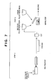
- Fig. 7 shows steps 11 and 12.
- step 11 the crushed pieces processed in step 10 are melted, cooled, and cut to form a material of recycled plastic.
- step 12 the material of recycled plastic processed in step 11 is mixed with a new plastic material to form a recycled plastic material for molding.
- Steps 11 and 12 may also be switched to first mix the recycled plastic pieces with a new plastic material, and then melt, cool, and cut the mixture to obtain a material of recycled plastic.
- a process cartridge used in this example was a process cartridge of a laser beam printer manufactured and sold by the present applicant.
- This cartridge is formed by using metals such as iron, aluminum, stainless steel, and copper, rubbers such as silicone rubber and urethane rubber, resins such as a styrene resin (PS), polyacetal resin (POM), polypropyrene (PP), polyethylene (PE), and polyethyleneterephthalate (PET), and a high-impact polystyrene resin (HIPS) as the material of parts particularly required to have flame retardance.
- PS styrene resin
- POM polyacetal resin
- PP polypropyrene
- PE polyethylene
- PET polyethyleneterephthalate
- HIPS high-impact polystyrene resin
- crushing was performed by setting the crushing vessel volume (supply amount) to 10 to 20 kg, and rotating the blade at a rotating speed of 1,200 to 1,800 rpm while 10 to 30 seconds, while the oxygen concentration in the vessel was 10% or less.
- the maximum length of large crushed pieces was 10 to 30 cm, and that of small crushed pieces was 1 to 5 cm.
- screen selection was performed by setting the mesh value of the screen to 1 to 3 mm.
- a drum magnetic selector removed iron members from the crushed product charged from the upper portion of the selector by rotating a magnet having a magnetic force of 5,000 G in a drum having a diameter of 500 mm or more.
- aluminum was selected from the crushed product by combining a belt conveyor and a rotor using a permanent magnet having a magnetic force of 3,000 G or more.
- An air selector in step 6 had a two-stage arrangement and was able to remove metal materials such as stainless steel.
- a 7- to 13-mm screen was used to perform secondary crushing, thereby adjusting the particle size of the crushed pieces.
- step 8 the surfaces of the crushed pieces were polished to scrape off labels, seals, and adhesives from the surfaces.
- an aspirator system was used to remove the scraped foreign matter and other foreign matter having a relatively small specific gravity such as toner and foamed urethane.
- the aspirator system is an air selector by which particles diffused by a diffusion desk are separated by suction by a suction blower.
- a dry gravity separator used in step 9 is an apparatus which separates materials having a large specific gravity from those having a small specific gravity by forward and backward motions of a mesh and by air blown from the lower portion.
- the separation performance can be adjusted by the inclination angle of the apparatus, the air amount, the frequency, and the type of mesh used.
- step 10 a color separator was used to remove colored resins having a reflection density of less than 1.00, a milk white polyacetal resin, urethane rubber, silicone rubber, and the like.
- CCD charge-coupled devices
- Fig. 8 is a table showing the results of measurements of the reflection densities of crushed pieces in this example.
- a "COLOR" column indicates the type of color.
- HIPS as a plastic resin material used in a process cartridge is classified into black 1, black 2, black 3, or gray 1 in accordance with the value of reflection density.
- plastic pieces include crushed pieces in blue (polypropylene, PP), green (polypropylene, PP), vermilion (ABS), and milk white 1 and milk white 2 (polyacetal resin, POM).
- a reflection density of 1.00 or more was set as a selection range.
- a measurement value from a color selecting element corresponding to a crushed piece to be measured is supplied to a control means and compared with the selection range described above. If the measurement value falls outside the selection range, this crushed piece is sprung out by compressed air from an air spray nozzle of a compressing means corresponding to the color selecting element which has measured the crushed piece.
- the color selection step described above was a very efficient method capable of removing, with high accuracy, resin crushed pieces and foreign matter from HIPS crushed pieces used in the process cartridge of this example.
- the HIPS was extruded into the same shape as new HISP pellets at an extrusion temperature of 180°C, a screw rotating speed of 300 rpm, and a discharge amount of 100 Kg/hr.
- process cartridges were molded in accordance with the process cartridge molding step.
- Fig. 9 shows the results of comparison of test items performed for HIPS molded portions of resin materials of process cartridges, i.e., performed for process cartridge parts A molded by new HIPS and process cartridge parts B molded by using recycled HIPS selected by the plastic material recycling method according to the present invention.
Landscapes
- Engineering & Computer Science (AREA)
- Environmental & Geological Engineering (AREA)
- Mechanical Engineering (AREA)
- Life Sciences & Earth Sciences (AREA)
- Sustainable Development (AREA)
- Physics & Mathematics (AREA)
- General Physics & Mathematics (AREA)
- Electrophotography Configuration And Component (AREA)
- Separation, Recovery Or Treatment Of Waste Materials Containing Plastics (AREA)
- Combined Means For Separation Of Solids (AREA)
- Disintegrating Or Milling (AREA)
Abstract
Description
Claims (3)
- A method of recycling a plastic material of a process cartridge, characterized in that the process cartridge is crushed in a crushing step while particles such as toner are collected by suction, particles including toner are further separated in a screening step, metal materials are separated in a magnetic selection step, drum magnetic selection step, and eddy current step, particles including toner and foreign matter are separated in an air selection step, secondary crushing step, peeling step, and dry gravity separation step, and a plastic material having a specific density is separated in a color selection step.
- The method according to claim 1, characterized in that the plastic material is conveyed in a dried state in the color selection step.
- The method according to claim 1, characterized in that the reflection density of the plastic material of the process cartridge is not less than 1.00.
Applications Claiming Priority (2)
| Application Number | Priority Date | Filing Date | Title |
|---|---|---|---|
| JP2002342307 | 2002-11-26 | ||
| JP2002342307A JP4343519B2 (en) | 2002-11-26 | 2002-11-26 | Process cartridge plastic material recycling method |
Publications (2)
| Publication Number | Publication Date |
|---|---|
| EP1424144A1 true EP1424144A1 (en) | 2004-06-02 |
| EP1424144B1 EP1424144B1 (en) | 2010-06-23 |
Family
ID=32290420
Family Applications (1)
| Application Number | Title | Priority Date | Filing Date |
|---|---|---|---|
| EP20030027101 Expired - Lifetime EP1424144B1 (en) | 2002-11-26 | 2003-11-25 | Method of recycling plastic material of process cartridge |
Country Status (4)
| Country | Link |
|---|---|
| US (1) | US7178748B2 (en) |
| EP (1) | EP1424144B1 (en) |
| JP (1) | JP4343519B2 (en) |
| DE (1) | DE60333071D1 (en) |
Cited By (7)
| Publication number | Priority date | Publication date | Assignee | Title |
|---|---|---|---|---|
| US7010248B2 (en) * | 2002-07-04 | 2006-03-07 | Ricoh Company, Limited | Toner recycling method and toner recycling system |
| FR2920321A1 (en) * | 2007-08-30 | 2009-03-06 | Toshiba Tec Europ Imaging Syst | METHOD AND INSTALLATION FOR RECYCLING INK CARTRIDGES |
| CN102279552A (en) * | 2011-08-02 | 2011-12-14 | 上海交通大学 | Method and device for recovering waste and old selenium drums |
| CN105690601A (en) * | 2016-03-30 | 2016-06-22 | 东莞市建发鞋材有限公司 | Plastic shoe tree crusher, shoe tree crushing production line and crushing method |
| CN105921243A (en) * | 2015-12-19 | 2016-09-07 | 北海创思电子科技产业有限公司 | Resource recycling method for waste toner cartridge and residual carbon powder in toner cartridge |
| CN105921244A (en) * | 2015-12-19 | 2016-09-07 | 北海创思电子科技产业有限公司 | Recycling method of waste selenium drum |
| CN110421736A (en) * | 2019-09-09 | 2019-11-08 | 盛时永 | A kind of secondary feed back plastic granulating preparation method |
Families Citing this family (8)
| Publication number | Priority date | Publication date | Assignee | Title |
|---|---|---|---|---|
| JP4366072B2 (en) * | 2002-12-19 | 2009-11-18 | キヤノン株式会社 | Method for recycling metal material of process cartridge containing toner |
| CN101670355B (en) * | 2009-09-25 | 2013-03-13 | 湖南万容科技股份有限公司 | Method and device for harmless treatment and high-efficiency resource recycling of waste refrigerator |
| ITMI20130849A1 (en) * | 2013-05-24 | 2014-11-25 | Previero Sas | PLANT AND METHOD FOR SEPARATION OF LABELS AND OTHER MATERIALS FROM PLASTIC BOTTLES |
| DE102013017125A1 (en) | 2013-10-15 | 2015-04-16 | Project.7-Rostock Ug (Haftungsbeschränkt) | Apparatus and method for the thermal treatment of dusts in closed containers |
| DE102014007857A1 (en) | 2014-05-24 | 2015-11-26 | Ralf Grötschel | Process for recycling toner cartridges or cartridges |
| KR101888140B1 (en) * | 2016-10-21 | 2018-08-14 | 김성배 | Method for Separating Components based on Composition for Recycling Small and Medium Sized Electronics |
| CN116175826B (en) * | 2022-12-09 | 2024-10-22 | 松达智能科技(广东)有限公司 | Plastic mold recovery device |
| CN116809427B (en) * | 2023-05-30 | 2026-03-24 | 安徽捷迅光电技术有限公司 | A color sorter for Liubao tea production |
Citations (3)
| Publication number | Priority date | Publication date | Assignee | Title |
|---|---|---|---|---|
| JPH09150137A (en) * | 1995-09-26 | 1997-06-10 | Ricoh Co Ltd | Disposal method of image forming apparatus |
| JP2001205245A (en) * | 2000-01-27 | 2001-07-31 | Canon Chemicals Inc | Method and apparatus for separating toner from used toner cartridge |
| US6568612B1 (en) * | 1999-06-30 | 2003-05-27 | Hitachi, Ltd. | Method of and apparatus for disposing waste |
Family Cites Families (11)
| Publication number | Priority date | Publication date | Assignee | Title |
|---|---|---|---|---|
| US5143308A (en) * | 1991-03-26 | 1992-09-01 | Plastic Recycling Alliance, Lp | Recycling system |
| JPH05301222A (en) | 1992-04-27 | 1993-11-16 | Isuzu Motors Ltd | How to recycle plastic products |
| US5257740A (en) * | 1992-09-29 | 1993-11-02 | Andritz Sprout-Bauer, Inc. | Apparatus and process for recycling scrap film |
| JP2845395B2 (en) | 1996-02-06 | 1999-01-13 | マテックス株式会社 | Powdering machine |
| US6588597B2 (en) * | 1997-03-19 | 2003-07-08 | Hitachi, Ltd. | Disposal system for plastic |
| JPH11156224A (en) | 1997-12-01 | 1999-06-15 | Hosokawa Micron Corp | Closed circuit grinder |
| FR2782023B1 (en) * | 1998-08-05 | 2000-09-08 | Air Liquide | DEVICE AND METHOD FOR GRINDING CLOSED CONTAINERS CONTAINING POWDER |
| JP2000159900A (en) | 1998-11-26 | 2000-06-13 | Ricoh Co Ltd | Recycled molded product and method for producing the same |
| DE10024309A1 (en) * | 2000-05-17 | 2001-11-29 | Der Gruene Punkt Duales Syst | Method and device for the dry separation of collective waste with packaging waste |
| JP3745219B2 (en) * | 2000-11-29 | 2006-02-15 | キヤノン株式会社 | Connecting pin and process cartridge |
| US20030192969A1 (en) * | 2002-04-10 | 2003-10-16 | Canon Kabushiki Kaisha | Method and apparatus for pulverizing container containing power |
-
2002
- 2002-11-26 JP JP2002342307A patent/JP4343519B2/en not_active Expired - Fee Related
-
2003
- 2003-11-21 US US10/717,479 patent/US7178748B2/en not_active Expired - Fee Related
- 2003-11-25 DE DE60333071T patent/DE60333071D1/en not_active Expired - Lifetime
- 2003-11-25 EP EP20030027101 patent/EP1424144B1/en not_active Expired - Lifetime
Patent Citations (3)
| Publication number | Priority date | Publication date | Assignee | Title |
|---|---|---|---|---|
| JPH09150137A (en) * | 1995-09-26 | 1997-06-10 | Ricoh Co Ltd | Disposal method of image forming apparatus |
| US6568612B1 (en) * | 1999-06-30 | 2003-05-27 | Hitachi, Ltd. | Method of and apparatus for disposing waste |
| JP2001205245A (en) * | 2000-01-27 | 2001-07-31 | Canon Chemicals Inc | Method and apparatus for separating toner from used toner cartridge |
Non-Patent Citations (2)
| Title |
|---|
| PATENT ABSTRACTS OF JAPAN vol. 1997, no. 10 31 October 1997 (1997-10-31) * |
| PATENT ABSTRACTS OF JAPAN vol. 2000, no. 24 11 May 2001 (2001-05-11) * |
Cited By (8)
| Publication number | Priority date | Publication date | Assignee | Title |
|---|---|---|---|---|
| US7010248B2 (en) * | 2002-07-04 | 2006-03-07 | Ricoh Company, Limited | Toner recycling method and toner recycling system |
| FR2920321A1 (en) * | 2007-08-30 | 2009-03-06 | Toshiba Tec Europ Imaging Syst | METHOD AND INSTALLATION FOR RECYCLING INK CARTRIDGES |
| EP2033714A1 (en) * | 2007-08-30 | 2009-03-11 | Toshiba TEC Europe Imaging Systems S.A. | Method and installation for the recycling of ink-cartridges |
| CN102279552A (en) * | 2011-08-02 | 2011-12-14 | 上海交通大学 | Method and device for recovering waste and old selenium drums |
| CN105921243A (en) * | 2015-12-19 | 2016-09-07 | 北海创思电子科技产业有限公司 | Resource recycling method for waste toner cartridge and residual carbon powder in toner cartridge |
| CN105921244A (en) * | 2015-12-19 | 2016-09-07 | 北海创思电子科技产业有限公司 | Recycling method of waste selenium drum |
| CN105690601A (en) * | 2016-03-30 | 2016-06-22 | 东莞市建发鞋材有限公司 | Plastic shoe tree crusher, shoe tree crushing production line and crushing method |
| CN110421736A (en) * | 2019-09-09 | 2019-11-08 | 盛时永 | A kind of secondary feed back plastic granulating preparation method |
Also Published As
| Publication number | Publication date |
|---|---|
| US20040250399A1 (en) | 2004-12-16 |
| JP2004177572A (en) | 2004-06-24 |
| EP1424144B1 (en) | 2010-06-23 |
| US7178748B2 (en) | 2007-02-20 |
| JP4343519B2 (en) | 2009-10-14 |
| DE60333071D1 (en) | 2010-08-05 |
Similar Documents
| Publication | Publication Date | Title |
|---|---|---|
| EP1424144B1 (en) | Method of recycling plastic material of process cartridge | |
| KR100444120B1 (en) | Resin recycle system | |
| US7802685B2 (en) | Multistep separation of plastics | |
| JP3606749B2 (en) | Plastic sorting equipment | |
| CN1076104C (en) | Method and apparatus for producing toner for developing electrostatic image | |
| JP4682971B2 (en) | Method and apparatus for coating film peeling and selection of resin material with coating film | |
| US7063213B2 (en) | Mediating electrostatic separation | |
| JP2003001632A (en) | Reusable plastic production apparatus and method | |
| US20050112226A1 (en) | Apparatus for making molded resin products | |
| US7128858B2 (en) | Method for producing woody moldings and apparatus for producing woody moldings | |
| CA1064305A (en) | Method and apparatus for producing improved electrographic developer | |
| US20030192969A1 (en) | Method and apparatus for pulverizing container containing power | |
| WO2006075791A1 (en) | Dry washing device | |
| EP1405706A1 (en) | Method of recycling waste plastic | |
| JP2002316320A (en) | Recycled ABS resin, recycled ABS alloy resin, method for producing ABS alloy resin | |
| JP4579466B2 (en) | Resin recycling system | |
| EP2328688B1 (en) | Device and method for separating solid particles | |
| KR930004694B1 (en) | Air current classifier process for preparing toner and apparatus for preparing toner | |
| US7706726B2 (en) | Apparatus and process to reclaim toner from a toner/carrier mixture | |
| JP4019740B2 (en) | Plastic product and reusable plastic production apparatus and method | |
| JP2003103516A (en) | Method and apparatus for producing wood flour-containing compound | |
| JPH11138542A (en) | Waste patrone recycling equipment | |
| JPH03287173A (en) | Production of electrostatically charged image developing toner | |
| JPH08323180A (en) | Kneading device | |
| JPH0854751A (en) | Production of electrophotographic toner |
Legal Events
| Date | Code | Title | Description |
|---|---|---|---|
| PUAI | Public reference made under article 153(3) epc to a published international application that has entered the european phase |
Free format text: ORIGINAL CODE: 0009012 |
|
| AK | Designated contracting states |
Kind code of ref document: A1 Designated state(s): AT BE BG CH CY CZ DE DK EE ES FI FR GB GR HU IE IT LI LU MC NL PT RO SE SI SK TR |
|
| AX | Request for extension of the european patent |
Extension state: AL LT LV MK |
|
| 17P | Request for examination filed |
Effective date: 20041202 |
|
| AKX | Designation fees paid |
Designated state(s): CH DE FR GB IT LI |
|
| GRAP | Despatch of communication of intention to grant a patent |
Free format text: ORIGINAL CODE: EPIDOSNIGR1 |
|
| GRAS | Grant fee paid |
Free format text: ORIGINAL CODE: EPIDOSNIGR3 |
|
| 17Q | First examination report despatched |
Effective date: 20080424 |
|
| GRAJ | Information related to disapproval of communication of intention to grant by the applicant or resumption of examination proceedings by the epo deleted |
Free format text: ORIGINAL CODE: EPIDOSDIGR1 |
|
| GRAP | Despatch of communication of intention to grant a patent |
Free format text: ORIGINAL CODE: EPIDOSNIGR1 |
|
| GRAS | Grant fee paid |
Free format text: ORIGINAL CODE: EPIDOSNIGR3 |
|
| GRAA | (expected) grant |
Free format text: ORIGINAL CODE: 0009210 |
|
| AK | Designated contracting states |
Kind code of ref document: B1 Designated state(s): CH DE FR GB IT LI |
|
| REG | Reference to a national code |
Ref country code: CH Ref legal event code: EP |
|
| REF | Corresponds to: |
Ref document number: 60333071 Country of ref document: DE Date of ref document: 20100805 Kind code of ref document: P |
|
| PG25 | Lapsed in a contracting state [announced via postgrant information from national office to epo] |
Ref country code: IT Free format text: LAPSE BECAUSE OF FAILURE TO SUBMIT A TRANSLATION OF THE DESCRIPTION OR TO PAY THE FEE WITHIN THE PRESCRIBED TIME-LIMIT Effective date: 20100623 |
|
| PLBE | No opposition filed within time limit |
Free format text: ORIGINAL CODE: 0009261 |
|
| STAA | Information on the status of an ep patent application or granted ep patent |
Free format text: STATUS: NO OPPOSITION FILED WITHIN TIME LIMIT |
|
| 26N | No opposition filed |
Effective date: 20110324 |
|
| REG | Reference to a national code |
Ref country code: CH Ref legal event code: PL |
|
| REG | Reference to a national code |
Ref country code: DE Ref legal event code: R097 Ref document number: 60333071 Country of ref document: DE Effective date: 20110323 |
|
| PG25 | Lapsed in a contracting state [announced via postgrant information from national office to epo] |
Ref country code: CH Free format text: LAPSE BECAUSE OF NON-PAYMENT OF DUE FEES Effective date: 20101130 Ref country code: LI Free format text: LAPSE BECAUSE OF NON-PAYMENT OF DUE FEES Effective date: 20101130 |
|
| REG | Reference to a national code |
Ref country code: FR Ref legal event code: PLFP Year of fee payment: 13 |
|
| PGFP | Annual fee paid to national office [announced via postgrant information from national office to epo] |
Ref country code: GB Payment date: 20151125 Year of fee payment: 13 Ref country code: DE Payment date: 20151130 Year of fee payment: 13 |
|
| PGFP | Annual fee paid to national office [announced via postgrant information from national office to epo] |
Ref country code: FR Payment date: 20151127 Year of fee payment: 13 |
|
| REG | Reference to a national code |
Ref country code: DE Ref legal event code: R119 Ref document number: 60333071 Country of ref document: DE |
|
| GBPC | Gb: european patent ceased through non-payment of renewal fee |
Effective date: 20161125 |
|
| REG | Reference to a national code |
Ref country code: FR Ref legal event code: ST Effective date: 20170731 |
|
| PG25 | Lapsed in a contracting state [announced via postgrant information from national office to epo] |
Ref country code: FR Free format text: LAPSE BECAUSE OF NON-PAYMENT OF DUE FEES Effective date: 20161130 |
|
| PG25 | Lapsed in a contracting state [announced via postgrant information from national office to epo] |
Ref country code: DE Free format text: LAPSE BECAUSE OF NON-PAYMENT OF DUE FEES Effective date: 20170601 Ref country code: GB Free format text: LAPSE BECAUSE OF NON-PAYMENT OF DUE FEES Effective date: 20161125 |