EP1424089A2 - Infusion control device - Google Patents
Infusion control device Download PDFInfo
- Publication number
- EP1424089A2 EP1424089A2 EP04003132A EP04003132A EP1424089A2 EP 1424089 A2 EP1424089 A2 EP 1424089A2 EP 04003132 A EP04003132 A EP 04003132A EP 04003132 A EP04003132 A EP 04003132A EP 1424089 A2 EP1424089 A2 EP 1424089A2
- Authority
- EP
- European Patent Office
- Prior art keywords
- blood
- filter
- pipe
- infusion
- tmp
- Prior art date
- Legal status (The legal status is an assumption and is not a legal conclusion. Google has not performed a legal analysis and makes no representation as to the accuracy of the status listed.)
- Granted
Links
Images
Classifications
-
- A—HUMAN NECESSITIES
- A61—MEDICAL OR VETERINARY SCIENCE; HYGIENE
- A61M—DEVICES FOR INTRODUCING MEDIA INTO, OR ONTO, THE BODY; DEVICES FOR TRANSDUCING BODY MEDIA OR FOR TAKING MEDIA FROM THE BODY; DEVICES FOR PRODUCING OR ENDING SLEEP OR STUPOR
- A61M1/00—Suction or pumping devices for medical purposes; Devices for carrying-off, for treatment of, or for carrying-over, body-liquids; Drainage systems
- A61M1/34—Filtering material out of the blood by passing it through a membrane, i.e. hemofiltration or diafiltration
- A61M1/342—Adding solutions to the blood, e.g. substitution solutions
-
- A—HUMAN NECESSITIES
- A61—MEDICAL OR VETERINARY SCIENCE; HYGIENE
- A61M—DEVICES FOR INTRODUCING MEDIA INTO, OR ONTO, THE BODY; DEVICES FOR TRANSDUCING BODY MEDIA OR FOR TAKING MEDIA FROM THE BODY; DEVICES FOR PRODUCING OR ENDING SLEEP OR STUPOR
- A61M1/00—Suction or pumping devices for medical purposes; Devices for carrying-off, for treatment of, or for carrying-over, body-liquids; Drainage systems
- A61M1/14—Dialysis systems; Artificial kidneys; Blood oxygenators ; Reciprocating systems for treatment of body fluids, e.g. single needle systems for hemofiltration or pheresis
- A61M1/16—Dialysis systems; Artificial kidneys; Blood oxygenators ; Reciprocating systems for treatment of body fluids, e.g. single needle systems for hemofiltration or pheresis with membranes
- A61M1/1601—Control or regulation
- A61M1/1603—Regulation parameters
- A61M1/1605—Physical characteristics of the dialysate fluid
- A61M1/1607—Physical characteristics of the dialysate fluid before use, i.e. upstream of dialyser
-
- A—HUMAN NECESSITIES
- A61—MEDICAL OR VETERINARY SCIENCE; HYGIENE
- A61M—DEVICES FOR INTRODUCING MEDIA INTO, OR ONTO, THE BODY; DEVICES FOR TRANSDUCING BODY MEDIA OR FOR TAKING MEDIA FROM THE BODY; DEVICES FOR PRODUCING OR ENDING SLEEP OR STUPOR
- A61M1/00—Suction or pumping devices for medical purposes; Devices for carrying-off, for treatment of, or for carrying-over, body-liquids; Drainage systems
- A61M1/14—Dialysis systems; Artificial kidneys; Blood oxygenators ; Reciprocating systems for treatment of body fluids, e.g. single needle systems for hemofiltration or pheresis
- A61M1/16—Dialysis systems; Artificial kidneys; Blood oxygenators ; Reciprocating systems for treatment of body fluids, e.g. single needle systems for hemofiltration or pheresis with membranes
- A61M1/1601—Control or regulation
- A61M1/1603—Regulation parameters
- A61M1/1605—Physical characteristics of the dialysate fluid
- A61M1/1609—Physical characteristics of the dialysate fluid after use, i.e. downstream of dialyser
-
- A—HUMAN NECESSITIES
- A61—MEDICAL OR VETERINARY SCIENCE; HYGIENE
- A61M—DEVICES FOR INTRODUCING MEDIA INTO, OR ONTO, THE BODY; DEVICES FOR TRANSDUCING BODY MEDIA OR FOR TAKING MEDIA FROM THE BODY; DEVICES FOR PRODUCING OR ENDING SLEEP OR STUPOR
- A61M1/00—Suction or pumping devices for medical purposes; Devices for carrying-off, for treatment of, or for carrying-over, body-liquids; Drainage systems
- A61M1/34—Filtering material out of the blood by passing it through a membrane, i.e. hemofiltration or diafiltration
- A61M1/342—Adding solutions to the blood, e.g. substitution solutions
- A61M1/3424—Substitution fluid path
- A61M1/3431—Substitution fluid path upstream of the filter
- A61M1/3434—Substitution fluid path upstream of the filter with pre-dilution and post-dilution
-
- A—HUMAN NECESSITIES
- A61—MEDICAL OR VETERINARY SCIENCE; HYGIENE
- A61M—DEVICES FOR INTRODUCING MEDIA INTO, OR ONTO, THE BODY; DEVICES FOR TRANSDUCING BODY MEDIA OR FOR TAKING MEDIA FROM THE BODY; DEVICES FOR PRODUCING OR ENDING SLEEP OR STUPOR
- A61M1/00—Suction or pumping devices for medical purposes; Devices for carrying-off, for treatment of, or for carrying-over, body-liquids; Drainage systems
- A61M1/34—Filtering material out of the blood by passing it through a membrane, i.e. hemofiltration or diafiltration
- A61M1/342—Adding solutions to the blood, e.g. substitution solutions
- A61M1/3424—Substitution fluid path
- A61M1/3437—Substitution fluid path downstream of the filter, e.g. post-dilution with filtrate
-
- A—HUMAN NECESSITIES
- A61—MEDICAL OR VETERINARY SCIENCE; HYGIENE
- A61M—DEVICES FOR INTRODUCING MEDIA INTO, OR ONTO, THE BODY; DEVICES FOR TRANSDUCING BODY MEDIA OR FOR TAKING MEDIA FROM THE BODY; DEVICES FOR PRODUCING OR ENDING SLEEP OR STUPOR
- A61M1/00—Suction or pumping devices for medical purposes; Devices for carrying-off, for treatment of, or for carrying-over, body-liquids; Drainage systems
- A61M1/34—Filtering material out of the blood by passing it through a membrane, i.e. hemofiltration or diafiltration
- A61M1/342—Adding solutions to the blood, e.g. substitution solutions
- A61M1/3441—Substitution rate control as a function of the ultrafiltration rate
-
- A—HUMAN NECESSITIES
- A61—MEDICAL OR VETERINARY SCIENCE; HYGIENE
- A61M—DEVICES FOR INTRODUCING MEDIA INTO, OR ONTO, THE BODY; DEVICES FOR TRANSDUCING BODY MEDIA OR FOR TAKING MEDIA FROM THE BODY; DEVICES FOR PRODUCING OR ENDING SLEEP OR STUPOR
- A61M1/00—Suction or pumping devices for medical purposes; Devices for carrying-off, for treatment of, or for carrying-over, body-liquids; Drainage systems
- A61M1/36—Other treatment of blood in a by-pass of the natural circulatory system, e.g. temperature adaptation, irradiation ; Extra-corporeal blood circuits
- A61M1/3607—Regulation parameters
- A61M1/3609—Physical characteristics of the blood, e.g. haematocrit, urea
- A61M1/361—Physical characteristics of the blood, e.g. haematocrit, urea before treatment
-
- A—HUMAN NECESSITIES
- A61—MEDICAL OR VETERINARY SCIENCE; HYGIENE
- A61M—DEVICES FOR INTRODUCING MEDIA INTO, OR ONTO, THE BODY; DEVICES FOR TRANSDUCING BODY MEDIA OR FOR TAKING MEDIA FROM THE BODY; DEVICES FOR PRODUCING OR ENDING SLEEP OR STUPOR
- A61M1/00—Suction or pumping devices for medical purposes; Devices for carrying-off, for treatment of, or for carrying-over, body-liquids; Drainage systems
- A61M1/36—Other treatment of blood in a by-pass of the natural circulatory system, e.g. temperature adaptation, irradiation ; Extra-corporeal blood circuits
- A61M1/3607—Regulation parameters
- A61M1/3609—Physical characteristics of the blood, e.g. haematocrit, urea
- A61M1/3612—Physical characteristics of the blood, e.g. haematocrit, urea after treatment
-
- A—HUMAN NECESSITIES
- A61—MEDICAL OR VETERINARY SCIENCE; HYGIENE
- A61M—DEVICES FOR INTRODUCING MEDIA INTO, OR ONTO, THE BODY; DEVICES FOR TRANSDUCING BODY MEDIA OR FOR TAKING MEDIA FROM THE BODY; DEVICES FOR PRODUCING OR ENDING SLEEP OR STUPOR
- A61M1/00—Suction or pumping devices for medical purposes; Devices for carrying-off, for treatment of, or for carrying-over, body-liquids; Drainage systems
- A61M1/36—Other treatment of blood in a by-pass of the natural circulatory system, e.g. temperature adaptation, irradiation ; Extra-corporeal blood circuits
- A61M1/3621—Extra-corporeal blood circuits
- A61M1/3669—Electrical impedance measurement of body fluids; transducers specially adapted therefor
-
- A—HUMAN NECESSITIES
- A61—MEDICAL OR VETERINARY SCIENCE; HYGIENE
- A61M—DEVICES FOR INTRODUCING MEDIA INTO, OR ONTO, THE BODY; DEVICES FOR TRANSDUCING BODY MEDIA OR FOR TAKING MEDIA FROM THE BODY; DEVICES FOR PRODUCING OR ENDING SLEEP OR STUPOR
- A61M2230/00—Measuring parameters of the user
- A61M2230/30—Blood pressure
-
- A—HUMAN NECESSITIES
- A61—MEDICAL OR VETERINARY SCIENCE; HYGIENE
- A61M—DEVICES FOR INTRODUCING MEDIA INTO, OR ONTO, THE BODY; DEVICES FOR TRANSDUCING BODY MEDIA OR FOR TAKING MEDIA FROM THE BODY; DEVICES FOR PRODUCING OR ENDING SLEEP OR STUPOR
- A61M39/00—Tubes, tube connectors, tube couplings, valves, access sites or the like, specially adapted for medical use
- A61M39/22—Valves or arrangement of valves
- A61M39/28—Clamping means for squeezing flexible tubes, e.g. roller clamps
Definitions
- the present invention relates to an infusion control device for controlling infusion of a liquid in an extracorporeal blood circuit.
- blood is composed of a liquid part called blood plasma and a corpuscular part formed by the blood cells, including, among others, the red blood cells.
- the blood also contains metabolic waste (urea, creatinine) in excess which must be removed by means of a dialysis treatment effected by a dialysis machine.
- a dialysis machine generally comprises: a filter (dialyzer) comprising a blood compartment and a dialysis liquid compartment separated from one another by a semi-permeable membrane; an extracorporeal blood circuit, which is connected to the blood compartment of the filter; and a dialysis liquid circuit, which is connected to the dialysis liquid compartment of the filter.
- a filter dialyzer
- an extracorporeal blood circuit which is connected to the blood compartment of the filter
- a dialysis liquid circuit which is connected to the dialysis liquid compartment of the filter.
- the blood to be treated and a dialysis liquid respectively pass through these compartments, generally flowing in counter-current.
- Metabolic waste is also transferred by convection, from the blood compartment to the dialysis liquid compartment, when ultrafiltration of plasma water is caused through the membrane in order that the patient lose a determined weight during the treatment.
- the substitution liquid is infused either upstream from the filter (pre-dilution technique) or downstream from the filter (post-dilution technique).
- the infusion liquid generally consists of a solution with physiological composition and concentration.
- the plasma water removed through the membrane is more concentrated than in the pre-dilution technique and, at equal flows, the treatment is more efficient.
- the post-dilution technique permits extraction of a more limited quantity of plasma water than with the pre-dilution technique.
- the pre-dilution technique With the pre-dilution technique, the critical conditions leading to "caking" are avoided and the ultrafiltration efficiency is increased. However, at equal flows, the pre-dilution technique is less efficient than the post-dilution technique.
- WO 98/50091 describes a device for controlling infusion of a liquid in an extracorporeal blood circuit, as in the preamble of claim 1.
- the aim of the present invention is to provide a device and a method for infusing a liquid into an extracorporeal blood circuit of a dialysis machine that do not have the drawbacks described above.
- a dialysis machine comprises: a filter having a blood compartment and a dialysis liquid compartment separated by a semi-permeable membrane; an extracorporeal blood circuit having an arterial pipe connected to an inlet of the blood compartment and a venous pipe connected to an outlet of the blood compartment; a dialysis liquid circuit having a supply pipe connected to an inlet of the dialysis liquid compartment and a drain pipe connected to an outlet of the dialysis liquid compartment; an infusion circuit having a pre-dilution pipe connected to the arterial pipe and a post-dilution pipe connected to the venous pipe; means for varying the flow of an infusion liquid in the pre-dilution pipe and in the post-dilution pipe, and control means for controlling the flow varying means so that the flow of the infusion liquid in the pre-dilution pipe and the post-dilution pipe matches a determined sequence.
- the dialysis machine may comprise one or more or the following features: the control means comprises means for determining the infusion sequence from at least one characteristic value (FF, TMP ave , K uf ) correlated with the concentration of the blood (C E ) and/or the filtration efficiency of the filter; the control means comprises means for comparing the characteristic value (FF, TMP ave , K uf ) with a series of intervals (I 1...x , IT 1...x , IK 1...x ), each interval (I 1...x , IT 1...x , IK 1...x ) being associated with at least a predetermined control signal (S, G, H, L); the infusion varying means comprises a valve means for alternately occluding the pre-dilution pipe and the post-dilution pipe, and the predetermined control signal (G) defines a sequence for opening and closing the valve means; the infusion varying means comprises an infusion pump for circulating the infusion liquid, and the predetermined control signal
- Another object of the present invention is a method for infusing an infusion liquid into an extracorporeal blood circuit of a dialysis liquid machine, the extracorporeal blood circuit having an arterial pipe connected to an inlet of a blood compartment of a filter, and a venous pipe connected to an outlet of the blood compartment, the filter having a blood compartment and a dialysis liquid compartment separated by a semi-permeable membrane, characterized in that it comprises the steps of determining an infusion sequence from at least one characteristic value (FF, TMP ave , K uf ) correlated with the concentration of the blood (C E ) and/or a filtration efficiency of the filter, and infusing the infusion solution in either one or both of the arterial pipe and in the venous pipe in accordance with the determined infusion sequence.
- FF characteristic value
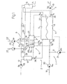
- a dialysis machine 1 comprises an extracorporeal blood circuit 2, a dialysis liquid circuit 3 and a filter 4 (dialyzer) having a blood compartment 5 and a dialysis liquid compartment 6 separated by a semi-permeable membrane 7.
- the extracorporeal blood circuit 2 comprises an arterial pipe 12 and a venous pipe 15, respectively connected to an inlet and an outlet of the blood compartment 5 of the filter 4.
- the arterial pipe 12 is fitted with a peristaltic pump 13 supplying a blood flow Q b and a bubble trap 14, and the venous pipe 15 is fitted with a bubble trap 16.
- the dialysis liquid circuit 3 comprises a supply pipe 17 and a drain pipe 18, respectively connected to an inlet and an outlet of the dialysis liquid compartment 6 of the filter 4.
- the supply pipe 17 is fitted with a pump 19 supplying a fresh dialysis liquid flow Q di and the drain pipe 18 is fitted with a pump 20 supplying a used liquid flow Q do .
- the upstream end of the supply pipe 17 is connected to a source of fresh dialysis liquid (not shown).
- An ultrafiltration pipe 8 is connected to the drain pipe 18 between the filter 4 and the pump 20 and is fitted with an ultrafiltration pump 21 supplying a flow UFR.
- An infusion pipe 9 is connected to the extracorporeal blood circuit 2. It comprises a main pipe 22, which forks into a pre-dilution pipe 25 connected to the arterial bubble trap 14 and a post-dilution pipe 26 connected to the venous bubble trap 16.
- the main pipe 9 is fitted with an infusion pump 23 supplying a flow IR.
- a valve set 24 is arranged directly downstream from the fork on the pre-dilution and post-dilution pipes 25, 26. In use, the upstream end of the main pipe 22 is connected to a source of sterile solution (not shown).
- a compressed air line 10 comprises a main pipe 27 which forks into two secondary pipes 29 and 30, respectively connected to the arterial and venous bubble traps 14, 15.
- a valve set 28 is arranged at the connection between the main and secondary air pipes.
- the control circuit 11 comprises a control unit 31, a sensor 32 positioned on the arterial pipe 12 directly upstream from the filter 4 for supplying a signal P bi correlated to the blood pressure at the inlet of the filter 4, a sensor 33 positioned on the venous pipe 15 directly downstream from the filter 4 for supplying a signal P bo correlated to the blood pressure at the outlet of the filter 4, a sensor 34 positioned on the supply pipe 17 for supplying a signal P di correlated to the pressure of the dialysis liquid at the inlet of the filter 4, and a sensor 35 positioned on the drain pipe 18 for supplying a signal P do correlated to the pressure of the dialysis liquid at the outlet of the filter 4.
- the control circuit 11 also comprises a haemoconcentration sensor 36 arranged along pipe 12 between the filter 4 and the bubble trap 14 for producing a haemoconcentration signal C E .
- the signals P bi , P bo , P di , P do and C E and the set values of various parameters, such as the blood flow rate Q b , the flow rates Q di and Q do of the dialysis liquid in the supply pipe 17 and in the drain pipe 18, the ultrafiltration flow rate UFR, and the infusion flow rate IR are received by the central unit 31 for controlling the operation of the machine 1.
- the central unit 31 emits output signals for controlling the valve sets 24 and 28, the ultrafiltration pump 21 and the infusion pump 23, as will be made clear in the rest of the description.
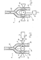
- the valve set 24 comprises a double-pinch valve 37 and an electromagnet 38 for operating the valve 37.
- the valve 37 is positioned on the infusion pipes 25 and 26 in a position where the pipes 25 and 26 are substantially parallel, and comprises two fixed and opposite members 39 and 40, which are arranged in contact with the pipes 25 and 26 respectively, and a movable member 41, which is positioned between the pipes 25 and 26 and between the fixed members 39 and 40.
- the movable element 41 is connected to a slide 42 of the electromagnet 38 and can move between a position of rest, shown by a solid line in figure 2, and two operating positions, shown by dashed lines in figure 2.
- the valve set 24 comprises a pinch valve 43, which comprises a cam-type movable member 44, which can rotate about an axis 45 and is caused to rotate by an electric stepping motor 46.
- Cam-member 43 occupies two positions of rest about axis 45, one of which is shown by a solid line in Fig. 3, and two operating positions, shown by dashed lines in Fig. 3.
- the infusion of liquid is regulated by adjusting the delivery, by the pump 23, of a liquid (generally a solution possessing physiological composition and concentration) upstream and downstream from the filter 4.
- a liquid generally a solution possessing physiological composition and concentration
- the machine 1 operates on the basis of studies undertaken by the applicant, which demonstrated that the occurrence of some critical conditions does not depend on the absolute value of the individual quantities being monitored, but on the amount of liquid removed by ultrafiltration with respect to the plasma flow at the filter inlet.
- the filtration factor is a quantity that is correlated with the concentration of the blood C E .
- the control unit 31 compares the filtration factor FF determined using the above equation with a series of intervals I 1...x , which are each associated with corresponding values of the respective signals S, G, H, L and A at the output of control unit 31.
- the central control unit 31 ascribes defined values to the corresponding output signals G, H, S and L for operating, respectively, the valve sets 24 and 28 and/or the ultrafiltration pump 21, and the infusion pump 23.
- control situation is shown schematically in figure 1 by the control signals G, H, S and L generated by the control unit 31 and acting respectively on the valve sets 24 and 28 and on the ultrafiltration pump 21 and the infusion pump 23, and by a signal A supplied to a display unit (not shown).
- each particular operating condition can comprise, in combination, a particular distribution of the infusion liquid in pre-dilution and in post-dilution by acting upon valve set 24, a variation of the ultrafiltration flow rate UFR by acting on the pump 21 and a variation of the infusion flow rate IR by acting on the pump 23.
- valve set 28 By adjusting the valve set 28 it is possible to change the amount of air inside the bubble traps 14 and 16 when there is a variation of the pre-dilution and post-dilution flow rates.
- the concentration of the blood C E can be measured directly, via the haematocrit Hct, or indirectly by measuring the haemoglobin (in which case the value of the haematocrit Hct is obtained by dividing the measured haemoglobin value Hgb by the cellular mean concentration of the haemoglobin Hcmc or by measurements of the viscosity, the electrical conductivity or the density of the blood, in a known manner which will not be described in detail).
- the signals S and L are for controlling the motors of the pumps 21 and 23 so as to increase or decrease the flow rates UFR and IR.
- the signal H is for controlling the valve set 28 and for determining the amount of air in the bubble traps 14 and 16 in relation to the pre-dilution and post-dilution flow rates.
- the signal G is a control signal for exciting the electromagnet 38 according to a predetermined sequence.
- the distribution of the infusion flow in the two pipes 25, 26 results from the alternate opening and closing of the pre-dilution and post-dilution pipes 25 and 26 by means of the movable member 41 operated by electromagnet 38 according to a sequence defined by signal G.
- control sequences comprise, in addition to the combined operating mode between pre-dilution and post-dilution, also the exclusive pre-dilution operating mode and the exclusive post-dilution operating mode.
- the movable member 41 is displaced alternately against the fixed members 39 and 40 so as to pinch the infusion pipes 25 and 26 alternately and so as to interrupt the infusion flow in pipes 25 and 26 cyclically and according to a defined sequence.
- the valve set 24 in figure 3 operates like the valve set in figure 2, so as to cause the alternation of the closed position of the pipes 25 and 26.
- the signal G defines a particular sequence of the angular position of the motor 46 which determines, in turn, the position of the movable member 44.
- TMP i is the transmembrane pressure value, which is equal to the difference between the pressure value P bi at the inlet of the blood compartment 5 and the pressure value P do at the outlet of the dialysis liquid compartment 6
- TMP o is the outlet transmembrane pressure value, which is equal to the difference between the pressure value P bo at the outlet of the blood compartment 5 and the pressure value P di at the inlet of the dialysis liquid compartment 6.
- the mean transmembrane values are compared with respective intervals IT 1...x , which are each associated with corresponding respective signals G, H, S and L for operating the valve sets 24 and 28, the ultrafiltration pump 21 and the infusion pump 23.
- the values of the actual permeability K uf are compared with respective intervals IK 1...x , which are each associated with corresponding respective signals G, H, L and S for operating the valve sets 24 and 28, the ultrafiltration pump 21 and the infusion pump 23.
- the method based on the filtration factor FF can be employed in combination either with the method based on the mean transmembrane values TMP ave , or with the method based on the permeability values K uf .
- the present method permits accurate regulation and distribution of the infusion flow rate IR. Moreover, since the present method is based on the monitoring of quantities that are directly correlated with the operating conditions of the filter 4, it immediately supplies the magnitude of the changes required, or at any rate greatly simplifies the determination of these changes, for the purpose of improving the filtration efficiency and avoiding critical situations.
- control unit 31 can be implemented with the unit, already provided, for controlling the dialysis treatment, and the quantities employed are already available or can easily be obtained by mathematical methods from the measured or imposed quantities.
Landscapes
- Health & Medical Sciences (AREA)
- Heart & Thoracic Surgery (AREA)
- Vascular Medicine (AREA)
- Animal Behavior & Ethology (AREA)
- Anesthesiology (AREA)
- Biomedical Technology (AREA)
- Hematology (AREA)
- Life Sciences & Earth Sciences (AREA)
- Engineering & Computer Science (AREA)
- General Health & Medical Sciences (AREA)
- Public Health (AREA)
- Veterinary Medicine (AREA)
- Urology & Nephrology (AREA)
- Cardiology (AREA)
- Emergency Medicine (AREA)
- External Artificial Organs (AREA)
Abstract
Description
- The present invention relates to an infusion control device for controlling infusion of a liquid in an extracorporeal blood circuit.
- As is well known, blood is composed of a liquid part called blood plasma and a corpuscular part formed by the blood cells, including, among others, the red blood cells. In cases of renal insufficiency, apart from the aforementioned components, the blood also contains metabolic waste (urea, creatinine) in excess which must be removed by means of a dialysis treatment effected by a dialysis machine.
- A dialysis machine generally comprises: a filter (dialyzer) comprising a blood compartment and a dialysis liquid compartment separated from one another by a semi-permeable membrane; an extracorporeal blood circuit, which is connected to the blood compartment of the filter; and a dialysis liquid circuit, which is connected to the dialysis liquid compartment of the filter.
- In use, the blood to be treated and a dialysis liquid respectively pass through these compartments, generally flowing in counter-current.
- During dialysis treatment, there is migration of metabolic waste from the blood compartment to the dialysis liquid compartment through the semipermeable membrane by diffusion. Metabolic waste is also transferred by convection, from the blood compartment to the dialysis liquid compartment, when ultrafiltration of plasma water is caused through the membrane in order that the patient lose a determined weight during the treatment.
- To increase the efficiency of dialysis treatment, it is also known to cause the ultrafiltration of large amounts of plasma water, so as to enhance the effects of transport of the undesirable waste by convection. The quantity of plasma water removed in excess relative to the desired final weight loss is compensated with a substitution liquid, which is infused into the extracorporeal blood circuit.
- The substitution liquid is infused either upstream from the filter (pre-dilution technique) or downstream from the filter (post-dilution technique). The infusion liquid generally consists of a solution with physiological composition and concentration.
- Both pre-dilution and post-dilution techniques have their respective advantages and disadvantages.
- In the post-dilution technique, the plasma water removed through the membrane is more concentrated than in the pre-dilution technique and, at equal flows, the treatment is more efficient.
- On the other hand, with the post-dilution technique, blood becomes more easily concentrated, which can slower the blood flow in the filter as well as the ultrafiltration of plasma water (through partial clogging of the filter itself), giving rise to the phenomenon called filter "caking". Consequently, the post-dilution technique permits extraction of a more limited quantity of plasma water than with the pre-dilution technique.
- With the pre-dilution technique, the critical conditions leading to "caking" are avoided and the ultrafiltration efficiency is increased. However, at equal flows, the pre-dilution technique is less efficient than the post-dilution technique.
- WO 98/50091 describes a device for controlling infusion of a liquid in an extracorporeal blood circuit, as in the preamble of claim 1.
- The aim of the present invention is to provide a device and a method for infusing a liquid into an extracorporeal blood circuit of a dialysis machine that do not have the drawbacks described above.
- According to the present invention, a dialysis machine comprises: a filter having a blood compartment and a dialysis liquid compartment separated by a semi-permeable membrane; an extracorporeal blood circuit having an arterial pipe connected to an inlet of the blood compartment and a venous pipe connected to an outlet of the blood compartment; a dialysis liquid circuit having a supply pipe connected to an inlet of the dialysis liquid compartment and a drain pipe connected to an outlet of the dialysis liquid compartment; an infusion circuit having a pre-dilution pipe connected to the arterial pipe and a post-dilution pipe connected to the venous pipe; means for varying the flow of an infusion liquid in the pre-dilution pipe and in the post-dilution pipe, and control means for controlling the flow varying means so that the flow of the infusion liquid in the pre-dilution pipe and the post-dilution pipe matches a determined sequence.
- The dialysis machine according to the invention may comprise one or more or the following features: the control means comprises means for determining the infusion sequence from at least one characteristic value (FF, TMPave, Kuf) correlated with the concentration of the blood (CE) and/or the filtration efficiency of the filter; the control means comprises means for comparing the characteristic value (FF, TMPave, Kuf) with a series of intervals (I1...x, IT1...x, IK1...x), each interval (I1...x, IT1...x, IK1...x) being associated with at least a predetermined control signal (S, G, H, L); the infusion varying means comprises a valve means for alternately occluding the pre-dilution pipe and the post-dilution pipe, and the predetermined control signal (G) defines a sequence for opening and closing the valve means; the infusion varying means comprises an infusion pump for circulating the infusion liquid, and the predetermined control signal (L) is for regulating the flow rate (IR) of liquid generated by the infusion pump; the dialysis machine comprises an ultrafiltration pump for causing ultrafiltration of plasma water through the membrane of the filter, and the predetermined control signal (S) is for regulating the flow rate (UFR) of liquid generated by the ultrafiltration pump; the dialysis machine comprises a bubble trap connected to the arterial pipe and a bubble trap connected to the venous pipe and means for injecting or withdrawing air into/from the bubble traps so as to adjust the level of liquid therein, and in the predetermined control signal (S) is for controlling the means for injecting or withdrawing air into/from the bubble traps; the dialysis machine comprises means for determining an ultrafiltration flow rate (UFR) of plasma water through the membrane of the filter, means for determining the haematocrit (Hct) at the inlet of the filter, and means for calculating the characteristic value as a filtration factor (FF) equal to UFR/ [Qb (1-Hct)]; the dialysis machine comprises means for measuring the blood pressure values (Pbo, Pbi) at the inlet and at the outlet of the blood compartment of the filter, means for measuring the dialysis liquid pressure values (Pdi, Pdo) at the inlet and at the outlet of the dialysis liquid compartment of the filter, means for calculating an inlet transmembrane pressure value (TMPi) as the difference between the pressure value (Pbi) at the inlet of the blood compartment and the pressure value (Pdo) at the outlet of the dialysis liquid compartment and an outlet transmembrane pressure value (TMPo) as the difference between the pressure value (Pbo) at the outlet of the blood compartment and the pressure value (Pdi) at the inlet of the dialysis liquid compartment, means for calculating the characteristic value as a mean transmembrane pressure value (TMPave) equal to [TMPi-TMPo] /2; the dialysis machine comprises means for determining a ultrafiltration flow rate (UFR) of plasma water through the membrane of the filter, means for calculating the characteristic value as an actual permeability (Kuf) equal to the ratio between the ultrafiltration flow rate (UFR) and the mean transmembrane pressure value (TMPave).
- Another object of the present invention is a method for infusing an infusion liquid into an extracorporeal blood circuit of a dialysis liquid machine, the extracorporeal blood circuit having an arterial pipe connected to an inlet of a blood compartment of a filter, and a venous pipe connected to an outlet of the blood compartment, the filter having a blood compartment and a dialysis liquid compartment separated by a semi-permeable membrane, characterized in that it comprises the steps of determining an infusion sequence from at least one characteristic value (FF, TMPave, Kuf) correlated with the concentration of the blood (CE) and/or a filtration efficiency of the filter, and infusing the infusion solution in either one or both of the arterial pipe and in the venous pipe in accordance with the determined infusion sequence.
- For better understanding of the present invention an embodiment thereof will now be described, referring to the appended drawings, in which:
- Figure 1 is a schematic representation of a dialysis machine;
- Figure 2 is a schematic representation of a detail of the machine of figure 1; and
- Figure 3 is a schematic representation of a variant of the detail in figure 2.
- In figure 1, a dialysis machine 1 comprises an
extracorporeal blood circuit 2, a dialysisliquid circuit 3 and a filter 4 (dialyzer) having a blood compartment 5 and a dialysis liquid compartment 6 separated by a semi-permeable membrane 7. - The
extracorporeal blood circuit 2 comprises anarterial pipe 12 and avenous pipe 15, respectively connected to an inlet and an outlet of the blood compartment 5 of the filter 4. Thearterial pipe 12 is fitted with aperistaltic pump 13 supplying a blood flow Qb and abubble trap 14, and thevenous pipe 15 is fitted with abubble trap 16. - The dialysis
liquid circuit 3 comprises asupply pipe 17 and adrain pipe 18, respectively connected to an inlet and an outlet of the dialysis liquid compartment 6 of the filter 4. Thesupply pipe 17 is fitted with apump 19 supplying a fresh dialysis liquid flow Qdi and thedrain pipe 18 is fitted with apump 20 supplying a used liquid flow Qdo. - In use, the upstream end of the
supply pipe 17 is connected to a source of fresh dialysis liquid (not shown). - An
ultrafiltration pipe 8 is connected to thedrain pipe 18 between the filter 4 and thepump 20 and is fitted with anultrafiltration pump 21 supplying a flow UFR. - An
infusion pipe 9 is connected to theextracorporeal blood circuit 2. It comprises amain pipe 22, which forks into apre-dilution pipe 25 connected to thearterial bubble trap 14 and apost-dilution pipe 26 connected to thevenous bubble trap 16. Themain pipe 9 is fitted with aninfusion pump 23 supplying a flow IR. Avalve set 24 is arranged directly downstream from the fork on the pre-dilution andpost-dilution pipes main pipe 22 is connected to a source of sterile solution (not shown). - A
compressed air line 10 comprises amain pipe 27 which forks into twosecondary pipes venous bubble traps valve set 28 is arranged at the connection between the main and secondary air pipes. - The
control circuit 11 comprises acontrol unit 31, asensor 32 positioned on thearterial pipe 12 directly upstream from the filter 4 for supplying a signal Pbi correlated to the blood pressure at the inlet of the filter 4, asensor 33 positioned on thevenous pipe 15 directly downstream from the filter 4 for supplying a signal Pbo correlated to the blood pressure at the outlet of the filter 4, asensor 34 positioned on thesupply pipe 17 for supplying a signal Pdi correlated to the pressure of the dialysis liquid at the inlet of the filter 4, and asensor 35 positioned on thedrain pipe 18 for supplying a signal Pdo correlated to the pressure of the dialysis liquid at the outlet of the filter 4. Thecontrol circuit 11 also comprises ahaemoconcentration sensor 36 arranged alongpipe 12 between the filter 4 and thebubble trap 14 for producing a haemoconcentration signal CE. - The signals Pbi, Pbo, Pdi, Pdo and CE and the set values of various parameters, such as the blood flow rate Qb, the flow rates Qdi and Qdo of the dialysis liquid in the
supply pipe 17 and in thedrain pipe 18, the ultrafiltration flow rate UFR, and the infusion flow rate IR are received by thecentral unit 31 for controlling the operation of the machine 1. - In practice, the
central unit 31 emits output signals for controlling thevalve sets ultrafiltration pump 21 and theinfusion pump 23, as will be made clear in the rest of the description. - Referring to figure 2, the
valve set 24 comprises a double-pinch valve 37 and anelectromagnet 38 for operating thevalve 37. Thevalve 37 is positioned on theinfusion pipes pipes opposite members pipes movable member 41, which is positioned between thepipes members movable element 41 is connected to aslide 42 of theelectromagnet 38 and can move between a position of rest, shown by a solid line in figure 2, and two operating positions, shown by dashed lines in figure 2. - According to the variant in figure 3, the
valve set 24 comprises apinch valve 43, which comprises a cam-typemovable member 44, which can rotate about anaxis 45 and is caused to rotate by anelectric stepping motor 46. Cam-member 43 occupies two positions of rest aboutaxis 45, one of which is shown by a solid line in Fig. 3, and two operating positions, shown by dashed lines in Fig. 3. - In use, the infusion of liquid is regulated by adjusting the delivery, by the
pump 23, of a liquid (generally a solution possessing physiological composition and concentration) upstream and downstream from the filter 4. - The machine 1 operates on the basis of studies undertaken by the applicant, which demonstrated that the occurrence of some critical conditions does not depend on the absolute value of the individual quantities being monitored, but on the amount of liquid removed by ultrafiltration with respect to the plasma flow at the filter inlet.
- Since the plasma flow depends on the blood flow Qb and on the initial concentration of the blood, according to one embodiment of the invention, the values of the blood flow Qb, the ultrafiltration flow rate UFR and the concentration of the blood CE are acquired; the filtration factor FF, defined below, is determined on the basis of these quantities:
control unit 31 compares the filtration factor FF determined using the above equation with a series of intervals I1...x, which are each associated with corresponding values of the respective signals S, G, H, L and A at the output ofcontrol unit 31. When the filtration factor FF is within a defined interval Ix, thecentral control unit 31 ascribes defined values to the corresponding output signals G, H, S and L for operating, respectively, thevalve sets ultrafiltration pump 21, and theinfusion pump 23. - This control situation is shown schematically in figure 1 by the control signals G, H, S and L generated by the
control unit 31 and acting respectively on thevalve sets ultrafiltration pump 21 and theinfusion pump 23, and by a signal A supplied to a display unit (not shown). - The control of the operating point of filter 4 also permits its optimization. In practice, for each interval I1...x, there is a corresponding particular operating condition of the machine 1; specifically each particular operating condition can comprise, in combination, a particular distribution of the infusion liquid in pre-dilution and in post-dilution by acting upon
valve set 24, a variation of the ultrafiltration flow rate UFR by acting on thepump 21 and a variation of the infusion flow rate IR by acting on thepump 23. By adjusting the valve set 28 it is possible to change the amount of air inside thebubble traps - The concentration of the blood CE can be measured directly, via the haematocrit Hct, or indirectly by measuring the haemoglobin (in which case the value of the haematocrit Hct is obtained by dividing the measured haemoglobin value Hgb by the cellular mean concentration of the haemoglobin Hcmc or by measurements of the viscosity, the electrical conductivity or the density of the blood, in a known manner which will not be described in detail).
- The signals S and L are for controlling the motors of the
pumps - The signal H is for controlling the valve set 28 and for determining the amount of air in the
bubble traps - Referring to figure 2, the signal G is a control signal for exciting the
electromagnet 38 according to a predetermined sequence. In other words, the distribution of the infusion flow in the twopipes post-dilution pipes movable member 41 operated byelectromagnet 38 according to a sequence defined by signal G. - The control sequences comprise, in addition to the combined operating mode between pre-dilution and post-dilution, also the exclusive pre-dilution operating mode and the exclusive post-dilution operating mode. The
movable member 41 is displaced alternately against the fixedmembers infusion pipes pipes - The valve set 24 in figure 3 operates like the valve set in figure 2, so as to cause the alternation of the closed position of the
pipes motor 46 which determines, in turn, the position of themovable member 44. - According to one variant of the invention, the pre-dilution and post-dilution positions together with the ultrafiltration flow rate UFR and the infusion flow rate IR are adjusted in relation to the mean transmembrane values:
- In this formula, TMPi is the transmembrane pressure value, which is equal to the difference between the pressure value Pbi at the inlet of the blood compartment 5 and the pressure value Pdo at the outlet of the dialysis liquid compartment 6, and TMPo is the outlet transmembrane pressure value, which is equal to the difference between the pressure value Pbo at the outlet of the blood compartment 5 and the pressure value Pdi at the inlet of the dialysis liquid compartment 6.
- Here also, the mean transmembrane values are compared with respective intervals IT1...x, which are each associated with corresponding respective signals G, H, S and L for operating the valve sets 24 and 28, the
ultrafiltration pump 21 and theinfusion pump 23. - According to another variant, pre-dilution and post-dilution positions together with the flow rates of ultrafiltration UFR and infusion IR are regulated in relation to the actual permeability values of the membrane, defined as:
- The values of the actual permeability Kuf are compared with respective intervals IK1...x, which are each associated with corresponding respective signals G, H, L and S for operating the valve sets 24 and 28, the
ultrafiltration pump 21 and theinfusion pump 23. - The techniques for determining the operating conditions of the filter 4 and the state of the membrane 7 can be applied individually as described above or in combination as described in the applicant's patent application T099000680 filed on 30 July 1999.
- The method based on the filtration factor FF can be employed in combination either with the method based on the mean transmembrane values TMPave, or with the method based on the permeability values Kuf.
- The advantages of the present method are clear from the above description. It is emphasized, in particular, that the present method permits accurate regulation and distribution of the infusion flow rate IR. Moreover, since the present method is based on the monitoring of quantities that are directly correlated with the operating conditions of the filter 4, it immediately supplies the magnitude of the changes required, or at any rate greatly simplifies the determination of these changes, for the purpose of improving the filtration efficiency and avoiding critical situations.
- Furthermore, the present method does not require modification of the dialysis machine, since the
control unit 31 can be implemented with the unit, already provided, for controlling the dialysis treatment, and the quantities employed are already available or can easily be obtained by mathematical methods from the measured or imposed quantities.
Claims (22)
- Infusion control device for controlling infusion of a liquid in an extracorporeal blood circuit,
said extracorporeal blood circuit having:said infusion control device comprising a control unit (31) for permitting an accurate regulation and distribution of an infusion flow rate (IR) in said two pipes (25 and 26),an arterial pipe (12) connected to an inlet of a blood compartment (5) of a filter (4), said arterial pipe (12) being also connected to a pre-dilution pipe (25) of an infusion circuit,a venous pipe (15) connected to an outlet of said blood compartment (5), said venous pipe (15) being also connected to a post-dilution pipe (26) of said infusion circuit,
characterized in that said control unit (31) permits said accurate regulation and distribution based on a monitoring of quantities (TMP, FF, Kuf) that are directly correlated with the operating conditions of said filter (4). - Device according to claim 1, characterized in that said monitored quantities (TMP, FF, Kuf) employed are obtained by mathematical methods from measured quantities (Pbi, Pbo, Pdi, Pdo) or from imposed quantities or from measured and imposed quantities (Pbi, Pbo, Pdi, Pdo, Hct, UFR, Qb).
- Device according to claim 1 or 2, characterized in that said monitored quantities comprise trans-membrane pressure (TMP) values.
- Device according to claim 3, characterized in that said trans-membrane pressure (TMP) values include mean transmembrane values:
- Device according to claim 4, characterized in that it comprises:means (32, 33) for measuring the blood pressure values (Pbo, Pbi) at the inlet and at the outlet of the blood compartment (5) of the filter (4);means (34, 35) for measuring the dialysis liquid pressure values (Pdi, Pdo) at the inlet and at the outlet of the dialysis liquid compartment (6) of the filter (4);means (31) for calculating an inlet transmembrane pressure value (TMPi) as the difference between the pressure value (Pbi) at the inlet of the blood compartment (5) and the pressure value (Pdo) at the outlet of the dialysis liquid compartment (6) and an outlet transmembrane pressure value (TMPo) as the difference between the pressure value (Pbo) at the outlet of the blood compartment (5) and the pressure value (Pdi) at the inlet of the dialysis liquid compartment (6);means (31) for calculating mean transmembrane pressure value (TMPave) equal to [TMPi-TMPo]/2.
- Device according to any one of claims 1 to 5, characterized in that said monitored quantities comprise a quantity (FF) that is correlated with the concentration of the blood (CE).
- Device according to any one of claims 1 to 6, characterized in that said monitored quantities comprise a filtration factor (FF) determined on the basis of these quantities:
- Device according to claim 7, characterized in that it comprises:means for determining an ultrafiltration flow rate (UFR) of plasma water through the membrane (7) of the filter (4);means (11) for determining the hematocrit (Hct) at the inlet of the filter (4), andmeans (31) for calculating a filtration factor (FF) equal to UFR/[Qb(1-Hct)].
- Device according to claim 8, characterized in that the means for determining the hematocrit (Hct) comprises means for determining the hemoglobin concentration (11) at the inlet of the filter (4) and means (31) for dividing the hemoglobin concentration by a constant coefficient.
- Device according to any one of claims 1 to 9, characterized in that said monitored quantities comprise an actual permeability (Kuf) of a membrane of the filter (4).
- Device according to claim 10, characterized in that it comprises:means for determining an ultrafiltration flow rate (UFR) of plasma water through the membrane of the filter (4);means (31) for calculating an actual permeability (Kuf) of the membrane equal to the ratio between the ultrafiltration flow rate (UFR) and the mean transmembrane pressure value (TMPave).
- Infusion control device for controlling infusion of a liquid in an extracorporeal blood circuit, preferably according to any one of claims 1 to 11,
said extracorporeal blood circuit having:said infusion control device comprising control means (31) for regulating the flow rates in said two pipes (25 and 26) from at least one quantity (TMP, FF, Kuf) correlated with the concentration of the blood (CE) and/or with the filtration efficiency of the filter (4).an arterial pipe (12) connected to an inlet of a blood compartment (5) of a filter (4), the arterial pipe (12) being also connected to a pre-dilution pipe (25) of an infusion circuit,a venous pipe (15) connected to an outlet of the blood compartment (5), the venous pipe (15) being also connected to a post-dilution pipe (26) of said infusion circuit, - Device according to claim 12, characterized in that said at least one quantity (TMP, FF, Kuf) comprises at least one selected in the group including:a filtration factor (FF) determined on the basis of:an actual permeability (Kuf) of a membrane of the filter (4);a trans-membrane pressure (TMP) of a membrane of the filter (4).
- Device according to any one of claims 1 to 13, characterized in that it comprises a valve means for alternately occluding the pre-dilution pipe (25) and the post-dilution pipe (26).
- Device according to any one of claims 1 to 14, comprising at least one infusion pump for circulating an infusion liquid in said pre-dilution (25) and post-dilution pipes (26).
- An infusion control device for controlling infusion of a liquid in an extracorporeal blood circuit, preferably according to any one of claims 1 to 15,
said extracorporeal blood circuit comprising:said infusion control device comprising:an arterial pipe (12) connected to an inlet of a blood compartment (5) of a filter (4), the arterial pipe (12) being also connected to a pre-dilution pipe (25) of an infusion circuit,a venous pipe (15) connected to an outlet of the blood compartment (5), the venous pipe (15) being also connected to a post-dilution pipe (26) of said infusion circuit,sensors (32, 33, 34, 35, 36) able to emit signals correlated to at least one quantity (Pbi, Pbo, Pdi, Pdo, CE) correlated with the concentration of the blood (CE) and/or with the filtration efficiency of the filter (4);a control unit (31) able to receive said signals and to regulate the infusion flow rates in the pre-dilution pipe (25) and in the post-dilution pipe (26) on the basis of at least one characteristic value (TMP, FF, Kuf) obtained from said signals. - Device according to claim 16, characterized in that said sensors are selected in the group including: haemoconcentration sensors, blood viscosity measuring devices, blood electrical conductivity measuring devices, blood density measuring devices, blood pressure sensors and dialysis liquid pressure sensors.
- Device according to claim 16 or 17, characterized in that said at least one characteristic value (TMP, FF, Kuf) comprises at least one selected in the group including:a filtration factor determined on the basis of:an actual permeability (Kuf) of a membrane of the filter (4);a trans-membrane pressure (TMP) of a membrane of the filter (4).
- Dialysis machine comprising an infusion control device as in any one of claims 1 to 17.
- Control unit for controlling the operation of a dialysis machine,
said dialysis machine comprising:characterized in that said control unit (31) is programmed for carrying out the following steps:a filter (4),an extracorporeal blood circuit (2) having:an arterial pipe (12) connected to an inlet of a blood compartment (5) of said filter (4), said arterial pipe (12) being also connected to a pre-dilution pipe (25) of an infusion circuit,a venous pipe (15) connected to an outlet of said blood compartment (5), said venous pipe (15) being also connected to a post-dilution pipe (26) of said infusion circuit,sensors (32, 33, 34, 35, 36) for monitoring at least one quantity (FF, TMP, Kuf) directly correlated with the operating conditions of said filter (4),receiving signals from said sensors (32, 33, 34, 35, 36);controlling distribution of an infusion flow in said pre-dilution pipe (25) and in said post-dilution pipe (26) based on said at least one monitored quantity. - Control unit according to claim 20, characterized in that said at least one monitored quantity (FF, TMP, Kuf) is correlated with the concentration of the blood (CE) and/or with the filtration efficiency of said filter (4).
- Control unit according to claim 20 or 21, characterized in that it comprises at least one calculating means selected in the group comprising:means for calculating a filtration factor determined on the basis of:means for calculating an actual permeability (Kuf) of a membrane of the filter (4);means for calculating a trans-membrane pressure (TMP) of a membrane of the filter (4).
Applications Claiming Priority (3)
| Application Number | Priority Date | Filing Date | Title |
|---|---|---|---|
| ITTO20000333 | 2000-04-07 | ||
| IT2000TO000333A IT1320024B1 (en) | 2000-04-07 | 2000-04-07 | METHOD FOR ADJUSTING THE INFUSION IN A DIALYSIS MACHINE AND DIALYSIS MACHINE FOR THE APPLICATION OF THE MENTIONED METHOD. |
| EP01915621A EP1200141B2 (en) | 2000-04-07 | 2001-04-02 | Dialysis machine |
Related Parent Applications (2)
| Application Number | Title | Priority Date | Filing Date |
|---|---|---|---|
| EP01915621A Division EP1200141B2 (en) | 2000-04-07 | 2001-04-02 | Dialysis machine |
| EP01915621.5 Division | 2001-04-02 |
Publications (3)
| Publication Number | Publication Date |
|---|---|
| EP1424089A2 true EP1424089A2 (en) | 2004-06-02 |
| EP1424089A3 EP1424089A3 (en) | 2004-07-21 |
| EP1424089B1 EP1424089B1 (en) | 2011-08-31 |
Family
ID=11457656
Family Applications (3)
| Application Number | Title | Priority Date | Filing Date |
|---|---|---|---|
| EP05019650.0A Expired - Lifetime EP1604699B1 (en) | 2000-04-07 | 2001-04-02 | Device and method for controlling infusion of a liquid in an extracorporeal blood circuit |
| EP01915621A Expired - Lifetime EP1200141B2 (en) | 2000-04-07 | 2001-04-02 | Dialysis machine |
| EP04003132A Expired - Lifetime EP1424089B1 (en) | 2000-04-07 | 2001-04-02 | Dialysis machine |
Family Applications Before (2)
| Application Number | Title | Priority Date | Filing Date |
|---|---|---|---|
| EP05019650.0A Expired - Lifetime EP1604699B1 (en) | 2000-04-07 | 2001-04-02 | Device and method for controlling infusion of a liquid in an extracorporeal blood circuit |
| EP01915621A Expired - Lifetime EP1200141B2 (en) | 2000-04-07 | 2001-04-02 | Dialysis machine |
Country Status (9)
| Country | Link |
|---|---|
| US (2) | US6730233B2 (en) |
| EP (3) | EP1604699B1 (en) |
| AT (2) | ATE305318T1 (en) |
| AU (1) | AU774113B2 (en) |
| CA (1) | CA2372307C (en) |
| DE (1) | DE60113624T3 (en) |
| ES (3) | ES2250366T5 (en) |
| IT (1) | IT1320024B1 (en) |
| WO (1) | WO2001076661A1 (en) |
Cited By (4)
| Publication number | Priority date | Publication date | Assignee | Title |
|---|---|---|---|---|
| WO2011113602A1 (en) * | 2010-03-19 | 2011-09-22 | Fresenius Medical Care Deutschland Gmbh | Device for regulating at least one filtration value, haemodialysis machine and corresponding method and use |
| WO2015086189A1 (en) | 2013-12-11 | 2015-06-18 | Gambro Lundia Ab | Extracorporeal blood treatment system, disposable set and valve unit for pre/post infusion. |
| IT201700052603A1 (en) * | 2017-05-16 | 2018-11-16 | Medica S P A | FILTERING SYSTEM FOR CONTINUOUS RENAL SUBSTITUTE THERAPIES |
| IT201900002233A1 (en) * | 2019-02-15 | 2020-08-15 | Medica S P A | FILTERING SYSTEM FOR CONTINUOUS KIDNEY REPLACEMENT THERAPIES |
Families Citing this family (58)
| Publication number | Priority date | Publication date | Assignee | Title |
|---|---|---|---|---|
| US8105258B2 (en) | 1999-04-26 | 2012-01-31 | Baxter International Inc. | Citrate anticoagulation system for extracorporeal blood treatments |
| BR9902607B1 (en) * | 1999-06-23 | 2010-08-24 | biomass pre-hydrolysis apparatus and process. | |
| IT1310659B1 (en) * | 1999-07-30 | 2002-02-19 | Hospal Dasco Spa | METHOD OF CONTROL OF A DIALYSIS MACHINE WITH A SEMI-PERMANENT FILTER. |
| DK1175917T3 (en) † | 2000-07-07 | 2008-01-07 | Fresenius Medical Care De Gmbh | hemodialysis |
| US20030010718A1 (en) | 2001-07-12 | 2003-01-16 | Nxstage Medical, Inc. | Hemodilution cap and methods of use in blood-processing procedures |
| US6796955B2 (en) * | 2002-02-14 | 2004-09-28 | Chf Solutions, Inc. | Method to control blood and filtrate flowing through an extracorporeal device |
| US7052480B2 (en) | 2002-04-10 | 2006-05-30 | Baxter International Inc. | Access disconnection systems and methods |
| US7022098B2 (en) | 2002-04-10 | 2006-04-04 | Baxter International Inc. | Access disconnection systems and methods |
| US20040254513A1 (en) | 2002-04-10 | 2004-12-16 | Sherwin Shang | Conductive polymer materials and applications thereof including monitoring and providing effective therapy |
| US10155082B2 (en) | 2002-04-10 | 2018-12-18 | Baxter International Inc. | Enhanced signal detection for access disconnection systems |
| DE10230413B4 (en) * | 2002-07-06 | 2004-07-22 | Fresenius Medical Care Deutschland Gmbh | Device for determining the blood volume during extracorporeal blood treatment |
| JP3958733B2 (en) * | 2002-11-14 | 2007-08-15 | 日機装株式会社 | Blood purification equipment |
| US7314554B2 (en) * | 2003-02-07 | 2008-01-01 | Gambro Lundia Ab | Extracorporeal blood treatment machine |
| ITMI20030212A1 (en) * | 2003-02-07 | 2004-08-08 | Gambro Lundia Ab | METHOD FOR EXTRA-BODY BLOOD TREATMENT |
| US7291269B2 (en) * | 2003-03-17 | 2007-11-06 | Gambro Lundia Ab | Apparatus and process for extracorporeal treatment of blood with selective extraction of solutes |
| US7744553B2 (en) * | 2003-12-16 | 2010-06-29 | Baxter International Inc. | Medical fluid therapy flow control systems and methods |
| US20060009727A1 (en) * | 2004-04-08 | 2006-01-12 | Chf Solutions Inc. | Method and apparatus for an extracorporeal control of blood glucose |
| US8323194B2 (en) * | 2009-12-18 | 2012-12-04 | Inlight Solutions, Inc. | Detection of bubbles during hemodynamic monitoring when performing automated measurement of blood constituents |
| US20100168535A1 (en) * | 2006-04-12 | 2010-07-01 | Mark Ries Robinson | Methods and apparatuses related to blood analyte measurement system |
| WO2007059476A2 (en) * | 2005-11-15 | 2007-05-24 | Luminous Medical, Inc. | Blood analyte determinations |
| US20090088615A1 (en) * | 2007-10-01 | 2009-04-02 | Mark Ries Robinson | Indwelling Fiber Optic Probe for Blood Glucose Measurements |
| US20090156975A1 (en) * | 2007-11-30 | 2009-06-18 | Mark Ries Robinson | Robust System and Methods for Blood Access |
| US20090048535A1 (en) * | 2007-08-13 | 2009-02-19 | Mark Ries Robinson | Detecting Cross-contamination in Blood Measurements with a Multilumen Catheter |
| US20090054754A1 (en) * | 2007-08-21 | 2009-02-26 | Mcmahon Dave | Clinician-controlled semi-automated medication management |
| US20100094114A1 (en) * | 2008-10-09 | 2010-04-15 | Mark Ries Robinson | Use of multiple calibration solutions with an analyte sensor with use in an automated blood access system |
| US7815809B2 (en) * | 2005-12-13 | 2010-10-19 | Gambro Lundia Ab | Method for conductivity calculation in a treatment fluid upstream and downstream a filtration unit in apparatuses for the blood treatment |
| US7713226B2 (en) * | 2006-01-06 | 2010-05-11 | Renal Solutions, Inc. | On demand and post-treatment delivery of saline to a dialysis patient |
| CN101378797B (en) † | 2006-02-07 | 2013-08-07 | 株式会社Jms | Blood purification apparatus and blood purification circuit |
| US8114276B2 (en) * | 2007-10-24 | 2012-02-14 | Baxter International Inc. | Personal hemodialysis system |
| JP5559060B2 (en) * | 2007-12-22 | 2014-07-23 | フレセニウス・メディカル・ケア・ドイチュラント・ゲーエムベーハー | Method and device for determining membrane permeation pressure in extracorporeal blood treatment |
| US8114043B2 (en) | 2008-07-25 | 2012-02-14 | Baxter International Inc. | Electromagnetic induction access disconnect sensor |
| US20100237011A1 (en) * | 2009-03-20 | 2010-09-23 | Edward Allan Ross | Blood treatment systems and related methods |
| US8685251B2 (en) * | 2009-12-05 | 2014-04-01 | Home Dialysis Plus, Ltd. | Ultra-pasteurization for dialysis machines |
| WO2011063906A1 (en) | 2009-11-26 | 2011-06-03 | Fresenius Medical Care Deutschland Gmbh | Method for regulating the supply of substituate during extracorporeal blood treatment and extracorporeal blood treatment device comprising a unit for regulating the supply of substituate |
| US20110189048A1 (en) * | 2009-12-05 | 2011-08-04 | Curtis James R | Modular dialysis system |
| US8753515B2 (en) | 2009-12-05 | 2014-06-17 | Home Dialysis Plus, Ltd. | Dialysis system with ultrafiltration control |
| US8529491B2 (en) * | 2009-12-31 | 2013-09-10 | Fresenius Medical Care Holdings, Inc. | Detecting blood flow degradation |
| DE102010003642A1 (en) * | 2010-03-15 | 2011-09-15 | Fresenius Medical Care Deutschland Gmbh | Cassette with a sensor for determining the difference between a first and a second liquid flow |
| EP2558142B1 (en) | 2010-04-14 | 2016-08-17 | Fresenius Medical Care Deutschland GmbH | Device and method for monitoring the connection of a blood treatment unit to the liquid system of an extracorporeal blood treatment device |
| DE102010032154A1 (en) * | 2010-07-23 | 2012-01-26 | Fresenius Medical Care Deutschland Gmbh | Device for monitoring connection of blood treatment unit to liquid system of extracorporeal blood treatment device, has mediums for measuring pressure in one line section or another line section of line system |
| US8501009B2 (en) | 2010-06-07 | 2013-08-06 | State Of Oregon Acting By And Through The State Board Of Higher Education On Behalf Of Oregon State University | Fluid purification system |
| EP2433662B1 (en) | 2010-09-27 | 2014-06-04 | Gambro Lundia AB | Apparatus for extracorporeal treatment of blood |
| US8840790B2 (en) | 2011-04-27 | 2014-09-23 | Fenwal, Inc. | Systems and methods of controlling fouling during a filtration procedure |
| EP3799897A1 (en) | 2011-08-30 | 2021-04-07 | Gambro Lundia AB | Apparatus for extracorporeal treatment of blood |
| ES2640953T3 (en) | 2011-10-07 | 2017-11-07 | Outset Medical, Inc. | Purification of heat exchange fluid for a dialysis system |
| US20130146541A1 (en) | 2011-12-13 | 2013-06-13 | Nxstage Medical, Inc. | Fluid purification methods, devices, and systems |
| US9433721B2 (en) | 2013-06-25 | 2016-09-06 | Fresenius Medical Care Holdings, Inc. | Vial spiking assemblies and related methods |
| ES2864727T3 (en) | 2014-04-29 | 2021-10-14 | Outset Medical Inc | Dialysis system and methods |
| CN104383618B (en) * | 2014-12-03 | 2017-02-22 | 北京迈淩医疗技术发展有限公司 | Hemodialysis filter allowing simultaneous front and back liquid supplementing |
| US9974942B2 (en) | 2015-06-19 | 2018-05-22 | Fresenius Medical Care Holdings, Inc. | Non-vented vial drug delivery |
| JP7025408B2 (en) | 2016-08-19 | 2022-02-24 | アウトセット・メディカル・インコーポレイテッド | Peritoneal dialysis system and method |
| US10881347B2 (en) | 2017-12-29 | 2021-01-05 | Fresenius Medical Care Holdings, Inc. | Closed loop dialysis treatment using adaptive ultrafiltration rates |
| JP7098433B2 (en) * | 2018-06-20 | 2022-07-11 | 日機装株式会社 | Plasma flow rate acquisition method using blood purification device and blood purification device |
| JP7144979B2 (en) * | 2018-06-20 | 2022-09-30 | 日機装株式会社 | Blood purification device and method for estimating patient's nutritional status by blood purification device |
| US11419969B2 (en) | 2019-03-26 | 2022-08-23 | Nuwellis, Inc. | Neonatal and pediatric blood filtration system |
| DE102019124990A1 (en) | 2019-09-17 | 2021-03-18 | B.Braun Avitum Ag | Blood treatment device with automatic reduction of a substitution solution flow rate |
| US20230363981A1 (en) * | 2021-08-18 | 2023-11-16 | Alcor Scientific, Inc. | Enteral feeding pump systems, valve assemblies therefor and fluid flow control methods for same |
| US11896798B2 (en) | 2021-08-18 | 2024-02-13 | Alcor Scientific, Inc. | Enteral feeding pump systems, valve assemblies therefor and fluid flow control methods for same |
Citations (2)
| Publication number | Priority date | Publication date | Assignee | Title |
|---|---|---|---|---|
| WO1998050091A1 (en) | 1997-05-07 | 1998-11-12 | Infomed S.A. | Method for controlling a blood purifying device |
| WO2001032238A2 (en) | 1999-10-29 | 2001-05-10 | Infomed S.A. | Extracorporeal blood purification device |
Family Cites Families (18)
| Publication number | Priority date | Publication date | Assignee | Title |
|---|---|---|---|---|
| DD157952A3 (en) * | 1980-08-13 | 1982-12-22 | Wolfgang Simon | DEVICE FOR EXTRACORPORAL TREATMENT OF BLOOD |
| EP0343247B1 (en) * | 1987-07-30 | 1993-03-03 | Toray Industries, Inc. | Porous polytetrafluoroethylene membrane, separating apparatus using same, and process for their production |
| US5032274A (en) * | 1988-05-04 | 1991-07-16 | Millipore Corporation | Process for producing fluorocarbon membranes and membrane product |
| US4990294A (en) * | 1988-05-04 | 1991-02-05 | Millipore Corporation | Process for producing fluorocarbon membranes and membrane product |
| US4902456A (en) * | 1988-05-04 | 1990-02-20 | Millipore Corporation | Fluorocarbon membranes and process for making fluorocarbon membranes |
| US4906377A (en) * | 1988-05-04 | 1990-03-06 | Millipore Corporation | Fluorocarbon membranes and process for making fluorocarbon membranes |
| US5154817A (en) * | 1990-05-24 | 1992-10-13 | Betz Laboratories, Inc. | Method for inhibiting gum and sediment formation in liquid hydrocarbon mediums |
| US6471872B2 (en) * | 1991-10-11 | 2002-10-29 | Children's Hospital Medical Center | Hemofiltration system and method based on monitored patient parameters |
| US5855783A (en) * | 1991-11-15 | 1999-01-05 | Memtec America Corporation | Pleated poly(tetra-fluoro ethylene) filter cartridge |
| US5490931A (en) * | 1992-02-24 | 1996-02-13 | Hoechst Celanese Corp. | Fabrication of a fluoropolymer hollow fiber having a defect-free separation layer |
| DE4240681C2 (en) * | 1992-12-03 | 1994-09-08 | Fresenius Ag | Device for hemodialysis without anticoagulation |
| US5910252A (en) * | 1993-02-12 | 1999-06-08 | Cobe Laboratories, Inc. | Technique for extracorporeal treatment of blood |
| US5695702A (en) * | 1994-07-01 | 1997-12-09 | Millipore Corporation | Thermoplastic hollow fiber membrane module and method of manufacture |
| US5762789A (en) * | 1996-06-28 | 1998-06-09 | Millipore Corporation | Disposable membrane module with low-dead volume |
| DE19654746C2 (en) | 1996-12-30 | 2000-05-11 | Klaus Sodemann | Dialysis solution |
| WO2000009182A1 (en) * | 1998-08-11 | 2000-02-24 | Alpamed S.A. | Fluid driving device |
| FR2800618B1 (en) * | 1999-11-08 | 2002-02-22 | Bert Christophe | HEMO-FILTRATION APPARATUS FOR INDEPENDENTLY CONTROLLING THE CONCENTRATION OF AT LEAST TWO IONIC SUBSTANCES IN THE INTERIOR OF A PATIENT |
| US6635026B1 (en) * | 1999-11-08 | 2003-10-21 | Hospal Industrie | Haemofiltration machine for independently controlling the concentration of a least two ionic substances in a patient's internal medium |
-
2000
- 2000-04-07 IT IT2000TO000333A patent/IT1320024B1/en active
-
2001
- 2001-04-02 ES ES01915621T patent/ES2250366T5/en not_active Expired - Lifetime
- 2001-04-02 CA CA002372307A patent/CA2372307C/en not_active Expired - Lifetime
- 2001-04-02 ES ES05019650.0T patent/ES2498954T3/en not_active Expired - Lifetime
- 2001-04-02 EP EP05019650.0A patent/EP1604699B1/en not_active Expired - Lifetime
- 2001-04-02 EP EP01915621A patent/EP1200141B2/en not_active Expired - Lifetime
- 2001-04-02 DE DE60113624T patent/DE60113624T3/en not_active Expired - Lifetime
- 2001-04-02 AT AT01915621T patent/ATE305318T1/en not_active IP Right Cessation
- 2001-04-02 US US09/980,864 patent/US6730233B2/en not_active Expired - Lifetime
- 2001-04-02 AT AT04003132T patent/ATE522239T1/en not_active IP Right Cessation
- 2001-04-02 WO PCT/IB2001/000544 patent/WO2001076661A1/en active IP Right Grant
- 2001-04-02 EP EP04003132A patent/EP1424089B1/en not_active Expired - Lifetime
- 2001-04-02 AU AU42701/01A patent/AU774113B2/en not_active Expired
- 2001-04-02 ES ES04003132T patent/ES2372385T3/en not_active Expired - Lifetime
-
2004
- 2004-02-06 US US10/772,340 patent/US6966979B2/en not_active Expired - Lifetime
Patent Citations (2)
| Publication number | Priority date | Publication date | Assignee | Title |
|---|---|---|---|---|
| WO1998050091A1 (en) | 1997-05-07 | 1998-11-12 | Infomed S.A. | Method for controlling a blood purifying device |
| WO2001032238A2 (en) | 1999-10-29 | 2001-05-10 | Infomed S.A. | Extracorporeal blood purification device |
Cited By (9)
| Publication number | Priority date | Publication date | Assignee | Title |
|---|---|---|---|---|
| WO2011113602A1 (en) * | 2010-03-19 | 2011-09-22 | Fresenius Medical Care Deutschland Gmbh | Device for regulating at least one filtration value, haemodialysis machine and corresponding method and use |
| CN102869395A (en) * | 2010-03-19 | 2013-01-09 | 弗雷森纽斯医疗护理德国有限责任公司 | Device for regulating at least one filtration value, haemodialysis machine and corresponding method and use |
| CN102869395B (en) * | 2010-03-19 | 2017-04-12 | 弗雷森纽斯医疗护理德国有限责任公司 | Device for regulating at least one filtration value, haemodialysis machine and corresponding method and use |
| US10201646B2 (en) | 2010-03-19 | 2019-02-12 | Fresenius Medical Care Deutschland Gmbh | Device for regulating at least one filtration value, haemodialysis machine and corresponding method and use |
| WO2015086189A1 (en) | 2013-12-11 | 2015-06-18 | Gambro Lundia Ab | Extracorporeal blood treatment system, disposable set and valve unit for pre/post infusion. |
| US10357600B2 (en) | 2013-12-11 | 2019-07-23 | Gambro Lundia Ab | Extracorporeal blood treatment system, disposable set and valve unit for pre/post infusion |
| IT201700052603A1 (en) * | 2017-05-16 | 2018-11-16 | Medica S P A | FILTERING SYSTEM FOR CONTINUOUS RENAL SUBSTITUTE THERAPIES |
| WO2018211434A1 (en) * | 2017-05-16 | 2018-11-22 | Medica S.P.A. | Filtering system for continuous renal replacement therapies |
| IT201900002233A1 (en) * | 2019-02-15 | 2020-08-15 | Medica S P A | FILTERING SYSTEM FOR CONTINUOUS KIDNEY REPLACEMENT THERAPIES |
Also Published As
| Publication number | Publication date |
|---|---|
| ES2372385T3 (en) | 2012-01-19 |
| EP1200141B1 (en) | 2005-09-28 |
| US6730233B2 (en) | 2004-05-04 |
| US6966979B2 (en) | 2005-11-22 |
| ES2498954T3 (en) | 2014-09-26 |
| ATE522239T1 (en) | 2011-09-15 |
| AU4270101A (en) | 2001-10-23 |
| CA2372307C (en) | 2009-02-10 |
| AU774113B2 (en) | 2004-06-17 |
| ATE305318T1 (en) | 2005-10-15 |
| EP1604699B1 (en) | 2014-07-02 |
| US20020121471A1 (en) | 2002-09-05 |
| EP1424089A3 (en) | 2004-07-21 |
| DE60113624T2 (en) | 2006-06-22 |
| ITTO20000333A1 (en) | 2001-10-07 |
| DE60113624T3 (en) | 2011-05-19 |
| EP1604699A2 (en) | 2005-12-14 |
| WO2001076661A1 (en) | 2001-10-18 |
| US20040154967A1 (en) | 2004-08-12 |
| CA2372307A1 (en) | 2001-10-18 |
| EP1200141A1 (en) | 2002-05-02 |
| EP1424089B1 (en) | 2011-08-31 |
| IT1320024B1 (en) | 2003-11-12 |
| ITTO20000333A0 (en) | 2000-04-07 |
| ES2250366T3 (en) | 2006-04-16 |
| ES2250366T5 (en) | 2011-04-08 |
| EP1604699A3 (en) | 2008-06-04 |
| DE60113624D1 (en) | 2006-02-09 |
| EP1200141B2 (en) | 2010-11-17 |
Similar Documents
| Publication | Publication Date | Title |
|---|---|---|
| EP1200141B1 (en) | Dialysis machine | |
| EP1351756B1 (en) | Multistage hemodiafiltration/hemofiltration apparatus | |
| JP6388166B2 (en) | Apparatus and method for adjusting a therapeutic instrument | |
| EP2280748B1 (en) | A hemodialysis or hemo(dia)filtration apparatus | |
| US9220830B2 (en) | Apparatus for extracorporeal blood treatment | |
| US9925321B2 (en) | Apparatus for extracorporeal blood treatment | |
| JP2004512873A (en) | Two-stage diafiltration method and apparatus | |
| US10940256B2 (en) | Hemodialysis system | |
| CN110225772A (en) | Device for extracorporeal blood treatment | |
| CN110392585A (en) | Device for extracorporeal blood treatment | |
| US10569001B2 (en) | Device and method for determining an optimum dialysate flow for an extracorporeal blood treatment with an extracorporeal blood treatment device | |
| US10307526B2 (en) | Device and method for regulating a treatment device | |
| CN113260391A (en) | Device for extracorporeal blood treatment |
Legal Events
| Date | Code | Title | Description |
|---|---|---|---|
| PUAI | Public reference made under article 153(3) epc to a published international application that has entered the european phase |
Free format text: ORIGINAL CODE: 0009012 |
|
| 17P | Request for examination filed |
Effective date: 20040213 |
|
| AC | Divisional application: reference to earlier application |
Ref document number: 1200141 Country of ref document: EP Kind code of ref document: P |
|
| AK | Designated contracting states |
Kind code of ref document: A2 Designated state(s): AT BE CH CY DE DK ES FI FR GB GR IE IT LI LU MC NL PT SE TR |
|
| PUAL | Search report despatched |
Free format text: ORIGINAL CODE: 0009013 |
|
| AK | Designated contracting states |
Kind code of ref document: A3 Designated state(s): AT BE CH CY DE DK ES FI FR GB GR IE IT LI LU MC NL PT SE TR |
|
| RIC1 | Information provided on ipc code assigned before grant |
Ipc: 7A 61M 1/16 B Ipc: 7A 61M 1/34 A |
|
| 17Q | First examination report despatched |
Effective date: 20050224 |
|
| AKX | Designation fees paid |
Designated state(s): AT BE CH CY DE DK ES FI FR GB GR IE IT LI LU MC NL PT SE TR |
|
| 111Z | Information provided on other rights and legal means of execution |
Free format text: AT BE CH CY DE DK ES FI FR GB GR IE IT LU MC NL PT SE TR Effective date: 20090504 |
|
| RTI1 | Title (correction) |
Free format text: DIALYSIS MACHINE |
|
| GRAP | Despatch of communication of intention to grant a patent |
Free format text: ORIGINAL CODE: EPIDOSNIGR1 |
|
| GRAS | Grant fee paid |
Free format text: ORIGINAL CODE: EPIDOSNIGR3 |
|
| GRAA | (expected) grant |
Free format text: ORIGINAL CODE: 0009210 |
|
| AC | Divisional application: reference to earlier application |
Ref document number: 1200141 Country of ref document: EP Kind code of ref document: P |
|
| AK | Designated contracting states |
Kind code of ref document: B1 Designated state(s): AT BE CH CY DE DK ES FI FR GB GR IE IT LI LU MC NL PT SE TR |
|
| REG | Reference to a national code |
Ref country code: GB Ref legal event code: FG4D Ref country code: CH Ref legal event code: EP |
|
| REG | Reference to a national code |
Ref country code: IE Ref legal event code: FG4D |
|
| REG | Reference to a national code |
Ref country code: DE Ref legal event code: R081 Ref document number: 60145268 Country of ref document: DE Owner name: BAXTER HEALTHCARE SA, GLATTPARK, CH Free format text: FORMER OWNER: GAMBRO HOSPAL (SCHWEIZ) AG, BASEL, CH |
|
| REG | Reference to a national code |
Ref country code: DE Ref legal event code: R096 Ref document number: 60145268 Country of ref document: DE Effective date: 20111124 |
|
| REG | Reference to a national code |
Ref country code: NL Ref legal event code: VDEP Effective date: 20110831 |
|
| REG | Reference to a national code |
Ref country code: ES Ref legal event code: FG2A Ref document number: 2372385 Country of ref document: ES Kind code of ref document: T3 Effective date: 20120119 |
|
| PG25 | Lapsed in a contracting state [announced via postgrant information from national office to epo] |
Ref country code: FI Free format text: LAPSE BECAUSE OF FAILURE TO SUBMIT A TRANSLATION OF THE DESCRIPTION OR TO PAY THE FEE WITHIN THE PRESCRIBED TIME-LIMIT Effective date: 20110831 Ref country code: SE Free format text: LAPSE BECAUSE OF FAILURE TO SUBMIT A TRANSLATION OF THE DESCRIPTION OR TO PAY THE FEE WITHIN THE PRESCRIBED TIME-LIMIT Effective date: 20110831 Ref country code: NL Free format text: LAPSE BECAUSE OF FAILURE TO SUBMIT A TRANSLATION OF THE DESCRIPTION OR TO PAY THE FEE WITHIN THE PRESCRIBED TIME-LIMIT Effective date: 20110831 |
|
| REG | Reference to a national code |
Ref country code: AT Ref legal event code: MK05 Ref document number: 522239 Country of ref document: AT Kind code of ref document: T Effective date: 20110831 |
|
| PG25 | Lapsed in a contracting state [announced via postgrant information from national office to epo] |
Ref country code: CY Free format text: LAPSE BECAUSE OF FAILURE TO SUBMIT A TRANSLATION OF THE DESCRIPTION OR TO PAY THE FEE WITHIN THE PRESCRIBED TIME-LIMIT Effective date: 20110831 Ref country code: GR Free format text: LAPSE BECAUSE OF FAILURE TO SUBMIT A TRANSLATION OF THE DESCRIPTION OR TO PAY THE FEE WITHIN THE PRESCRIBED TIME-LIMIT Effective date: 20111201 Ref country code: AT Free format text: LAPSE BECAUSE OF FAILURE TO SUBMIT A TRANSLATION OF THE DESCRIPTION OR TO PAY THE FEE WITHIN THE PRESCRIBED TIME-LIMIT Effective date: 20110831 |
|
| PG25 | Lapsed in a contracting state [announced via postgrant information from national office to epo] |
Ref country code: BE Free format text: LAPSE BECAUSE OF FAILURE TO SUBMIT A TRANSLATION OF THE DESCRIPTION OR TO PAY THE FEE WITHIN THE PRESCRIBED TIME-LIMIT Effective date: 20110831 |
|
| PG25 | Lapsed in a contracting state [announced via postgrant information from national office to epo] |
Ref country code: PT Free format text: LAPSE BECAUSE OF FAILURE TO SUBMIT A TRANSLATION OF THE DESCRIPTION OR TO PAY THE FEE WITHIN THE PRESCRIBED TIME-LIMIT Effective date: 20120102 |
|
| PG25 | Lapsed in a contracting state [announced via postgrant information from national office to epo] |
Ref country code: DK Free format text: LAPSE BECAUSE OF FAILURE TO SUBMIT A TRANSLATION OF THE DESCRIPTION OR TO PAY THE FEE WITHIN THE PRESCRIBED TIME-LIMIT Effective date: 20110831 |
|
| PLBE | No opposition filed within time limit |
Free format text: ORIGINAL CODE: 0009261 |
|
| STAA | Information on the status of an ep patent application or granted ep patent |
Free format text: STATUS: NO OPPOSITION FILED WITHIN TIME LIMIT |
|
| 26N | No opposition filed |
Effective date: 20120601 |
|
| REG | Reference to a national code |
Ref country code: DE Ref legal event code: R097 Ref document number: 60145268 Country of ref document: DE Effective date: 20120601 |
|
| PG25 | Lapsed in a contracting state [announced via postgrant information from national office to epo] |
Ref country code: MC Free format text: LAPSE BECAUSE OF NON-PAYMENT OF DUE FEES Effective date: 20120430 |
|
| REG | Reference to a national code |
Ref country code: CH Ref legal event code: PL |
|
| REG | Reference to a national code |
Ref country code: IE Ref legal event code: MM4A |
|
| PG25 | Lapsed in a contracting state [announced via postgrant information from national office to epo] |
Ref country code: CH Free format text: LAPSE BECAUSE OF NON-PAYMENT OF DUE FEES Effective date: 20120430 Ref country code: IE Free format text: LAPSE BECAUSE OF NON-PAYMENT OF DUE FEES Effective date: 20120402 Ref country code: LI Free format text: LAPSE BECAUSE OF NON-PAYMENT OF DUE FEES Effective date: 20120430 |
|
| PG25 | Lapsed in a contracting state [announced via postgrant information from national office to epo] |
Ref country code: TR Free format text: LAPSE BECAUSE OF FAILURE TO SUBMIT A TRANSLATION OF THE DESCRIPTION OR TO PAY THE FEE WITHIN THE PRESCRIBED TIME-LIMIT Effective date: 20110831 |
|
| PG25 | Lapsed in a contracting state [announced via postgrant information from national office to epo] |
Ref country code: LU Free format text: LAPSE BECAUSE OF NON-PAYMENT OF DUE FEES Effective date: 20120402 |
|
| REG | Reference to a national code |
Ref country code: DE Ref legal event code: R081 Ref document number: 60145268 Country of ref document: DE Owner name: BAXTER HEALTHCARE SA, GLATTPARK, CH Free format text: FORMER OWNER: GAMBRO HOSPAL (SCHWEIZ) AG, BASEL, CH |
|
| REG | Reference to a national code |
Ref country code: FR Ref legal event code: PLFP Year of fee payment: 16 |
|
| REG | Reference to a national code |
Ref country code: GB Ref legal event code: 732E Free format text: REGISTERED BETWEEN 20160317 AND 20160323 |
|
| REG | Reference to a national code |
Ref country code: ES Ref legal event code: PC2A Owner name: BAXTER HEALTHCARE SA Effective date: 20160412 |
|
| REG | Reference to a national code |
Ref country code: FR Ref legal event code: TP Owner name: BAXTER HEALTHCARE SA, CH Effective date: 20160420 |
|
| REG | Reference to a national code |
Ref country code: FR Ref legal event code: PLFP Year of fee payment: 17 |
|
| REG | Reference to a national code |
Ref country code: FR Ref legal event code: PLFP Year of fee payment: 18 |
|
| PGFP | Annual fee paid to national office [announced via postgrant information from national office to epo] |
Ref country code: GB Payment date: 20200306 Year of fee payment: 20 |
|
| PGFP | Annual fee paid to national office [announced via postgrant information from national office to epo] |
Ref country code: FR Payment date: 20200317 Year of fee payment: 20 |
|
| PGFP | Annual fee paid to national office [announced via postgrant information from national office to epo] |
Ref country code: ES Payment date: 20200521 Year of fee payment: 20 Ref country code: DE Payment date: 20200306 Year of fee payment: 20 |
|
| PGFP | Annual fee paid to national office [announced via postgrant information from national office to epo] |
Ref country code: IT Payment date: 20200210 Year of fee payment: 20 |
|
| REG | Reference to a national code |
Ref country code: DE Ref legal event code: R071 Ref document number: 60145268 Country of ref document: DE |
|
| REG | Reference to a national code |
Ref country code: GB Ref legal event code: PE20 Expiry date: 20210401 |
|
| PG25 | Lapsed in a contracting state [announced via postgrant information from national office to epo] |
Ref country code: GB Free format text: LAPSE BECAUSE OF EXPIRATION OF PROTECTION Effective date: 20210401 |
|
| REG | Reference to a national code |
Ref country code: ES Ref legal event code: FD2A Effective date: 20210729 |
|
| PG25 | Lapsed in a contracting state [announced via postgrant information from national office to epo] |
Ref country code: ES Free format text: LAPSE BECAUSE OF EXPIRATION OF PROTECTION Effective date: 20210403 |