EP1422816A1 - Procédé et système de commande d'un ensemble de transformateurs indépendants magnétiquement les uns des autres, et support d'enregistrement d'informations comportant des instructions pour l'exécution du procédé - Google Patents
Procédé et système de commande d'un ensemble de transformateurs indépendants magnétiquement les uns des autres, et support d'enregistrement d'informations comportant des instructions pour l'exécution du procédé Download PDFInfo
- Publication number
- EP1422816A1 EP1422816A1 EP03356186A EP03356186A EP1422816A1 EP 1422816 A1 EP1422816 A1 EP 1422816A1 EP 03356186 A EP03356186 A EP 03356186A EP 03356186 A EP03356186 A EP 03356186A EP 1422816 A1 EP1422816 A1 EP 1422816A1
- Authority
- EP
- European Patent Office
- Prior art keywords
- switch
- switching
- switches
- controlling
- voltage
- Prior art date
- Legal status (The legal status is an assumption and is not a legal conclusion. Google has not performed a legal analysis and makes no representation as to the accuracy of the status listed.)
- Withdrawn
Links
- 238000000034 method Methods 0.000 title claims abstract description 116
- 238000004804 winding Methods 0.000 claims abstract description 41
- 230000009466 transformation Effects 0.000 claims description 15
- 239000003990 capacitor Substances 0.000 claims description 7
- 238000011084 recovery Methods 0.000 claims description 7
- 230000000295 complement effect Effects 0.000 claims description 6
- 238000006243 chemical reaction Methods 0.000 claims 1
- 239000004020 conductor Substances 0.000 description 17
- 238000010586 diagram Methods 0.000 description 17
- 241000135309 Processus Species 0.000 description 11
- 230000002457 bidirectional effect Effects 0.000 description 4
- 238000010719 annulation reaction Methods 0.000 description 3
- 230000007423 decrease Effects 0.000 description 3
- 230000003111 delayed effect Effects 0.000 description 3
- 230000000712 assembly Effects 0.000 description 1
- 238000000429 assembly Methods 0.000 description 1
- 230000001934 delay Effects 0.000 description 1
- 238000005259 measurement Methods 0.000 description 1
- 230000000737 periodic effect Effects 0.000 description 1
- 230000002441 reversible effect Effects 0.000 description 1
Images



Classifications
-
- H—ELECTRICITY
- H02—GENERATION; CONVERSION OR DISTRIBUTION OF ELECTRIC POWER
- H02M—APPARATUS FOR CONVERSION BETWEEN AC AND AC, BETWEEN AC AND DC, OR BETWEEN DC AND DC, AND FOR USE WITH MAINS OR SIMILAR POWER SUPPLY SYSTEMS; CONVERSION OF DC OR AC INPUT POWER INTO SURGE OUTPUT POWER; CONTROL OR REGULATION THEREOF
- H02M3/00—Conversion of DC power input into DC power output
- H02M3/22—Conversion of DC power input into DC power output with intermediate conversion into AC
- H02M3/24—Conversion of DC power input into DC power output with intermediate conversion into AC by static converters
- H02M3/28—Conversion of DC power input into DC power output with intermediate conversion into AC by static converters using discharge tubes with control electrode or semiconductor devices with control electrode to produce the intermediate AC
- H02M3/325—Conversion of DC power input into DC power output with intermediate conversion into AC by static converters using discharge tubes with control electrode or semiconductor devices with control electrode to produce the intermediate AC using devices of a triode or a transistor type requiring continuous application of a control signal
- H02M3/335—Conversion of DC power input into DC power output with intermediate conversion into AC by static converters using discharge tubes with control electrode or semiconductor devices with control electrode to produce the intermediate AC using devices of a triode or a transistor type requiring continuous application of a control signal using semiconductor devices only
- H02M3/33569—Conversion of DC power input into DC power output with intermediate conversion into AC by static converters using discharge tubes with control electrode or semiconductor devices with control electrode to produce the intermediate AC using devices of a triode or a transistor type requiring continuous application of a control signal using semiconductor devices only having several active switching elements
- H02M3/33573—Full-bridge at primary side of an isolation transformer
-
- H—ELECTRICITY
- H02—GENERATION; CONVERSION OR DISTRIBUTION OF ELECTRIC POWER
- H02M—APPARATUS FOR CONVERSION BETWEEN AC AND AC, BETWEEN AC AND DC, OR BETWEEN DC AND DC, AND FOR USE WITH MAINS OR SIMILAR POWER SUPPLY SYSTEMS; CONVERSION OF DC OR AC INPUT POWER INTO SURGE OUTPUT POWER; CONTROL OR REGULATION THEREOF
- H02M3/00—Conversion of DC power input into DC power output
- H02M3/22—Conversion of DC power input into DC power output with intermediate conversion into AC
- H02M3/24—Conversion of DC power input into DC power output with intermediate conversion into AC by static converters
- H02M3/28—Conversion of DC power input into DC power output with intermediate conversion into AC by static converters using discharge tubes with control electrode or semiconductor devices with control electrode to produce the intermediate AC
- H02M3/285—Single converters with a plurality of output stages connected in parallel
Definitions
- a method and system for controlling a set of magnetically independent transformers as well as an information recording medium comprising instructions for the execution of the process.
- the method and the system relate to assemblies comprising first and second electrical circuits connecting between them respectively the primary and secondary windings of transformers via controllable switches specific to connect these primary and secondary windings either in parallel or series.
- SPARC Serial and Parallel Auto-Regulated Configuration
- the switching instant is only determined so that the SPARC converter presents a ratio of desired global transformation without taking into account possible losses by switching switches.
- the losses by switching switches are important.
- the invention aims to remedy this drawback by proposing a control method for a set of transformers, as described above, in which the switching losses of the switches are almost canceled.
- the subject of the invention is therefore a method for controlling a set of magnetically independent transformers from each others, characterized in that it comprises at least one step of executing a gentle switching process to control the switching of a of said controllable switches, said process comprising an operation for controlling the switching of the switch, at a time when a parameter of operation of the switch is naturally canceled, this parameter of operation being chosen from the intensity of the current flowing through the switch to be switched and the voltage across the switch to be switched.
- switching some of the switches is soft, i.e. it is only controlled when the voltage at the terminals of the switch to close or the current intensity crossing the switch to open is zero even before we order its closing or opening.
- Switching losses are proportional to the product of the voltage by the intensity of the current flowing through the switch at when switching is commanded. Therefore, when the switching of a switch is gentle, the switching losses are almost zero.
- the control method described above limits the switching losses since it performs a gentle switching process for some of the switches in the set.
- the invention also relates to a system for controlling a set of magnetically independent transformers from each others, said assembly comprising first and second electrical circuits connecting the primary and secondary windings respectively transformers via controllable switches specific to connect these windings either in parallel or in series.
- the system includes a computer capable of performing at least one step of executing a gentle switching process to control the switching of a of said controllable switches, said process comprising an operation for controlling the switching of the switch, at a time when a parameter of operation of the switch is naturally canceled, this parameter of operation being chosen from the intensity of the current flowing through the switch to be switched and the voltage across the switch to be switched.
- the invention also relates to a recording medium information comprising instructions for the execution of a method of control of a set of magnetically independent transformers each other according to the invention, when said instructions are executed by an electronic computer.
- FIG. 1 represents a converter fulfilling the functions of a transformer with variable transformation ratio, designated by the reference general 2. It is associated with a system 4 for controlling the switches of the transformer 2.
- Converter 2 is known as "converter SPARC" whose general structure is, for example, disclosed in the patent application FR-A-2 820 561.
- the converter 2 being known, only the details necessary for understanding the control system 4 will be described here.
- Converter 2 is made up of a set of transformers magnetically independent of each other.
- the converter SPARC differs from transformers with variable transformation ratio known.
- the transformer windings are connected to each other others via switches. These switches are controllable to connect these windings in parallel and / or in series, so as to make vary the overall transformation ratio of the SPARC converter.
- the overall transformation ratio of the SPARC converter is defined here as the ratio of the output voltage U C to the input voltage U SPARC .
- the converter 2 here comprises N transformers denoted respectively T 1 , T 2 , ... T i ... T N , where N is an integer greater than 2 and, preferably, greater than 10, 20 or 30.
- the converter 2 is formed by a primary electrical circuit 10 and a secondary electrical circuit 12 electrically isolated from each other.
- the primary electrical circuit 10 has a general structure in the form of a vertical ladder in which the two vertical uprights are formed by electrical conductors 13 and 14 and the horizontal bars are each formed by a primary winding of one of the transformers T i connected to on either side to the electrical conductors 13, 14 by each of its ends.
- the N primary windings of the transformers T i are therefore connected in parallel between the conductors 13 and 14.
- Conductors 13 and 14 are short-circuited with each other at each their ends.
- Each conductor 13, 14 carries a set of N + 1 switches in series, each switch being placed between two respective connection points primary windings, except for switches located at the ends conductors 13, 14 which are connected between a connection point of a primary winding and the short-circuited ends of the conductors 13, 14.
- the N + 1 switches of the conductor 13 are noted in the order P 1 to P N + 1 and the N + 1 switches of the conductor 14 are noted in the order P ' 1 to P' N + 1 , the index 1 and the index N + 1 designating the end switches.
- the "H-cell" will be used to designate the H-bridge on the intermediate branch of which the primary winding of the transformer T i is placed and on the upper and lower branches of which the switches P i , P ' i are respectively placed, P i + 1 and P ' i + 1 .
- the secondary electrical circuit 12 also has a structure ladder-shaped, but this time horizontal.
- the two amounts horizontal of the scale are formed by conductors 22, 24 and each bar by a pair of switches connected in series.
- the electrical circuit 12 includes the secondary windings of the transformers T i connected in series. Each secondary winding is connected between two consecutive bars and, more precisely, in the middle of the pair of switches of each of the vertical bars.
- One end of each of the conductors 22 and 24 is respectively connected to an output terminal 26 and an output terminal 28 of the converter 2.
- the voltage U C is established between the output terminals 26 and 28.
- the N + 1 switches each connected between the end of a secondary winding and the conductor 22 are denoted in the order S 1 to S N + 1 respectively .
- the N + 1 switches each connected between one end of a secondary winding and the conductor 24 are denoted in the order S ' 1 to S' N + 1 respectively .
- the index of switches P i , P ' i , S i , S' i corresponds to that of the transformer T i with which they are associated and the index N + 1 corresponds to that of the transformer T N.
- switches P i and S i respectively P ' i and S' i , having the same index, are said to be corresponding because they perform similar functions vis-à-vis each of their respective windings.
- circuit 12 has a succession of switching cells each formed by a secondary winding of a transformer T i and by the switches S i , S ' i , S i + 1 , S' i + 1 .
- the converter 2 is reversible in power, that is, it is capable of both transmitting and receiving in alternating power from output terminals 26, 28, switches of the primary electrical circuit are bidirectional in voltage and current and the secondary electrical circuit switches are bidirectional only in current.
- each switch P i or P ' i is formed by two bidirectional current and monodirectional voltage switching devices connected in head-to-tail series.
- the bidirectional current and monodirectional voltage switching device is formed by an IGBT (Insulated Gate Bipolar Transistor) power transistor forming a controllable switching element at the terminals of which a freewheeling diode is connected in the antiparallel position.
- IGBT Insulated Gate Bipolar Transistor
- each switch P i , P ' i which is first crossed by a current I L entering by the input terminal 16 is referenced P i-SUP in the switch P i and P' i-SUP in the switch P ' i .
- the other switching device of each of the switches P i is referenced P i-INF for the switch P i and P ' i-INF for the switch P' i .
- each of the switches S i and S ' i is structurally identical to a device for switching the switches P i .
- the IGBT power transistor forming the switch S i has its collector directly connected to the conductor 22 and its emitter directly connected between two secondary windings.
- the emitter of the power transistor IGBT of the switches S ' i is connected directly to the conductor 24 and its collector is connected directly between two secondary windings.
- each switch S i and S ' i is connected in parallel a capacitor respectively denoted C i and C' i to limit the switching losses of these switches.
- the capacity of these capacitors C i and C ' i is chosen, on the one hand, to slow down the appearance of a voltage across the terminals of the switch when it opens and, on the other hand, so that it is capable of charging sufficiently to conduct one of the freewheeling diodes.
- a current sensor 40 is connected in series between the input terminals 16 and 18 to measure the intensity of the current I L flowing from the terminal 16 towards the terminal 18.
- the control system 4 is formed, for example, by a programmable computer 50 capable of executing stored instructions on an information recording medium 52.
- the instructions recorded on the support 52 are produced and recorded in a conventional manner for that the computer 50, when it executes them, carries out the process described opposite Figures 2 and 5.
- this computer 50 is connected to the gate of each of the power transistors of the switches P i , P ' i , S i and S' i so as to apply to it a voltage of 0 V to make the transistor non- on (open) and 15 V to make the transistor on (closed).
- the computer 50 is also connected to the current sensor 40 and has an input 56 by which it receives a setpoint U SPARC-REF of desired global transformation ratio for the converter 2.
- the voltage U C transmitted or received between the output terminals 26, 28 is assumed to be continuous.
- control method when implemented by the computer 50, used to control the switching of each of the switches of converter 2 so that this converter 2 presents a global transformation report corresponding to the instruction received by entrance 56.
- the computer 50 uses almost only the serial modes of circuit 10, that is to say the configurations of circuit 10 in which the primary windings are only connected in series.
- the switches P i and P ' i respectively the switches S i and S' i
- the switches S i and S' i are controlled in a complementary manner for at least 85% of the time and, preferably, 90, 95 or 98% of the time.
- control method favors the serial modes, that is to say that the switches S i and S ' i are controlled, as much as possible, in a complementary manner, it suffices to fix the control of one switches, for example S i , to know the commands to be applied to the other three switches S ' i, P i and P' i.
- the computer 50 implements a method of control of switches S i by pulse width modulation.
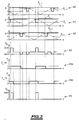
- each switch S i is associated with a periodic control signal D i .
- This switch S i / signal D i association is kept for a whole period of use of the converter 2, that is to say for a large number of operating cycles of duration T C where T C corresponds to the period of the signals D i .
- control signals D i of two successive switches S i-1 and S i are either in phase opposition, or slightly out of phase with respect to each other, but in no case in phase.
- the signals D i are here, for example, sawtooth signals varying between -1 and +1.
- the signals D i-1 , D i and D i + 1 are represented on timing diagrams 90, 91, 92 of FIG. 3 corresponding respectively to the switches S i-1 , S i and S i + 1 .
- the open or closed state of each switch S i is represented by a curve whose value is equal to 1 when the switch is closed and to 0 when the switch is open.
- the computer 50 permanently establishes, in step 82, the value of a duty cycle m as a function of the value of the setpoint received at the input 56.
- This value m is represented by a horizontal line on each of the chronograms 90 to 92.
- the computer 50 controls, at step 84, the opening and closing of all the switches of the converter 2.
- the computer 50 triggers a substep 86 for controlling the closing of the switch S i as soon as the value of the signal D i is less than the value of the duty cycle m. Conversely, as soon as the value of the signal D i is greater than that of the duty cycle m, the computer 50 triggers a substep 88 for opening the switch S i . It is this functioning which is represented on the three chronograms 90 to 92.
- Chronograms 94a and 94b of FIG. 3 represent examples of the evolution over time of the state of the switch P i respectively in the case where the current I L is greater than 0 and in the case where the current I L is less than 0.
- a value equal to 1 indicates that the switch P i is closed and a value equal to 0 indicates that the switch P i is open.
- the input voltage U SPARC is deduced from the voltages U Pi at the terminals of each of the switches of the circuit 10 using the following relation:
- the value of the duty cycle m fixes the switching instants and the conduction times of the switches S i . Since the control law of the switches P i and P ' i is deduced from that of the switches S i and S' i , this also fixes the switching times and the conduction time of the switches P i and P ' i . Thus, the average value of the voltages U Pi over an operating cycle T C , and therefore of the input voltage U SPARC , varies as a function of the value of the duty cycle m. It is therefore verified that the value of the duty cycle m fixes the overall transformation ratio of the converter 2.
- the computer 50 also controls the opening of the switch S ' i , the opening of the switch P i and the closing of the switch P' i .
- the computer 50 also controls the closing of the switch S ' i , the closing of the switch P i and the opening of the switch P' i .
- the computer 50 systematically executes, during sub-step 86, a soft switching process 96 to close the switch S i , and during sub-step 88, a soft switching process 98 to close the switch If i .
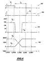
- timing diagrams 100, 102, 104 and 106 in FIG. 4 respectively represent the evolution over time of the state of the switch S ' i , of the state of the switch S i , of the currents I' Si and I Si , and voltages U Si and U ' Si , during the execution of the process 96.
- the switch S ' i is closed and a current of about 150 A passes through it, while the switch S i is open and the voltage U Si between its terminals a a value of approximately 1800 V.
- the computer begins the execution of the process 96 by controlling, during an operation 110, only the opening of the switch S ' i . Therefore, the intensity of the current Si decreases very quickly to become zero.
- the voltage U ' Si begins to increase.
- the voltage U ' Si changes over time much more slowly than the Si because the capacitor C' i slows the variations of the voltage U ' Si .
- the presence of the capacitor C ' i thus limits the switching losses during the opening of the switch S' i , since the voltage U ' Si , at the terminals of the switch S' i , is low as long as the current I ' If is not zero.
- the computer maintains, during an operation 112, simultaneously the switches S i and S ' i open for a duration T M qualified as dead time.
- This dead time ensures that the switches S i and S ' i are not simultaneously closed and thus avoids short-circuiting between them the output terminals 26 and 28.
- the capacitor C' i charges gradually and the voltage U ' Si increases slowly until reaching a value equal to that of the voltage U C.
- the freewheeling diode of the switch S i starts to drive naturally, that is to say without any command being applied to the switches S i and S ' i during the idle time. Consequently, the voltage U Si , at the terminals of the switch S i , is zero although the latter is open and the current, through the switch S i , is established only by means of the diode of freewheel.
- the value of the duration T M is chosen so that, during operation 112, the freewheeling diode of the switch S i has the time to become conductive. This time is here determined by the capacitance of the capacitor C ' i which is, for example, chosen equal to 500 nF.
- the computer 50 controls, during an operation 114, the closing of the switch S i .
- the closing of S i therefore occurs at a time when the voltage U Si is zero and the intensity I Si is also zero. The switching losses are therefore also zero.
- This degree of freedom is used in the detailed control process of Figure 5 to execute, in addition to a gentle switching process to close the switches of the secondary electrical circuit 12, a process soft switching to open the switches of the primary electrical circuit 10.
- Sub-step 86 consists in controlling the closing of the switch S i , the opening of the switch S ' i , the opening of the switch P i and the closing of the switch P' i .
- This sub-step 86 begins with an operation 124 for acquiring the intensity of the current I L using the sensor 40.
- the computer tests the value of the intensity of the current I L. If this intensity is strictly greater than 0, the computer then immediately proceeds to an operation 132 for controlling the closing of the switch S i and the opening of the switch S ' i .
- the computer 50 performs the closing of the switch S i and the opening of the switch S ' i by executing the process 96 described with reference to FIG. 2.
- the computer 50 waits, during an operation 136, for the voltage U bi to become negative in order to proceed with the operation 138 for controlling the opening of the switch P i and the closing of the switch P ' i .
- the computer 50 establishes, if the voltage U bi is strictly positive or negative, for example, only from the known control law of the switches S i , here, a control law by pulse width modulation . So no tension measurement is necessary.
- the computer 50 executes, during an operation 138 for controlling the opening of P i and the closing of P ' i , a soft switching process 140 to open the switch P i .
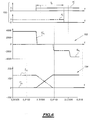
- a chronogram 152 of the evolution during the process 140, voltages U Pi and U ' Pi , as well as a chronogram 154 of the evolution during the process of the intensities I' Pi and I Pi .
- the switch P i is closed and the switch P ' i is open.
- the current I Pi is equal to approximately 130 A and the voltage U ' Pi to 3600 V.
- the current I Pi is positive because the current I L is positive.
- the process 140 then begins with an operation 160 for controlling the closing of the switch P ' i .
- the computer simultaneously controls the closing of the switching device P ' i-SUP and P' i-INF .
- the computer 50 also controls the opening of the switching device P i-INF ⁇
- This command of the opening of the switching device P i-INF does not cause any loss by switching.
- the intensity of the current I Pi is positive at the instant when the opening of the switching device P i-INF is controlled, which means that the current flows only in its freewheeling diode. Consequently, this switching is carried out at a time when no current flows through the IGBT transistor of the switching device P i-INF .
- the computer 50 maintains the switches P i and P ' i in this state for a duration T R called recovery time.
- the voltage U ' Pi drops suddenly due to the closing of the switch P' i . Then, the amplitude of the intensity of the current I Pi , flowing through the IGBT transistor of the switching device P i-SUP and the freewheeling diode of the switching device P i-INF , decreases and s' naturally cancels due to the fact that the voltage U bi is negative. Therefore, the intensity of the current I Pi remains zero although the IGBT transistor of P i-SUP is in the on state, since it cannot change direction due to the fact that the IGBT transistor of the switching device P i-INF is open.
- the duration of the recovery time T R is chosen to be greater than the time necessary for the intensity of the current I Pi to cancel out. During this recovery time, no command is applied to the switches P i , P ' i .
- the switches P i and P ' i are simultaneously conductive, which guarantees switching of the switches P i and P' i without interrupting the flow of current I L.
- the computer When the duration T R has elapsed, the computer immediately proceeds to the operation 164 for controlling the opening of the switching device P i-SUP .
- the switching device P i-SUP is opened at zero current I Pi , so that the switching losses are also zero.
- the process 140 for soft switching control of the opening of the switch P i then ends and the computer proceeds to sub-step 88.
- the computer 50 then proceeds to an operation 168 of opening the switch P i and of closing the switch P ' i before perform an operation 170 for controlling the closing of the switch S i and the opening of the switch S ' i .
- the computer also executes a soft switching process 172 to open the switch P i .
- This process 172 is executed under conditions where the intensity of the current I L is negative and where the voltage U bi is positive, since the computer has not yet carried out the operation 170 of closing the switch S i and opening of the switch S ' i . Consequently, this process 172 is identical to the process 140 of operation 138 by replacing the terms "P i-INF " and "P i-SUP " respectively by "P i-SUP " and "P i-INF ".
- Operation 170 is, for example, identical to operation 132.
- the computer proceeds to the substep 88.
- the vertical dotted line representing the instant of closing of the switch S i is offset with respect to the theoretical instant of closing of the switch S i determined solely using the law of control by pulse width modulation (shown in timing diagram 91).
- This offset represents the delay introduced to first command the opening of the switch P i before the closing of the switch S i .
- this shift is very clearly amplified by way of illustration. In reality, this offset is small compared to the opening time of the switches S i .
- sub-step 88 the computer 50 controls the opening of the switch S i , the closing of the switch S ' i , the closing of the switch P i and the opening of the switch P' i .
- the computer executes soft switching processes to close the switch S ' i and to open the switch P' i .
- the soft switching processes are identical to those described for sub-step 86 with the exception that the commands applied to the switches S i and P i are replaced by corresponding commands applied to the switches S ' i and P' i . Consequently, the operations carried out during sub-step 88 are identical to those carried out during sub-step 86. The details of these operations will therefore not be described here.
- the duration of the dead time T M and the duration of the recovery time T R are chosen as small as possible, so that the switches P i and P ' i , respectively S i and S ' i , are in complementary states for 98% of the time of use of the converter 2.
- the soft switching process to open the switch P i is advanced or delayed in time to be placed at an instant when the value of the voltage U bi naturally cancels the intensity in the switch P i .
- the opening of P i is delayed relative to the closing of S i if the current I L is positive, and the closing of S i is delayed to be performed after the opening of P i if the current I L is negative.
- the computer commands at this instant the closing of the switch S i , while if the intensity of the current I L is negative, the computer commands the opening of the switch P i at this instant.
- the computer slightly delays the closing of the switch S i with respect to the theoretical instant determined from the control law by pulse width modulation. It is therefore understood that the control by pulse width modulation fixes theoretical switching moments suitable for obtaining a given transformation ratio.
- the computer slightly shifts the real switching instants of the switches P i , P ' i, S i and S' i, compared to these theoretical instants to either maintain the operating conditions of the converter capable of allowing the execution of a soft switching process (for example maintaining the voltage U Pi greater than 0 by first executing the opening of the switch P i during the operation 168 then the closing of the switch S i during the operation 170) or wait until the operating conditions of the converter allow the execution of such a process (here, for example, wait until the voltage U bi is negative in step 136).
- a soft switching process for example maintaining the voltage U Pi greater than 0 by first executing the opening of the switch P i during the operation 168 then the closing of the switch S i during the operation 170
- wait until the operating conditions of the converter allow the execution of such a process here, for example, wait until the voltage U bi is negative in step 136.
Landscapes
- Engineering & Computer Science (AREA)
- Power Engineering (AREA)
- Dc-Dc Converters (AREA)
Abstract
Description
- ladite au moins une étape d'exécution d'un processus de commutation douce est uniquement réalisée à un instant où les conditions de fonctionnement dudit ensemble sont propres à permettre une annulation naturelle du paramètre de fonctionnement de l'interrupteur à commuter ;
- le processus de commutation douce comporte une opération consistant à commander au moins un autre interrupteur que celui à commuter de manière à déclencher un processus d'annulation naturelle du paramètre de fonctionnement de l'interrupteur à commuter ;
- au moins l'un des circuits électriques comportant un étage
élémentaire formé par un circuit électrique fermé dans lequel sont placés, dans
l'ordre, un premier enroulement, un premier interrupteur commandable, un
second enroulement, et un second interrupteur commandable, le procédé
comporte une étape d'exécution d'un processus de commutation douce pour
ouvrir un interrupteur dudit étage élémentaire, ce processus comportant des
opérations consistant à :
- commander la fermeture de l'autre interrupteur du même étage élémentaire, puis
- attendre que l'intensité du courant s'annule naturellement dans l'interrupteur à ouvrir, puis
- commander l'ouverture de l'interrupteur à ouvrir lorsque l'intensité du courant le traversant est nulle ;
- l'interrupteur à ouvrir étant formé de deux dispositifs de commutation formés chacun d'un élément de commutation commandable et d'un élément formant diode de roue libre raccordé en position antiparallèle aux bornes de l'élément de commutation commandable, ces dispositifs de commutation étant raccordés en série et tête-bêche et les éléments de commutation étant adaptés pour que, quel que soit le sens du courant traversant l'interrupteur à ouvrir, au plus un des deux éléments de commutation soit conducteur à un instant donné, le processus de commutation douce pour ouvrir l'interrupteur comporte également une opération, avant d'attendre que l'intensité du courant s'annule naturellement, consistant à commander, en fonction du sens du courant circulant dans l'interrupteur l'ouverture de l'élément de commutation de l'interrupteur à ouvrir qui n'est pas traversé par le courant ;
- l'étape d'exécution du processus de commutation douce pour ouvrir un interrupteur est réalisée uniquement lorsque la tension aux bornes de l'interrupteur à ouvrir est propre à annuler naturellement l'intensité du courant le traversant ;
- la présence de la tension propre à annuler naturellement l'intensité du courant traversant l'interrupteur à ouvrir dans l'un des circuits électriques est déterminée à partir de la loi de commande des interrupteurs commandables de l'autre circuit électrique ;
- il comporte un processus de commutation douce pour fermer un
interrupteur, ce processus comportant les étapes consistant à :
- commander au moins un autre interrupteur du même circuit électrique de manière à déclencher un processus d'annulation naturelle de la tension dans l'interrupteur à fermer, puis
- commander la fermeture de l'interrupteur à fermer lorsque la tension aux bornes de l'interrupteur à fermer est nulle ;
- l'interrupteur à fermer étant formé d'un dispositif de commutation comportant un élément de commutation commandable adapté pour ne conduire le courant que dans un sens et un élément formant diode de roue libre raccordé en position antiparallèle aux bornes de l'élément de commutation, l'étape de commande dudit au moins un autre interrupteur du même circuit consiste à commander ledit au moins un autre interrupteur de manière à rendre conducteur ledit élément formant diode de roue libre avant de commander la fermeture de l'interrupteur ;
- l'étape d'exécution du processus de commutation douce pour fermer un interrupteur est uniquement réalisée à des instants fixés par une loi de commande en fonction d'un rapport de transformation global souhaité pour ledit ensemble ;
- chaque circuit électrique comportant une succession de cellules de commutation, chaque cellule présentant une structure de pont en H dans lequel un enroulement de transformateur est placé dans la branche intermédiaire du pont en H et quatre interrupteurs de commande du sens du courant dans cet enroulement sont respectivement placés dans chacune des branches supérieures et inférieures du pont en H, le procédé comporte l'étape de commander les interrupteurs des branches supérieures/inférieures du pont en H de chaque cellule de façon complémentaire pendant au moins 85 % du temps, le pourcentage du temps restant étant utilisé pour ménager soit un temps de recouvrement pendant lequel les interrupteurs des branches supérieures/inférieures du même pont en H sont simultanément conducteurs, soit un temps mort pendant lequel les interrupteurs des branches supérieures/inférieures du même pont en H sont simultanément non conducteurs.
- la figure 1 est une illustration schématique d'un ensemble de transformateurs associé à un système de commande conforme à l'invention ;
- la figure 2 est un organigramme d'un premier procédé de commande conforme à l'invention de l'ensemble de transformateurs de la figure 1 ;
- la figure 3 est un chronogramme des signaux de commande mis en oeuvre dans le procédé de la figure 2 ;
- la figure 4 est un chronogramme de deux paramètres de fonctionnement d'un interrupteur commandé à l'aide du procédé de la figure 2 ;
- la figure 5 est un organigramme d'un second procédé de commande de l'ensemble de la figure 1 conforme à l'invention ; et
- la figure 6 est un chronogramme de deux paramètres de fonctionnement d'un interrupteur commandé à l'aide du procédé de la figure 5.
- IPi et I'Pi désignent les courants traversant respectivement les interrupteurs Pi et P'i orientés de la borne 16 vers la borne 18,
- UPi et U'Pi les tensions aux bornes respectivement des interrupteurs Pi et P'i,
- ISi et l'Si les courants traversant respectivement les interrupteurs Si et S'i orientés de la borne de sortie 28 vers la borne de sortie 26, et
- USi et U'Si les tensions respectivement aux bornes des interrupteurs Si et Si'.
- k est le rapport de transformation constant de chacun des transformateurs Ti, et
- Si-1, Si et Si+1 sont des variables booléennes représentant respectivement l'état des interrupteurs Si-1, Si et Si+1, ces variables ont une valeur égale à 0 lorsque l'interrupteur est ouvert et à 1 lorsque l'interrupteur est fermé.
- UPi représente la tension aux bornes de l'interrupteur Pi, et
- Pi est une variable booléenne égale à 0 lorsque l'interrupteur Pi et ouvert et à 1 lorsque Pi est fermé.

Claims (15)
- Procédé de commande d'un ensemble (2) de transformateurs (Ti) indépendants magnétiquement les uns des autres, ledit ensemble (2) comportant un premier et un second circuits électriques (10, 12) raccordant entre eux respectivement les enroulements primaires et secondaires des transformateurs (Ti) par l'intermédiaire d'interrupteurs commandables (Pi, P'i, Si, S';) propres à raccorder ces enroulements soit en parallèle, soit en série,
caractérisé en ce qu'il comporte au moins une étape (132, 138, 168, 170) d'exécution d'un processus (96, 98, 140, 172) de commutation douce pour commander la commutation d'un desdits interrupteurs commandables, ledit processus comportant une opération de commande de la commutation de l'interrupteur, à un instant où un paramètre de fonctionnement de l'interrupteur s'est naturellement annulé, ce paramètre de fonctionnement étant choisi parmi l'intensité du courant traversant l'interrupteur à commuter et la tension aux bornes de l'interrupteur à commuter. - Procédé selon la revendication 1, caractérisé en ce que ladite au moins une étape (132, 138, 168, 170) d'exécution d'un processus de commutation douce est uniquement réalisée à un instant où les conditions de fonctionnement dudit ensemble (2) sont propres à permettre une annulation naturelle du paramètre de fonctionnement de l'interrupteur à commuter.
- Procédé selon la revendication 2, caractérisé en ce que le processus (96, 140) de commutation douce comporte une opération (110, 160) consistant à commander au moins un autre interrupteur que celui à commuter de manière à déclencher un processus d'annulation naturelle du paramètre de fonctionnement de l'interrupteur à commuter.
- Procédé selon l'une quelconque des revendications précédentes, caractérisé en ce qu'au moins l'un des circuits électriques (10) comportant un étage élémentaire formé par un circuit électrique fermé dans lequel sont placés, dans l'ordre, un premier enroulement, un premier interrupteur commandable, un second enroulement, et un second interrupteur commandable, le procédé comporte une étape (138, 168) d'exécution d'un processus (140, 172) de commutation douce pour ouvrir un interrupteur (Pi, P'i) dudit étage élémentaire, ce processus comportant des opérations consistant à :commander (en 160) la fermeture de l'autre interrupteur du même étage élémentaire, puisattendre (en 162) que l'intensité du courant s'annule naturellement dans l'interrupteur à ouvrir, puiscommander (en 164) l'ouverture de l'interrupteur à ouvrir lorsque l'intensité du courant le traversant est nulle.
- Procédé selon la revendication 4, caractérisé en ce que l'interrupteur à ouvrir étant formé de deux dispositifs de commutation (Pi-SUP, Pi-INF) formés chacun d'un élément de commutation commandable et d'un élément formant diode de roue libre raccordé en position antiparallèle aux bornes de l'élément de commutation commandable, ces dispositifs de commutation (Pi-SUP, Pi-INF) étant raccordés en série et tête-bêche et les éléments de commutation étant adaptés pour que, quel que soit le sens du courant traversant l'interrupteur à ouvrir, au plus un des deux éléments de commutation soit conducteur à un instant donné, le processus de commutation douce (140, 172) pour ouvrir l'interrupteur comporte également une opération (160), avant d'attendre que l'intensité du courant s'annule naturellement, consistant à commander, en fonction du sens du courant circulant dans l'interrupteur (Pi), l'ouverture de l'élément de commutation de l'interrupteur à ouvrir qui n'est pas traversé par le courant.
- Procédé selon la revendication 4 ou 5, caractérisé en ce que l'étape (138, 168) d'exécution du processus (140, 170) de commutation douce pour ouvrir un interrupteur est réalisée uniquement lorsque la tension aux bornes de l'interrupteur à ouvrir est propre à annuler naturellement l'intensité du courant le traversant.
- Procédé selon la revendication 6, caractérisé en ce que la présence de la tension propre à annuler naturellement l'intensité du courant traversant l'interrupteur à ouvrir dans l'un des circuits électriques (10) est déterminée (en 162) à partir de la loi de commande des interrupteurs commandables de l'autre circuit électrique (12).
- Procédé selon l'une quelconque des revendications précédentes, caractérisé en ce qu'il comporte un processus (96, 98) de commutation douce pour fermer un interrupteur, ce processus comportant les étapes consistant à :commander (en 110) au moins un autre interrupteur du même circuit électrique (10, 12) de manière à déclencher un processus d'annulation naturelle de la tension dans l'interrupteur à fermer, puiscommander (en 114) la fermeture de l'interrupteur à fermer lorsque la tension aux bornes de l'interrupteur à fermer est nulle.
- Procédé selon la revendication 8, caractérisé en ce que l'interrupteur à fermer étant formé d'un dispositif de commutation comportant un élément de commutation commandable adapté pour ne conduire le courant que dans un sens et un élément formant diode de roue libre raccordé en position antiparallèle aux bornes de l'élément de commutation, l'étape de commande dudit au moins un autre interrupteur du même circuit (10, 12) consiste à commander ledit au moins un autre interrupteur de manière à rendre conducteur ledit élément formant diode de roue libre avant de commander la fermeture de l'interrupteur.
- Procédé selon la revendication 8 ou 9, caractérisé en ce que l'étape d'exécution du processus (96) de commutation douce pour fermer un interrupteur est uniquement réalisée à des instants fixés par une loi de commande en fonction d'un rapport de transformation global souhaité pour ledit ensemble (2).
- Procédé selon l'une quelconque des revendications précédentes, caractérisé en ce que chaque circuit électrique (10, 12) comportant une succession de cellules de commutation, chaque cellule présentant une structure de pont en H dans lequel un enroulement de transformateur est placé dans la branche intermédiaire du pont en H et quatre interrupteurs de commande du sens du courant dans cet enroulement sont respectivement placés dans chacune des branches supérieures et inférieures du pont en H, le procédé comporte l'étape (84) de commander les interrupteurs des branches supérieures/inférieures du pont en H de chaque cellule de façon complémentaire pendant au moins 85 % du temps, le pourcentage du temps restant étant utilisé pour ménager soit un temps de recouvrement pendant lequel les interrupteurs des branches supérieures/inférieures du même pont en H sont simultanément conducteurs, soit un temps mort pendant lequel les interrupteurs des branches supérieures/inférieures du même pont en H sont simultanément non conducteurs.
- Système de commande d'un ensemble (2) de transformateurs (Ti) indépendants magnétiquement les uns des autres, ledit ensemble (2) comportant un premier et un second circuits électriques (10, 12) raccordant entre eux respectivement les enroulements primaires et secondaires des transformateurs (Ti) par l'intermédiaire d'interrupteurs commandables (Pi, P'i, Si, S'i) propres à raccorder ces enroulements soit en parallèle, soit en série,
caractérisé en ce qu'il comporte un calculateur (50) apte à réaliser au moins une étape (132, 138, 168, 170) d'exécution d'un processus (96, 98, 140, 172) de commutation douce pour commander la commutation d'un desdits interrupteurs commandables, ledit processus comportant une opération de commande de là commutation de l'interrupteur, à un instant où un paramètre de fonctionnement de l'interrupteur s'est naturellement annulé, ce paramètre de fonctionnement étant choisi parmi l'intensité du courant traversant l'interrupteur à commuter et la tension aux bornes de l'interrupteur à commuter. - Support (52) d'enregistrement d'informations comportant des instructions pour l'exécution d'un procédé de commande d'un ensemble (2) de transformateurs indépendants magnétiquement les uns des autres, conforme à l'une quelconque des revendications 1 à 11, lorsque lesdites instructions sont exécutées par un calculateur électronique (50).
- Système de conversion d'énergie électrique, comportant :caractérisé :un ensemble (2) de transformateurs (Ti) indépendants magnétiquement les uns des autres, ledit ensemble comportant :un premier et un second circuits électriques (10, 12) raccordant entre eux respectivement les enroulements primaire et secondaire des transformateurs (Ti), etdes interrupteurs commandables (Pi, P'i, Si et S'i) propres à raccorder ces enroulements soit en parallèle, soit en série, etun système de commande de cet ensemble (2),en ce que le système de commande est conforme à la revendication 12, eten ce que l'ensemble (2) comporte des condensateurs raccordés en parallèle aux bornes des interrupteurs d'au moins un desdits circuits électriques (10, 12) pour limiter les pertes par commutation.
- Système selon la revendication 14, caractérisé en ce que chaque circuit électrique (10, 12) comporte une succession de cellules de commutation, chaque cellule présentant une structure de pont en H dans lequel un enroulement de transformateur est placé dans la branche intermédiaire du pont en H et quatre interrupteurs commandables pour déterminer le sens du courant dans cet enroulement sont respectivement placés dans chacune des branches supérieure et inférieure du pont en H.
Applications Claiming Priority (2)
| Application Number | Priority Date | Filing Date | Title |
|---|---|---|---|
| FR0214748 | 2002-11-25 | ||
| FR0214748A FR2847740B1 (fr) | 2002-11-25 | 2002-11-25 | Procede et systeme de commande d'un ensemble de transformateurs independants magnetiquement les uns des autres, et support d'enregistrement d'informations comportant des instructions pour l'execution du procede |
Publications (1)
| Publication Number | Publication Date |
|---|---|
| EP1422816A1 true EP1422816A1 (fr) | 2004-05-26 |
Family
ID=32187810
Family Applications (1)
| Application Number | Title | Priority Date | Filing Date |
|---|---|---|---|
| EP03356186A Withdrawn EP1422816A1 (fr) | 2002-11-25 | 2003-11-24 | Procédé et système de commande d'un ensemble de transformateurs indépendants magnétiquement les uns des autres, et support d'enregistrement d'informations comportant des instructions pour l'exécution du procédé |
Country Status (2)
| Country | Link |
|---|---|
| EP (1) | EP1422816A1 (fr) |
| FR (1) | FR2847740B1 (fr) |
Citations (2)
| Publication number | Priority date | Publication date | Assignee | Title |
|---|---|---|---|---|
| US20020024824A1 (en) * | 2000-08-09 | 2002-02-28 | Harry Reinold | High-voltage DC/DC converter |
| FR2820561A1 (fr) * | 2001-02-05 | 2002-08-09 | Faiveley Transport | Circuit electronique de connexion en serie et/ou en parallele de generateurs |
-
2002
- 2002-11-25 FR FR0214748A patent/FR2847740B1/fr not_active Expired - Fee Related
-
2003
- 2003-11-24 EP EP03356186A patent/EP1422816A1/fr not_active Withdrawn
Patent Citations (2)
| Publication number | Priority date | Publication date | Assignee | Title |
|---|---|---|---|---|
| US20020024824A1 (en) * | 2000-08-09 | 2002-02-28 | Harry Reinold | High-voltage DC/DC converter |
| FR2820561A1 (fr) * | 2001-02-05 | 2002-08-09 | Faiveley Transport | Circuit electronique de connexion en serie et/ou en parallele de generateurs |
Non-Patent Citations (2)
| Title |
|---|
| OLIVEIRA D S ET AL: "A lossless commutation PWM two level forward converter", IEEE, 10 September 2000 (2000-09-10), pages 582 - 588, XP010523244 * |
| PINHEIRO J R ET AL: "Isolated interleaved-phase-shift-PWM de-dc ZVs converters", IEEE, vol. 4, 8 October 2000 (2000-10-08), pages 2383 - 2388, XP010522589 * |
Also Published As
| Publication number | Publication date |
|---|---|
| FR2847740B1 (fr) | 2006-12-15 |
| FR2847740A1 (fr) | 2004-05-28 |
Similar Documents
| Publication | Publication Date | Title |
|---|---|---|
| CA2183789C (fr) | Dispositif electronique de conversion de l'energie electrique | |
| EP2104213B1 (fr) | Procédé d'asservissement d'un convertisseur DC-DC en mode discontinu | |
| FR2752111A1 (fr) | Procede et dispositif de commande d'onduleurs | |
| EP1320920A1 (fr) | Dispositif de conversion d'energie electrique a decoupage | |
| EP2208276A1 (fr) | Procédé de fonctionnement et dispositif de commande d'une installation énergétique à modules photovoltaïques | |
| FR2922374A1 (fr) | Dispositif de suppression de courant entrant | |
| FR2487142A1 (fr) | Circuit et procede de conversion a/n ou n/a de signaux bipolaires utilisant une unique tension de reference | |
| FR2562284A1 (fr) | Regulateur predictif de retour a modulation d'impulsions en duree | |
| FR2485827A1 (fr) | Procede et systeme pour la production de puissance photovoltaique | |
| FR2933547A1 (fr) | Ondulateur trois niveaux | |
| FR2556899A1 (fr) | Procede et appareil pour commander la moyenne des demi-alternances ou la moyenne quadratique de la tension d'une charge | |
| EP0798847A1 (fr) | Convertisseur de fréquence pour moteur alternatif | |
| EP3910774A1 (fr) | Commande de convertisseur à découpage | |
| EP3910775A1 (fr) | Commande de convertisseur à découpage | |
| FR2460564A1 (fr) | Ensemble de filtrage par commutation | |
| FR2565433A1 (fr) | Convertisseur de puissance a controle par cycles | |
| EP0278193A1 (fr) | Circuit de mesure de la composante continue du courant parcourant l'enroulement primaire du transformateur de sortie d'un onduleur | |
| BE1001902A3 (fr) | Convertisseur de source de courant a precommutation. | |
| FR2847740A1 (fr) | Procede et systeme de commande d'un ensemble de transformateurs independants magnetiquement les uns des autres, et support d'enregistrement d'informations comportant des instructions pour l'execution du procede | |
| FR2646297A1 (fr) | Procede de commande d'interrupteurs pour l'alimentation en ondes entieres d'un circuit triphase | |
| EP0267252B1 (fr) | Convertisseur de frequence pour l'alimentation stabilisee de moteurs asynchrones | |
| EP1420262B1 (fr) | Procédé et système de détection d'au moins une défaillance d'au moins un interrupteur dans un convertisseur électronique | |
| FR2961977A1 (fr) | Procede de commande et systeme pour compenser les temps-morts dans une commande mli | |
| EP1410488B1 (fr) | Dispositif de conversion d'energie | |
| EP3910776A1 (fr) | Commande de convertisseur à découpage |
Legal Events
| Date | Code | Title | Description |
|---|---|---|---|
| PUAI | Public reference made under article 153(3) epc to a published international application that has entered the european phase |
Free format text: ORIGINAL CODE: 0009012 |
|
| AK | Designated contracting states |
Kind code of ref document: A1 Designated state(s): AT BE BG CH CY CZ DE DK EE ES FI FR GB GR HU IE IT LI LU MC NL PT RO SE SI SK TR |
|
| AX | Request for extension of the european patent |
Extension state: AL LT LV MK |
|
| 17P | Request for examination filed |
Effective date: 20040909 |
|
| RAP1 | Party data changed (applicant data changed or rights of an application transferred) |
Owner name: ALSTOM |
|
| AKX | Designation fees paid |
Designated state(s): AT BE BG CH CY CZ DE DK EE ES FI FR GB GR HU IE IT LI LU MC NL PT RO SE SI SK TR |
|
| 17Q | First examination report despatched |
Effective date: 20110316 |
|
| STAA | Information on the status of an ep patent application or granted ep patent |
Free format text: STATUS: THE APPLICATION IS DEEMED TO BE WITHDRAWN |
|
| 18D | Application deemed to be withdrawn |
Effective date: 20110926 |