EP1422785A2 - Antenna and method for manufacturing the same - Google Patents
Antenna and method for manufacturing the same Download PDFInfo
- Publication number
- EP1422785A2 EP1422785A2 EP03026932A EP03026932A EP1422785A2 EP 1422785 A2 EP1422785 A2 EP 1422785A2 EP 03026932 A EP03026932 A EP 03026932A EP 03026932 A EP03026932 A EP 03026932A EP 1422785 A2 EP1422785 A2 EP 1422785A2
- Authority
- EP
- European Patent Office
- Prior art keywords
- resin member
- resin
- mold
- protrusions
- tip end
- Prior art date
- Legal status (The legal status is an assumption and is not a legal conclusion. Google has not performed a legal analysis and makes no representation as to the accuracy of the status listed.)
- Withdrawn
Links
Images




Classifications
-
- B—PERFORMING OPERATIONS; TRANSPORTING
- B29—WORKING OF PLASTICS; WORKING OF SUBSTANCES IN A PLASTIC STATE IN GENERAL
- B29C—SHAPING OR JOINING OF PLASTICS; SHAPING OF MATERIAL IN A PLASTIC STATE, NOT OTHERWISE PROVIDED FOR; AFTER-TREATMENT OF THE SHAPED PRODUCTS, e.g. REPAIRING
- B29C45/00—Injection moulding, i.e. forcing the required volume of moulding material through a nozzle into a closed mould; Apparatus therefor
- B29C45/16—Making multilayered or multicoloured articles
-
- H—ELECTRICITY
- H01—ELECTRIC ELEMENTS
- H01Q—ANTENNAS, i.e. RADIO AERIALS
- H01Q1/00—Details of, or arrangements associated with, antennas
- H01Q1/36—Structural form of radiating elements, e.g. cone, spiral, umbrella; Particular materials used therewith
- H01Q1/362—Structural form of radiating elements, e.g. cone, spiral, umbrella; Particular materials used therewith for broadside radiating helical antennas
-
- H—ELECTRICITY
- H01—ELECTRIC ELEMENTS
- H01Q—ANTENNAS, i.e. RADIO AERIALS
- H01Q1/00—Details of, or arrangements associated with, antennas
- H01Q1/40—Radiating elements coated with or embedded in protective material
-
- B—PERFORMING OPERATIONS; TRANSPORTING
- B29—WORKING OF PLASTICS; WORKING OF SUBSTANCES IN A PLASTIC STATE IN GENERAL
- B29C—SHAPING OR JOINING OF PLASTICS; SHAPING OF MATERIAL IN A PLASTIC STATE, NOT OTHERWISE PROVIDED FOR; AFTER-TREATMENT OF THE SHAPED PRODUCTS, e.g. REPAIRING
- B29C45/00—Injection moulding, i.e. forcing the required volume of moulding material through a nozzle into a closed mould; Apparatus therefor
- B29C45/16—Making multilayered or multicoloured articles
- B29C2045/1681—Making multilayered or multicoloured articles one layer penetrating at one or more areas through another layer
-
- B—PERFORMING OPERATIONS; TRANSPORTING
- B29—WORKING OF PLASTICS; WORKING OF SUBSTANCES IN A PLASTIC STATE IN GENERAL
- B29C—SHAPING OR JOINING OF PLASTICS; SHAPING OF MATERIAL IN A PLASTIC STATE, NOT OTHERWISE PROVIDED FOR; AFTER-TREATMENT OF THE SHAPED PRODUCTS, e.g. REPAIRING
- B29C45/00—Injection moulding, i.e. forcing the required volume of moulding material through a nozzle into a closed mould; Apparatus therefor
- B29C45/14—Injection moulding, i.e. forcing the required volume of moulding material through a nozzle into a closed mould; Apparatus therefor incorporating preformed parts or layers, e.g. injection moulding around inserts or for coating articles
- B29C45/14065—Positioning or centering articles in the mould
-
- B—PERFORMING OPERATIONS; TRANSPORTING
- B29—WORKING OF PLASTICS; WORKING OF SUBSTANCES IN A PLASTIC STATE IN GENERAL
- B29L—INDEXING SCHEME ASSOCIATED WITH SUBCLASS B29C, RELATING TO PARTICULAR ARTICLES
- B29L2031/00—Other particular articles
- B29L2031/34—Electrical apparatus, e.g. sparking plugs or parts thereof
- B29L2031/3456—Antennas, e.g. radomes
Definitions
- the present invention relates to an antenna using an antenna element formed from a helical coil or the like, and a method for manufacturing such an antenna.
- Antennas using antenna elements formed from helical coils etc. are generally used as ones for automobile use or for cellular phone use.
- a change in pitch of a helical coil or the like results in a change in its antenna characteristic.
- the shape of the helical coil has to be fixed to prevent its pitch or the like from being changed.
- Japanese Patent Publication No. 2000-252733A discloses an antenna element formed of a helical coil is first inserted into a mold, and the outer circumference of the antenna element is brought into contact with the inner surface of the mold so as to be placed at a predetermined position therein. Then, insulating resin is injected into the mold so as to mold a resin molded member integrally with the antenna element.
- a plurality of recess portions having a predetermined depth are formed in the inner surface of the mold in advance so that protrusions having a predetermined height are formed on the outer circumferential surface of the resin molded member integrally therewith.
- the pitch of the antenna element is fixed by the resin molded member, and the shape of the antenna element is prevented from being deformed. Thus, the antenna characteristic is stabilized.
- the outer circumference of the antenna element is exposed from the outer circumferential surface of the resin molded member.
- the resin molded member is inserted into another mold, and the tips of the predetermined-height protrusions provided in the outer circumferential surface of the resin molded member are brought into contact with the inner surface of the mold so as to be placed at a predetermined position therein. Then, insulating resin is injected into the mold so that a resin coating having a thickness equal to the height of the protrusions is molded integrally with the resin molded member so as to cover the resin molded member with the resin coating.
- the antenna element is covered with the resin coating so that the outside of the antenna element is electrically insulated, while the antenna element is prevented from being exposed to the atmosphere in order not to be rusted.
- the resin is injected into the mold for forming the resin coating, at a center part of the antenna in a longitudinal (axial) direction thereof.
- the injecting direction is substantially perpendicular to the axial direction of the antenna.
- the lateral injection force strongly acts on the resin molded member so that the resin molded member is apt to be out of its proper position in the mold because the protrusions provided in the outer circumferential surface of the resin molded member cannot bear the injection force.
- the resin molded member is not coated with the resin coating by a predetermined thickness.
- the injection pressure of the resin is too low, the resin cannot reach every part of the mold satisfactorily.
- a sink is apt to be formed in the resin coating so that a large thickness variation is occurred in the resin coating.
- an antenna comprising:
- the tip end portion of the first resin member is shaped into a prismoid having conical faces facing directions at which the protrusions are arranged.
- the tip end portion of the first resin member may be shaped into a pyramid having conical faces facing directions at which the protrusions are arranged.
- the first mold is configured such that the tip end portion of the first resin member is shaped into a prismoid having conical faces facing directions at which the protrusions are arranged.
- the first mold may be configured such that the tip end portion of the first resin member is shaped into a pyramid having conical faces facing directions at which the protrusions are arranged.
- the insulating resin injected into the second mold is equally divided to flow into the second mold by the tip end portion of the first resin member, so that the injected resin uniformly flows over the outer periphery of the first resin member. Accordingly, there is no probability that the first resin member is displaced in the second mold. As a result, the second resin member can be coated on the first resin member with a uniform thickness.
- an antenna element 10 comprises: an attachment screw 10a at the base end; a spring portion 10b of solid coiling provided on the attachment screw 10a; a connection fitting 10c; and a helical coil element 10d provided at the tip of the spring portion 10b through the connection fitting 10c.
- the attachment screw 10a, the spring portion 10b, the connection fitting 10c and the helical coil element 10d are electrically connected to operate as an antenna as a whole.
- the portion of the antenna element 10 corresponding to the connection fitting 10c and the helical coil element 10d is inserted into a not-shown mold for molding a resin molded member.
- the outer circumference of the helical coil element 10d is brought into contact with the inner surface of the mold so as to be placed at a predetermined position therein.
- Insulating resin is injected into the mold so that a resin molded member 12 is molded integrally with the antenna element 10, as shown in Fig. 2.
- a plurality of protrusions 12a having a predetermined height are arranged on the outer circumferential face of the resin molded member 12 at a fixed interval in a circumferential direction thereof.
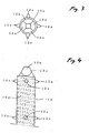
- four protrusions 12a are provided to form one set of the protrusions as shown in Fig. 3.
- a plurality sets of the protrusions are arranged in the axial direction of the antenna element 10.
- the tip end portion of the resin molded member 12 is formed into a quadrangular prismoid 12c whose conical faces 12b face the directions at which the protrusions 12a are arranged.
- the quadrangular prismoid 12c is molded integrally by a quadrangular prismoid concave provided in a tip end portion of the mold for molding the resin molded member, in the same manner as the protrusions 12a are molded.
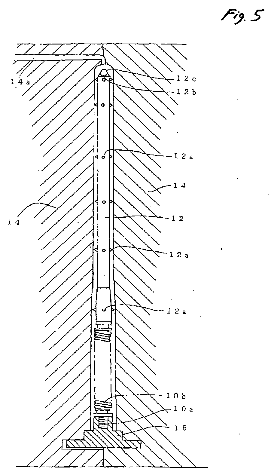
- the whole of the thus configured resin molded member 12 is inserted between molds 14 for forming a resin coating as shown in Fig. 5.
- the attachment screw 10a is screwed down to a fixed insert 16, and the fixed insert 16 is fixed suitably to the molds 14.
- the tips of the protrusions 12a of the resin molded member 12 are brought into contact with the inner surfaces of the molds 14 so as to be placed at a predetermined position therein.
- a liner 14a is opened on the tip end side of the antenna so that insulating resin is injected into the molds 14 from the tip end side of the antenna.
- the injected resin is equally divided into four by the ridges of the quadrangular prismoid 12c, and further guided toward the base end of the antenna along the conical faces 12b.
- the injected resin flows substantially uniformly over the outer circumference of the tip end portion of the resin molded member 12, and flows substantially uniformly all over the outer circumference of the resin molded member 12 including the spring portion 10b and the connection fitting 10c.
- a resin coating 16 is molded integrally so as to have a thickness equal to the predetermined height of the protrusions 12a as shown in Fig. 6.
- the shape of the tip end portion of the resin molded member 12 may not be the quadrangular prismoid 12c so long as the injected insulating resin can be equally divided and can be uniformly flowed over the outer circumference of the resin molded member 12.
- ribs may be formed with fixed intervals in the circumferential direction of the tip end portion.
- the cross sectional shape of the tip end portion may be changed so long as ridge portions are arranged with fixed intervals in the circumferential direction of the tip end portion. For example, in order to make the injected resin flow smooth, each portion between the ridges may be curved inward.
- the tip end portion of the resin molded member 12 may be formed into a quadrangular pyramid, a triangular pyramid or a pentagonal pyramid.
- the conical faces 12b of the prismoid or pyramid may not face the directions at which the protrusions 12a are arranged.
- the conical faces 12b may face the directions where are between the protrusions 12a in the circumferential direction of the resin molded member 12, so long as the injected insulating resin can be equally divided and can be uniformly flowed over the outer circumference of the resin molded member 12.
- the embodiment is designed for an automobile antenna capable of being elastically deformed at the spring portion 10b when lateral external force acts on the antenna. If it is not necessary for the antenna to be elastically deformed in accordance with external force acting thereon, the helical coil element 10d may be provided directly on the attachment screw 10a.
- the insulating resin for molding the resin molded member 12 and the resin coating 16 has to be a material having proper elasticity to allow the antenna to be elastically deformed.
Landscapes
- Engineering & Computer Science (AREA)
- Manufacturing & Machinery (AREA)
- Mechanical Engineering (AREA)
- Details Of Aerials (AREA)
- Injection Moulding Of Plastics Or The Like (AREA)
- Moulds For Moulding Plastics Or The Like (AREA)
Abstract
Description
Claims (6)
- An antenna, comprising:an antenna element;a first resin member, integrally molded with the antenna element, the first resin member including:a plurality of protrusions, formed on an outer peripheral face of the first resin member and arranged with a fixed interval relative to a circumferential direction of the first resin member; anda tip end portion, having a cross sectional shape in which projected portions are arranged with a fixed interval relative to the circumferential direction of the first resin member; anda second resin member, coated on the first resin member so as to have a thickness substantially identical with a height of each of the protrusions.
- The antenna as set forth in claim 1, wherein the tip end portion of the first resin member is shaped into a prismoid having conical faces facing directions at which the protrusions are arranged.
- The antenna as set forth in claim 1, wherein the tip end portion of the first resin member is shaped into a pyramid having conical faces facing directions at which the protrusions are arranged.
- A method of manufacturing an antenna, comprising steps of:providing an antenna element;placing the antenna element in a first mold for molding a first resin member including:a plurality of protrusions, formed on an outer peripheral face of the first resin member and arranged with a fixed interval relative to a circumferential direction of the first resin member; anda tip end portion, having a cross sectional shape in which projected portions are arranged with a fixed interval relative to the circumferential direction of the first resin member;injecting insulating resin into the first mold to form the first resin member;placing the first resin member in a second mold such that the protrusions are brought into contact with an inner face of the second mold; andinjecting insulating resin into the second mold from a gate confronting the tip end portion of the first resin member, to form a second resin member coated on the first resin member.
- The manufacturing method as set forth in claim 4, wherein the first mold is configured such that the tip end portion of the first resin member is shaped into a prismoid having conical faces facing directions at which the protrusions are arranged.
- The manufacturing method as set forth in claim 4, wherein the first mold is configured such that the tip end portion of the first resin member is shaped into a pyramid having conical faces facing directions at which the protrusions are arranged.
Applications Claiming Priority (2)
| Application Number | Priority Date | Filing Date | Title |
|---|---|---|---|
| JP2002341360 | 2002-11-25 | ||
| JP2002341360A JP3980470B2 (en) | 2002-11-25 | 2002-11-25 | Method for manufacturing antenna |
Publications (2)
| Publication Number | Publication Date |
|---|---|
| EP1422785A2 true EP1422785A2 (en) | 2004-05-26 |
| EP1422785A3 EP1422785A3 (en) | 2004-06-02 |
Family
ID=32212164
Family Applications (1)
| Application Number | Title | Priority Date | Filing Date |
|---|---|---|---|
| EP03026932A Withdrawn EP1422785A3 (en) | 2002-11-25 | 2003-11-25 | Antenna and method for manufacturing the same |
Country Status (6)
| Country | Link |
|---|---|
| US (1) | US6937208B2 (en) |
| EP (1) | EP1422785A3 (en) |
| JP (1) | JP3980470B2 (en) |
| KR (1) | KR100698857B1 (en) |
| CN (1) | CN100461529C (en) |
| MY (1) | MY140779A (en) |
Families Citing this family (5)
| Publication number | Priority date | Publication date | Assignee | Title |
|---|---|---|---|---|
| JP2009174014A (en) * | 2008-01-25 | 2009-08-06 | Tzu-Wen Sung | Method of forming surface layer on substrate |
| JP5123107B2 (en) * | 2008-08-25 | 2013-01-16 | 小島プレス工業株式会社 | In-vehicle waterproof antenna device and waterproof molding method thereof |
| KR101101491B1 (en) * | 2010-02-25 | 2012-01-03 | 삼성전기주식회사 | Antenna pattern frame, electronic device case and manufacturing mold thereof |
| CN102375109B (en) * | 2010-07-09 | 2015-06-03 | 米沃奇电动工具公司 | Lighting tester |
| WO2018129019A2 (en) * | 2017-01-04 | 2018-07-12 | Laird Technologies, Inc. | Molding designs for helical antennas |
Family Cites Families (3)
| Publication number | Priority date | Publication date | Assignee | Title |
|---|---|---|---|---|
| JP4100804B2 (en) * | 1999-02-26 | 2008-06-11 | 株式会社ヨコオ | Antenna and method for forming the same |
| JP3788115B2 (en) * | 1999-07-23 | 2006-06-21 | 松下電器産業株式会社 | Method for manufacturing antenna device |
| JP4546638B2 (en) * | 2000-11-28 | 2010-09-15 | 日本アンテナ株式会社 | Helical antenna |
-
2002
- 2002-11-25 JP JP2002341360A patent/JP3980470B2/en not_active Expired - Fee Related
-
2003
- 2003-11-24 MY MYPI20034521A patent/MY140779A/en unknown
- 2003-11-24 US US10/718,560 patent/US6937208B2/en not_active Expired - Lifetime
- 2003-11-25 KR KR1020030083918A patent/KR100698857B1/en not_active Expired - Fee Related
- 2003-11-25 CN CNB2003101199052A patent/CN100461529C/en not_active Expired - Fee Related
- 2003-11-25 EP EP03026932A patent/EP1422785A3/en not_active Withdrawn
Also Published As
| Publication number | Publication date |
|---|---|
| CN100461529C (en) | 2009-02-11 |
| JP3980470B2 (en) | 2007-09-26 |
| US6937208B2 (en) | 2005-08-30 |
| EP1422785A3 (en) | 2004-06-02 |
| JP2004179791A (en) | 2004-06-24 |
| MY140779A (en) | 2010-01-15 |
| KR20040045385A (en) | 2004-06-01 |
| KR100698857B1 (en) | 2007-03-26 |
| US20040100417A1 (en) | 2004-05-27 |
| CN1514512A (en) | 2004-07-21 |
Similar Documents
| Publication | Publication Date | Title |
|---|---|---|
| US4725395A (en) | Antenna and method of manufacturing an antenna | |
| US10388937B2 (en) | Battery bushing with internal anti-twist protection | |
| US6596946B2 (en) | Molding with integral fixation member | |
| US5465485A (en) | Method for producing damper pulley | |
| US20030209278A1 (en) | Flow regulator | |
| US20190111869A1 (en) | Grommet | |
| US6147660A (en) | Molded antenna | |
| US6937208B2 (en) | Antenna and method for manufacturing the same | |
| US6567224B2 (en) | Optical element having integrated optical lens and lens holder, and production method therefor | |
| US20100283208A1 (en) | Sealing element for a bearing, in particular a rolling contact bearing | |
| CN111133636A (en) | assembly | |
| CN223609060U (en) | Grommet, stud and grommet assembly | |
| CN109624217A (en) | Adjustable pin-type injection moulding tool and correlation technique | |
| KR100809512B1 (en) | Antenna structure | |
| US20210270300A1 (en) | Component assembly | |
| CN108352645B (en) | Insulator for plug-in connector | |
| JPH10215116A (en) | Antenna element and its manufacture | |
| WO2022263333A1 (en) | Fixing arrangement and corresponding method | |
| US12631256B2 (en) | Over-molded compression limiter | |
| US20250164010A1 (en) | Over-molded compression limiter | |
| US20180045564A1 (en) | Exterior fixing mechanism for analysis device | |
| JPS5923449B2 (en) | Retaining structure of elastic magnet fixing bush | |
| JPH0830488B2 (en) | Fastener and manufacturing method thereof | |
| JPS6350527Y2 (en) | ||
| JP2001065581A (en) | Bearing seal |
Legal Events
| Date | Code | Title | Description |
|---|---|---|---|
| PUAI | Public reference made under article 153(3) epc to a published international application that has entered the european phase |
Free format text: ORIGINAL CODE: 0009012 |
|
| PUAL | Search report despatched |
Free format text: ORIGINAL CODE: 0009013 |
|
| AK | Designated contracting states |
Kind code of ref document: A2 Designated state(s): AT BE BG CH CY CZ DE DK EE ES FI FR GB GR HU IE IT LI LU MC NL PT RO SE SI SK TR |
|
| AX | Request for extension of the european patent |
Extension state: AL LT LV MK |
|
| AK | Designated contracting states |
Kind code of ref document: A3 Designated state(s): AT BE BG CH CY CZ DE DK EE ES FI FR GB GR HU IE IT LI LU MC NL PT RO SE SI SK TR |
|
| AX | Request for extension of the european patent |
Extension state: AL LT LV MK |
|
| 17P | Request for examination filed |
Effective date: 20040924 |
|
| AKX | Designation fees paid |
Designated state(s): DE ES FR GB IT |
|
| 17Q | First examination report despatched |
Effective date: 20050217 |
|
| GRAP | Despatch of communication of intention to grant a patent |
Free format text: ORIGINAL CODE: EPIDOSNIGR1 |
|
| STAA | Information on the status of an ep patent application or granted ep patent |
Free format text: STATUS: THE APPLICATION IS DEEMED TO BE WITHDRAWN |
|
| 18D | Application deemed to be withdrawn |
Effective date: 20061109 |