EP1422603A2 - Pointing device and electronic apparatus provided with the pointing device - Google Patents
Pointing device and electronic apparatus provided with the pointing device Download PDFInfo
- Publication number
- EP1422603A2 EP1422603A2 EP03026808A EP03026808A EP1422603A2 EP 1422603 A2 EP1422603 A2 EP 1422603A2 EP 03026808 A EP03026808 A EP 03026808A EP 03026808 A EP03026808 A EP 03026808A EP 1422603 A2 EP1422603 A2 EP 1422603A2
- Authority
- EP
- European Patent Office
- Prior art keywords
- max
- operation key
- slid
- distance
- control signal
- Prior art date
- Legal status (The legal status is an assumption and is not a legal conclusion. Google has not performed a legal analysis and makes no representation as to the accuracy of the status listed.)
- Granted
Links
Images


Classifications
-
- G—PHYSICS
- G06—COMPUTING; CALCULATING OR COUNTING
- G06F—ELECTRIC DIGITAL DATA PROCESSING
- G06F3/00—Input arrangements for transferring data to be processed into a form capable of being handled by the computer; Output arrangements for transferring data from processing unit to output unit, e.g. interface arrangements
- G06F3/01—Input arrangements or combined input and output arrangements for interaction between user and computer
- G06F3/03—Arrangements for converting the position or the displacement of a member into a coded form
- G06F3/033—Pointing devices displaced or positioned by the user, e.g. mice, trackballs, pens or joysticks; Accessories therefor
- G06F3/038—Control and interface arrangements therefor, e.g. drivers or device-embedded control circuitry
-
- G—PHYSICS
- G06—COMPUTING; CALCULATING OR COUNTING
- G06F—ELECTRIC DIGITAL DATA PROCESSING
- G06F3/00—Input arrangements for transferring data to be processed into a form capable of being handled by the computer; Output arrangements for transferring data from processing unit to output unit, e.g. interface arrangements
- G06F3/01—Input arrangements or combined input and output arrangements for interaction between user and computer
- G06F3/03—Arrangements for converting the position or the displacement of a member into a coded form
- G06F3/033—Pointing devices displaced or positioned by the user, e.g. mice, trackballs, pens or joysticks; Accessories therefor
- G06F3/0354—Pointing devices displaced or positioned by the user, e.g. mice, trackballs, pens or joysticks; Accessories therefor with detection of 2D relative movements between the device, or an operating part thereof, and a plane or surface, e.g. 2D mice, trackballs, pens or pucks
- G06F3/03548—Sliders, in which the moving part moves in a plane
-
- G—PHYSICS
- G06—COMPUTING; CALCULATING OR COUNTING
- G06F—ELECTRIC DIGITAL DATA PROCESSING
- G06F3/00—Input arrangements for transferring data to be processed into a form capable of being handled by the computer; Output arrangements for transferring data from processing unit to output unit, e.g. interface arrangements
- G06F3/01—Input arrangements or combined input and output arrangements for interaction between user and computer
- G06F3/048—Interaction techniques based on graphical user interfaces [GUI]
- G06F3/0481—Interaction techniques based on graphical user interfaces [GUI] based on specific properties of the displayed interaction object or a metaphor-based environment, e.g. interaction with desktop elements like windows or icons, or assisted by a cursor's changing behaviour or appearance
- G06F3/04812—Interaction techniques based on cursor appearance or behaviour, e.g. being affected by the presence of displayed objects
Definitions
- the present invention relates to an analog pointing device for generating a control signal in response to an operated direction and distance and an electronic apparatus provided with the pointing device, and in particular, to a pointing device and an electronic apparatus capable of generating a control signal with a fixed intensity and moving a controlled object on a display screen at a fixed velocity in response to a certain amount of operation regardless of an operated direction.
- a pointing device such as a mouse, a trackball and a joy stick has been used as an input device for generating a control signal in response to a control force in an arbitrary direction.
- a pointing device In the case of a mobile terminal, a pointing device has to be mounted in its body.
- a mobile terminal is often provided with a joy stick-type pointing device for generating a control signal in response to the inclined amount of its operating section.
- This kind of pointing device is disclosed in "Coordinate Inputting Device” in Japanese Patent Application Laid-Open No. 2001-159953 and in "Cursor Position Designating Device” in Japanese Patent Application Laid-Open No. HEI 9-251344.
- the joy stick-type pointing device for generating a control signal by inclining the operating section requires a sufficient length to achieve good operationality.
- a user may wrongly push down the operating section although intending to incline it. Accordingly, this kind of pointing device often introduces errors.
- a mobile terminal a pointing device whose operating section is not inclined but slid to generate a control signal in response to the slid amount (distance).
- the operating section of the slide-type pointing device is placed at the center of an opening section by being held with an elastic body from at least three directions.
- the maximum slid distance differs in the respective directions.
- the maximum value of the respective control signals differs according to the directions.
- a control signal may be generated without sliding the operating section from the original point.
- a pointing device for detecting a slid distance and a slid direction of an operation key located approximately at the center of an opening section to generate a control signal according to the detected slid distance and the slid direction, wherein:
- a pointing device for detecting a slid distance and a slid direction of an operation key located approximately at the center of an opening section, generating signal strength information on the basis of the slid distance of the operation key, and generating a control signal corresponding to the signal strength information and the slid direction of the operation key, wherein:
- an electronic apparatus comprising a pointing device for detecting a slid distance and a slid direction of an operation key located approximately at the center of an opening section to generate a control signal according to the detected slid distance and the slid direction, and a display section for displaying information, wherein:
- an electronic apparatus comprising a pointing device for detecting a slid distance and a slid direction of an operation key located approximately at the center of an opening section, generating signal strength information on the basis of the slid distance of the operation key, and generating a control signal corresponding to the signal strength information and the slid direction of the operation key, and a display section for displaying information, wherein:
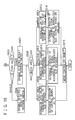
- Fig. 1 shows a configuration of a pointing device according to the first embodiment of the present invention.
- the pointing device comprises a slide key 1, hall elements 2 (2a, 2b, 2c, and 2d), a converting section 3, a calculating section 4, and a device processing section 5.
- the slide key 1 is a key placed at an opening section formed to a housing.
- the slide key 1 is held with an elastic body from at least three directions on a sliding plane so as to be normally located approximately at the center of the opening section.
- the slide key 1 is placed so as to slide on an opening plane (x-y plane).
- a magnet 11 is fixed to (built-in, embedded in, attached to, etc.) the slide key 1, and moves with the slide key 1.
- the hall elements 2 are sensors for detecting a variation of magnetic flux density generated with a move of the magnet 11, respectively.
- four hall elements 2a, 2b, 2c and 2d are set corresponding to a vertical direction and a horizontal direction of a display device where a controlled object is displayed.
- the 2a-2b direction and the 2c-2d direction are defined as x direction and y direction, respectively.
- the converting section 3 generates information indicating the position of the slide key 1 on an x-y coordinate system on the basis of the magnetic flux density detected by the respective hall elements 2. Namely, the converting section 3 converts the magnetic flux densities obtained as a result of the detection by the hall elements 2 into positional information of the slide key 1.
- the calculating section 4 calculates a slid distance and a slid direction of the slide key 1 using the x-y information generated by the converting section 3. Further, the calculating section 4 determines the strength of a control signal according to the slid distance of the slide key 1.
- the device processing section 5 performs the operations of generating a control signal with the strength determined by the calculating section 4, moving a controlled object (such as a cursor and a pointer) on a display screen (or changing the displayed position), and the like.
- the calculating section 4 comprises a direction area analyzing section 40, an area determining section 41, and a strength converting section 42.
- the direction area analyzing section 40 calculates a slid direction and a slid distance from the original point of the magnet 11 on the basis of the positional information of the magnet 11 calculated by the converting section 3.
- the area determining section 41 determines the area where the magnet 11 is located on the basis of the distance from the original point of the magnet 11, the distance being calculated by the direction area analyzing section 40. Incidentally, an explanation will be given of the areas set to the pointing device later.
- the strength converting section 42 generates information indicating the strength of a control signal (expressed as "P") on the basis of the positional information of the slide key 1 and the area information where the slide key 1 is located.
- the maximum slid distance and the minimum slid distance are defined as max _max and min _max, respectively. This deviation is generated since the initial position (original position) of the slide key 1 is not always placed at the center of the opening section.
- a user slides the slide key 1 until it reaches the rim of the opening section, and subsequently, slides it in a circular motion along the rim of the opening section. Otherwise, the user may slide the slide key 1 in main plural directions such as four directions above and below and right and left until the slide key reaches the rim of the opening section for simple setting.
- Fig. 2 shows definitions of the respective areas where the slide key 1 is slidable in the pointing device of the first embodiment.
- this embodiment there are set an undetectable area, a play area, an effective area, and a limiting area from the inside of the opening section.
- the center of the respective areas is placed at the center of the original point.
- the original point of the slide key 1 is a reference point for obtaining positional information of the slide key 1.
- the positional information generated by the converting section 3 is represented as, for example, (x, y) in the x-y coordinate system where the original point is determined as (0, 0). Accordingly, the slid distance of the slide key 1 is expressed as a distance from the original point to the (x, y) point (hereat, the distance is represented by "z"). Moreover, the slid direction of the slide key 1 is expressed as a direction from the original point toward the (x, y) point.
- the slid distance of the slide key 1 is represented as a size of a vector from the original point toward the (x, y) point
- the slid direction thereof is represented as a direction of a vector from the original point toward the (x, y) point.
- One of the methods is to obtain predetermined pieces of positional information of the slide key 1 at plural position in the state where the slide key 1 is not slid to calculate the average, and to calculate the position of the original point.
- predetermined pieces of positional information of the slide key 1 at the time of turning on the power may be obtained.
- predetermined pieces of positional information of the slide key 1 at the time of opening the folded electronic apparatus may be obtained.
- the respective areas described hereinbefore are determined by setting the original point thus calculated as a center. Incidentally, the position of the original point, information about the values of min _max and max _max and the like are stored in a memory (not shown).
- a pointing device may request a user to set again max _max and min _max according to need. For example, when setting again the original position, it is possible to display on a screen a message to urge a user to set again max _max and min _max when the positional deviation exceeds a predetermined amount (distance). Moreover, it is also possible for a user to set again max _max and min _max at an arbitrary timing.
- the undetectable area is an area for reducing power consumption of the pointing device.
- the hall elements 2 does not detect the changes of the magnetic flux densities as long as the slide key 1 is located within this area.
- the converting section 3, the calculating section 4 and the device processing section are not activated in this case.
- the play area is an area for preventing malfunction of the pointing device, and serves as play by which the pointing device does not generate a control signal just when something touches the slide key 1.
- the strength converting section 42 determines a strength of a control signal as "0".
- this area is effective in that, when the pointing device is provided with a push button function for detecting a push of a slide key 1, the pointing device does not detect displacement in a direction on the sliding plane accompanied by the push.
- the play area is defined by a circle whose center is the original point and whose radius is n/N of max _max (n and N are positive integers, and n ⁇ N).
- the size of the circle is determined on the basis of min _max or max _max.
- Min _max ⁇ ave _max ⁇ max _max.
- Min _max and max _max are variable values. Consequently, when a play area is set on the basis of min _max, the resultant area of the play area may be below a desired value. Therefore, it is necessary to set the play area on the basis of max _max.
- the radius of the play area when 38 % of max _max is set to the radius of the play area, the radius of the play area also becomes 0.3 mm or more. However, this is not preferable since the radius of the play area will be below the desired value when the position of the original point changes and the min _max becomes much smaller.
- the effective area is an area for enabling functions of the pointing device.
- the strength converting section 42 determines a strength of a control signal according to the slid distance of the slide key 1 on the basis of a predetermined rule of operation.
- the effective area is defined as a toric (circular) area where max _max . n/N ⁇ r ⁇ min _max (r: the distance from the original point).
- the limiting area is defined as a C-shaped area where min _max ⁇ r ⁇ max _max (r: the distance from the original point).
- the strength converting section 42 determines the strength of a control signal on the assumption that the slid distance of the slide key 1 is min _max.
- Fig. 3 shows a flow of operation when moving a controlled object on a display screen using the pointing device according to the first embodiment.
- the converting section 3 calculates positional information "X, Y" of the slide key 1 on the basis of the detected result of the magnetic flux density at the respective hall elements 2, and outputs the calculated positional information to the calculating section 4.
- the direction area analyzing section 40 calculates a slid distance "Z" of the magnet 11 on the basis of "X" and "Y”. Namely, the direction area analyzing section 40 converts the detected result of the magnetic flux density at the respective hall elements 2 into a slid distance and a resultant position of the slide key 1 (Step S102).
- the direction area analyzing section 40 outputs the slid distance "Z” of the slide key 1 to the area determining section 41.
- the direction area analyzing section 40 outputs the position "x, y" of the slide key 1 to the device processing section 5.
- the area determining section 41 determines the area where the slide key 1 is located on the basis of the slid distance "Z" of the slide key 1 (Step S103).
- the strength converting section 42 determines the strength of a control signal as "0" (Step S104). Moreover, when the slide key 1 is located within the effective area (Step S103/ EFFECTIVE AREA), the strength converting section 42 determines the strength of a control signal according to the slid distance of the slide key 1 (Step S105). Furthermore, when the slide key 1 is located within the limiting area (Step S103/ LIMITING AREA), the strength converting section 42 determines the strength of a control signal according to the slid distance on the assumption that the slid distance of the magnet 11 is min _max (Step S106).
- the device processing section 5 When the slide key 1 is located within the effective area or the limiting area, the device processing section 5 outputs a control signal corresponding to the slid direction of the slide key 1 with the strength determined by the strength converting section 42 to perform the processes of moving a controlled object on a display screen in the direction of "x, y", and the like (Step S107).
- Figs. 4A to 4E show examples of rules of operations when the strength converting section 42 transforms a slid distance of a slide key 1 into a strength of a control signal.
- the vertical axis denotes a strength of a control signal
- the horizontal axis denotes a slid distance of the slide key 1.
- Fig. 4A shows a case where the strength of a control signal is changed in proportion to the slid distance of the slide key 1 when the slide key 1 is located in the effective area.
- the strength of a control signal is "0".
- the strength of a control signal increases linearly from the initial value "P0".
- the strength converting section 42 stops the increase of the strength of a control signal, and does not increase the strength any more even when the slid distance further increases.
- the effective area may be divided into plural subareas to increase the strength of a control signal at a different ratio, respectively.
- Fig. 4B shows an example of the strength of a control signal when the effective area is divided into two subareas.
- the strength converting section 42 gradually increases the strength of a control signal when the slid slide key 1 reaches the effective area. After the slide key 1 reaches the outer subarea, the ratio of increase of the strength becomes large.
- the effective area may be subdivided.
- the strength converting section 42 may determine the strength of a control signal so as to keep a fixed value when the slide key 1 is located within the effective area as shown in Fig. 4E.
- the play area is set on the basis of max _max.
- a pointing device with good operationality.
- the direction area analyzing section 40 is included in the calculating section 4, it may be included in the converting section 3 or be independent from the respective sections.
- Fig. 5 shows a configuration of a pointing device according to the second embodiment.
- the pointing device of this embodiment comprises a slide key 1, hall elements 2, a converting section 3, a calculating section 4, and a device processing section 5 as with the first embodiment.
- the calculating section 4 of this embodiment further includes a normalizing section 43.
- the normalizing section 43 normalizes the slid distance of the slide key 1, the slid distance being generated by the converting section 3, to output the normalized value as "Zr".
- the device processing section 5 generates a control signal corresponding to the slid direction of the slide key 1 with the strength determined according to the normalized slid distance.
- the other sections operate in the same manner as described in the first embodiment.
- min _max and max _max vary according to respective pointing devices. Accordingly, the sizes of the play area, the effective area, and the like also vary according to respective pointing devices as shown in Fig. 7. Therefore, when the strength converting section 42 directly determines the strength of a control signal according to the slid distance of the slide key 1 (namely, the slid amount of the magnet 11), the maximum value of the control signal varies according to respective pointing devices, which leads to variations of operationality according to respective devices.
- the normalizing section 43 normalizes the slid distance of the slide key 1 and outputs it. Accordingly, it becomes possible to prevent the difference in operationality between respective devices.
- Fig. 8 shows an example of processes executed by the normalizing section 43.
- the normalizing section 43 normalizes the slid distance of the slide key 1 by converting the positional information of the slide key 1 into a quantized value of n bits (in this example, 8 bits), and outputs it.
- the distance from the original point to the boundary between the play area and the effective area is "31.5" in the pointing device A and "33" in the pointing device B.
- the normalizing section 43 in the respective devices A and B both converts the values into “85” and outputs it.
- the distance from the original point to the boundary between the effective area and the limiting area is "95" in the device A and "90” in the device B.
- the respective normalizing sections 43 convert the values into "255" and output it.
- the normalizing section 43 normalizes the slid distance of the slide key 1 with serial values so as to output "0" at the original point, "85” at the boundary between the play area and the effective area, and "225" at the boundary between the effective area and the limiting area. Moreover, when the slide key 1 is positioned within the limiting area, the normalizing section 43 converts the slid distance of the slide key 1 into "255" for normalization.
- the normalizing section 43 converts the positional information of the slide key 1 into a quantized value. Accordingly, it becomes possible to achieve the same operationality regardless of different pointing devices.
- Fig. 9 shows a flow of operation when moving a controlled object using the pointing device according to the second embodiment.
- the Steps S201 to S203 are the same as the Steps S101 to S103 as shown in Fig. 3 in the first embodiment.
- Step S203 determines that the slide key 1 is located in the play area
- the normalizing section 43 outputs a normalized value according to the positional information of the slide key 1
- the strength converting section 42 determines the strength of a control signal as "0" (Step S205).
- the normalizing section 43 converts the slid distance of the slide key 1 into a normalized value (Step S206). Subsequently, the strength converting section 42 determines the strength of a control signal according to the normalized slid distance of the slide key 1 on the basis of a predetermined rule of operation (Step S207).
- the normalizing section 43 When the area determining section 41 determines that the slide key 1 is located in the limiting area (Step S203/ LIMITING AREA), the normalizing section 43 outputs a normalized value on the assumption that the slid distance of the slide key 1 is min _max (Step S208). Subsequently, the strength converting section 42 determines the strength of a control signal according to the normalized slid distance on the assumption that the slid distance is min _max (Step S209).
- the device processing section 5 When the slide key 1 is located within the effective area or the limiting area, the device processing section 5 outputs a control signal corresponding to the slid direction of the slide key 1 with the strength determined by the strength converting section 42 to execute processes of moving a controlled object on a display screen, and the like (Step S210).
- Fig. 10 shows a configuration of a pointing device according to the third embodiment.
- the pointing device comprises a slide key 1, hall elements 2, a converting section 3, a calculating section 4, a device processing section 5 and a temperature sensor 6.
- the calculating section 4 further includes a temperature correcting section 44 in addition to the configuration of the pointing device in the second embodiment.
- the temperature correcting section 44 corrects the difference in sensitivity of the hall elements 2 according to the changes in temperature of an environment where the pointing device is used.
- the temperature sensor 6 is a sensor for measuring a temperature of an environment where the pointing device is used.
- the slid direction and the slid distance of the slide key 1 are detected using the magnet 11 and the hall elements 2.
- the magnetic flux density detected by the respective hall elements 2 changes even if the slide key 1 is moved by the same distance.
- the higher the temperature of the environment where the pointing device is used the more the magnetic flux density detected by the respective hall elements 2 is reduced. Consequently, it is necessary to correct a slid distance of the slide key 1 according to the temperature of the environment where the pointing device is used. Otherwise, variations are generated in the strength determined by the strength converting section 42 and in operationality.
- the temperature correcting section 44 corrects the slid distance of the slide key 1 on the basis of a detected result of the temperature sensor 6. By this means, it becomes possible to generate the same control signal regardless of changes in temperature where the pointing device is used.
- the operation of the pointing device of the third embodiment is the same as that in the second embodiment except that the temperature correcting section 44 corrects the slid distance "Z" of the slide key 1, which is an output from the direction area analyzing section 40.
- the pointing device according to the third embodiment it becomes possible not only to obtain the same effects as those obtained in the second embodiment but also to achieve the same operationality regardless of the temperature where the pointing device is used.
- Fig. 11 shows a configuration of a pointing device according to the fourth embodiment.
- the pointing device comprises a slide key 1, hall elements 2, a converting section 3, a calculating section 4, a device processing section 5, a temperature sensor 6, and a storing section 7.
- the storing section 7 stores a plurality of rules of operations used when the strength converting section 42 transforms a slid distance of the slide key 1 into a strength of a control signal.
- the other sections operate in the same manner as in the third embodiment.
- Fig. 12 shows an example of a rule of operation stored in the storing section 7.
- the vertical axis denotes a strength of a control signal
- the horizontal axis is a normalized slid distance.
- a user can select a suitable rule of operations from the plural rules stored in the storing section 7 to customize the operationality of the pointing device.
- Fig. 13 shows a configuration of a pointing device according to the fifth embodiment.
- the pointing device comprises a slide key 1, hall elements 2, a converting section 3, a calculating section 4, a device processing section 5, a temperature sensor 6 and a storing section 7 and a decision switch 8.
- the slide key 1 has a function as a push button.
- the decision switch 8 is a switch for detecting a push of the slide key 1.
- the other sections operate in the same manner as in the fourth embodiment.
- the slide key When the slide key is provided with a function as a push button like the pointing device of this embodiment, a user may wrongly push the slide key 1 while intending to slide it. Therefore, when the slid distance of the slide key 1 is a predetermined value or more, it is preferable that the decision switch 8 disables a push of the slide key 1 in view of operationality even if the decision switch 8 detects the push.
- Fig. 14 shows definitions of areas where the slide key 1 is slidable in the pointing device of this embodiment.
- a push valid area to enable the detected result of the decision switch 8 is provided in addition to respective areas as shown in Fig. 2 in the first embodiment.
- the push valid area is defined as a circular area with a radius of m/N of max _max (m is an arbitrary positive integer, and m ⁇ N), and the center of the circular area is the original point.
- the push valid area is determined on the basis of max _max in the same manner as determining the play area as explained in the first embodiment. Accordingly, it becomes possible to secure a minimum radius to obtain a required push valid area.
- the push valid area is an area overlapped with the other area(s), namely, the push valid area is not independent from the other area(s). Accordingly, when overlapped with the other area(s), the push valid area has both characteristics of the respective areas.
- Figs. 15 and 16 show a flow of operation when moving a controlled object displayed on a screen using the pointing device of the fifth embodiment.
- Step S501 When a user slides the slide key 1, the magnet 11 moves with the slide key 1 and the magnetic flux density detected by the respective hall elements 2 changes (Step S501).
- the converting section 3 calculates positional information of the slide key 1 on the basis of the detected result of the magnetic flux density detected by the respective hall elements 2, and outputs the calculated information to the calculating section 4.
- the direction area analyzing section 40 calculates the distance (slid amount) "Z" on the basis of the positional information of the slide key 1. Subsequently, the direction area analyzing section 40 outputs the slid distance "Z" of the slide key 1 to the temperature correcting section 44. Moreover, the analyzing section 40 outputs the position "x, y" of the slide key 1 to the device processing section 5 (Step S502).
- the temperature correcting section 44 corrects the distance of the slide key 1 on the basis of the detected result of the temperature sensor 6 so as to indicate a value obtained under a predetermined temperature (for example, 20°C) (Step S503), and outputs the corrected value to the area determining section 41.
- a predetermined temperature for example, 20°C
- the area determining section 41 determines the area where the slide key 1 is located on the basis of the distance of the slide key 1 (Step S504).
- the area determining section 41 transmits a signal to disable the detected result of the decision switch 8 to the device processing section 5, and disables the detected result (Step S506). Namely, when the slide key 1 is not located in the push valid area, the device processing section 5 does not execute processes associated with the push of the slide key 1 even when the decision switch 8 detects the push of the slide key 1.
- the area determining section 41 transmits a signal to enable the detected result of the decision switch 8 to the device processing section 5, and enables the detected result (Step S507).
- the device processing section 5 performs the controls associated with the push of the slide key 1 when the decision switch 8 detects the push of the slide key 1.
- Step S510 when the area determining section 41 determines that the slide key 1 is located in the play area as a result of area determination (Step S508/PLAY AREA), while the normalizing section 43 outputs a normalized value according to the positional information of the magnet 11 (Step S509), the strength converting section 42 determines the strength of a control signal as "0" (Step S510).
- the normalizing section 43 converts the slid distance of the slide key 1 into a normalized value (Step S511).
- the strength converting section 42 determines the strength of a control signal according to the normalized slid distance of the slide key 1 (Step S512).
- the normalizing section 43 When the area determining section 41 determines that the slide key 1 is located in the limiting area (Step S508/ LIMITING AREA), the normalizing section 43 outputs a normalized value on the assumption that the slid distance of the slide key 1 is min _max (Step S513). Subsequently, the strength converting section 42 determines the strength of a control signal according to the normalized value on the assumption that the slid distance of the slide key 1 is min _max (Step S514).
- the device processing section 5 When the slide key 1 is located in the effective area or the limiting area, the device processing section 5 outputs a control signal corresponding to the slid direction of the slide key 1 with the strength determined by the strength converting section 42 to execute processes of moving a controlled object on a screen, and the like (Step S515).
- the push valid area is defined as a circular area with an arbitrary radius which satisfies 0 ⁇ m ⁇ N, it is preferable that the size of the push valid area is approximately identical to the size of the play area (namely, n ⁇ m).
- Fig. 17 shows an example of a flow in this case.
- the area determining section 41 transmits a signal to enable the detected result of the decision switch 8 to the device processing section 5, and enables the detected result (Step S506'). Namely, in the case where the slide key 1 is located in the play area, the device processing section 5 executes controls associated with the push of the slide key when the decision switch 8 detects a push of the slide key 1.
- Step S507' the normalizing section 43 outputs a normalized value according to the positional information of the magnet 11 (Step S507')
- the strength converting section 42 determines the strength of a control signal as "0" (Step S508').
- the area determining section 41 transmits a signal to disable the detected result by the decision switch 8 to the device processing section 5, and disables the detected results (Step S509'). Namely, in the case where the slide key 1 is located in the effective area, the device processing section 5 does not execute controls associated with the push of the slide key 1 even when the decision switch 8 detects the push of the slide key 1.
- the normalizing section 43 converts the slid distance of the slide key 1 into a normalized value (Step S510').
- the strength converting section 42 determines the strength of a control signal according to the normalized slid distance of the slide key 1 (Step S511').
- the area determining section 41 transmits a signal to disable the detected result of the decision switch 8 to the device processing section 5, and disables the detected result (Step S512'). Namely, in the case where the slide key is located in the limiting area, the device processing section 5 does not execute controls associated with the push of the slide key 1 even when the decision switch 8 detects the push of the slide key 1.
- the normalizing section 43 outputs a normalized value on the assumption that the slid distance of the slide key 1 is min _max (Step S513').
- the strength converting section 42 determines the strength of a control signal according to the normalized value on the assumption that the slid distance of the slide key 1 is min _max (Step S514').
- the device processing section 5 When the slide key 1 is located in the effective area or the limiting area, the device processing section 5 outputs a control signal corresponding to the slid direction of the slide key 1 with the strength determined by the strength converting section 42 to execute processes of moving a controlled object on a screen, and the like (Step S515').
- the pointing device As described above, in the pointing device according to the fifth embodiment, it becomes possible not only to obtain the same effects as those obtained in the fourth embodiment but also to prevent malfunctions of the slide key 1 as a push button.
- Fig. 18 shows a construction of a pointing device according to the sixth embodiment.
- the pointing device comprises a slide key 1, hall elements 2, a converting section 3, a calculating section 4, a device processing section 5, a temperature sensor 6, a storing section 7 and a decision switch 8.
- the hall elements 2 are placed such that the hall elements 2 are displaced at a predetermined angle to a vertical line and a horizontal line of a screen where a controlled object is displayed.
- the calculating section 4 further includes a coordinate converting section 45. The configuration and the operation of the other sections are the same as those in the fifth embodiment.
- the hall elements 2 are placed on a vertical line and a horizontal line of the screen of a displaying device where a controlled object is displayed as shown in Fig. 19A.
- the substrate (printed circuit board) where the hall elements 2 are mounted may become large in area, which is an obstacle to miniaturization of an electronic apparatus where the pointing device is mounted.
- the hall elements 2 are placed at a predetermined angle (for example, 45 degrees) to the vertical line and the horizontal line of the screen where a controlled object is displayed as shown in Fig. 19B.
- a predetermined angle for example, 45 degrees
- the positional information of the slide key 1 calculated by the converting section 3 are expressed as a value on the basis of the coordinate axes composed of the lines (2a-2b line, 2c-2d line) where the hall elements 2 are placed as shown in Fig. 19B. Accordingly, it is impossible to convert the positional information into control information (a control signal) corresponding to the vertical line and horizontal line of the display.
- the coordinate converting section 45 converts the positional information of the slide key 1 into information corresponding to the vertical and horizontal lines of the display of a displaying device.
- Fig. 20 shows coordinate-axes converting processes executed by the coordinate converting section 45.
- the converting section 3 converts the detected result of magnetic flux density of the respective hall elements 2 into positional information (X, Y) on the basis of coordinate axes composed of the 2a-2b line (y direction) of the hall elements 2a and 2b and the 2c-2d line (x direction) of the hall elements 2c and 2d.
- the coordinate converting section 45 converts the acquired information into positional information (X', Y') on the basis of coordinate axes composed of a vertical line (y' direction) and a horizontal line (x' direction) of the display, and outputs the positional information (X', Y') to the direction area analyzing section 40.
- the strength converting section 42 requires information of the slid distance and the slid direction of the slide key 1 to determine the strength of a control signal. Accordingly, once the slid distance (Z') is calculated, the slid direction can be determined as long as the ratio of X' to Y' is gained. In this case, there is no need to retain the absolute value of the X' and Y'. Therefore, the direction area analyzing section 40 converts the X' and Y' into values X" and Y" on a unit circle.
- the pointing device executes the same process as those in the fifth embodiment.
- Figs. 21, 22 and 23 show a flow of operation when the pointing device of the sixth embodiment generates a control signal for a controlled object.
- This operation is the same as that of the fifth embodiment except that the positional information of the magnet 11 is converted into positional information in a coordinate system corresponding to the vertical direction and the horizontal direction of the display screen at Step S602.
- the pointing device in the pointing device according to the sixth embodiment, it becomes possible not only to obtaining the same effects as those obtained in the fifth embodiment but also to generate a control signal even when a slid direction and a slid distance of the slide key 1 are not expressed in a certain coordinate system (for example, a coordinate system where the slid direction and the slid distance are expressed in coordinate axes corresponding to a vertical direction and a horizontal direction of a display screen).
- a certain coordinate system for example, a coordinate system where the slid direction and the slid distance are expressed in coordinate axes corresponding to a vertical direction and a horizontal direction of a display screen.
- Fig. 24 is a block diagram showing a pointing device according to the seventh embodiment.
- the pointing device further includes a strength control circuit 50 for adjusting the strength of a control signal, the strength being determined at the strength converting section 42, in addition to the same configuration as that of the pointing device of the first embodiment.
- the strength control circuit 50 changes the strength of a control signal so as to change, according to the display screen, a velocity of moving a controlled object (for example, a pointer such as a cursor) on a screen in the direction of "X, Y".
- the strength control circuit 50 generates a strength control signal 502 on the basis of a display screen information 500, and a control signal 503 on the basis of a user setting signal 501.
- the strength converting section 42 changes the strength of a control signal to be output to the device processing device 5 on the basis of the strength control signal 502 and the control signal 503. Subsequently, the device processing section 5 moves the pointer on the display screen on a displaying section (not shown) on the basis of the received control signal.
- the display screen information 500 is information indicating a kind of a display screen, for example, whether a moving range of the pointer is large or small on a display screen.
- the strength control circuit 50 When the display screen information 500 indicates that the pointer has a large moving range on the display screen, the strength control circuit 50 generates a strength control signal 502 for accelerating a moving velocity of the pointer than usual. On the other hand, when the display screen information 500 indicates that the pointer has a small moving range on the display screen, the strength control circuit 50 generates a strength control signal 502 for slowing a moving velocity of the pointer than usual. By accelerating and slowing a moving velocity of the pointer according to the display screen information 500 indicating a moving range of the pointer, it becomes possible to improve the operationality of the pointing device.
- the display screen information 500 may be information indicating whether the size of a controlled object to be selected by the pointer is large or small on the display screen.
- the strength control circuit 50 When the display screen information 500 indicates that the controlled object to be selected by the pointer is large on the display screen, the strength control circuit 50 generates a strength control signal 502 for accelerating a moving velocity of the pointer (or for keeping a moving velocity as usual). On the other hand, when the display screen information 500 indicates that the controlled object to be selected by the pointer is small on the display screen, the strength control circuit 50 generates a strength control signal 502 for slowing a moving velocity of the pointer than usual. By accelerating and slowing a moving velocity of the pointer according to the display screen information 500 indicating a size of a controlled object to be selected by the pointer, it becomes possible to improve the operationality of the pointing device.
- the display screen information 500 may be information indicating, for example, one of the four types of the screen: a usual screen at the time of communication, stand-by state, and the like; a main menu screen for selecting a menu from plural menus; a screen for inputting symbols (characters, figures, pictorial symbols, etc.); and a screen indicating some kind of application is in execution.
- the strength control circuit 50 generates a different strength control signal 502 according to the display screen information 500 to change a moving velocity of the pointer on the screen according to the display screen information 500.
- the user setting signal 501 is generated on the basis of user settings (which the user sets by operating buttons (not shown) and the pointing device) with respect to each display screen when in a mode for setting a moving velocity of the pointer (pointer velocity setting mode).
- the strength control circuit 50 when in the pointer velocity setting mode, the strength control circuit 50 generates a control signal 503 for changing a rule of operation (a function showing strength of a control signal to a slid distance of the slide key 1 as shown in Figs. 4A to 4E), which is used when the strength converting section 42 determines the strength of a control signal, on the basis of the user setting signal 501 with respect to each display screen information 500.
- a rule of operation a function showing strength of a control signal to a slid distance of the slide key 1 as shown in Figs. 4A to 4E
- the user setting signal 501 is initial-velocity setting information, low-velocity setting information, and high-velocity setting information for adjusting "initial velocity (velocity when starting a motion)", “low velocity (acceleration from the initial velocity)", and “high velocity (acceleration from the low velocity)” of the pointer on a display screen with plural levels (for example, twelve levels), respectively.
- the velocity of the pointer is adjustable with twelve levels, a user can set the initial velocity of the pointer on a display screen to "2", the low velocity to "4", and the high velocity to "8” by operating buttons (not shown) and the slide key 1 when in the pointer velocity setting mode.
- the strength control circuit 50 generates a control signal 503 for converting a rule of operation used by the strength converting section 42 on the basis of the user setting signal 501 (the above-described initial-velocity setting information, low-velocity setting information, and high-velocity setting information). Accordingly, the strength converting section 42 can change a rule of converting operation at respective timings in phase. Namely, by transmitting the control signal 503 from the strength control circuit 50 to the strength converting section 42, it becomes possible to change a conversion rule, which is used when the strength converting section 42 determines the strength of a control signal according to a slid distance of the slid key 1, according to the user setting signals 501. By this means, it becomes possible to accelerate or slow a moving velocity of the pointer according to the user settings, thereby achieving the improved operationality of the pointing device.
- the pointing device of the seventh embodiment further includes the strength control circuit 50 in addition to the configuration of the first embodiment
- the pointing device of the other embodiments may include the strength control circuit 50 to change the strength of a control signal according to a display screen.
- the strength control circuit 50 may be included in the calculating section 4.
- a display position of a controlled object displayed on a display screen of a displaying device is moved with the pointing device
- the pointing device and a display device may be combined as shown in Fig. 25.
- an electronic apparatus provided with the pointing device of the present invention can change a display section of a controlled object on a display screen by the same operations as those described in the respective embodiments.
- a slide key may be provided with an optically readable mark to be read by CCD, etc. to detect a slid direction and a slid distance of the slide key.
- the number of the hall elements are not limited to four as long as the position of the slide key can be identified.
- the rules of operations for transforming a slid distance of a slide key into a strength of a control signal are not limited to those shown in the above embodiments. Namely, any rule can be employed as long as a slid distance can be uniquely transformed into a strength of a control signal.
- control signal generated by the pointing device is not necessarily a signal for changing a display position of a controlled object displayed on a screen.
- the present invention can be diversely changed and modified.
- a pointing device capable of generating a fixed signal regardless of operated directions and preventing malfunctions of generating a control signal when an operating section (slide key) is not slid even when an initial point of the operating section is not located at the center of an opening section.
Landscapes
- Engineering & Computer Science (AREA)
- General Engineering & Computer Science (AREA)
- Theoretical Computer Science (AREA)
- Human Computer Interaction (AREA)
- Physics & Mathematics (AREA)
- General Physics & Mathematics (AREA)
- Position Input By Displaying (AREA)
- Input From Keyboards Or The Like (AREA)
Abstract
Description
- the pointing device disables the push of the operation key detected by the push switch when the operation key is located outside a circular area whose center is the original point and whose radius is m/N of the max _max (m is an arbitrary positive integer, and m < N).
Claims (20)
- A pointing device for detecting a slid distance and a slid direction of an operation key located approximately at the center of an opening section to generate a control signal according to the detected slid distance and the slid direction, wherein:when an original point is defined as a point where a slid distance of the operation key is zero, and a maximum value and a minimum value are defined as max _max and min _max, respectively, in the state where the operation key is moved until reaching the rim of the opening section, the pointing device generates the control signal corresponding to the slid distance of the operation key by:determining a strength of the control signal as zero in the case where the operation key is located within a circular area whose center is located at the original point and whose radius is n/N of the max _max (n and N are arbitrary positive integers, and n < N);determining a strength of the control signal corresponding to the slid distance of the operation key on the basis of a predetermined rule of operation in the case where the operation key is located within a toric area whose distance from the original point is larger than n/N of the max _max and smaller than the min _max; ordetermining a strength of the control signal corresponding to a strength obtained when a slid distance of the operation key is the min _max in the case where the operation key is located within an area whose distance from the original point is larger than the min _max.
- A pointing device as claimed in claim 1, comprising a plurality of rules of operations for transforming the slid distance of the operation key into the strength of the control signal.
- A pointing device as claimed in claim 1 or 2, wherein:the toric area is divided into a plurality of subareas by setting at least one circular arc as a boundary whose center is the original point; andthe respective subareas have different variations of the strength of the control signal to the slid distance of the operation key.
- A pointing device for detecting a slid distance and a slid direction of an operation key located approximately at the center of an opening section, generating signal strength information on the basis of the slid distance of the operation key, and generating a control signal corresponding to the signal strength information and the slid direction of the operation key, wherein:when an original point is defined as a point where a slid distance of the operation key is zero, and a maximum value and a minimum value are defined as max _max and min _max, respectively, in the state where the operation key is moved until reaching the rim of the opening section, the pointing device generates:signal strength information for determining a strength of the control signal as zero in the case where the operation key is located within a circular area whose center is located at the original point and whose radius is n/N of the max _max (n and N are arbitrary positive integers, and n < N);signal strength information on the basis of a predetermined rule of operation so that a strength of the control signal corresponds to the slid distance of the operation key in the case where the operation key is located within a toric area whose distance from the original point is larger than n/N of the max _max and smaller than the min _max; orsignal strength information for determining a strength of the control signal so as to be identical to the strength when a slid distance of the operation key is the min _max in the case where the operation key is located within an area whose distance from the original point is larger than the min _max; anda strength of the control signal is fixed regardless of a slid direction of the operation key when the operation key is located at the position where a distance from the original point is the min _max.
- A pointing device as claimed in claim 4, comprising a plurality of rules of operations for transforming the slid distance of the operation key into the signal strength information.
- A pointing device as claimed in claim 4 or 5, wherein:the toric area is divided into a plurality of subareas by setting at least one circular arc as a boundary whose center is the original point; andthe respective subareas have different variations of the signal strength information to the slid distance of the operation key.
- A pointing device as claimed in any of claims 1 to 6, further comprising:a section for measuring a temperature of an environment where the pointing device is used; anda section for correcting the detected slid distance of the operation key according to the temperature.
- A pointing device as claimed in any of claims 1 to 7, further comprising:a push switch for detecting a push of the operation key, wherein:the pointing device disables the push of the operation key detected by the push switch when the operation key is located outside a circular area whose center is the original point and whose radius is m/N of the max _max (m is an arbitrary positive integer, and m < N).
- A pointing device as claimed in any of claims 1 to 8, wherein:the operation key is provided with a plurality of hall elements in the vicinity of the opening section; andthe pointing device detects the slid direction and the slid distance of the operation key on the basis of magnetic flux density detected by the respective hall elements.
- A pointing device as claimed in any of claims 1 to 9, wherein:when the slid distance and the slid direction of the operation key is expressed in a coordinate system different from a coordinate system used for a control signal, the pointing device converts the slid distance and the slid direction of the operation key into a slid distance and a slid direction expressed in the same coordinate system as used for the control signal.
- An electronic apparatus comprising a pointing device for detecting a slid distance and a slid direction of an operation key located approximately at the center of an opening section to generate a control signal according to the detected slid distance and the slid direction, and a display section for displaying information, wherein:when an original point is defined as a point where a slid distance of the operation key is zero, and a maximum value and a minimum value are defined as max _max and min _max, respectively, in the state where the operation key is moved until reaching the rim of the opening section, the pointing device generates the control signal corresponding to the slid distance of the operation key by:determining a strength of the control signal as zero in the case where the operation key is located within a circular area whose center is located at the original point and whose radius is n/N of the max _max (n and N are arbitrary positive integers, and n < N);determining a strength of the control signal corresponding to the slid distance of the operation key on the basis of a predetermined rule of operation in the case where the operation key is located within a toric area whose distance from the original point is larger than n/N of the max _max and smaller than the min _max; ordetermining a strength of the control signal corresponding to a strength obtained when a slid distance of the operation key is the min _max in the case where the operation key is located within an area whose distance from the original point is larger than the min _max; anda display position of a controlled object displayed on the display section is changed on the basis of the control signal.
- An electronic apparatus as claimed in claim 11, comprising a plurality of rules of operations for transforming the slid distance of the operation key into the strength of the control signal.
- An electronic apparatus as claimed in claim 11 or 12, wherein:the toric area is divided into a plurality of subareas by setting at least one circular arc as a boundary whose center is the original point; andthe respective subareas have different variations of the strength of the control signal to the slid distance of the operation key.
- An electronic apparatus comprising a pointing device for detecting a slid distance and a slid direction of an operation key located approximately at the center of an opening section, generating signal strength information on the basis of the slid distance of the operation key, and generating a control signal corresponding to the signal strength information and the slid direction of the operation key, and a display section for displaying information, wherein:when an original point is defined as a point where a slid distance of the operation key is zero, and a maximum value and a minimum value are defined as max _max and min _max, respectively, in the state where the operation key is moved until reaching the rim of the opening section, the pointing device generates:signal strength information for determining a strength of the control signal as zero in the case where the operation key is located within a circular area whose center is located at the original point and whose radius is n/N of the max _max (n and N are arbitrary positive integers, and n < N);signal strength information on the basis of a predetermined rule of operation so that a strength of the control signal corresponds to the slid distance of the operation key in the case where the operation key is located within a toric area whose distance from the original point is larger than n/N of the max _max and smaller than the min _max; orsignal strength information for determining a strength of the control signal so as to be identical to the strength when a slid distance of the operation key is the min _max in the case where the operation key is located within an area whose distance from the original point is larger than the min _max; anda strength of the control signal is fixed regardless of a slid direction of the operation key when the operation key is located at the position where a distance from the original point is the min _max; anda display position of a controlled object displayed on the display section is changed on the basis of the control signal.
- An electronic apparatus as claimed in claim 14, comprising a plurality of rules of operations for transforming the slid distance of the operation key into the signal strength information.
- An electronic apparatus as claimed in claim 14 or 15, wherein:the toric area is divided into a plurality of subareas by setting at least one circular arc as a boundary whose center is the original point; andthe respective subareas have different variations of the signal strength information to the slid distance of the operation key.
- An electronic apparatus as claimed in any of claims 11 to 16, further comprising:a section for measuring a temperature of an environment where the pointing device is used; anda section for correcting the detected slid distance of the operation key according to the temperature.
- An electronic apparatus as claimed in any of claims 11 to 17, further comprising:a push switch for detecting a push of the operation key, wherein:the pointing device disables the push of the operation key detected by the push switch when the operation key is located outside a circular area whose center is the original point and whose radius is m/N of the max _max (m is an arbitrary positive integer, and m < N).
- An electronic apparatus as claimed in any of claims 11 to 18, wherein:the operation key is provided with a plurality of hall elements in the vicinity of the opening section; andthe pointing device detects the slid direction and the slid distance of the operation key on the basis of magnetic flux density detected by the respective hall elements.
- An electronic apparatus as claimed in any of claims 11 to 19, wherein:when the slid distance and the slid direction of the operation key is expressed in a coordinate system different from a coordinate system used for a control signal, the pointing device converts the slid distance and the slid direction of the operation key into a slid distance and a slid direction expressed in the same coordinate system as used for the control signal.
Applications Claiming Priority (2)
| Application Number | Priority Date | Filing Date | Title |
|---|---|---|---|
| JP2002341428 | 2002-11-25 | ||
| JP2002341428A JP4167477B2 (en) | 2002-11-25 | 2002-11-25 | Pointing device and electronic equipment |
Publications (3)
| Publication Number | Publication Date |
|---|---|
| EP1422603A2 true EP1422603A2 (en) | 2004-05-26 |
| EP1422603A3 EP1422603A3 (en) | 2006-11-15 |
| EP1422603B1 EP1422603B1 (en) | 2014-04-02 |
Family
ID=32212166
Family Applications (1)
| Application Number | Title | Priority Date | Filing Date |
|---|---|---|---|
| EP03026808.0A Expired - Lifetime EP1422603B1 (en) | 2002-11-25 | 2003-11-20 | Pointing device and electronic apparatus provided with the pointing device |
Country Status (4)
| Country | Link |
|---|---|
| US (1) | US7187360B2 (en) |
| EP (1) | EP1422603B1 (en) |
| JP (1) | JP4167477B2 (en) |
| CN (1) | CN100378627C (en) |
Cited By (1)
| Publication number | Priority date | Publication date | Assignee | Title |
|---|---|---|---|---|
| WO2009072848A3 (en) * | 2007-12-05 | 2009-09-24 | Eui Jin Oh | Data input device |
Families Citing this family (38)
| Publication number | Priority date | Publication date | Assignee | Title |
|---|---|---|---|---|
| US7429976B2 (en) * | 2003-11-24 | 2008-09-30 | Avago Technologies Ecbu Ip (Singapore) Pte. Ltd. | Compact pointing device |
| US7570247B2 (en) * | 2003-11-24 | 2009-08-04 | Avago Technologies Ecbu Ip (Singapore) Pte. Ltd. | Modular assembly for a self-indexing computer pointing device |
| JP2005321975A (en) * | 2004-05-07 | 2005-11-17 | Sony Corp | Information processor and control method therefor |
| US7978173B2 (en) * | 2005-01-14 | 2011-07-12 | Avago Technologies Ecbu Ip (Singapore) Pte. Ltd. | Pointing device including a moveable puck with mechanical detents |
| US20060170654A1 (en) * | 2005-02-02 | 2006-08-03 | Delphi Technologies, Inc. | No tilt joystick with CCD sensing |
| US7586480B2 (en) | 2005-02-28 | 2009-09-08 | Avago Technologies Ecbu Ip (Singapore) Pte. Ltd. | Hybrid pointing device |
| US7710403B2 (en) * | 2005-04-26 | 2010-05-04 | Avago Technologies Ecbu Ip (Singapore) Pte. Ltd. | Slide pad membrane |
| KR100735558B1 (en) * | 2005-10-18 | 2007-07-04 | 삼성전자주식회사 | Apparatus and method for displaying pointer |
| US20070091066A1 (en) * | 2005-10-24 | 2007-04-26 | Jonah Harley | Slide pad system and method with hybrid mode |
| US7701440B2 (en) * | 2005-12-19 | 2010-04-20 | Avago Technologies Ecbu Ip (Singapore) Pte. Ltd. | Pointing device adapted for small handheld devices having two display modes |
| JP4871013B2 (en) * | 2006-04-17 | 2012-02-08 | 株式会社ソニー・コンピュータエンタテインメント | Information processing apparatus, control method thereof, and program |
| US20070247446A1 (en) * | 2006-04-25 | 2007-10-25 | Timothy James Orsley | Linear positioning input device |
| US7889176B2 (en) * | 2006-07-18 | 2011-02-15 | Avago Technologies General Ip (Singapore) Pte. Ltd. | Capacitive sensing in displacement type pointing devices |
| US20080024441A1 (en) * | 2006-07-25 | 2008-01-31 | Jonah Harley | Displacement type pointing device and method |
| US9141230B2 (en) | 2006-08-30 | 2015-09-22 | Avaoo Technologies General IP (Singapore) Pte. Ltd. | Optical sensing in displacement type input apparatus and methods |
| US7639234B2 (en) * | 2007-01-04 | 2009-12-29 | Avago Technologies Ecbu Ip (Singapore) Pte. Ltd. | Capacitive sensing and absolute position mapping in displacement type pointing devices |
| JP4945285B2 (en) * | 2007-03-29 | 2012-06-06 | 株式会社日立製作所 | Cursor operation device |
| JP4787782B2 (en) * | 2007-03-30 | 2011-10-05 | 富士通コンポーネント株式会社 | Equipment operation system, control device |
| JP5005413B2 (en) * | 2007-04-09 | 2012-08-22 | 株式会社東海理化電機製作所 | In-vehicle device controller |
| US20090058802A1 (en) * | 2007-08-27 | 2009-03-05 | Avago Technologies Ecbu Ip (Singapore) Pte. Ltd. | Input device |
| US8232963B2 (en) * | 2007-08-27 | 2012-07-31 | Avago Technologies Ecbu Ip (Singapore) Pte. Ltd. | Control and data entry apparatus |
| US7978175B2 (en) * | 2007-11-23 | 2011-07-12 | Avago Technologies Ecbu Ip (Singapore) Pte. Ltd. | Magnetic re-centering mechanism for a capacitive input device |
| US20090135157A1 (en) * | 2007-11-27 | 2009-05-28 | Avago Technologies Ecbu Ip (Singapore) Pte. Ltd. | Capacitive Sensing Input Device with Reduced Sensitivity to Humidity and Condensation |
| KR101114212B1 (en) | 2007-12-13 | 2012-03-07 | 삼성테크윈 주식회사 | Slide pad system and method of controlling the same |
| JP5621199B2 (en) | 2008-04-24 | 2014-11-05 | 住友電気工業株式会社 | Si (1-vwx) CwAlxNv substrate manufacturing method, epitaxial wafer manufacturing method, Si (1-vwx) CwAlxNv substrate and epitaxial wafer |
| CN101581990B (en) * | 2008-05-13 | 2011-12-07 | 联想(北京)有限公司 | Electronic equipment as well as wearable pointing device and method applied to same |
| US20100045598A1 (en) * | 2008-08-20 | 2010-02-25 | Honeywell International Inc. | Apparatus for controlling the movement of an object on a plane |
| JP2010055387A (en) * | 2008-08-28 | 2010-03-11 | Nec Corp | Portable information terminal and control method thereof |
| JP5381630B2 (en) * | 2009-11-13 | 2014-01-08 | 日本電気株式会社 | Character input device, portable terminal device, character input detection method, and program |
| DE102010019596A1 (en) | 2010-05-05 | 2011-11-10 | Fm Marketing Gmbh | Input device, has coils attached on circuit board and connected with oscillator, where output signal of oscillator has frequency that is dependent on relative position of movable magnetic part towards coil |
| DE102010012247A1 (en) | 2010-03-22 | 2011-09-22 | Fm Marketing Gmbh | Input device for e.g. computer, has inductors formed as coil that is connected with oscillator, where output signal of oscillator has frequency based on relative position of movable magnets to coil |
| WO2011116929A1 (en) | 2010-03-22 | 2011-09-29 | Fm Marketing Gmbh | Input apparatus with haptic feedback |
| US9296299B2 (en) * | 2011-11-16 | 2016-03-29 | Autoconnect Holdings Llc | Behavioral tracking and vehicle applications |
| DE102011014763A1 (en) * | 2011-03-22 | 2012-09-27 | Fm Marketing Gmbh | Input device with haptic feedback |
| JP6482771B2 (en) | 2014-04-22 | 2019-03-13 | 任天堂株式会社 | Information processing apparatus, information processing system, information processing program, and information processing method |
| WO2016031028A1 (en) * | 2014-08-28 | 2016-03-03 | 任天堂株式会社 | Information-processing terminal and game device |
| TWI552892B (en) * | 2015-04-14 | 2016-10-11 | 鴻海精密工業股份有限公司 | Control system and control method for vehicle |
| EP3444016A1 (en) * | 2017-08-17 | 2019-02-20 | Bigben Interactive SA | Method for controlling a display element by a game console |
Family Cites Families (16)
| Publication number | Priority date | Publication date | Assignee | Title |
|---|---|---|---|---|
| US5627767A (en) * | 1995-02-24 | 1997-05-06 | Atoma International, Inc. | Testing device for manually movable components of a motor vehicle |
| JP3793277B2 (en) | 1996-03-18 | 2006-07-05 | 富士通コンポーネント株式会社 | Cursor position indicator |
| JP2002091691A (en) * | 2000-09-20 | 2002-03-29 | Nagano Fujitsu Component Kk | Pointing device |
| US5786805A (en) | 1996-12-27 | 1998-07-28 | Barry; Edwin Franklin | Method and apparatus for improving object selection on a computer display by providing cursor control with a sticky property |
| JPH10207616A (en) * | 1997-01-20 | 1998-08-07 | Sharp Corp | Inputting device |
| JP4194165B2 (en) * | 1998-04-10 | 2008-12-10 | 富士通コンポーネント株式会社 | pointing device |
| US6067077A (en) * | 1998-04-10 | 2000-05-23 | Immersion Corporation | Position sensing for force feedback devices |
| US6614420B1 (en) * | 1999-02-22 | 2003-09-02 | Microsoft Corporation | Dual axis articulated electronic input device |
| JP4722252B2 (en) | 1999-09-22 | 2011-07-13 | 富士通コンポーネント株式会社 | Coordinate input device |
| RU2168201C1 (en) * | 1999-11-03 | 2001-05-27 | Супрун Антон Евгеньевич | Computer data input device |
| US6583784B1 (en) * | 1999-12-29 | 2003-06-24 | Honeywell International Inc. | Pointing device based upon the hall effect and method for operating the same |
| US6580418B1 (en) * | 2000-02-29 | 2003-06-17 | Microsoft Corporation | Three degree of freedom mechanism for input devices |
| FI116326B (en) * | 2000-12-27 | 2005-10-31 | Nokia Corp | Compact low profile magnetic feeder |
| CA2332644C (en) * | 2001-01-29 | 2005-05-03 | Vtech Communications, Ltd. | Two-axis ball-based cursor control apparatus with magnetic force induced tactile feedback |
| JP2002341955A (en) * | 2001-05-17 | 2002-11-29 | Pioneer Electronic Corp | Rotary operation mechanism, music reproducing device using the same |
| US6670947B2 (en) * | 2001-10-22 | 2003-12-30 | Robert William Smyth | SO3 input device |
-
2002
- 2002-11-25 JP JP2002341428A patent/JP4167477B2/en not_active Expired - Fee Related
-
2003
- 2003-11-20 US US10/716,668 patent/US7187360B2/en not_active Expired - Fee Related
- 2003-11-20 EP EP03026808.0A patent/EP1422603B1/en not_active Expired - Lifetime
- 2003-11-25 CN CNB2003101181294A patent/CN100378627C/en not_active Expired - Fee Related
Non-Patent Citations (1)
| Title |
|---|
| None |
Cited By (2)
| Publication number | Priority date | Publication date | Assignee | Title |
|---|---|---|---|---|
| WO2009072848A3 (en) * | 2007-12-05 | 2009-09-24 | Eui Jin Oh | Data input device |
| CN101878464A (en) * | 2007-12-05 | 2010-11-03 | 奥克斯摩斯有限公司 | Data input device |
Also Published As
| Publication number | Publication date |
|---|---|
| JP2004178102A (en) | 2004-06-24 |
| US7187360B2 (en) | 2007-03-06 |
| US20040108993A1 (en) | 2004-06-10 |
| CN100378627C (en) | 2008-04-02 |
| EP1422603B1 (en) | 2014-04-02 |
| JP4167477B2 (en) | 2008-10-15 |
| EP1422603A3 (en) | 2006-11-15 |
| CN1519688A (en) | 2004-08-11 |
Similar Documents
| Publication | Publication Date | Title |
|---|---|---|
| EP1422603B1 (en) | Pointing device and electronic apparatus provided with the pointing device | |
| JP5463790B2 (en) | Operation input system, control device, handheld device, and operation input method | |
| US9207781B2 (en) | Input apparatus, control system, handheld apparatus, and calibration method | |
| EP1314961B1 (en) | Electronic apparatus | |
| JP5058954B2 (en) | Pointing device control system, electronic apparatus, and pointing device control method | |
| JP2011081506A (en) | Video display device and method of controlling display thereof | |
| US20140118261A1 (en) | Input device comprising geomagnetic sensor and acceleration sensor, display device for displaying cursor corresponding to motion of input device, and cursor display method thereof | |
| EP2157498A1 (en) | Information processing apparatus, input device, information processing system, information processing method, and program | |
| US20040104891A1 (en) | Intertial pointer for electronic displays | |
| KR20140100542A (en) | Portable device and method for controlling the same | |
| CN101149651A (en) | Input device and method and medium for providing movement information of the input device | |
| EP1714207A2 (en) | 3-d cursor control system | |
| US7159326B2 (en) | Electronic device, computer program product and method of operating built-in compass | |
| WO2008069241A1 (en) | Motion-sensing program and electronic compass using the same | |
| KR100715200B1 (en) | Data inputting device using magnetic force and method for calculating three dimensional coordinates using it | |
| CN101957709A (en) | Touch control method | |
| US7616193B2 (en) | Human input apparatus with touch sensors and method for calculating movement value thereof | |
| KR20050060923A (en) | Input apparatus and method for mobile communication terminal | |
| US20090298538A1 (en) | Multifunction mobile phone and method thereof | |
| EP0580800A1 (en) | Cursor tracking. | |
| JP2004348604A (en) | Pointer cursor control unit and electronic apparatus having the same | |
| JP2010160551A (en) | Input apparatus, method, and program | |
| EP0869424A2 (en) | Contrast adjustment method and information processing apparatus having touch-sensitive device | |
| KR101244274B1 (en) | Display devices of radio field intensity for mobile phone and method of the same as | |
| KR960002028B1 (en) | Input device using magnetic force and user interfacing method |
Legal Events
| Date | Code | Title | Description |
|---|---|---|---|
| PUAI | Public reference made under article 153(3) epc to a published international application that has entered the european phase |
Free format text: ORIGINAL CODE: 0009012 |
|
| AK | Designated contracting states |
Kind code of ref document: A2 Designated state(s): AT BE BG CH CY CZ DE DK EE ES FI FR GB GR HU IE IT LI LU MC NL PT RO SE SI SK TR |
|
| AX | Request for extension of the european patent |
Extension state: AL LT LV MK |
|
| PUAL | Search report despatched |
Free format text: ORIGINAL CODE: 0009013 |
|
| AK | Designated contracting states |
Kind code of ref document: A3 Designated state(s): AT BE BG CH CY CZ DE DK EE ES FI FR GB GR HU IE IT LI LU MC NL PT RO SE SI SK TR |
|
| AX | Request for extension of the european patent |
Extension state: AL LT LV MK |
|
| 17P | Request for examination filed |
Effective date: 20061107 |
|
| 17Q | First examination report despatched |
Effective date: 20070105 |
|
| AKX | Designation fees paid |
Designated state(s): DE FR GB IT |
|
| RAP1 | Party data changed (applicant data changed or rights of an application transferred) |
Owner name: NTT DOCOMO, INC. Owner name: NEC CORPORATION |
|
| APBK | Appeal reference recorded |
Free format text: ORIGINAL CODE: EPIDOSNREFNE |
|
| APBN | Date of receipt of notice of appeal recorded |
Free format text: ORIGINAL CODE: EPIDOSNNOA2E |
|
| APBR | Date of receipt of statement of grounds of appeal recorded |
Free format text: ORIGINAL CODE: EPIDOSNNOA3E |
|
| APAF | Appeal reference modified |
Free format text: ORIGINAL CODE: EPIDOSCREFNE |
|
| APBX | Invitation to file observations in appeal sent |
Free format text: ORIGINAL CODE: EPIDOSNOBA2E |
|
| APBZ | Receipt of observations in appeal recorded |
Free format text: ORIGINAL CODE: EPIDOSNOBA4E |
|
| APBT | Appeal procedure closed |
Free format text: ORIGINAL CODE: EPIDOSNNOA9E |
|
| GRAP | Despatch of communication of intention to grant a patent |
Free format text: ORIGINAL CODE: EPIDOSNIGR1 |
|
| RIC1 | Information provided on ipc code assigned before grant |
Ipc: G06F 3/038 20130101ALI20131001BHEP Ipc: G06F 3/033 20130101AFI20131001BHEP Ipc: G06F 3/0354 20130101ALI20131001BHEP |
|
| INTG | Intention to grant announced |
Effective date: 20131017 |
|
| GRAS | Grant fee paid |
Free format text: ORIGINAL CODE: EPIDOSNIGR3 |
|
| GRAA | (expected) grant |
Free format text: ORIGINAL CODE: 0009210 |
|
| AK | Designated contracting states |
Kind code of ref document: B1 Designated state(s): DE FR GB IT |
|
| REG | Reference to a national code |
Ref country code: GB Ref legal event code: FG4D |
|
| REG | Reference to a national code |
Ref country code: DE Ref legal event code: R096 Ref document number: 60345930 Country of ref document: DE Effective date: 20140508 |
|
| REG | Reference to a national code |
Ref country code: DE Ref legal event code: R097 Ref document number: 60345930 Country of ref document: DE |
|
| PLBE | No opposition filed within time limit |
Free format text: ORIGINAL CODE: 0009261 |
|
| STAA | Information on the status of an ep patent application or granted ep patent |
Free format text: STATUS: NO OPPOSITION FILED WITHIN TIME LIMIT |
|
| 26N | No opposition filed |
Effective date: 20150106 |
|
| REG | Reference to a national code |
Ref country code: DE Ref legal event code: R097 Ref document number: 60345930 Country of ref document: DE Effective date: 20150106 |
|
| REG | Reference to a national code |
Ref country code: FR Ref legal event code: PLFP Year of fee payment: 13 |
|
| REG | Reference to a national code |
Ref country code: FR Ref legal event code: PLFP Year of fee payment: 14 |
|
| PGFP | Annual fee paid to national office [announced via postgrant information from national office to epo] |
Ref country code: GB Payment date: 20161116 Year of fee payment: 14 Ref country code: DE Payment date: 20161116 Year of fee payment: 14 Ref country code: FR Payment date: 20161014 Year of fee payment: 14 |
|
| PGFP | Annual fee paid to national office [announced via postgrant information from national office to epo] |
Ref country code: IT Payment date: 20161122 Year of fee payment: 14 |
|
| REG | Reference to a national code |
Ref country code: DE Ref legal event code: R119 Ref document number: 60345930 Country of ref document: DE |
|
| GBPC | Gb: european patent ceased through non-payment of renewal fee |
Effective date: 20171120 |
|
| REG | Reference to a national code |
Ref country code: FR Ref legal event code: ST Effective date: 20180731 |
|
| PG25 | Lapsed in a contracting state [announced via postgrant information from national office to epo] |
Ref country code: FR Free format text: LAPSE BECAUSE OF NON-PAYMENT OF DUE FEES Effective date: 20171130 Ref country code: IT Free format text: LAPSE BECAUSE OF NON-PAYMENT OF DUE FEES Effective date: 20171120 Ref country code: DE Free format text: LAPSE BECAUSE OF NON-PAYMENT OF DUE FEES Effective date: 20180602 |
|
| PG25 | Lapsed in a contracting state [announced via postgrant information from national office to epo] |
Ref country code: GB Free format text: LAPSE BECAUSE OF NON-PAYMENT OF DUE FEES Effective date: 20171120 |