EP1422568A2 - Method and apparatus for isolating light source gas from main chamber gas in a lithography tool - Google Patents
Method and apparatus for isolating light source gas from main chamber gas in a lithography tool Download PDFInfo
- Publication number
- EP1422568A2 EP1422568A2 EP03026062A EP03026062A EP1422568A2 EP 1422568 A2 EP1422568 A2 EP 1422568A2 EP 03026062 A EP03026062 A EP 03026062A EP 03026062 A EP03026062 A EP 03026062A EP 1422568 A2 EP1422568 A2 EP 1422568A2
- Authority
- EP
- European Patent Office
- Prior art keywords
- gas
- chamber
- light source
- light
- group
- Prior art date
- Legal status (The legal status is an assumption and is not a legal conclusion. Google has not performed a legal analysis and makes no representation as to the accuracy of the status listed.)
- Ceased
Links
Images


Classifications
-
- G—PHYSICS
- G03—PHOTOGRAPHY; CINEMATOGRAPHY; ANALOGOUS TECHNIQUES USING WAVES OTHER THAN OPTICAL WAVES; ELECTROGRAPHY; HOLOGRAPHY
- G03F—PHOTOMECHANICAL PRODUCTION OF TEXTURED OR PATTERNED SURFACES, e.g. FOR PRINTING, FOR PROCESSING OF SEMICONDUCTOR DEVICES; MATERIALS THEREFOR; ORIGINALS THEREFOR; APPARATUS SPECIALLY ADAPTED THEREFOR
- G03F7/00—Photomechanical, e.g. photolithographic, production of textured or patterned surfaces, e.g. printing surfaces; Materials therefor, e.g. comprising photoresists; Apparatus specially adapted therefor
- G03F7/70—Microphotolithographic exposure; Apparatus therefor
- G03F7/708—Construction of apparatus, e.g. environment aspects, hygiene aspects or materials
- G03F7/70908—Hygiene, e.g. preventing apparatus pollution, mitigating effect of pollution or removing pollutants from apparatus
-
- H—ELECTRICITY
- H10—SEMICONDUCTOR DEVICES; ELECTRIC SOLID-STATE DEVICES NOT OTHERWISE PROVIDED FOR
- H10P—GENERIC PROCESSES OR APPARATUS FOR THE MANUFACTURE OR TREATMENT OF DEVICES COVERED BY CLASS H10
- H10P76/00—Manufacture or treatment of masks on semiconductor bodies, e.g. by lithography or photolithography
-
- G—PHYSICS
- G03—PHOTOGRAPHY; CINEMATOGRAPHY; ANALOGOUS TECHNIQUES USING WAVES OTHER THAN OPTICAL WAVES; ELECTROGRAPHY; HOLOGRAPHY
- G03F—PHOTOMECHANICAL PRODUCTION OF TEXTURED OR PATTERNED SURFACES, e.g. FOR PRINTING, FOR PROCESSING OF SEMICONDUCTOR DEVICES; MATERIALS THEREFOR; ORIGINALS THEREFOR; APPARATUS SPECIALLY ADAPTED THEREFOR
- G03F7/00—Photomechanical, e.g. photolithographic, production of textured or patterned surfaces, e.g. printing surfaces; Materials therefor, e.g. comprising photoresists; Apparatus specially adapted therefor
- G03F7/70—Microphotolithographic exposure; Apparatus therefor
- G03F7/708—Construction of apparatus, e.g. environment aspects, hygiene aspects or materials
- G03F7/70858—Environment aspects, e.g. pressure of beam-path gas, temperature
-
- G—PHYSICS
- G03—PHOTOGRAPHY; CINEMATOGRAPHY; ANALOGOUS TECHNIQUES USING WAVES OTHER THAN OPTICAL WAVES; ELECTROGRAPHY; HOLOGRAPHY
- G03F—PHOTOMECHANICAL PRODUCTION OF TEXTURED OR PATTERNED SURFACES, e.g. FOR PRINTING, FOR PROCESSING OF SEMICONDUCTOR DEVICES; MATERIALS THEREFOR; ORIGINALS THEREFOR; APPARATUS SPECIALLY ADAPTED THEREFOR
- G03F7/00—Photomechanical, e.g. photolithographic, production of textured or patterned surfaces, e.g. printing surfaces; Materials therefor, e.g. comprising photoresists; Apparatus specially adapted therefor
- G03F7/70—Microphotolithographic exposure; Apparatus therefor
- G03F7/708—Construction of apparatus, e.g. environment aspects, hygiene aspects or materials
- G03F7/70908—Hygiene, e.g. preventing apparatus pollution, mitigating effect of pollution or removing pollutants from apparatus
- G03F7/70916—Pollution mitigation, i.e. mitigating effect of contamination or debris, e.g. foil traps
Definitions
- feature size is based on a wavelength of the light source.
- a light source is needed that emits short wavelengths of light (e.g., around 13nm). This radiation is called EUV light, which is produced by plasma sources, discharge sources, synchrotron radiation from electron storage rings, or the like.
- EUV light is created by utilizing a discharge plasma light source.
- This type of light source uses a gas or target material which is ionized to create the plasma.
- the plasma-based light source can use a gas such as xenon.
- the plasma is formed by an electrical discharge.
- the EUV radiation can be in the range of 13-14nm.
- EUV radiation is produced from laser produced plasma sources.
- a jet of material e.g., xenon, clustered xenon, water droplets, ice particles, lithium, tin vapor, etc.
- a laser is spaced from the nozzle and emits a pulse that irradiates the jet to create the plasma. This plasma subsequently emits EUV radiation.
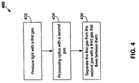
- a further embodiment of the present invention provides a method including (a) producing light with a first gas, (b) processing optics with a second gas, and (c) separating the first gas from the second gas with a third gas that flows between them.
- the first and third gas are pumped from the first chamber, the first gas is separated from the third gas, such that the first gas can be recycled for reuse.
- FIG. 1 show a system 100 for forming a pattern on a wafer or substrate 102 according to embodiments of the present invention.
- a light source 104 e.g., an EUV light source
- the light beam After reflecting from reticle or mask 110, the light beam passes through projection optics 112, which is used to transfer a pattern from a surface 114 of reticle or mask 110 onto a surface 116 of wafer or substrate 102.
- projection optics 112 is used to transfer a pattern from a surface 114 of reticle or mask 110 onto a surface 116 of wafer or substrate 102.
- Other arrangements of these elements can be used without departing from the spirit and scope of the present invention.
- FIG. 2 shows details of an exemplary system 200 according to an embodiment of the present invention.
- System 200 includes a first chamber (e.g., a light source chamber or vacuum light source chamber) 202 and second chamber (e.g., an optics chamber or optics vacuum chamber) 204.
- Second chamber 204 can include one or more of: a beam conditioner, illumination optics, a reticle, projection optics, and/or a wafer.
- First chamber 202 and second chamber 204 can be coupled via a gaslock 206.
- a first gas or other material 208 e.g., xenon, lithium vapor, tin, krypton, water vapor, a metal target, or the like
- First gas 208 is only supplied to first chamber 202 during a time when light is being generated. At other times (e.g., during stand-by, idle, maintenance, or other modes), first chamber 202 is substantially in a vacuum state.
- Second chamber 204 includes a second gas (e.g., a process gases, such as helium, argon, hydrogen, nitrogen, or the like) 210.
- FIG. 3 illustrates an interaction of gases in gas lock 206 according to embodiments of the present invention.
- First and second gases 208 and 210 are supplied to first and second chambers 202 and 204 via first and second gas sources 300 and 302.
- a third gas 304 e.g., helium, neon, nitrogen, etc.
- third gas 304 can be continuously passed through an inlet in gas lock 206.
- Third gas 304 should be chosen so that it is easily stripped out of first gas 208 during a recycling device stage (e.g., a purifying and recycling stage), as discussed below.
- a recycling device stage e.g., a purifying and recycling stage
- third gas 304 can be chosen to have a freezing point (e.g., - 60°C), which is substantially above a freezing point (e.g., -200° C) of first gas 208. Then, third gas 304 is frozen, separated from first gas 208, and removed from recycling device 314. In various embodiments, first gas 208 can either be reused directly from recycling device 314 or transmitted to gas source 300.
- a freezing point e.g., - 60°C
- a freezing point e.g., -200° C
- first gas 208 can either be reused directly from recycling device 314 or transmitted to gas source 300.
- third gas 304 can be reused after exiting recycling device 314 or it can be discarded. It is also to be appreciated that although pump 312 and recycling device 314 are shown coupled directly to a top of first chamber 202, either one or both of pump 312 and recycling device 314 can be indirectly coupled to first chamber 202 and/or they can be positioned anywhere with respect to first chamber 202. Also, although not shown, it is to be appreciated that second gas 210 can also be recycled using similar or functionally similar devices, as is known in the art.
Landscapes
- Health & Medical Sciences (AREA)
- Epidemiology (AREA)
- Public Health (AREA)
- Life Sciences & Earth Sciences (AREA)
- Atmospheric Sciences (AREA)
- General Physics & Mathematics (AREA)
- Environmental & Geological Engineering (AREA)
- Engineering & Computer Science (AREA)
- Physics & Mathematics (AREA)
- Toxicology (AREA)
- Exposure Of Semiconductors, Excluding Electron Or Ion Beam Exposure (AREA)
- Exposure And Positioning Against Photoresist Photosensitive Materials (AREA)
- Electron Beam Exposure (AREA)
Abstract
Description
Claims (26)
- A system comprising:a first chamber including an element that emits light based on a first gas;a second chamber that uses the emitted light to perform a process and that includes a second gas;a gas lock that couples the first chamber to the second chamber; anda gas source that supplies a third gas between the first and the second gas in the gaslock, such that the first gas is isolated from the second gas in the gaslock.
- The system of claim 1, wherein said first gas is selected from the group consisting of xenon, lithium vapor, tin, krypton, and water vapor.
- The system of claim 1, wherein said second gas is selected from the group consisting of helium, argon, hydrogen, and nitrogen.
- The system of claim 1, wherein said third gas is selected from the group consisting of helium, neon, and nitrogen.
- The system of claim 1, further comprising:a pump that pumps the first and third gas from the first chamber; anda recycling device that separates the first gas from the third gas, such that the first gas is reused to form the emitted light.
- The system of claim 5, wherein the pump and the recycling device are positioned outside the first chamber.
- The system of claim 1, wherein the element emits extreme ultra violet light.
- The system of claim 1, wherein the first chamber houses a plasma light source.
- The system of claim 8, wherein the plasma light source produces extreme ultra violet light.
- A system, comprising:a light source chamber having a first gas;an optics chamber having a second gas;a first means for coupling said light source chamber to said optics chamber; anda second means for passing a third gas through said first means to isolate said first gas from said second gas.
- The system of claim 10, wherein said first gas is selected from the group consisting of xenon, lithium vapor, tin, krypton, and water vapor.
- The system of claim 10, wherein said second gas is selected from the group consisting of helium, argon, hydrogen, and nitrogen.
- The system of claim 10, wherein said third gas is selected from the group consisting of helium, neon, and nitrogen.
- The system of claim 10, further comprising:a pump that pumps the first and third gas from the first chamber; anda recycling device that separates the first gas from the third gas, such that the first gas is reused to form the emitted light.
- The system of claim 14, wherein the pump and the recycling device are positioned outside the first chamber.
- The system of claim 10, wherein the first chamber emits extreme ultra violet light.
- The system of claim 10, wherein the first chamber houses a plasma light source.
- The system of claim 17, wherein the plasma light source produces extreme ultra violet light.
- A method comprising:(a) producing light with a first gas;(b) processing optics with a second gas; and(c) separating the first gas from the second gas with a third gas that flows between them.
- The method of claim 19 comprising, wherein said first gas is selected from the group consisting of xenon, lithium vapor, tin, krypton, and water vapor.
- The method of claim 19, wherein said second gas is selected from the group consisting of helium, argon, hydrogen, and nitrogen.
- The method of claim 19, wherein said third gas is selected from the group consisting of helium, neon, and nitrogen.
- The method of claim 19, further comprising separating the first gas from the third gas and recycling the first gas.
- The method of claim 19, wherein said producing step (a) produces extreme ultra violet light.
- The method of claim 19, wherein said processing step (b) reduces contamination in an optics chamber.
- The method of claim 19, wherein said processing step (b) protects optics in an optics chamber.
Applications Claiming Priority (2)
| Application Number | Priority Date | Filing Date | Title |
|---|---|---|---|
| US300898 | 2002-11-21 | ||
| US10/300,898 US6770895B2 (en) | 2002-11-21 | 2002-11-21 | Method and apparatus for isolating light source gas from main chamber gas in a lithography tool |
Publications (2)
| Publication Number | Publication Date |
|---|---|
| EP1422568A2 true EP1422568A2 (en) | 2004-05-26 |
| EP1422568A3 EP1422568A3 (en) | 2006-02-01 |
Family
ID=32229878
Family Applications (1)
| Application Number | Title | Priority Date | Filing Date |
|---|---|---|---|
| EP03026062A Ceased EP1422568A3 (en) | 2002-11-21 | 2003-11-12 | Method and apparatus for preventing the mixing of a light source gas with the main chamber gas in a lithography tool |
Country Status (7)
| Country | Link |
|---|---|
| US (3) | US6770895B2 (en) |
| EP (1) | EP1422568A3 (en) |
| JP (1) | JP4516738B2 (en) |
| KR (1) | KR100822071B1 (en) |
| CN (1) | CN100476584C (en) |
| SG (1) | SG106161A1 (en) |
| TW (1) | TWI331702B (en) |
Cited By (5)
| Publication number | Priority date | Publication date | Assignee | Title |
|---|---|---|---|---|
| EP1460479A3 (en) * | 2003-03-20 | 2006-02-01 | ASML Holding N.V. | Method and apparatus for recycling gases in a lithography tool |
| EP1664544A1 (en) * | 2003-09-24 | 2006-06-07 | The BOC Group plc | Vacuum pumping system |
| US7087911B2 (en) | 2002-11-21 | 2006-08-08 | Asml Holding N.V. | Method for recycling gases used in a lithography tool |
| US7361911B2 (en) | 2004-12-09 | 2008-04-22 | Asml Netherlands B.V. | Lithographic apparatus and device manufacturing method |
| EP2098909A1 (en) * | 2008-03-04 | 2009-09-09 | Ushio Denki Kabushiki Kaisha | Connection device |
Families Citing this family (21)
| Publication number | Priority date | Publication date | Assignee | Title |
|---|---|---|---|---|
| US8094288B2 (en) * | 2004-05-11 | 2012-01-10 | Asml Netherlands B.V. | Lithographic apparatus and device manufacturing method |
| US9077022B2 (en) * | 2004-10-29 | 2015-07-07 | Medtronic, Inc. | Lithium-ion battery |
| US7868304B2 (en) * | 2005-02-07 | 2011-01-11 | Asml Netherlands B.V. | Method for removal of deposition on an optical element, lithographic apparatus, device manufacturing method, and device manufactured thereby |
| US7279690B2 (en) * | 2005-03-31 | 2007-10-09 | Asml Netherlands B.V. | Lithographic apparatus and device manufacturing method |
| DE102006054726B4 (en) * | 2006-11-21 | 2014-09-11 | Asml Netherlands B.V. | Method for removing contaminations on optical surfaces and optical arrangement |
| JP2009036182A (en) * | 2007-08-03 | 2009-02-19 | Fuji Koki Corp | Control valve for variable capacity compressor |
| TWI402628B (en) * | 2007-08-31 | 2013-07-21 | Cymer Inc | System managing gas flow between chambers of an extreme ultraviolet (euv) photolithography apparatus |
| US8115900B2 (en) * | 2007-09-17 | 2012-02-14 | Asml Netherlands B.V. | Lithographic apparatus and device manufacturing method |
| WO2009142549A2 (en) | 2008-05-22 | 2009-11-26 | Vladimir Yegorovich Balakin | Multi-axis charged particle cancer therapy method and apparatus |
| US8569717B2 (en) | 2008-05-22 | 2013-10-29 | Vladimir Balakin | Intensity modulated three-dimensional radiation scanning method and apparatus |
| US8637833B2 (en) | 2008-05-22 | 2014-01-28 | Vladimir Balakin | Synchrotron power supply apparatus and method of use thereof |
| US8288742B2 (en) | 2008-05-22 | 2012-10-16 | Vladimir Balakin | Charged particle cancer therapy patient positioning method and apparatus |
| WO2009142547A2 (en) | 2008-05-22 | 2009-11-26 | Vladimir Yegorovich Balakin | Charged particle beam acceleration method and apparatus as part of a charged particle cancer therapy system |
| US8368038B2 (en) | 2008-05-22 | 2013-02-05 | Vladimir Balakin | Method and apparatus for intensity control of a charged particle beam extracted from a synchrotron |
| US8373145B2 (en) * | 2008-05-22 | 2013-02-12 | Vladimir Balakin | Charged particle cancer therapy system magnet control method and apparatus |
| US8188688B2 (en) | 2008-05-22 | 2012-05-29 | Vladimir Balakin | Magnetic field control method and apparatus used in conjunction with a charged particle cancer therapy system |
| US8129699B2 (en) | 2008-05-22 | 2012-03-06 | Vladimir Balakin | Multi-field charged particle cancer therapy method and apparatus coordinated with patient respiration |
| US8229072B2 (en) * | 2008-07-14 | 2012-07-24 | Vladimir Balakin | Elongated lifetime X-ray method and apparatus used in conjunction with a charged particle cancer therapy system |
| CN104597115B (en) * | 2015-02-12 | 2019-03-19 | 中国科学院光电研究院 | Vacuum obtaining device and corresponding testing method of extreme ultraviolet radiation material testing system |
| WO2018039363A1 (en) | 2016-08-23 | 2018-03-01 | Randall May International, Inc. | Instrument carrier with auto-release articulating back brace |
| CN111065887A (en) * | 2017-09-12 | 2020-04-24 | Asml控股股份有限公司 | Beam pointing monitoring and compensation system |
Family Cites Families (55)
| Publication number | Priority date | Publication date | Assignee | Title |
|---|---|---|---|---|
| JPS58225636A (en) * | 1982-06-25 | 1983-12-27 | バッテル・ディベロプメント・コーポレーション | Device for emitting x-ray to object |
| US4692934A (en) * | 1984-11-08 | 1987-09-08 | Hampshire Instruments | X-ray lithography system |
| JPH0744020B2 (en) * | 1986-05-13 | 1995-05-15 | 日本電信電話株式会社 | X-ray extractor for plasma X-ray source |
| GB2195070B (en) * | 1986-09-11 | 1991-04-03 | Hoya Corp | Laser plasma x-ray generator capable of continuously generating x-rays |
| JPS63292553A (en) * | 1987-05-25 | 1988-11-29 | Agency Of Ind Science & Technol | Plasma scattering prevention mechanism in X-ray generator |
| JP2572787B2 (en) * | 1987-11-18 | 1997-01-16 | 株式会社日立製作所 | X-ray generator |
| US5103102A (en) * | 1989-02-24 | 1992-04-07 | Micrion Corporation | Localized vacuum apparatus and method |
| EP0676672B1 (en) | 1994-04-08 | 2003-06-11 | Canon Kabushiki Kaisha | Processing method and apparatus for a resist-coated substrate |
| US6341006B1 (en) * | 1995-04-07 | 2002-01-22 | Nikon Corporation | Projection exposure apparatus |
| EP0826629B1 (en) * | 1996-08-27 | 2002-11-20 | The Boc Group, Inc. | Recovery of noble gases |
| US6133577A (en) * | 1997-02-04 | 2000-10-17 | Advanced Energy Systems, Inc. | Method and apparatus for producing extreme ultra-violet light for use in photolithography |
| JPH10221499A (en) * | 1997-02-07 | 1998-08-21 | Hitachi Ltd | Laser plasma X-ray source, semiconductor exposure apparatus and semiconductor exposure method using the same |
| US6031241A (en) * | 1997-03-11 | 2000-02-29 | University Of Central Florida | Capillary discharge extreme ultraviolet lamp source for EUV microlithography and other related applications |
| US6586757B2 (en) * | 1997-05-12 | 2003-07-01 | Cymer, Inc. | Plasma focus light source with active and buffer gas control |
| US5763930A (en) * | 1997-05-12 | 1998-06-09 | Cymer, Inc. | Plasma focus high energy photon source |
| US6566667B1 (en) * | 1997-05-12 | 2003-05-20 | Cymer, Inc. | Plasma focus light source with improved pulse power system |
| US6064072A (en) * | 1997-05-12 | 2000-05-16 | Cymer, Inc. | Plasma focus high energy photon source |
| US6376329B1 (en) * | 1997-08-04 | 2002-04-23 | Nikon Corporation | Semiconductor wafer alignment using backside illumination |
| JPH11204411A (en) | 1998-01-19 | 1999-07-30 | Nikon Corp | Coating development exposure equipment |
| WO1999063790A1 (en) | 1998-05-29 | 1999-12-09 | Nikon Corporation | Laser-excited plasma light source, exposure apparatus and its manufacturing method, and device manufacturing method |
| US6385290B1 (en) * | 1998-09-14 | 2002-05-07 | Nikon Corporation | X-ray apparatus |
| WO2000019496A1 (en) * | 1998-09-28 | 2000-04-06 | Hitachi, Ltd. | Laser plasma x-ray generator, semiconductor aligner having the generator, and semiconductor exposure method |
| JP3317957B2 (en) * | 1999-03-15 | 2002-08-26 | サイマー インコーポレイテッド | Plasma focus high energy photon source with blast shield |
| US6190835B1 (en) * | 1999-05-06 | 2001-02-20 | Advanced Energy Systems, Inc. | System and method for providing a lithographic light source for a semiconductor manufacturing process |
| JP2001108799A (en) * | 1999-10-08 | 2001-04-20 | Nikon Corp | X-ray generator, X-ray exposure apparatus, and method for manufacturing semiconductor device |
| EP1098225A3 (en) | 1999-11-05 | 2002-04-10 | Asm Lithography B.V. | Lithographic projection apparatus with purge gas system and method using the same |
| JP2003515731A (en) * | 1999-12-06 | 2003-05-07 | グラクソ グループ リミテッド | Systems and methods for performing higher order combinatorial chemical processes |
| TWI246872B (en) * | 1999-12-17 | 2006-01-01 | Asml Netherlands Bv | Radiation source for use in lithographic projection apparatus |
| US6469310B1 (en) * | 1999-12-17 | 2002-10-22 | Asml Netherlands B.V. | Radiation source for extreme ultraviolet radiation, e.g. for use in lithographic projection apparatus |
| TW508980B (en) * | 1999-12-23 | 2002-11-01 | Koninkl Philips Electronics Nv | Method of generating extremely short-wave radiation, method of manufacturing a device by means of said radiation, extremely short-wave radiation source unit and lithographic projection apparatus provided with such a radiation source unit |
| TW502559B (en) * | 1999-12-24 | 2002-09-11 | Koninkl Philips Electronics Nv | Method of generating extremely short-wave radiation, method of manufacturing a device by means of said radiation, extremely short-wave radiation source unit and lithographic projection apparatus provided with such a radiation source unit |
| JP2001345263A (en) * | 2000-03-31 | 2001-12-14 | Nikon Corp | Aligner, exposure method, and device-manufacturing method |
| US6559922B2 (en) * | 2000-05-03 | 2003-05-06 | Eric C. Hansell | Method and apparatus for a non-contact scavenging seal |
| US6667484B2 (en) * | 2000-07-03 | 2003-12-23 | Asml Netherlands B.V. | Radiation source, lithographic apparatus, device manufacturing method, and device manufactured thereby |
| EP1186958B1 (en) | 2000-09-04 | 2007-03-14 | ASML Netherlands B.V. | Lithographic projection apparatus |
| DE10061248B4 (en) * | 2000-12-09 | 2004-02-26 | Carl Zeiss | Method and device for in-situ decontamination of an EUV lithography device |
| US6576912B2 (en) * | 2001-01-03 | 2003-06-10 | Hugo M. Visser | Lithographic projection apparatus equipped with extreme ultraviolet window serving simultaneously as vacuum window |
| US6614505B2 (en) * | 2001-01-10 | 2003-09-02 | Asml Netherlands B.V. | Lithographic projection apparatus, device manufacturing method, and device manufactured thereby |
| WO2002056332A1 (en) * | 2001-01-10 | 2002-07-18 | Ebara Corporation | Inspection apparatus and inspection method with electron beam, and device manufacturing method comprising the inspection apparatus |
| JP2002289585A (en) | 2001-03-26 | 2002-10-04 | Ebara Corp | Neutral beam processing equipment |
| DE10139677A1 (en) | 2001-04-06 | 2002-10-17 | Fraunhofer Ges Forschung | Method and device for generating extremely ultraviolet radiation and soft X-rays |
| DE10134033A1 (en) | 2001-04-06 | 2002-10-17 | Fraunhofer Ges Forschung | Method and device for generating extreme ultraviolet radiation / soft X-rays |
| KR20030076238A (en) | 2001-04-17 | 2003-09-26 | 코닌클리즈케 필립스 일렉트로닉스 엔.브이. | Euv-transparent interface structure |
| JP4995379B2 (en) * | 2001-06-18 | 2012-08-08 | ギガフォトン株式会社 | Light source device and exposure apparatus using the same |
| JP2003068630A (en) * | 2001-08-29 | 2003-03-07 | Kyocera Corp | Exposure equipment |
| WO2003034153A2 (en) * | 2001-10-12 | 2003-04-24 | Koninklijke Philips Electronics N.V. | Lithographic apparatus and device manufacturing method |
| US6762424B2 (en) * | 2002-07-23 | 2004-07-13 | Intel Corporation | Plasma generation |
| DE10238096B3 (en) | 2002-08-21 | 2004-02-19 | Fraunhofer-Gesellschaft zur Förderung der angewandten Forschung e.V. | Gas discharge lamp for extreme UV lithography or X-ray microscopy has tapered electrode opening for transport of charge carriers from external region to discharge space |
| US7002168B2 (en) * | 2002-10-15 | 2006-02-21 | Cymer, Inc. | Dense plasma focus radiation source |
| JP2004170787A (en) * | 2002-11-21 | 2004-06-17 | Toshiba Corp | Display device and driving method thereof |
| US6770895B2 (en) | 2002-11-21 | 2004-08-03 | Asml Holding N.V. | Method and apparatus for isolating light source gas from main chamber gas in a lithography tool |
| DE10256663B3 (en) | 2002-12-04 | 2005-10-13 | Fraunhofer-Gesellschaft zur Förderung der angewandten Forschung e.V. | Gas discharge lamp for EUV radiation |
| DE10310623B8 (en) | 2003-03-10 | 2005-12-01 | Fraunhofer-Gesellschaft zur Förderung der angewandten Forschung e.V. | Method and apparatus for generating a plasma by electrical discharge in a discharge space |
| EP1606980B1 (en) | 2003-03-18 | 2010-08-04 | Philips Intellectual Property & Standards GmbH | Device for and method of generating extreme ultraviolet and/or soft x-ray radiation by means of a plasma |
| US6919573B2 (en) * | 2003-03-20 | 2005-07-19 | Asml Holding N.V | Method and apparatus for recycling gases used in a lithography tool |
-
2002
- 2002-11-21 US US10/300,898 patent/US6770895B2/en not_active Expired - Lifetime
-
2003
- 2003-11-12 EP EP03026062A patent/EP1422568A3/en not_active Ceased
- 2003-11-13 SG SG200306781A patent/SG106161A1/en unknown
- 2003-11-17 TW TW092132161A patent/TWI331702B/en not_active IP Right Cessation
- 2003-11-20 KR KR1020030082500A patent/KR100822071B1/en not_active Expired - Fee Related
- 2003-11-21 CN CNB2003101183374A patent/CN100476584C/en not_active Expired - Fee Related
- 2003-11-21 JP JP2003392310A patent/JP4516738B2/en not_active Expired - Fee Related
-
2004
- 2004-02-04 US US10/770,476 patent/US6894293B2/en not_active Expired - Lifetime
-
2005
- 2005-03-24 US US11/087,639 patent/US7087911B2/en not_active Expired - Fee Related
Cited By (7)
| Publication number | Priority date | Publication date | Assignee | Title |
|---|---|---|---|---|
| US7087911B2 (en) | 2002-11-21 | 2006-08-08 | Asml Holding N.V. | Method for recycling gases used in a lithography tool |
| EP1460479A3 (en) * | 2003-03-20 | 2006-02-01 | ASML Holding N.V. | Method and apparatus for recycling gases in a lithography tool |
| US7135693B2 (en) | 2003-03-20 | 2006-11-14 | Asml Holding N.V. | Method and apparatus for recycling gases used in a lithography tool |
| EP1664544A1 (en) * | 2003-09-24 | 2006-06-07 | The BOC Group plc | Vacuum pumping system |
| US7361911B2 (en) | 2004-12-09 | 2008-04-22 | Asml Netherlands B.V. | Lithographic apparatus and device manufacturing method |
| EP2098909A1 (en) * | 2008-03-04 | 2009-09-09 | Ushio Denki Kabushiki Kaisha | Connection device |
| US8039820B2 (en) | 2008-03-04 | 2011-10-18 | Ushio Denki Kabushiki Kaisha | Connection device |
Also Published As
| Publication number | Publication date |
|---|---|
| JP2004172626A (en) | 2004-06-17 |
| KR100822071B1 (en) | 2008-04-15 |
| TW200411341A (en) | 2004-07-01 |
| KR20040045327A (en) | 2004-06-01 |
| US20050169767A1 (en) | 2005-08-04 |
| US20040099816A1 (en) | 2004-05-27 |
| US6770895B2 (en) | 2004-08-03 |
| EP1422568A3 (en) | 2006-02-01 |
| SG106161A1 (en) | 2004-09-30 |
| CN1503058A (en) | 2004-06-09 |
| TWI331702B (en) | 2010-10-11 |
| US7087911B2 (en) | 2006-08-08 |
| CN100476584C (en) | 2009-04-08 |
| JP4516738B2 (en) | 2010-08-04 |
| US6894293B2 (en) | 2005-05-17 |
| US20040155205A1 (en) | 2004-08-12 |
Similar Documents
| Publication | Publication Date | Title |
|---|---|---|
| US6770895B2 (en) | Method and apparatus for isolating light source gas from main chamber gas in a lithography tool | |
| US7135693B2 (en) | Method and apparatus for recycling gases used in a lithography tool | |
| US9000404B2 (en) | Systems and methods for optics cleaning in an EUV light source | |
| KR100750412B1 (en) | EV radiation generating method, EV radiation manufacturing method, EV radiation source unit, lithographic projection apparatus | |
| KR100659698B1 (en) | Method for Cleaning Microlithography-Projected Exposure Apparatus | |
| US10067418B2 (en) | Particle removal system and method thereof | |
| US7872729B2 (en) | Filter system for light source | |
| TW200903181A (en) | Exposure apparatus | |
| CN112823314B (en) | Non-photoresist lithography, phototool and method using VUV or deep UV lamps | |
| US20080088810A1 (en) | EUV exposure apparatus for in-situ exposing of substrate and cleaning of optical element included apparatus and method of cleaning optical element included in apparatus | |
| US20210185793A1 (en) | Adhesive material removal from photomask in ultraviolet lithography application | |
| EP2959263B1 (en) | Methods and apparatus for cleaning objects in a chamber of an optical instrument by generating reactive ions using photon radiation | |
| JP2008522399A (en) | Protection of surfaces exposed to charged particles | |
| JP6844798B1 (en) | Optical equipment and methods for preventing contamination of optical equipment | |
| US6418187B1 (en) | X-ray mask structure, and X-ray exposure method and apparatus using the same | |
| US20130160793A1 (en) | Plasma generating apparatus and process for simultaneous exposure of a workpiece to electromagnetic radiation and plasma |
Legal Events
| Date | Code | Title | Description |
|---|---|---|---|
| PUAI | Public reference made under article 153(3) epc to a published international application that has entered the european phase |
Free format text: ORIGINAL CODE: 0009012 |
|
| AK | Designated contracting states |
Kind code of ref document: A2 Designated state(s): AT BE BG CH CY CZ DE DK EE ES FI FR GB GR HU IE IT LI LU MC NL PT RO SE SI SK TR |
|
| AX | Request for extension of the european patent |
Extension state: AL LT LV MK |
|
| RAP1 | Party data changed (applicant data changed or rights of an application transferred) |
Owner name: ASML HOLDING N.V. |
|
| RTI1 | Title (correction) |
Free format text: METHOD AND APPARATUS FOR PREVENTING THE MIXING OF A LIGHT SOURCE GAS WITH THE MAIN CHAMBER GAS IN A LITHOGRAPHY TOOL |
|
| PUAL | Search report despatched |
Free format text: ORIGINAL CODE: 0009013 |
|
| AK | Designated contracting states |
Kind code of ref document: A3 Designated state(s): AT BE BG CH CY CZ DE DK EE ES FI FR GB GR HU IE IT LI LU MC NL PT RO SE SI SK TR |
|
| AX | Request for extension of the european patent |
Extension state: AL LT LV MK |
|
| 17P | Request for examination filed |
Effective date: 20060724 |
|
| AKX | Designation fees paid |
Designated state(s): DE FR GB IT NL |
|
| 17Q | First examination report despatched |
Effective date: 20060929 |
|
| STAA | Information on the status of an ep patent application or granted ep patent |
Free format text: STATUS: THE APPLICATION HAS BEEN REFUSED |
|
| 18R | Application refused |
Effective date: 20081112 |