EP1422465A1 - Method of fitting a cable into a pipe - Google Patents
Method of fitting a cable into a pipe Download PDFInfo
- Publication number
- EP1422465A1 EP1422465A1 EP20020360322 EP02360322A EP1422465A1 EP 1422465 A1 EP1422465 A1 EP 1422465A1 EP 20020360322 EP20020360322 EP 20020360322 EP 02360322 A EP02360322 A EP 02360322A EP 1422465 A1 EP1422465 A1 EP 1422465A1
- Authority
- EP
- European Patent Office
- Prior art keywords
- cable
- pipe
- fitting
- fusion
- saddle fitting
- Prior art date
- Legal status (The legal status is an assumption and is not a legal conclusion. Google has not performed a legal analysis and makes no representation as to the accuracy of the status listed.)
- Granted
Links
- 238000000034 method Methods 0.000 title claims abstract description 32
- 239000004033 plastic Substances 0.000 claims abstract description 24
- 229920003023 plastic Polymers 0.000 claims abstract description 24
- 239000012530 fluid Substances 0.000 claims abstract description 13
- 238000005553 drilling Methods 0.000 claims description 37
- 238000007789 sealing Methods 0.000 claims description 12
- 238000009434 installation Methods 0.000 abstract description 12
- 230000004927 fusion Effects 0.000 description 21
- 238000005286 illumination Methods 0.000 description 4
- 239000000835 fiber Substances 0.000 description 3
- 238000010438 heat treatment Methods 0.000 description 3
- 239000000463 material Substances 0.000 description 3
- 238000009412 basement excavation Methods 0.000 description 2
- 230000000694 effects Effects 0.000 description 2
- 238000007499 fusion processing Methods 0.000 description 2
- 229920001903 high density polyethylene Polymers 0.000 description 2
- 239000004700 high-density polyethylene Substances 0.000 description 2
- 238000003384 imaging method Methods 0.000 description 2
- 239000013307 optical fiber Substances 0.000 description 2
- 238000004804 winding Methods 0.000 description 2
- 238000011109 contamination Methods 0.000 description 1
- 239000003651 drinking water Substances 0.000 description 1
- 235000020188 drinking water Nutrition 0.000 description 1
- 239000007789 gas Substances 0.000 description 1
- 239000010865 sewage Substances 0.000 description 1
- 238000013022 venting Methods 0.000 description 1
Images
Classifications
-
- G—PHYSICS
- G02—OPTICS
- G02B—OPTICAL ELEMENTS, SYSTEMS OR APPARATUS
- G02B6/00—Light guides; Structural details of arrangements comprising light guides and other optical elements, e.g. couplings
- G02B6/46—Processes or apparatus adapted for installing or repairing optical fibres or optical cables
- G02B6/50—Underground or underwater installation; Installation through tubing, conduits or ducts
-
- Y—GENERAL TAGGING OF NEW TECHNOLOGICAL DEVELOPMENTS; GENERAL TAGGING OF CROSS-SECTIONAL TECHNOLOGIES SPANNING OVER SEVERAL SECTIONS OF THE IPC; TECHNICAL SUBJECTS COVERED BY FORMER USPC CROSS-REFERENCE ART COLLECTIONS [XRACs] AND DIGESTS
- Y10—TECHNICAL SUBJECTS COVERED BY FORMER USPC
- Y10T—TECHNICAL SUBJECTS COVERED BY FORMER US CLASSIFICATION
- Y10T137/00—Fluid handling
- Y10T137/0318—Processes
- Y10T137/0402—Cleaning, repairing, or assembling
- Y10T137/0441—Repairing, securing, replacing, or servicing pipe joint, valve, or tank
- Y10T137/0458—Tapping pipe, keg, or tank
- Y10T137/0463—Particular aperture forming means
-
- Y—GENERAL TAGGING OF NEW TECHNOLOGICAL DEVELOPMENTS; GENERAL TAGGING OF CROSS-SECTIONAL TECHNOLOGIES SPANNING OVER SEVERAL SECTIONS OF THE IPC; TECHNICAL SUBJECTS COVERED BY FORMER USPC CROSS-REFERENCE ART COLLECTIONS [XRACs] AND DIGESTS
- Y10—TECHNICAL SUBJECTS COVERED BY FORMER USPC
- Y10T—TECHNICAL SUBJECTS COVERED BY FORMER US CLASSIFICATION
- Y10T137/00—Fluid handling
- Y10T137/0318—Processes
- Y10T137/0402—Cleaning, repairing, or assembling
- Y10T137/0441—Repairing, securing, replacing, or servicing pipe joint, valve, or tank
- Y10T137/0458—Tapping pipe, keg, or tank
- Y10T137/0463—Particular aperture forming means
- Y10T137/0469—Cutter or cutting tool
-
- Y—GENERAL TAGGING OF NEW TECHNOLOGICAL DEVELOPMENTS; GENERAL TAGGING OF CROSS-SECTIONAL TECHNOLOGIES SPANNING OVER SEVERAL SECTIONS OF THE IPC; TECHNICAL SUBJECTS COVERED BY FORMER USPC CROSS-REFERENCE ART COLLECTIONS [XRACs] AND DIGESTS
- Y10—TECHNICAL SUBJECTS COVERED BY FORMER USPC
- Y10T—TECHNICAL SUBJECTS COVERED BY FORMER US CLASSIFICATION
- Y10T137/00—Fluid handling
- Y10T137/598—With repair, tapping, assembly, or disassembly means
- Y10T137/612—Tapping a pipe, keg, or apertured tank under pressure
-
- Y—GENERAL TAGGING OF NEW TECHNOLOGICAL DEVELOPMENTS; GENERAL TAGGING OF CROSS-SECTIONAL TECHNOLOGIES SPANNING OVER SEVERAL SECTIONS OF THE IPC; TECHNICAL SUBJECTS COVERED BY FORMER USPC CROSS-REFERENCE ART COLLECTIONS [XRACs] AND DIGESTS
- Y10—TECHNICAL SUBJECTS COVERED BY FORMER USPC
- Y10T—TECHNICAL SUBJECTS COVERED BY FORMER US CLASSIFICATION
- Y10T137/00—Fluid handling
- Y10T137/598—With repair, tapping, assembly, or disassembly means
- Y10T137/612—Tapping a pipe, keg, or apertured tank under pressure
- Y10T137/6123—With aperture forming means
Definitions
- the invention relates to a method of installing a cable or conduit into at least one plastic pipe of a pipeline system carrying a fluid.
- a translating member is introduced into the pressurized gas pipe via an entry port in a first drilling fitting attached to the pressurized gas pipeline.
- Tools are deployed within a first pressure lock housing attached to the first drilling fitting by using a first manipulator located in the first air housing.
- the duct rod is advanced within the pressurized gas pipeline by a driving mechanism, until a second drilling fitting is reached.
- the translating member is attached to a fiber optic conduit or cable.
- the duct rod and fiber optic conduit are then pulled back through the pressurized gas pipeline by the driving mechanism.
- a conduit or cable is installed in a gas service line, to provide an optical fiber between an optical fiber trunk line or ring and building.
- This object is achieved by attaching a first saddle fitting at a first location on a plastic pipe by electro-fusion, opening the pipe at the first location, introducing a pull body or a cable through the lock system and the saddle fitting into the pipe towards a second location or retrieving at least part of a pull body or of a cable introduced at a second location, pulling the cable by means of the pull body or directly through the pipe.
- the inventive method allows installation of cables, in particular for telecommunications, in plastic pipes at low cost and without having to shut off the fluid supply, p.ex. gas supply. Gas-tight sealing between the saddle fitting and the pipe is obtained by electro-fusion. No additional sealing mechanism is needed.
- the shape of the saddle fitting is adapted to the shape and size of the plastic pipe to which it is to be fused.
- at least the surface of the saddle fitting touching the plastic pipe is made of plastic as well.
- both the pipe and the surface of the saddle fitting used for electro-fusion are of the same material.
- the whole saddle fitting is made of plastic material, in particular high density polyethylene (HDPE).
- HDPE high density polyethylene
- the lock system can comprise the saddle fitting as an integrated part.
- a fitting may be installed and the pipe may be opened as well.
- the pull body can, p. ex.
- a cable or conduit can be attached to the free end of the pull body and the cable can be pulled from the second location to the first location and through the opening at the first location.
- the pull body could also be introduced at the second location and be retrieved at the second location, where a cable or conduit could be connected and the cable or conduit could subsequently be pulled to the second location.
- the cable or conduit could be connected to the opposite end of the pull body. The pull body could be transferred from the first to the second location and the cable could be pulled from the first to the second location after the pull body.
- the fitting at the second location could be attached to a pipe branch.
- a saddle fitting is attached by electro-fusion.
- electro-fusion the same components can be used at both locations and a lock system can also easily be installed at the second location.
- a second electro-fusion saddle fitting allows opening the pipe at any point and is not restricted to pipe branches.
- an identical lock system is also used at the second location, which further reduces the number of different parts needed for installing a cable in a plastic pipe.
- the pipe is opened by drilling at the first and/or second location. Drilling is the preferred method for providing an opening in the pipe through which the cable can be fed.
- the vacuum causes dirt generated during drilling to be collected outside the pipe. It prevents dirt falling into the pipe and thus contamination of the material flowing in the pipe.
- the drilling of one or both openings in the pipe comprises opening a lower valve and launching the drilling system from a lock room into the saddle fitting region, drilling a hole into the pipe wall, pulling back the drilling system into the lock room, and closing the lower valve.
- This procedure prevents venting the pipe system and large amounts of fluid carried in the pipe system to escape.
- the drilling system can be kept within the lock room, p. ex. in a lock chamber.
- an upper valve could be provided at the lock room. While the lower valve is closed, the drilling system could be introduced into the lock room. After closing the upper valve, the lower valve could be opened and the drilling be performed.
- the drilling system After retrieving the drilling system into the lock room and closing of the lower valve, the drilling system could be removed after opening the upper valve. A pressure drop in the main pipe system can thus be avoided. Furthermore, a smaller lock room could be used if the drilling system, in addition to other components, is not stored in the lock room.
- the cable is preferably installed by following the same sequence of opening and closing the valves for lowering a pull body, p.ex. a parachute attached to a pulling line, into the pipe.
- the pull body is driven by the gas stream to the second location, where it is collected by a catching device, which is lowered into the pipe at the second location using the same sequence of steps as for lowering the drilling system and the pull body.
- the cable can be retrieved by the catching device.
- the catching device can thus be adapted to either retrieve a parachute, a pulling line, a guiding line or the cable.
- the catching device consists of a flexible tube, which has the same outside diameter as the cable to be introduced into the pipe.
- the catching device having the same outer dimensions as the cable has the advantage that the catching device can be introduced into the already installed electro-fusion saddle fitting and/or lock system.
- the catching device comprises an image guide and an illumination means.
- the illumination means is a cold light source.
- the catching device comprises at its end a tool, in particular a gripping tool, which can be manipulated by a user installing the cable into the pipe by means of a manipulator. Catching of the pull body or cable is facilitated by illuminating the inside of the pipe via the illumination means and imaging via the image guide. The user can thus see where the pull body or cable is located in the pipe and where to grip the cable or pull body with the tool.
- the cable is sealed in one or both fittings, in particular by electro-fusion.
- a fluid-tight connection is obtained between the saddle fitting and the cable.
- the outermost layer of the cable is at least in the sealing region made of plastic.
- the cable is introduced in a fluid-tight manner. If the cable is sealed against the pipe or fitting during installation of the cable, the fluid supply does not have to be turned off during installation. Hence, the service of the pipeline system is not interrupted during installation of the cable.
- an electro-fusion saddle fitting comprising a stem, which comprises a seal, in particular a pneumatic seal and/or an electro-fusion fitting for sealing against a cable fed through the stem.
- a saddle fitting facilitates installation of a cable in pipes without turning off the fluid supply.
- the stem comprises a seal, in particular a pneumatic seal
- the cable is sealed against the saddle fitting during installation of the cable, i.e. while the cable is pulled or pushed through the pipe.
- a pneumatic seal can be inflatable and hence easily adapted to the cable diameter.
- the same pneumatic seal can be used for different cable diameters.
- the stem can comprise an electro-fusion fitting.
- the electro-fusion fitting can be an integral part of the stem or it can be a separate part, which can be pushed over the free end of the stem with one end and which can guide the cable with the other end.
- the electro-fusion fitting can be fused to the cable (integral part) or fused to both, the stem and the cable (separate part) in order to form a fluid-tight connection between the stem and the cable.
- the saddle fitting is connected to a hydraulic feeding system.
- the hydraulic feeding system can be connected to the saddle fitting, in particular to the stem of the saddle fitting directly or to the lock system connected to the saddle fitting.
- the hydraulic feeding system comprises a first and a second seal, in particular a first and second hydraulic seal. Between the seals is provided a hydraulic mechanism.
- For feeding the cable into the pipe system the first seal opens while the second seal seals against the cable and thereby grips the cable.
- the hydraulic mechanism then moves the second seal towards the first seal. Thereby the cable is also moved towards the first seal.
- the first seal seals against the cable and thereby grips the cable and the second seal opens and is moved back along the cable by the hydraulic mechanism.
- the hydraulic feeding system operates in opposite direction.
- the saddle fitting or an intermediate lock system can be connected to a fluid-tight container system.
- the cable to be installed is located in a fluid-tight container.
- the container is connected to the saddle fitting in a fluid-tight manner.
- the cable can be introduced into the pipe system without the fluid supply in the pipe system having to be turned off.
- a lock system for installing a cable or conduit into at least one plastic pipe of a pressurized pipeline system comprising a lock room and an upper valve, in particular a sphere valve, provided at one end of the lock room and a lower valve, in particular a sphere valve, provided at the opposite end of the lock room.
- a sphere or ball valve has the advantage that the inner diameter of the sphere valve, when opened, corresponds to the inner diameter of the tubular part it is attached to.
- the lock room comprises a driller and/or a pull body and/or a parachute.
- the equipment needed for installing a cable i.e. for opening the pipe and for pulling the cable from one location of the pipe to another can be stored and arranged in the lock room.
- Different lock chambers can be provided in the lock room for the different stored parts.
- the pull body can, p. ex. be a guide line or pulling rope.
- a parachute can be connected to the pull body and therefore be an integrated part of the pull body.
- opening of the upper valve is only necessary to supply additional equipment to the lock room. Most operations can be carried out without having to open the upper valve.
- the lock room could also be of such a size that a spool of thread as well as the cable can be stored in the lock room. Thus, additional fittings could be avoided.
- the lower valve is connected to the stem of a fitting, in particular an electro-fusion saddle fitting.
- the saddle fitting can be directly fused to the plastic pipe. This is an easy and effective means of attaching the fitting to the pipe. It also provides a fluid tight connection to the plastic pipe.
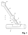
- Fig. 1 shows a perspective view of a lock system 1 for installing a cable in a pressurized plastic pipe 2 , in particular a gas pipe.
- the lock system 1 comprises a lock room 3 having an upper valve 4 , in the embodiment a ball valve, at one end and at the opposite end a lower valve 5 , in the embodiment also a ball valve.
- the lower valve 5 is connected to a seal 6 to be described in more detail later, which is integrated in a stem 7 of a saddle fitting 8 .
- the saddle fitting 8 is realized as a fusion saddle fitting, i.e. the saddle fitting 8 is attached to the outside of the plastic pipe 2 by electro-fusion.
- Incorporated in the stem 7 is an electro-fusion fitting 9 , which can be electro-fused to the installed cable.
- a working well may have to be excavated for obtaining access to the pipe 2. Then the gas pipe 2 may have to be cleaned at the outside. Then the fusion saddle fitting 8 with integrated fusion fitting 9 and seal 6 is installed by fusing the fusion saddle fitting 8 to the plastic pipe 2. After that the lower valve 5 together with the lock space 3 and the upper valve 4 is attached to the saddle fitting 8. This is followed by launching a pneumatic and/or manual drilling system (not shown) at first through the opened upper valve 4 into the lock space 3. After closing the upper valve 4, the lower valve 5 is opened and the drilling system is lowered into the stem 7 through the seal 6. A vacuum is created in the stem 7 and a hole is drilled into the wall of the pipe 2. The vacuum is needed to collect the drilling dirt.
- the drilling system After drilling, the drilling system is pulled back through the seal 6 and the lower valve 5 into the lock space. The lower valve 5 is then closed, so gas cannot escape. Then the upper valve 4 is opened and the drilling system removed. After that a pull body, in particular a guiding line or pulling rope connected to a parachute are launched into the pipe using the same sequence of opening and closing the valves 4, 5 as for the drilling system.
- the parachute is transported in the pipe 2 by the gas flow due to a pressure difference.
- the parachute is caught by a catching device and the parachute and the line attached thereto are moved into the lock space of the second lock system.
- a cable is attached to the pull body and the cable is pulled via the pull body from the second lock system to the first lock system 1.
- the seal 6 and a seal in the second lock system prevent gas escaping while the cable is being pulled from the second lock system to the first.
- the cable is sealed against the stem 7 of the saddle fitting 8 by means of the fusion fitting 9.
- the cable is also sealed against the stem of a saddle fitting at the second lock system. Subsequently, the lock space 3 and the valves 4, 5 can be removed and used for installation of a cable at a different place.
- Fig. 2 shows a perspective view of the saddle fitting 8, which comprises a fusion plate 10 and the stem 7 connected to the fusion plate 10. Electrical connectors 11, 12 are provided, to which electrodes can be connected to effect the fusion process. Lateral flanges 13, 14 and a corresponding back plate 15 are provided for clamping the saddle fitting 8 to the pipe prior to and during fusion to the pipe.
- Fig. 3 shows a cross-section through the stem 7 and integrated fusion fitting 9.
- the fusion fitting 9 comprises electrical connectors 16, 17 to which electrodes can be connected to effect the fusion process.
- the fusion fitting 9 has an annular shape, the inner diameter of which is slightly larger than the outer diameter of the cable 18 .
- the cable 18 can be pushed or pulled through the fusion fitting 9 during installation.
- the inner surface 19 of the fusion fitting 9 is electro-fused to the outer surface 20 of the cable 18.
- the fusion fitting 9 comprises a winding of a wire 21 close to its inner surface 19. After fusion, a gas-tight seal between the cable and the stem 7 is obtained, so gas cannot escape from the pipe.
- Fig. 4 shows a cross-section of an alternative embodiment.
- the fusion fitting 22 is not integrated with the stem 7, but a separate element. With one end 23 , having a larger diameter than the opposite end 24 , the fusion fitting 22 is pushed over the free end 25 of the stem 7.
- the fusion fitting 22 is provided with electrical connectors 26, 27 being in contact with a winding of a resistance heating wire 28 located in the vicinity of the inner surface 29 of the fusion fitting 22.
- the heat necessary for fusion is generated by resistance heating.
- the end 23 of the fusion fitting 22 is fused to the outer surface of the stem 7.
- the opposite end 24 is fused to the outer surface 30 of the cable 31. Consequently, a gas-tight seal between the stem 7 and the cable 31 is obtained.
- Fig. 5 a cross-section through the seal 6 is shown.
- the seal 6 is implemented as a dynamic seal, in particular as a pneumatic seal.
- the seal 6 consists of a sealing ring 32 , which is arranged inside the stem 7.
- the sealing ring 32 has an opening through which the cable 33 is guided.
- the sealing ring 32 is inflatable and can thus be adapted to different diameters of the cable 33.
- a cross section through a hydraulic feeding system 35 is shown.
- the hydraulic feeding system 35 comprises a first and a second hydraulic seal 36 , 37 which can both seal against a cable 38 .
- an expandable sleeve 39 which forms a sealing engagement with seals 36, 37, respectively.
- a hydraulic system 40 Between the first and second seal 36, 37, is further provided a hydraulic system 40 .
- the hydraulic feeding system 35 can be used for either pushing the cable 38 into a pipe system or pulling the cable 38 from a pipe system. For pushing the cable 38 to the left the hydraulic seal 36 is in an open position and the second seal 37 seals against the cable 38 and thereby grips the cable 38.
- first seal 36 seals against cable 38 and thereby grips the cable 38.
- the hydraulic system 40 moves first seal 36 towards the second seal 37, which is in an open position. Due to the movement of the seal 36 the cable 38, which is gripped by seal 36, is moved to the right.
- seal 36 Once the seal 36 is located in the vicinity of the seal 37, the seal 37 closes and seals against the cable 38. Thereby seal 37 holds cable 38 in place.
- the hydraulic system 40 moves the seal 36 back along the cable 38 into its original position with the seal 36 being open. Obviously, the seal 36, 37, which is not moved during the pulling or pushing process, needs to be fixed in space.
- Fig. 7 shows a plan view of a catching device 45 which can be introduced through the stem 7 of a saddle fitting 8.
- the catching device 45 is made of a flexible tube 46 .
- an imaging guide 47 which comprises at its end an illumination means 48 , embodied by a cold light source.
- the image guide 47 exits the flexible tube 46 at point 49 and can be used to visually guide the catching device 45 in the pipe.
- a manipulator 50 which can be used to operate a tool 51 in order to grip a hook 52 connected to a pull body 53 . Once the tool 51 grips hook 52, the pull body 53 can be pulled through the saddle fitting and the stem of the saddle fitting.
- a cable can be attached to hook 52 and the cable can be pulled back through the pipe system via the pull body 53.
- the diameter of the flexible tube corresponds to the diameter of the cable to be installed.
Landscapes
- Physics & Mathematics (AREA)
- General Physics & Mathematics (AREA)
- Optics & Photonics (AREA)
- Pipe Accessories (AREA)
- Laying Of Electric Cables Or Lines Outside (AREA)
- Electric Cable Installation (AREA)
Abstract
Description
- The invention relates to a method of installing a cable or conduit into at least one plastic pipe of a pipeline system carrying a fluid.
- The main cost when installing new cables, in particular telecommunications cables, arises from the necessary excavations to be performed. If in contrast, the cable is installed in already existing pipes, like gas, drinking water, sewage or heating pipes, only local excavations may be necessary. If installation is to be performed in existing pipes, the service of those pipes should ideally not be interrupted.
- In US 2002/0083976 A1 a method of introducing a fiber optic conduit into a pressurized gas pipeline is described. A translating member is introduced into the pressurized gas pipe via an entry port in a first drilling fitting attached to the pressurized gas pipeline. Tools are deployed within a first pressure lock housing attached to the first drilling fitting by using a first manipulator located in the first air housing. The duct rod is advanced within the pressurized gas pipeline by a driving mechanism, until a second drilling fitting is reached. The translating member is attached to a fiber optic conduit or cable. The duct rod and fiber optic conduit are then pulled back through the pressurized gas pipeline by the driving mechanism. A conduit or cable is installed in a gas service line, to provide an optical fiber between an optical fiber trunk line or ring and building.
- It is the object of the invention to provide a method and lock system which allows installation of a cable in a pressurized plastic pipe.
- This object is achieved by attaching a first saddle fitting at a first location on a plastic pipe by electro-fusion, opening the pipe at the first location, introducing a pull body or a cable through the lock system and the saddle fitting into the pipe towards a second location or retrieving at least part of a pull body or of a cable introduced at a second location, pulling the cable by means of the pull body or directly through the pipe. The inventive method allows installation of cables, in particular for telecommunications, in plastic pipes at low cost and without having to shut off the fluid supply, p.ex. gas supply. Gas-tight sealing between the saddle fitting and the pipe is obtained by electro-fusion. No additional sealing mechanism is needed. Preferably, the shape of the saddle fitting is adapted to the shape and size of the plastic pipe to which it is to be fused. For electro-fusion to take place, at least the surface of the saddle fitting touching the plastic pipe is made of plastic as well. Preferably, both the pipe and the surface of the saddle fitting used for electro-fusion are of the same material. It is particularly advantageous, if the whole saddle fitting is made of plastic material, in particular high density polyethylene (HDPE). Within the scope of the invention also falls attaching a lock system to the saddle fitting either before or after electro-fusing the saddle fitting to the pipe. Furthermore, the lock system can comprise the saddle fitting as an integrated part. At the second location a fitting may be installed and the pipe may be opened as well. The pull body can, p. ex. be introduced via the lock system and the first saddle fitting into the pipe at the first location and retrieved at the second location. There, a cable or conduit can be attached to the free end of the pull body and the cable can be pulled from the second location to the first location and through the opening at the first location. Obviously, the pull body could also be introduced at the second location and be retrieved at the second location, where a cable or conduit could be connected and the cable or conduit could subsequently be pulled to the second location. Alternatively, the cable or conduit could be connected to the opposite end of the pull body. The pull body could be transferred from the first to the second location and the cable could be pulled from the first to the second location after the pull body. The fitting at the second location could be attached to a pipe branch.
- In a preferred variant of the invention, at the second location a saddle fitting is attached by electro-fusion. Thus, the same components can be used at both locations and a lock system can also easily be installed at the second location. Use of a second electro-fusion saddle fitting allows opening the pipe at any point and is not restricted to pipe branches. Advantageously, an identical lock system is also used at the second location, which further reduces the number of different parts needed for installing a cable in a plastic pipe.
- In a further variant of the invention the pipe is opened by drilling at the first and/or second location. Drilling is the preferred method for providing an opening in the pipe through which the cable can be fed.
- It is particularly advantageous, if a vacuum is provided during drilling. The vacuum causes dirt generated during drilling to be collected outside the pipe. It prevents dirt falling into the pipe and thus contamination of the material flowing in the pipe.
- The drilling of one or both openings in the pipe comprises opening a lower valve and launching the drilling system from a lock room into the saddle fitting region, drilling a hole into the pipe wall, pulling back the drilling system into the lock room, and closing the lower valve. This procedure prevents venting the pipe system and large amounts of fluid carried in the pipe system to escape. Thus, there is no pressure drop in the pipe which could affect the end users of the pipe system. The drilling system can be kept within the lock room, p. ex. in a lock chamber. Alternatively, an upper valve could be provided at the lock room. While the lower valve is closed, the drilling system could be introduced into the lock room. After closing the upper valve, the lower valve could be opened and the drilling be performed. After retrieving the drilling system into the lock room and closing of the lower valve, the drilling system could be removed after opening the upper valve. A pressure drop in the main pipe system can thus be avoided. Furthermore, a smaller lock room could be used if the drilling system, in addition to other components, is not stored in the lock room.
- The cable is preferably installed by following the same sequence of opening and closing the valves for lowering a pull body, p.ex. a parachute attached to a pulling line, into the pipe. The pull body is driven by the gas stream to the second location, where it is collected by a catching device, which is lowered into the pipe at the second location using the same sequence of steps as for lowering the drilling system and the pull body. Alternatively, if the cable is introduced into the pipe system, directly i.e. without using a pull body, the cable can be retrieved by the catching device. The catching device can thus be adapted to either retrieve a parachute, a pulling line, a guiding line or the cable. Preferably, the catching device consists of a flexible tube, which has the same outside diameter as the cable to be introduced into the pipe. The catching device having the same outer dimensions as the cable has the advantage that the catching device can be introduced into the already installed electro-fusion saddle fitting and/or lock system. Advantageously, the catching device comprises an image guide and an illumination means. Preferably, the illumination means is a cold light source. Furthermore, the catching device comprises at its end a tool, in particular a gripping tool, which can be manipulated by a user installing the cable into the pipe by means of a manipulator. Catching of the pull body or cable is facilitated by illuminating the inside of the pipe via the illumination means and imaging via the image guide. The user can thus see where the pull body or cable is located in the pipe and where to grip the cable or pull body with the tool.
- In a preferred variant of the inventive method, the cable is sealed in one or both fittings, in particular by electro-fusion. Thus, a fluid-tight connection is obtained between the saddle fitting and the cable. Hence, with the cable being installed, fluid cannot escape from the pipe system at the first and second location. In order to enable sealing by electro-fusion, the outermost layer of the cable is at least in the sealing region made of plastic.
- In further preferred variant of the invention the cable is introduced in a fluid-tight manner. If the cable is sealed against the pipe or fitting during installation of the cable, the fluid supply does not have to be turned off during installation. Hence, the service of the pipeline system is not interrupted during installation of the cable.
- Within the scope of the invention also falls an electro-fusion saddle fitting comprising a stem, which comprises a seal, in particular a pneumatic seal and/or an electro-fusion fitting for sealing against a cable fed through the stem. Such a saddle fitting facilitates installation of a cable in pipes without turning off the fluid supply. If the stem comprises a seal, in particular a pneumatic seal, the cable is sealed against the saddle fitting during installation of the cable, i.e. while the cable is pulled or pushed through the pipe. A pneumatic seal can be inflatable and hence easily adapted to the cable diameter. Advantageously the same pneumatic seal can be used for different cable diameters. Furthermore, the stem can comprise an electro-fusion fitting. The electro-fusion fitting can be an integral part of the stem or it can be a separate part, which can be pushed over the free end of the stem with one end and which can guide the cable with the other end. The electro-fusion fitting can be fused to the cable (integral part) or fused to both, the stem and the cable (separate part) in order to form a fluid-tight connection between the stem and the cable.
- In a preferred embodiment the saddle fitting is connected to a hydraulic feeding system. The hydraulic feeding system can be connected to the saddle fitting, in particular to the stem of the saddle fitting directly or to the lock system connected to the saddle fitting. By means of the hydraulic feeding system the cable can be pushed into the pipe or pulled out of the pipe. To this end the hydraulic feeding system comprises a first and a second seal, in particular a first and second hydraulic seal. Between the seals is provided a hydraulic mechanism. For feeding the cable into the pipe system the first seal opens while the second seal seals against the cable and thereby grips the cable. The hydraulic mechanism then moves the second seal towards the first seal. Thereby the cable is also moved towards the first seal. At the end of this process the first seal seals against the cable and thereby grips the cable and the second seal opens and is moved back along the cable by the hydraulic mechanism. For pulling the cable through a pipe system the hydraulic feeding system operates in opposite direction.
- Alternatively, the saddle fitting or an intermediate lock system can be connected to a fluid-tight container system. The cable to be installed is located in a fluid-tight container. The container is connected to the saddle fitting in a fluid-tight manner. Hence, the cable can be introduced into the pipe system without the fluid supply in the pipe system having to be turned off.
- The objective is also solved by a lock system for installing a cable or conduit into at least one plastic pipe of a pressurized pipeline system comprising a lock room and an upper valve, in particular a sphere valve, provided at one end of the lock room and a lower valve, in particular a sphere valve, provided at the opposite end of the lock room. This allows performing the necessary steps of installing a cable in a pressurized pipe without too much of the fluid carried in the pipe escaping. A sphere or ball valve has the advantage that the inner diameter of the sphere valve, when opened, corresponds to the inner diameter of the tubular part it is attached to.
- In a preferred embodiment the lock room comprises a driller and/or a pull body and/or a parachute. The equipment needed for installing a cable, i.e. for opening the pipe and for pulling the cable from one location of the pipe to another can be stored and arranged in the lock room. Different lock chambers can be provided in the lock room for the different stored parts. The pull body can, p. ex. be a guide line or pulling rope. A parachute can be connected to the pull body and therefore be an integrated part of the pull body. Thus, opening of the upper valve is only necessary to supply additional equipment to the lock room. Most operations can be carried out without having to open the upper valve. The lock room could also be of such a size that a spool of thread as well as the cable can be stored in the lock room. Thus, additional fittings could be avoided.
- In a particularly preferred embodiment the lower valve is connected to the stem of a fitting, in particular an electro-fusion saddle fitting. The saddle fitting can be directly fused to the plastic pipe. This is an easy and effective means of attaching the fitting to the pipe. It also provides a fluid tight connection to the plastic pipe.
- Further advantages can be extracted from the description and the enclosed drawing. The features mentioned above and below can be used in accordance with the invention either individually or collectively in any combination. The embodiments mentioned are not to be understood as exhaustive enumeration but rather have exemplary character for the description of the invention.
- The invention is shown in the drawing.
- Fig. 1
- shows a perspective view of a lock system for installing a cable in a pressurized pipe;
- Fig. 2
- shows a perspective view of a saddle fitting;
- Fig. 3
- shows a cross-section through a first electro-fusion fitting;
- Fig. 4
- shows a cross-section through a second electro-fusion fitting;
- Fig. 5
- shows a cross-section through a pneumatic seal;
- Fig. 6
- shows a cross-section through a hydraulic feeding system ; and
- Fig. 7
- shows a cross-section through a catching device.
- Fig. 1 shows a perspective view of a
lock system 1 for installing a cable in a pressurizedplastic pipe 2, in particular a gas pipe. Thelock system 1 comprises alock room 3 having anupper valve 4, in the embodiment a ball valve, at one end and at the opposite end alower valve 5, in the embodiment also a ball valve. Thelower valve 5 is connected to aseal 6 to be described in more detail later, which is integrated in astem 7 of asaddle fitting 8. The saddle fitting 8 is realized as a fusion saddle fitting, i.e. the saddle fitting 8 is attached to the outside of theplastic pipe 2 by electro-fusion. Incorporated in thestem 7 is an electro-fusion fitting 9, which can be electro-fused to the installed cable. - For installing a cable, first a working well may have to be excavated for obtaining access to the
pipe 2. Then thegas pipe 2 may have to be cleaned at the outside. Then the fusion saddle fitting 8 withintegrated fusion fitting 9 andseal 6 is installed by fusing the fusion saddle fitting 8 to theplastic pipe 2. After that thelower valve 5 together with thelock space 3 and theupper valve 4 is attached to thesaddle fitting 8. This is followed by launching a pneumatic and/or manual drilling system (not shown) at first through the openedupper valve 4 into thelock space 3. After closing theupper valve 4, thelower valve 5 is opened and the drilling system is lowered into thestem 7 through theseal 6. A vacuum is created in thestem 7 and a hole is drilled into the wall of thepipe 2. The vacuum is needed to collect the drilling dirt. After drilling, the drilling system is pulled back through theseal 6 and thelower valve 5 into the lock space. Thelower valve 5 is then closed, so gas cannot escape. Then theupper valve 4 is opened and the drilling system removed. After that a pull body, in particular a guiding line or pulling rope connected to a parachute are launched into the pipe using the same sequence of opening and closing thevalves pipe 2 by the gas flow due to a pressure difference. At a second lock system, downstream from the one shown in Fig. 1, the parachute is caught by a catching device and the parachute and the line attached thereto are moved into the lock space of the second lock system. There, a cable is attached to the pull body and the cable is pulled via the pull body from the second lock system to thefirst lock system 1. Theseal 6 and a seal in the second lock system prevent gas escaping while the cable is being pulled from the second lock system to the first. Once the cable is pulled through thepipe 2, the cable is sealed against thestem 7 of the saddle fitting 8 by means of thefusion fitting 9. The cable is also sealed against the stem of a saddle fitting at the second lock system. Subsequently, thelock space 3 and thevalves - Fig. 2 shows a perspective view of the saddle fitting 8, which comprises a fusion plate 10 and the
stem 7 connected to the fusion plate 10. Electrical connectors 11, 12 are provided, to which electrodes can be connected to effect the fusion process. Lateral flanges 13, 14 and a corresponding back plate 15 are provided for clamping the saddle fitting 8 to the pipe prior to and during fusion to the pipe. - Fig. 3 shows a cross-section through the
stem 7 andintegrated fusion fitting 9. Thefusion fitting 9 comprises electrical connectors 16, 17 to which electrodes can be connected to effect the fusion process. Thefusion fitting 9 has an annular shape, the inner diameter of which is slightly larger than the outer diameter of the cable 18. Thus, the cable 18 can be pushed or pulled through the fusion fitting 9 during installation. After installation the inner surface 19 of thefusion fitting 9 is electro-fused to the outer surface 20 of the cable 18. To this end, thefusion fitting 9 comprises a winding of a wire 21 close to its inner surface 19. After fusion, a gas-tight seal between the cable and thestem 7 is obtained, so gas cannot escape from the pipe. - Fig. 4 shows a cross-section of an alternative embodiment. The fusion fitting 22 is not integrated with the
stem 7, but a separate element. With one end 23, having a larger diameter than the opposite end 24, the fusion fitting 22 is pushed over the free end 25 of thestem 7. The fusion fitting 22 is provided with electrical connectors 26, 27 being in contact with a winding of a resistance heating wire 28 located in the vicinity of the inner surface 29 of the fusion fitting 22. By supplying a current to the wire 28 through the electrical connectors 26, 27, the heat necessary for fusion is generated by resistance heating. Thus, the end 23 of the fusion fitting 22 is fused to the outer surface of thestem 7. At the same time the opposite end 24 is fused to the outer surface 30 of the cable 31. Consequently, a gas-tight seal between thestem 7 and the cable 31 is obtained. - In Fig. 5 a cross-section through the
seal 6 is shown. Theseal 6 is implemented as a dynamic seal, in particular as a pneumatic seal. Theseal 6 consists of a sealing ring 32, which is arranged inside thestem 7. The sealing ring 32 has an opening through which the cable 33 is guided. The sealing ring 32 is inflatable and can thus be adapted to different diameters of the cable 33. - In Fig. 6 a cross section through a hydraulic feeding system 35 is shown. The hydraulic feeding system 35 comprises a first and a second hydraulic seal 36, 37 which can both seal against a cable 38. Between the first and second seal 36, 37, is provided an expandable sleeve 39 which forms a sealing engagement with seals 36, 37, respectively. Between the first and second seal 36, 37, is further provided a hydraulic system 40. The hydraulic feeding system 35 can be used for either pushing the cable 38 into a pipe system or pulling the cable 38 from a pipe system. For pushing the cable 38 to the left the hydraulic seal 36 is in an open position and the second seal 37 seals against the cable 38 and thereby grips the cable 38. Via the hydraulic system 40, the second seal 37 and thus the cable 38 are moved towards the first seal 36. Once the second seal 37 is located in the vicinity of the first seal 36, it seals against cable 38 and thereby grips cable 38. Seal 37 is released and the hydraulic system 40 pushes seal 37 back into its former position. This process is repeated until the cable 38 is pushed into the pipe system far enough. For pulling the cable 38 from a pipe system to the right, first seal 36 seals against cable 38 and thereby grips the cable 38. The hydraulic system 40 moves first seal 36 towards the second seal 37, which is in an open position. Due to the movement of the seal 36 the cable 38, which is gripped by seal 36, is moved to the right. Once the seal 36 is located in the vicinity of the seal 37, the seal 37 closes and seals against the cable 38. Thereby seal 37 holds cable 38 in place. The hydraulic system 40 moves the seal 36 back along the cable 38 into its original position with the seal 36 being open. Obviously, the seal 36, 37, which is not moved during the pulling or pushing process, needs to be fixed in space.
- Fig. 7 shows a plan view of a catching device 45 which can be introduced through the
stem 7 of asaddle fitting 8. The catching device 45 is made of a flexible tube 46. Partly within the flexible tube 46 is provided an imaging guide 47 which comprises at its end an illumination means 48, embodied by a cold light source. The image guide 47 exits the flexible tube 46 at point 49 and can be used to visually guide the catching device 45 in the pipe. At one end of the catching device 45 is provided a manipulator 50 which can be used to operate a tool 51 in order to grip a hook 52 connected to a pull body 53. Once the tool 51 grips hook 52, the pull body 53 can be pulled through the saddle fitting and the stem of the saddle fitting. A cable can be attached to hook 52 and the cable can be pulled back through the pipe system via the pull body 53. Preferably the diameter of the flexible tube corresponds to the diameter of the cable to be installed.
Claims (28)
- Method of installing a cable (18; 31; 33, 38) or conduit into at least one plastic pipe (2) of a fluid carrying pipeline system, comprising the following steps:a) Attaching a first saddle fitting (8) at a first location on said plastic pipe (2) by electro-fusion;b) Opening the pipe (2) at the first location;c) Introducing the cable (18; 31; 33; 38) or a pull body (53) through the saddle fitting (8) into the pipe (2) towards a second location or retrieving at least part of the cable (18; 31; 33; 38) or a pull body (53) introduced at a second location;d) Pulling the cable (18; 31; 33; 38) directly or by means of the pull body (53) through the pipe (2).
- Method according to claim 1, characterized in that at the second location a second saddle fitting is attached by electrofusion.
- Method according to claim 1, characterized in that the pipe (2) is opened by drilling at the first and/or second location.
- Method according to claim 3 characterized in that a vacuum is provided during drilling.
- Method according to claim 3, characterized in that the drilling comprises the following steps:a) Opening a lower valve (5) and launching the drilling system from a lock room (3) into the saddle fitting region,b) Drilling a hole into the pipe wall,c) Pulling back the drilling system into the lock room (3),d) Closing the lower valve (5).
- Method according to claim 1, characterized in that the cable (18; 31; 33; 38) or pull body (53) is retrieved by a catching device (45).
- Method according to claim 1, characterized in that the cable (18; 31; 33; 38) is sealed in one (saddle fitting 8) or both fittings, in particular by electro-fusion.
- Method according to claim 1, characterized in that the cable (18; 31; 33; 38) is introduced in a fluid-tight manner.
- Electro-fusion saddle fitting (8), in particular for performing the method according to claim 1, comprising a stem (7), characterized in that the stem (7) comprises a seal (6), in particular a pneumatic seal and/or an electro-fusion fitting (9; 22) for sealing against a cable (18; 31; 33; 38) fed through the stem (7).
- Electro-fusion saddle fitting according to claim 9, characterized in that the saddle fitting (8) is connected to a hydraulic feeding system (35).
- Electro-fusion saddle fitting according to claim 8, characterized in that the saddle fitting (8) is connected to a fluid-tight container system.
- Lock system (1) for installing a cable (18; 31; 33) or conduit into at least one plastic pipe (2) of a pressurized pipeline system, in particular for performing the method according to claim 1, comprising a lock room (3) and an upper valve (4), in particular a sphere valve, provided at one end of the lock room (3) and a lower valve (5), in particular a sphere valve, provided at the opposite end of the lock room (3).
- Lock system according to claim 12, characterized in that the lock room comprises a driller and/or a pull body and/or a parachute and/or a catching device.
- Lock system according to claim 12, characterized in that the lock system comprises a fitting, in particular a saddle fitting (8), wherein the lower valve (5) is connected to the stem (7) of the fitting (8).
- Method of installing a cable (18; 31; 33, 38) or conduit into at least one plastic pipe (2) of a fluid carrying pipeline system, comprising the following steps:a) Attaching a first saddle fitting (8) at a first location on said plastic pipe (2) by electro-fusion;b) Opening the pipe (2) at the first location;c) Introducing the cable (18; 31; 33; 38) or a pull body (53) through the saddle fitting (8) into the pipe (2) towards a second location or retrieving at least part of the cable (18; 31; 33; 38) or a pull body (53) introduced at a second location;d) Pulling the cable (18; 31; 33; 38) directly or by means of the pull body (53) through the pipe (2).e) Sealing of the cable (18; 31; 33; 38) in the saddle fitting by electro-fusion.
- Method according to claim 1, characterized in that at the second location a second saddle fitting is attached by electrofusion.
- Method according to claim 1, characterized in that the pipe (2) is opened by drilling at the first and/or second location.
- Method according to claim 3 characterized in that a vacuum is provided during drilling.
- Method according to claim 3, characterized in that the drilling comprises the following steps:a) Opening a lower valve (5) and launching the drilling system from a lock room (3) into the saddle fitting region,b) Drilling a hole into the pipe wall,c) Pulling back the drilling system into the lock room (3),d) Closing the lower valve (5).
- Method according to claim 1, characterized in that the cable (18; 31; 33; 38) or pull body (53) is retrieved by a catching device (45).
- Method according to claim 1, characterized in that the cable (18; 31; 33; 38) is sealed in both fittings by electro-fusion.
- Method according to claim 1, characterized in that the cable (18; 31; 33; 38) is introduced in a fluid-tight manner.
- Electro-fusion saddle fitting (8), in particular for performing the method according to claim 1, comprising a stem (7), characterized in that the stem (7) comprises a pneumatic seal and/or an electro-fusion fitting (9; 22) for sealing against a cable (18; 31; 33; 38) fed through the stem (7).
- Electro-fusion saddle fitting according to claim 9, characterized in that the saddle fitting (8) is connected to a hydraulic feeding system (35).
- Electro-fusion saddle fitting according to claim 8, characterized in that the saddle fitting (8) is connected to a fluid-tight container system.
- Lock system (1) for installing a cable (18; 31; 33) or conduit into at least one plastic pipe (2) of a pressurized pipeline system, in particular for performing the method according to claim 1, comprising a lock room (3) and an upper valve (4), in particular a sphere valve, provided at one end of the lock room (3) and a lower valve (5), in particular a sphere valve, provided at the opposite end of the lock room (3).
- Lock system according to claim 12, characterized in that the lock room comprises a driller and/or a pull body and/or a parachute and/or a catching device.
- Lock system according to claim 12, characterized in that the lock system comprises a fitting, in particular a saddle fitting (8), wherein the lower valve (5) is connected to the stem (7) of the fitting (8).
Priority Applications (4)
| Application Number | Priority Date | Filing Date | Title |
|---|---|---|---|
| DE2002607090 DE60207090T2 (en) | 2002-11-25 | 2002-11-25 | Method for laying a cable in a pipe |
| EP20020360322 EP1422465B1 (en) | 2002-11-25 | 2002-11-25 | Method of fitting a cable into a pipe |
| AT02360322T ATE308715T1 (en) | 2002-11-25 | 2002-11-25 | METHOD FOR LAYING A CABLE IN A PIPE |
| US10/704,807 US6976498B2 (en) | 2002-11-25 | 2003-11-12 | Method of fitting a cable into a pipe |
Applications Claiming Priority (1)
| Application Number | Priority Date | Filing Date | Title |
|---|---|---|---|
| EP20020360322 EP1422465B1 (en) | 2002-11-25 | 2002-11-25 | Method of fitting a cable into a pipe |
Publications (2)
| Publication Number | Publication Date |
|---|---|
| EP1422465A1 true EP1422465A1 (en) | 2004-05-26 |
| EP1422465B1 EP1422465B1 (en) | 2005-11-02 |
Family
ID=32187277
Family Applications (1)
| Application Number | Title | Priority Date | Filing Date |
|---|---|---|---|
| EP20020360322 Expired - Lifetime EP1422465B1 (en) | 2002-11-25 | 2002-11-25 | Method of fitting a cable into a pipe |
Country Status (4)
| Country | Link |
|---|---|
| US (1) | US6976498B2 (en) |
| EP (1) | EP1422465B1 (en) |
| AT (1) | ATE308715T1 (en) |
| DE (1) | DE60207090T2 (en) |
Cited By (3)
| Publication number | Priority date | Publication date | Assignee | Title |
|---|---|---|---|---|
| CN103727314A (en) * | 2014-01-08 | 2014-04-16 | 成军 | Inorganic chemical pipeline inner soft pipe penetrating construction method |
| CN117810866A (en) * | 2024-03-01 | 2024-04-02 | 百世通(浙江)安全科技有限公司 | Method for continuously conveying implanted cable through pressure pipeline |
| EP4361590A2 (en) | 2018-02-28 | 2024-05-01 | Lwf Uk Limited | Improvements in or relating to the monitoring of fluid pipes |
Families Citing this family (4)
| Publication number | Priority date | Publication date | Assignee | Title |
|---|---|---|---|---|
| CN100358200C (en) * | 2001-02-20 | 2007-12-26 | 阿洛伊斯·皮希勒 | Method for removing core from cable sheath |
| US8091573B2 (en) * | 2008-04-17 | 2012-01-10 | Bp Corporation North America Inc. | Pipeline intervention |
| NL2006652C2 (en) | 2011-04-21 | 2012-10-23 | Jelcer Ip B V | FIBER-CABLE CABLE IN A PRESSURE Sewer. |
| US9057471B2 (en) * | 2012-09-20 | 2015-06-16 | Jameson Llc | Method and device for tapping and tracing a conduit |
Citations (3)
| Publication number | Priority date | Publication date | Assignee | Title |
|---|---|---|---|---|
| EP0450814A1 (en) * | 1990-03-31 | 1991-10-09 | Nortel Networks Corporation | Pipe inspection system |
| US5664610A (en) * | 1993-05-28 | 1997-09-09 | Earth Resources Corporation | Rupture vessel with auxiliary processing vessel |
| US20020083976A1 (en) * | 2000-10-10 | 2002-07-04 | Sempra Communications | Methods and systems for installing cable and conduit in pipelines |
Family Cites Families (12)
| Publication number | Priority date | Publication date | Assignee | Title |
|---|---|---|---|---|
| US5156376A (en) * | 1982-05-06 | 1992-10-20 | Standard Telephones And Cables Public Limited Company | Laying cables |
| US4649948A (en) * | 1984-11-14 | 1987-03-17 | Leak Detective, Inc. | Entry tap valve for pressurized pipe leak detector |
| GB2205916B (en) * | 1987-06-04 | 1991-04-17 | British Pipeline Agency | Pipeline systems |
| GB2205769B (en) * | 1987-06-04 | 1991-04-24 | British Pipeline Agency | Forming cable entry branch pipe in a pipeline. |
| GB2241120B (en) * | 1990-02-14 | 1994-01-19 | Stc Plc | Deploying cables in pipelines |
| NL1001961C2 (en) * | 1995-12-21 | 1997-06-24 | Nederland Ptt | A method of installing a tubing with taps for telecommunication cables, as well as a tapping element for use in that method. |
| ATE195392T1 (en) | 1996-03-11 | 2000-08-15 | Gastec Nv | GAS NETWORK WITH AN INFORMATION TRANSMISSION CABLE |
| US5721373A (en) * | 1996-04-30 | 1998-02-24 | Gas Research Institute | Pneumatic fusion joint test system and method |
| US6019351A (en) * | 1998-01-15 | 2000-02-01 | Vikimatic Sales, Inc. | Method and apparatus for introducing a cable into a conduit |
| US6286542B1 (en) * | 1999-05-14 | 2001-09-11 | Continental Industries, Inc. | Method and article of manufacture for inserting a locator wire into a subterranean, or otherwise concealed, pressurized plastic pipeline |
| FR2807226B1 (en) * | 2000-03-31 | 2002-08-09 | Marais Sa | METHOD AND DEVICE FOR PROPELLING A CABLE OR THE LIKE INSIDE A SHEATH |
| US6536463B1 (en) * | 2000-10-10 | 2003-03-25 | Sempra Fiber Links | Method and system for installing cable in pressurized pipelines |
-
2002
- 2002-11-25 AT AT02360322T patent/ATE308715T1/en not_active IP Right Cessation
- 2002-11-25 EP EP20020360322 patent/EP1422465B1/en not_active Expired - Lifetime
- 2002-11-25 DE DE2002607090 patent/DE60207090T2/en not_active Expired - Lifetime
-
2003
- 2003-11-12 US US10/704,807 patent/US6976498B2/en not_active Expired - Fee Related
Patent Citations (3)
| Publication number | Priority date | Publication date | Assignee | Title |
|---|---|---|---|---|
| EP0450814A1 (en) * | 1990-03-31 | 1991-10-09 | Nortel Networks Corporation | Pipe inspection system |
| US5664610A (en) * | 1993-05-28 | 1997-09-09 | Earth Resources Corporation | Rupture vessel with auxiliary processing vessel |
| US20020083976A1 (en) * | 2000-10-10 | 2002-07-04 | Sempra Communications | Methods and systems for installing cable and conduit in pipelines |
Cited By (5)
| Publication number | Priority date | Publication date | Assignee | Title |
|---|---|---|---|---|
| CN103727314A (en) * | 2014-01-08 | 2014-04-16 | 成军 | Inorganic chemical pipeline inner soft pipe penetrating construction method |
| CN103727314B (en) * | 2014-01-08 | 2015-10-28 | 江苏南通六建建设集团有限公司 | Flexible pipe method of construction is worn in inorganic chemical pipeline |
| EP4361590A2 (en) | 2018-02-28 | 2024-05-01 | Lwf Uk Limited | Improvements in or relating to the monitoring of fluid pipes |
| CN117810866A (en) * | 2024-03-01 | 2024-04-02 | 百世通(浙江)安全科技有限公司 | Method for continuously conveying implanted cable through pressure pipeline |
| CN117810866B (en) * | 2024-03-01 | 2024-05-14 | 百世通(浙江)安全科技有限公司 | Method for continuously conveying implanted cable through pressure pipeline |
Also Published As
| Publication number | Publication date |
|---|---|
| US20040118454A1 (en) | 2004-06-24 |
| DE60207090T2 (en) | 2006-07-13 |
| US6976498B2 (en) | 2005-12-20 |
| DE60207090D1 (en) | 2005-12-08 |
| ATE308715T1 (en) | 2005-11-15 |
| EP1422465B1 (en) | 2005-11-02 |
Similar Documents
| Publication | Publication Date | Title |
|---|---|---|
| AU2002237647B2 (en) | Methods and systems for installing cable and conduit in pipelines | |
| AU2002237647A1 (en) | Methods and systems for installing cable and conduit in pipelines | |
| EP1422465B1 (en) | Method of fitting a cable into a pipe | |
| JPH10221257A (en) | In-pipe inspection equipment | |
| US6691734B2 (en) | Methods and systems for installing cable and conduit in pipelines | |
| US6536463B1 (en) | Method and system for installing cable in pressurized pipelines | |
| GB2312995A (en) | System for drawing a cable through a conduit | |
| US6394701B1 (en) | Cable guide for pipes | |
| US20040079929A1 (en) | Pipe threading | |
| GB2247505A (en) | Pipe access equipment | |
| US5823115A (en) | Guiding of a pipe travelling device | |
| GB2051991A (en) | Method of and apparatus for making a connection to a pipe | |
| US6691728B2 (en) | Methods and systems for installing a pipeline within a pipeline | |
| JPS63115981A (en) | Guide and protective device for piping | |
| KR20000010719A (en) | Method and assembly for cleaning and/or insertion of a draw line in a conduit | |
| EP1422460B1 (en) | Sealing device | |
| GB2244109A (en) | Pipe fitting for launching a camera | |
| KR102867707B1 (en) | Pipeline cleaning device and method for easily launching pig | |
| GB2334079A (en) | Cable guide for insertion into a pipe | |
| GB2292987A (en) | Pig launcher | |
| EP4700265A1 (en) | Method for laying cable inside pipes | |
| JP2001159612A (en) | In-pipe inspection equipment | |
| JPH11222123A (en) | Robot insertion and recovery device in pipe | |
| US20030035704A1 (en) | Universal access chamber and method for the insertion of treatment devices and materials into an in-service pipeline |
Legal Events
| Date | Code | Title | Description |
|---|---|---|---|
| PUAI | Public reference made under article 153(3) epc to a published international application that has entered the european phase |
Free format text: ORIGINAL CODE: 0009012 |
|
| AK | Designated contracting states |
Kind code of ref document: A1 Designated state(s): AT BE BG CH CY CZ DE DK EE ES FI FR GB GR IE IT LI LU MC NL PT SE SK TR |
|
| AX | Request for extension of the european patent |
Extension state: AL LT LV MK RO SI |
|
| 17P | Request for examination filed |
Effective date: 20040422 |
|
| 17Q | First examination report despatched |
Effective date: 20040715 |
|
| AKX | Designation fees paid |
Designated state(s): AT BE BG CH CY CZ DE DK EE ES FI FR GB GR IE IT LI LU MC NL PT SE SK TR |
|
| GRAP | Despatch of communication of intention to grant a patent |
Free format text: ORIGINAL CODE: EPIDOSNIGR1 |
|
| GRAS | Grant fee paid |
Free format text: ORIGINAL CODE: EPIDOSNIGR3 |
|
| GRAA | (expected) grant |
Free format text: ORIGINAL CODE: 0009210 |
|
| RAP1 | Party data changed (applicant data changed or rights of an application transferred) |
Owner name: DRAKA COMTEQ B.V. |
|
| AK | Designated contracting states |
Kind code of ref document: B1 Designated state(s): AT BE BG CH CY CZ DE DK EE ES FI FR GB GR IE IT LI LU MC NL PT SE SK TR |
|
| PG25 | Lapsed in a contracting state [announced via postgrant information from national office to epo] |
Ref country code: NL Free format text: LAPSE BECAUSE OF FAILURE TO SUBMIT A TRANSLATION OF THE DESCRIPTION OR TO PAY THE FEE WITHIN THE PRESCRIBED TIME-LIMIT Effective date: 20051102 Ref country code: AT Free format text: LAPSE BECAUSE OF FAILURE TO SUBMIT A TRANSLATION OF THE DESCRIPTION OR TO PAY THE FEE WITHIN THE PRESCRIBED TIME-LIMIT Effective date: 20051102 Ref country code: SK Free format text: LAPSE BECAUSE OF FAILURE TO SUBMIT A TRANSLATION OF THE DESCRIPTION OR TO PAY THE FEE WITHIN THE PRESCRIBED TIME-LIMIT Effective date: 20051102 Ref country code: TR Free format text: LAPSE BECAUSE OF FAILURE TO SUBMIT A TRANSLATION OF THE DESCRIPTION OR TO PAY THE FEE WITHIN THE PRESCRIBED TIME-LIMIT Effective date: 20051102 Ref country code: FI Free format text: LAPSE BECAUSE OF FAILURE TO SUBMIT A TRANSLATION OF THE DESCRIPTION OR TO PAY THE FEE WITHIN THE PRESCRIBED TIME-LIMIT Effective date: 20051102 Ref country code: CZ Free format text: LAPSE BECAUSE OF FAILURE TO SUBMIT A TRANSLATION OF THE DESCRIPTION OR TO PAY THE FEE WITHIN THE PRESCRIBED TIME-LIMIT Effective date: 20051102 Ref country code: BE Free format text: LAPSE BECAUSE OF FAILURE TO SUBMIT A TRANSLATION OF THE DESCRIPTION OR TO PAY THE FEE WITHIN THE PRESCRIBED TIME-LIMIT Effective date: 20051102 Ref country code: CH Free format text: LAPSE BECAUSE OF FAILURE TO SUBMIT A TRANSLATION OF THE DESCRIPTION OR TO PAY THE FEE WITHIN THE PRESCRIBED TIME-LIMIT Effective date: 20051102 Ref country code: EE Free format text: LAPSE BECAUSE OF FAILURE TO SUBMIT A TRANSLATION OF THE DESCRIPTION OR TO PAY THE FEE WITHIN THE PRESCRIBED TIME-LIMIT Effective date: 20051102 Ref country code: LI Free format text: LAPSE BECAUSE OF FAILURE TO SUBMIT A TRANSLATION OF THE DESCRIPTION OR TO PAY THE FEE WITHIN THE PRESCRIBED TIME-LIMIT Effective date: 20051102 |
|
| REG | Reference to a national code |
Ref country code: GB Ref legal event code: FG4D |
|
| REG | Reference to a national code |
Ref country code: CH Ref legal event code: EP |
|
| PG25 | Lapsed in a contracting state [announced via postgrant information from national office to epo] |
Ref country code: IE Free format text: LAPSE BECAUSE OF NON-PAYMENT OF DUE FEES Effective date: 20051125 Ref country code: CY Free format text: LAPSE BECAUSE OF FAILURE TO SUBMIT A TRANSLATION OF THE DESCRIPTION OR TO PAY THE FEE WITHIN THE PRESCRIBED TIME-LIMIT Effective date: 20051125 |
|
| PG25 | Lapsed in a contracting state [announced via postgrant information from national office to epo] |
Ref country code: MC Free format text: LAPSE BECAUSE OF NON-PAYMENT OF DUE FEES Effective date: 20051130 |
|
| REF | Corresponds to: |
Ref document number: 60207090 Country of ref document: DE Date of ref document: 20051208 Kind code of ref document: P |
|
| PG25 | Lapsed in a contracting state [announced via postgrant information from national office to epo] |
Ref country code: LU Free format text: LAPSE BECAUSE OF NON-PAYMENT OF DUE FEES Effective date: 20060102 |
|
| PG25 | Lapsed in a contracting state [announced via postgrant information from national office to epo] |
Ref country code: BG Free format text: LAPSE BECAUSE OF FAILURE TO SUBMIT A TRANSLATION OF THE DESCRIPTION OR TO PAY THE FEE WITHIN THE PRESCRIBED TIME-LIMIT Effective date: 20060202 Ref country code: GR Free format text: LAPSE BECAUSE OF FAILURE TO SUBMIT A TRANSLATION OF THE DESCRIPTION OR TO PAY THE FEE WITHIN THE PRESCRIBED TIME-LIMIT Effective date: 20060202 Ref country code: DK Free format text: LAPSE BECAUSE OF FAILURE TO SUBMIT A TRANSLATION OF THE DESCRIPTION OR TO PAY THE FEE WITHIN THE PRESCRIBED TIME-LIMIT Effective date: 20060202 Ref country code: SE Free format text: LAPSE BECAUSE OF FAILURE TO SUBMIT A TRANSLATION OF THE DESCRIPTION OR TO PAY THE FEE WITHIN THE PRESCRIBED TIME-LIMIT Effective date: 20060202 |
|
| PG25 | Lapsed in a contracting state [announced via postgrant information from national office to epo] |
Ref country code: ES Free format text: LAPSE BECAUSE OF FAILURE TO SUBMIT A TRANSLATION OF THE DESCRIPTION OR TO PAY THE FEE WITHIN THE PRESCRIBED TIME-LIMIT Effective date: 20060213 |
|
| PG25 | Lapsed in a contracting state [announced via postgrant information from national office to epo] |
Ref country code: PT Free format text: LAPSE BECAUSE OF FAILURE TO SUBMIT A TRANSLATION OF THE DESCRIPTION OR TO PAY THE FEE WITHIN THE PRESCRIBED TIME-LIMIT Effective date: 20060403 |
|
| NLV1 | Nl: lapsed or annulled due to failure to fulfill the requirements of art. 29p and 29m of the patents act | ||
| REG | Reference to a national code |
Ref country code: CH Ref legal event code: PL |
|
| ET | Fr: translation filed | ||
| REG | Reference to a national code |
Ref country code: IE Ref legal event code: MM4A |
|
| PLBE | No opposition filed within time limit |
Free format text: ORIGINAL CODE: 0009261 |
|
| STAA | Information on the status of an ep patent application or granted ep patent |
Free format text: STATUS: NO OPPOSITION FILED WITHIN TIME LIMIT |
|
| 26N | No opposition filed |
Effective date: 20060803 |
|
| PGFP | Annual fee paid to national office [announced via postgrant information from national office to epo] |
Ref country code: FR Payment date: 20121130 Year of fee payment: 11 Ref country code: DE Payment date: 20121121 Year of fee payment: 11 |
|
| PGFP | Annual fee paid to national office [announced via postgrant information from national office to epo] |
Ref country code: IT Payment date: 20121127 Year of fee payment: 11 Ref country code: GB Payment date: 20121120 Year of fee payment: 11 |
|
| GBPC | Gb: european patent ceased through non-payment of renewal fee |
Effective date: 20131125 |
|
| REG | Reference to a national code |
Ref country code: FR Ref legal event code: ST Effective date: 20140731 |
|
| PG25 | Lapsed in a contracting state [announced via postgrant information from national office to epo] |
Ref country code: IT Free format text: LAPSE BECAUSE OF NON-PAYMENT OF DUE FEES Effective date: 20131125 Ref country code: DE Free format text: LAPSE BECAUSE OF NON-PAYMENT OF DUE FEES Effective date: 20140603 |
|
| REG | Reference to a national code |
Ref country code: DE Ref legal event code: R119 Ref document number: 60207090 Country of ref document: DE Effective date: 20140603 |
|
| PG25 | Lapsed in a contracting state [announced via postgrant information from national office to epo] |
Ref country code: FR Free format text: LAPSE BECAUSE OF NON-PAYMENT OF DUE FEES Effective date: 20131202 Ref country code: GB Free format text: LAPSE BECAUSE OF NON-PAYMENT OF DUE FEES Effective date: 20131125 |