EP1422414A1 - Intake manifold in two parts - Google Patents
Intake manifold in two parts Download PDFInfo
- Publication number
- EP1422414A1 EP1422414A1 EP03026654A EP03026654A EP1422414A1 EP 1422414 A1 EP1422414 A1 EP 1422414A1 EP 03026654 A EP03026654 A EP 03026654A EP 03026654 A EP03026654 A EP 03026654A EP 1422414 A1 EP1422414 A1 EP 1422414A1
- Authority
- EP
- European Patent Office
- Prior art keywords
- pipes
- intake
- manifold
- segments
- intake chamber
- Prior art date
- Legal status (The legal status is an assumption and is not a legal conclusion. Google has not performed a legal analysis and makes no representation as to the accuracy of the status listed.)
- Granted
Links
- 238000005304 joining Methods 0.000 claims abstract description 14
- 230000002093 peripheral effect Effects 0.000 claims abstract description 7
- 238000001746 injection moulding Methods 0.000 claims abstract description 5
- 239000012815 thermoplastic material Substances 0.000 claims abstract description 5
- 238000002485 combustion reaction Methods 0.000 claims abstract 2
- 230000000295 complement effect Effects 0.000 claims description 11
- 239000000470 constituent Substances 0.000 claims description 7
- 238000000465 moulding Methods 0.000 claims description 6
- 238000003466 welding Methods 0.000 claims description 3
- 238000004519 manufacturing process Methods 0.000 claims description 2
- 230000007935 neutral effect Effects 0.000 claims description 2
- 238000000034 method Methods 0.000 description 2
- 239000000463 material Substances 0.000 description 1
- 238000012986 modification Methods 0.000 description 1
- 230000004048 modification Effects 0.000 description 1
- 238000006467 substitution reaction Methods 0.000 description 1
Images


Classifications
-
- F—MECHANICAL ENGINEERING; LIGHTING; HEATING; WEAPONS; BLASTING
- F02—COMBUSTION ENGINES; HOT-GAS OR COMBUSTION-PRODUCT ENGINE PLANTS
- F02M—SUPPLYING COMBUSTION ENGINES IN GENERAL WITH COMBUSTIBLE MIXTURES OR CONSTITUENTS THEREOF
- F02M35/00—Combustion-air cleaners, air intakes, intake silencers, or induction systems specially adapted for, or arranged on, internal-combustion engines
- F02M35/10—Air intakes; Induction systems
- F02M35/10091—Air intakes; Induction systems characterised by details of intake ducts: shapes; connections; arrangements
- F02M35/10144—Connections of intake ducts to each other or to another device
-
- B—PERFORMING OPERATIONS; TRANSPORTING
- B29—WORKING OF PLASTICS; WORKING OF SUBSTANCES IN A PLASTIC STATE IN GENERAL
- B29C—SHAPING OR JOINING OF PLASTICS; SHAPING OF MATERIAL IN A PLASTIC STATE, NOT OTHERWISE PROVIDED FOR; AFTER-TREATMENT OF THE SHAPED PRODUCTS, e.g. REPAIRING
- B29C45/00—Injection moulding, i.e. forcing the required volume of moulding material through a nozzle into a closed mould; Apparatus therefor
- B29C45/0053—Injection moulding, i.e. forcing the required volume of moulding material through a nozzle into a closed mould; Apparatus therefor combined with a final operation, e.g. shaping
- B29C45/006—Joining parts moulded in separate cavities
-
- F—MECHANICAL ENGINEERING; LIGHTING; HEATING; WEAPONS; BLASTING
- F02—COMBUSTION ENGINES; HOT-GAS OR COMBUSTION-PRODUCT ENGINE PLANTS
- F02M—SUPPLYING COMBUSTION ENGINES IN GENERAL WITH COMBUSTIBLE MIXTURES OR CONSTITUENTS THEREOF
- F02M35/00—Combustion-air cleaners, air intakes, intake silencers, or induction systems specially adapted for, or arranged on, internal-combustion engines
- F02M35/10—Air intakes; Induction systems
- F02M35/10006—Air intakes; Induction systems characterised by the position of elements of the air intake system in direction of the air intake flow, i.e. between ambient air inlet and supply to the combustion chamber
- F02M35/10078—Connections of intake systems to the engine
-
- F—MECHANICAL ENGINEERING; LIGHTING; HEATING; WEAPONS; BLASTING
- F02—COMBUSTION ENGINES; HOT-GAS OR COMBUSTION-PRODUCT ENGINE PLANTS
- F02M—SUPPLYING COMBUSTION ENGINES IN GENERAL WITH COMBUSTIBLE MIXTURES OR CONSTITUENTS THEREOF
- F02M35/00—Combustion-air cleaners, air intakes, intake silencers, or induction systems specially adapted for, or arranged on, internal-combustion engines
- F02M35/10—Air intakes; Induction systems
- F02M35/10091—Air intakes; Induction systems characterised by details of intake ducts: shapes; connections; arrangements
- F02M35/10111—Substantially V-, C- or U-shaped ducts in direction of the flow path
-
- F—MECHANICAL ENGINEERING; LIGHTING; HEATING; WEAPONS; BLASTING
- F02—COMBUSTION ENGINES; HOT-GAS OR COMBUSTION-PRODUCT ENGINE PLANTS
- F02M—SUPPLYING COMBUSTION ENGINES IN GENERAL WITH COMBUSTIBLE MIXTURES OR CONSTITUENTS THEREOF
- F02M35/00—Combustion-air cleaners, air intakes, intake silencers, or induction systems specially adapted for, or arranged on, internal-combustion engines
- F02M35/10—Air intakes; Induction systems
- F02M35/10314—Materials for intake systems
- F02M35/10321—Plastics; Composites; Rubbers
-
- F—MECHANICAL ENGINEERING; LIGHTING; HEATING; WEAPONS; BLASTING
- F02—COMBUSTION ENGINES; HOT-GAS OR COMBUSTION-PRODUCT ENGINE PLANTS
- F02M—SUPPLYING COMBUSTION ENGINES IN GENERAL WITH COMBUSTIBLE MIXTURES OR CONSTITUENTS THEREOF
- F02M35/00—Combustion-air cleaners, air intakes, intake silencers, or induction systems specially adapted for, or arranged on, internal-combustion engines
- F02M35/10—Air intakes; Induction systems
- F02M35/1034—Manufacturing and assembling intake systems
- F02M35/10347—Moulding, casting or the like
-
- F—MECHANICAL ENGINEERING; LIGHTING; HEATING; WEAPONS; BLASTING
- F02—COMBUSTION ENGINES; HOT-GAS OR COMBUSTION-PRODUCT ENGINE PLANTS
- F02M—SUPPLYING COMBUSTION ENGINES IN GENERAL WITH COMBUSTIBLE MIXTURES OR CONSTITUENTS THEREOF
- F02M35/00—Combustion-air cleaners, air intakes, intake silencers, or induction systems specially adapted for, or arranged on, internal-combustion engines
- F02M35/10—Air intakes; Induction systems
- F02M35/1034—Manufacturing and assembling intake systems
- F02M35/10354—Joining multiple sections together
- F02M35/1036—Joining multiple sections together by welding, bonding or the like
-
- F—MECHANICAL ENGINEERING; LIGHTING; HEATING; WEAPONS; BLASTING
- F02—COMBUSTION ENGINES; HOT-GAS OR COMBUSTION-PRODUCT ENGINE PLANTS
- F02M—SUPPLYING COMBUSTION ENGINES IN GENERAL WITH COMBUSTIBLE MIXTURES OR CONSTITUENTS THEREOF
- F02M35/00—Combustion-air cleaners, air intakes, intake silencers, or induction systems specially adapted for, or arranged on, internal-combustion engines
- F02M35/10—Air intakes; Induction systems
- F02M35/104—Intake manifolds
-
- F—MECHANICAL ENGINEERING; LIGHTING; HEATING; WEAPONS; BLASTING
- F02—COMBUSTION ENGINES; HOT-GAS OR COMBUSTION-PRODUCT ENGINE PLANTS
- F02M—SUPPLYING COMBUSTION ENGINES IN GENERAL WITH COMBUSTIBLE MIXTURES OR CONSTITUENTS THEREOF
- F02M35/00—Combustion-air cleaners, air intakes, intake silencers, or induction systems specially adapted for, or arranged on, internal-combustion engines
- F02M35/10—Air intakes; Induction systems
- F02M35/10209—Fluid connections to the air intake system; their arrangement of pipes, valves or the like
- F02M35/10216—Fuel injectors; Fuel pipes or rails; Fuel pumps or pressure regulators
Definitions
- the present invention relates to the field of intake manifolds or distributors for vehicles with thermal engines, and concerns an intake manifold formed from two constituent parts and a method of producing a manifold of this type.
- the invention is more particularly concerned with intake manifolds comprising, on the one hand, an intake or plenum chamber of elongate shape and provided at one of its longitudinal ends with an intake aperture and, on the other hand, at least two pipes laterally connected to said chamber, said pipes extending at least partially around said intake chamber from their inlet apertures opening therein and having a curved structure over at least a portion of their length.
- this type of manifold has generally been produced by joining three distinct parts, namely a first part forming a portion of the wall of the plenum chamber, a second part forming the complementary portion of the plenum chamber and a longitudinal portion of the pipes and a third part forming the longitudinal part complementary to said pipes.
- the object of the present invention is to overcome at least some and preferably all of the drawbacks mentioned above.
- the invention has for its object a manifold of the above-mentioned type, characterised in that it consists of two parts produced by injection moulding of thermoplastic material and joined to one another in the region of peripheral joint zones located on a joining surface crossing said manifold, a first part in one piece forming a first longitudinal portion of the casing defining the intake chamber, an intermediate portion of a side portion of the wall of each of the various pipes and an end conduit segment of each of said pipes ending in the outlet aperture of each of them, and a second part in one piece forming a second complementary longitudinal portion of the casing defining the intake chamber, an end conduit segment of each of said pipes ending with the inlet aperture of each of these pipes opening into the intake chamber and a complementary intermediate portion of a side portion of the wall of each of the pipes.
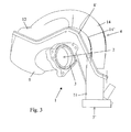
- the manifold or distributor 1 comprises, on the one hand, an intake or plenum chamber 2 of elongate shape and provided at one of its longitudinal ends with an intake aperture 3 and, on the other hand, at least two pipes 4 laterally connected to said chamber 2, said pipes 4 extending at least partially around said intake chamber 2 from their inlet apertures 5 opening therein and having a curved structure over at least a portion of their length.
- the invention allows the manifold 2 to be cut into only two constituent parts 6 and 7.
- a first conduit segment 11 formed from one piece and being part of the first part 6 is observed first, then a second conduit segment formed by longitudinal joining of two side portions of complementary walls 10 and 14 respectively belonging to the first constituent part 6 and the second constituent part 7 and, finally, a third conduit segment 13 formed in one piece and forming part of the second part 7.
- each pipe 4 has an inlet aperture 5 region formed by a one piece duct portion and an outlet aperture 5 region also formed by a one piece duct portion, the medium segment of each pipe 4 being formed by two half shells joined together by joint zones 8 of important size contributing to the overall strength, resistance and rigidity of the manifold.
- the first longitudinal portion 9 corresponds to a main portion of the casing defining the intake chamber 2 and comprises a connecting piece in one piece 9' defining the intake aperture 3, and the second longitudinal part 12 corresponds to a cover closing said first longitudinal portion 9, the joining surface 8' extending mainly below the neutral fibres or the central axes of circulation of the pipes 4 (see Figs. 2, 3 and 5).
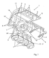
- the pipes 4 may be connected to one another, between adjacent pipes, by connecting portions 15 in the form of plates or strips formed in one piece with the constituent parts 6, 7, on the one hand for the second part 7, at least in the region of the end conduit segments 13 of the pipes 4 opening into the intake chamber 2 and, if necessary, of the longitudinal edges 14' of the complementary intermediate portions 14 of side wall portions of the pipes 4 and, on the other hand for the first portion 6, in the region of the end conduit segment 11 of the pipes 4 defining the outlet apertures 5' and, if necessary, of the longitudinal edges 10' of the complementary intermediate portions 10 of side wall portions of the pipes 4, these connecting portions 15 forming an assembly and/or fixing flange 15' in one piece in the region of the end conduit segments 11 defining the outlet apertures 5'.
- connecting portions 15 of the intermediate portions 10, 14 of lateral wall portions of pipes 4 of the first and second parts 6 and 7 thus form portions of peripheral joint zones 8.
- a portion of the second longitudinal portion of the casing forming the cover 12 also forms a portion of the walls of the end conduit segments 13 of said pipes 4 ending in the respective inlet apertures 5
- the end conduit segments 13 of the pipes 4 opening into the intake chamber 2 comprise curved circulation axes located in respective mutually parallel planes, the segments 13 being obtained by moulding by means of a rotary core.
- the segments of the conduits 13 of the pipes 4 opening into the intake chamber 2 comprise curved circulation axes with helical development, these segments being obtained by moulding by means of a rotary core displaced with a combined rotational and translatory movement.
- the end conduit segments 13 of the pipes 4 opening into the intake chamber 2 comprise circulation axes which are substantially rectilinear and located in respective mutually parallel planes, the segments 13 being obtained by moulding by means of a core displaced in translation, optionally in two different directions.
- the invention also relates to a method of producing an intake manifold or distributor 1 as described above, characterised in that it consists in separately producing the first part 6 and the second part 7 by injection moulding of thermoplastic material, whether reinforced or not, the second part 7 optionally being produced by a mould with a rotary core, then joining these two parts 6 and 7 by vibration welding in the region of the peripheral joint zones 8.
- joint zones 8 constitute together a continuous and closed pattern comprised of four closed joint segments, one for each pipe 4, and of one closed joint segment defining the assembling region of the two shell parts 9 and 12 forming together the walls of the intake chamber 2.
- This particular layout of the joint zones 8, with in particular a continuous joint region 8" shared by the joint zones of the pipes 4 and the joint zone of the intake chamber, provides an increased mechanical resistance and rigidity to said intake manifold.
Landscapes
- Engineering & Computer Science (AREA)
- Mechanical Engineering (AREA)
- Chemical & Material Sciences (AREA)
- Combustion & Propulsion (AREA)
- General Engineering & Computer Science (AREA)
- Manufacturing & Machinery (AREA)
- Injection Moulding Of Plastics Or The Like (AREA)
- Characterised By The Charging Evacuation (AREA)
- Moulds For Moulding Plastics Or The Like (AREA)
Abstract
Description
Claims (9)
- Intake manifold or distributor for an air feed circuit for an internal-combustion engine comprising, on the one hand, an intake or plenum chamber of elongate shape and provided at one of its longitudinal ends with an intake aperture and, on the other hand, at least two pipes laterally connected to said chamber, said pipes extending at least partially around said intake chamber from their inlet apertures opening therein and having a curved structure over at least a portion of their length, the manifold being characterised in that it consists of two parts (6 and 7) produced by injection moulding of thermoplastic material and joined to one another in the region of peripheral joint zones (8) located on a joining surface (8') crossing said manifold (1), a first part (6) in one piece forming a first longitudinal portion (9) of the casing defining the intake chamber (2), an intermediate portion (10) of a side portion of the wall of each of the various pipes (4) and an end conduit segment (11) of each of said pipes (4) ending in the outlet aperture (5') of each of them, and a second part (7) in one piece forming a second complementary longitudinal portion (12) of the casing defining the intake chamber (2), an end conduit segment (13) of each of said pipes (4) ending with the inlet aperture (5) of each of these pipes (4) opening into the intake chamber (2) and a complementary intermediate portion (14) of a side portion of the wall of each of the pipes (4).
- Manifold according to claim 1, characterised in that the first longitudinal portion (9) corresponds to a main portion of the casing defining the intake chamber (2) and comprises a joining piece in one piece (9') defining the intake aperture (3) and in that the second longitudinal portion (12) corresponds to a cover closing said first longitudinal portion (9), the joining surface (8') extending mainly below the neutral fibres or the central axes of circulation of the pipes (4).
- Manifold according to either of claims 1 to 2, characterised in that the pipes (4) are connected to one another, between adjacent pipes, by connecting portions (15) in the form of plates or strips formed in one piece with the constituent parts (6, 7), on the one hand for the second part (7), at least in the region of the end conduit segments (13) of the pipes (4) opening into the intake chamber (2) and, if necessary, of the longitudinal edges (14') of the complementary intermediate portions (14) of side wall portions of the pipes (4) and, on the other hand for the first part (6), in the region of the end conduit segments (11) of the pipes (4) defining the outlet apertures (5') and, if necessary, of the longitudinal edges (10') of the complementary intermediate portions (10) of side wall portions of the pipes (4), these connecting portions (5) forming an assembly and/or fixing flange (15') in one piece in the region of the end conduit segments (11) defining the outlet apertures (5').
- Manifold according to claim 3, characterised in that the connecting portions (15) of the intermediate portions (10, 14) of side wall portions of pipes (4) of the first and second parts (6 and 7) form portions of peripheral joint zones (8).
- Manifold according to any one of claims 2 to 4, characterised in that a portion of the second longitudinal portion of the casing forming the cover (12) also forms a portion of the walls of the end conduit segments (13) of said pipes (4) ending in the respective inlet apertures (5).
- Manifold according to any one of claims 1 to 5, characterised in that the end conduit segments (13) of the pipes (4) opening into the intake chamber (2) comprise circulation axes which are substantially rectilinear and located in respective mutually parallel planes, the segments (13) being obtained by moulding by means of a core displaced in translation, optionally in two different directions.
- Manifold according to any one of claims 1 to 5, characterised in that the end conduit segments (13) of the pipes (4) opening into the intake chamber (2) comprise curved circulation axes located in respective mutually parallel planes, these segments (13) being obtained by moulding by means of a rotary core.
- Manifold according to any one of claims 1 to 5, characterised in that the segments of the conduits (13) of the pipes (4) opening into the intake chamber (2) comprise curved circulation axes with a helical development, these segments being obtained by moulding by means of a rotary core displaced with a combined rotational and translatory movement.
- Method for producing an intake manifold or distributor according to any one of claims 1 to 8, characterised in that it consists in separately producing the first part (6) and the second part (7) by injection moulding of thermoplastic material, whether reinforced or not, the second part (7) optionally being produced by a mould with a rotary core, then joining these two parts (6 and 7) by vibration welding in the region of peripheral joint zones (8).
Applications Claiming Priority (2)
| Application Number | Priority Date | Filing Date | Title |
|---|---|---|---|
| FR0214544A FR2847307B1 (en) | 2002-11-20 | 2002-11-20 | INTAKE MANIFOLD IN TWO PARTS |
| FR0214544 | 2002-11-20 |
Publications (2)
| Publication Number | Publication Date |
|---|---|
| EP1422414A1 true EP1422414A1 (en) | 2004-05-26 |
| EP1422414B1 EP1422414B1 (en) | 2007-01-17 |
Family
ID=32187778
Family Applications (1)
| Application Number | Title | Priority Date | Filing Date |
|---|---|---|---|
| EP03026654A Revoked EP1422414B1 (en) | 2002-11-20 | 2003-11-19 | Intake manifold in two parts |
Country Status (4)
| Country | Link |
|---|---|
| US (1) | US7017543B2 (en) |
| EP (1) | EP1422414B1 (en) |
| DE (1) | DE60311216T2 (en) |
| FR (1) | FR2847307B1 (en) |
Cited By (1)
| Publication number | Priority date | Publication date | Assignee | Title |
|---|---|---|---|---|
| EP1522717A1 (en) | 2003-10-10 | 2005-04-13 | Nissan Motor Company, Limited | Intake arrangement for internal combustion engine |
Families Citing this family (17)
| Publication number | Priority date | Publication date | Assignee | Title |
|---|---|---|---|---|
| US7055499B1 (en) * | 2000-11-17 | 2006-06-06 | Hitachi, Ltd. | Internal module, members of the module, and electronic controlled throttle device for internal combustion engine |
| USD533194S1 (en) * | 2005-11-05 | 2006-12-05 | Momar Injection Inc. | Intake manifold set |
| US7216620B1 (en) * | 2006-02-13 | 2007-05-15 | Mann & Hummel Gmbh | Engine lower intake manifold and method for making the same |
| FR2949823B1 (en) * | 2009-09-04 | 2013-05-10 | Mark Iv Systemes Moteurs Sa | DISTRIBUTOR INTEGRATING A GAS DRAINAGE CIRCUIT OF THE CARTER AND VEHICLE COMPRISING SUCH A DIVIDER |
| DE102010038440A1 (en) | 2010-07-27 | 2012-02-02 | Montaplast Gmbh | Suction pipe for combustion engine of vehicle, has inlet chamber that includes inlet port which is integrally formed with exhaust passages connected to cylinders of engine, and flange |
| JP6175274B2 (en) | 2013-05-15 | 2017-08-02 | 株式会社Subaru | Manufacturing method of intake manifold |
| KR101470167B1 (en) * | 2013-06-13 | 2014-12-05 | 현대자동차주식회사 | Intake system for engine |
| JP6376855B2 (en) * | 2014-06-13 | 2018-08-22 | 株式会社マーレ フィルターシステムズ | Intake manifold |
| US10208721B2 (en) | 2017-03-15 | 2019-02-19 | Brp-Rotax Gmbh & Co. Kg | Method and system for manufacturing a family of intake manifolds for a family of internal combustion engines |
| USD927551S1 (en) * | 2017-03-21 | 2021-08-10 | Holley Performance Products, Inc. | Adapter |
| JP7021938B2 (en) * | 2017-12-27 | 2022-02-17 | 株式会社マーレ フィルターシステムズ | Synthetic resin manifold for internal combustion engine |
| US10815945B2 (en) | 2018-01-15 | 2020-10-27 | Ford Global Technologies, Llc | Integral intake manifold |
| US20190219012A1 (en) * | 2018-01-15 | 2019-07-18 | Ford Global Technologies, Llc | Integral intake manifold |
| US10801448B2 (en) | 2018-01-15 | 2020-10-13 | Ford Global Technologies, Llc | Integral intake manifold |
| US10808657B2 (en) * | 2018-02-02 | 2020-10-20 | Ford Global Technologies, Llc | Vehicle component with an accessory mounting feature and a method and tool for forming |
| USD880528S1 (en) * | 2019-04-18 | 2020-04-07 | Oliver Matt Shurdim | Intake manifold pair |
| JP7582072B2 (en) | 2021-05-26 | 2024-11-13 | マツダ株式会社 | Intake manifold structure |
Citations (7)
| Publication number | Priority date | Publication date | Assignee | Title |
|---|---|---|---|---|
| US4784185A (en) * | 1986-04-03 | 1988-11-15 | Flifa-Fahrzeugteile Gmbh & Co. | Pipe for gases and liquid with screw flange |
| EP0432919A1 (en) * | 1989-12-12 | 1991-06-19 | Rover Group Limited | An internal combustion engine inlet manifold |
| GB2279035A (en) * | 1991-01-22 | 1994-12-21 | Rover Group | Fabrication of an internal combustion engine inlet manifold |
| FR2712636A1 (en) * | 1993-11-17 | 1995-05-24 | Orbey Plastiques Ind | Mfr. technique for producing fuel/air distribution manifold for vehicle engine |
| US5851456A (en) * | 1993-10-04 | 1998-12-22 | Fuji Jukogyo Kabushiki Kaisha | Method for manufacturing a multi-layer plastic product |
| US20020050261A1 (en) * | 2000-10-31 | 2002-05-02 | Yutaka Miyahara | Resin intake manifolds and manufacturing process thereof |
| WO2002081899A1 (en) * | 2001-04-04 | 2002-10-17 | Dow Global Technologies Inc. | Adhesively bonded engine intake manifold assembly |
Family Cites Families (4)
| Publication number | Priority date | Publication date | Assignee | Title |
|---|---|---|---|---|
| US4175504A (en) * | 1975-01-15 | 1979-11-27 | Bayerische Motoren Werke Ag | Air induction system for an internal combustion engine |
| GB1602310A (en) * | 1978-05-30 | 1981-11-11 | Ford Motor Co | Manifolds for internal combustion engines |
| US4805564A (en) * | 1987-09-22 | 1989-02-21 | Sharon Manufacturing Company | Engine intake manifold assembly |
| DE10119280A1 (en) * | 2001-04-20 | 2002-11-07 | Mann & Hummel Filter | suction |
-
2002
- 2002-11-20 FR FR0214544A patent/FR2847307B1/en not_active Expired - Fee Related
-
2003
- 2003-11-19 DE DE60311216T patent/DE60311216T2/en not_active Revoked
- 2003-11-19 EP EP03026654A patent/EP1422414B1/en not_active Revoked
- 2003-11-20 US US10/717,818 patent/US7017543B2/en not_active Expired - Fee Related
Patent Citations (7)
| Publication number | Priority date | Publication date | Assignee | Title |
|---|---|---|---|---|
| US4784185A (en) * | 1986-04-03 | 1988-11-15 | Flifa-Fahrzeugteile Gmbh & Co. | Pipe for gases and liquid with screw flange |
| EP0432919A1 (en) * | 1989-12-12 | 1991-06-19 | Rover Group Limited | An internal combustion engine inlet manifold |
| GB2279035A (en) * | 1991-01-22 | 1994-12-21 | Rover Group | Fabrication of an internal combustion engine inlet manifold |
| US5851456A (en) * | 1993-10-04 | 1998-12-22 | Fuji Jukogyo Kabushiki Kaisha | Method for manufacturing a multi-layer plastic product |
| FR2712636A1 (en) * | 1993-11-17 | 1995-05-24 | Orbey Plastiques Ind | Mfr. technique for producing fuel/air distribution manifold for vehicle engine |
| US20020050261A1 (en) * | 2000-10-31 | 2002-05-02 | Yutaka Miyahara | Resin intake manifolds and manufacturing process thereof |
| WO2002081899A1 (en) * | 2001-04-04 | 2002-10-17 | Dow Global Technologies Inc. | Adhesively bonded engine intake manifold assembly |
Cited By (1)
| Publication number | Priority date | Publication date | Assignee | Title |
|---|---|---|---|---|
| EP1522717A1 (en) | 2003-10-10 | 2005-04-13 | Nissan Motor Company, Limited | Intake arrangement for internal combustion engine |
Also Published As
| Publication number | Publication date |
|---|---|
| US20040154574A1 (en) | 2004-08-12 |
| DE60311216T2 (en) | 2007-10-31 |
| EP1422414B1 (en) | 2007-01-17 |
| DE60311216D1 (en) | 2007-03-08 |
| FR2847307A1 (en) | 2004-05-21 |
| US7017543B2 (en) | 2006-03-28 |
| FR2847307B1 (en) | 2007-03-02 |
Similar Documents
| Publication | Publication Date | Title |
|---|---|---|
| EP1422414B1 (en) | Intake manifold in two parts | |
| US5642697A (en) | Intake manifold for an internal combustion engine | |
| JPH07229454A (en) | Integrated suction system | |
| US6234132B1 (en) | Intake system of thermoplastic plastics | |
| JP2000505168A (en) | Thermoplastic suction device | |
| JP2009008004A (en) | Intake manifold for internal combustion engine | |
| JPS5840644B2 (en) | Intake system for multi-cylinder internal combustion engines | |
| JP3964690B2 (en) | Synthetic resin manifolds for internal combustion engines | |
| US6571759B2 (en) | Resin intake manifolds and manufacturing process thereof | |
| US4409934A (en) | Inlet supply manifold for combustion engine with 4- to 6-cylinders in line | |
| US5901988A (en) | Structure for coupling pipe with breeches pipe | |
| JP6639215B2 (en) | Intake manifold | |
| JPH10187162A (en) | Resonator | |
| EP2014906B1 (en) | Double-plenum inlet manifold and vehicle incorporating such a manifold | |
| WO1998049440A1 (en) | Integrated duct and resonator for an automobile engine air induction system | |
| JP4381106B2 (en) | Intake device for internal combustion engine | |
| US7047926B2 (en) | Intake manifold or distributor for the thermal engine of a vehicle and production process thereof | |
| JP7107086B2 (en) | Intake duct for internal combustion engine | |
| JPH09250408A (en) | Intake pipe arrangement structure in intake device of internal combustion engine | |
| JPH0332779Y2 (en) | ||
| JP7746904B2 (en) | Engine intake system | |
| JPH10299592A (en) | Intake device for internal combustion engine | |
| JPH10299590A (en) | Synthetic resin intake manifold | |
| JP2003314391A (en) | Intake manifold and molding method thereof | |
| JPH0141899Y2 (en) |
Legal Events
| Date | Code | Title | Description |
|---|---|---|---|
| PUAI | Public reference made under article 153(3) epc to a published international application that has entered the european phase |
Free format text: ORIGINAL CODE: 0009012 |
|
| AK | Designated contracting states |
Kind code of ref document: A1 Designated state(s): AT BE BG CH CY CZ DE DK EE ES FI FR GB GR HU IE IT LI LU MC NL PT RO SE SI SK TR |
|
| AX | Request for extension of the european patent |
Extension state: AL LT LV MK |
|
| 17P | Request for examination filed |
Effective date: 20041125 |
|
| AKX | Designation fees paid |
Designated state(s): DE GB IT |
|
| 17Q | First examination report despatched |
Effective date: 20050302 |
|
| GRAP | Despatch of communication of intention to grant a patent |
Free format text: ORIGINAL CODE: EPIDOSNIGR1 |
|
| GRAS | Grant fee paid |
Free format text: ORIGINAL CODE: EPIDOSNIGR3 |
|
| GRAA | (expected) grant |
Free format text: ORIGINAL CODE: 0009210 |
|
| AK | Designated contracting states |
Kind code of ref document: B1 Designated state(s): DE GB IT |
|
| REG | Reference to a national code |
Ref country code: GB Ref legal event code: FG4D |
|
| REF | Corresponds to: |
Ref document number: 60311216 Country of ref document: DE Date of ref document: 20070308 Kind code of ref document: P |
|
| PLBI | Opposition filed |
Free format text: ORIGINAL CODE: 0009260 |
|
| PLAX | Notice of opposition and request to file observation + time limit sent |
Free format text: ORIGINAL CODE: EPIDOSNOBS2 |
|
| 26 | Opposition filed |
Opponent name: MANN + HUMMEL GMBH Effective date: 20071017 |
|
| PLAF | Information modified related to communication of a notice of opposition and request to file observations + time limit |
Free format text: ORIGINAL CODE: EPIDOSCOBS2 |
|
| PLBB | Reply of patent proprietor to notice(s) of opposition received |
Free format text: ORIGINAL CODE: EPIDOSNOBS3 |
|
| PGFP | Annual fee paid to national office [announced via postgrant information from national office to epo] |
Ref country code: IT Payment date: 20081120 Year of fee payment: 6 |
|
| PGFP | Annual fee paid to national office [announced via postgrant information from national office to epo] |
Ref country code: GB Payment date: 20081119 Year of fee payment: 6 |
|
| RDAF | Communication despatched that patent is revoked |
Free format text: ORIGINAL CODE: EPIDOSNREV1 |
|
| PGFP | Annual fee paid to national office [announced via postgrant information from national office to epo] |
Ref country code: DE Payment date: 20091223 Year of fee payment: 7 |
|
| RDAG | Patent revoked |
Free format text: ORIGINAL CODE: 0009271 |
|
| STAA | Information on the status of an ep patent application or granted ep patent |
Free format text: STATUS: PATENT REVOKED |
|
| GBPC | Gb: european patent ceased through non-payment of renewal fee |
Effective date: 20091119 |
|
| 27W | Patent revoked |
Effective date: 20100311 |
|
| PG25 | Lapsed in a contracting state [announced via postgrant information from national office to epo] |
Ref country code: GB Free format text: LAPSE BECAUSE OF NON-PAYMENT OF DUE FEES Effective date: 20091119 |
|
| PG25 | Lapsed in a contracting state [announced via postgrant information from national office to epo] |
Ref country code: IT Free format text: LAPSE BECAUSE OF NON-PAYMENT OF DUE FEES Effective date: 20091119 |