EP1422353B1 - Inspektionsschacht und Verfahren - Google Patents
Inspektionsschacht und Verfahren Download PDFInfo
- Publication number
- EP1422353B1 EP1422353B1 EP03257356A EP03257356A EP1422353B1 EP 1422353 B1 EP1422353 B1 EP 1422353B1 EP 03257356 A EP03257356 A EP 03257356A EP 03257356 A EP03257356 A EP 03257356A EP 1422353 B1 EP1422353 B1 EP 1422353B1
- Authority
- EP
- European Patent Office
- Prior art keywords
- boundary box
- water
- valves
- guard tube
- tube
- Prior art date
- Legal status (The legal status is an assumption and is not a legal conclusion. Google has not performed a legal analysis and makes no representation as to the accuracy of the status listed.)
- Expired - Lifetime
Links
- 238000000034 method Methods 0.000 title claims description 12
- XLYOFNOQVPJJNP-UHFFFAOYSA-N water Substances O XLYOFNOQVPJJNP-UHFFFAOYSA-N 0.000 claims abstract description 85
- 238000009434 installation Methods 0.000 claims abstract description 3
- 230000002745 absorbent Effects 0.000 description 1
- 239000002250 absorbent Substances 0.000 description 1
- 238000009412 basement excavation Methods 0.000 description 1
- 230000006835 compression Effects 0.000 description 1
- 238000007906 compression Methods 0.000 description 1
- 239000006260 foam Substances 0.000 description 1
- 238000009413 insulation Methods 0.000 description 1
- 238000012986 modification Methods 0.000 description 1
- 230000004048 modification Effects 0.000 description 1
- 230000000717 retained effect Effects 0.000 description 1
- 230000007704 transition Effects 0.000 description 1
- 238000011144 upstream manufacturing Methods 0.000 description 1
Images


Classifications
-
- E—FIXED CONSTRUCTIONS
- E03—WATER SUPPLY; SEWERAGE
- E03B—INSTALLATIONS OR METHODS FOR OBTAINING, COLLECTING, OR DISTRIBUTING WATER
- E03B7/00—Water main or service pipe systems
- E03B7/07—Arrangement of devices, e.g. filters, flow controls, measuring devices, siphons or valves, in the pipe systems
- E03B7/072—Arrangement of flowmeters
-
- E—FIXED CONSTRUCTIONS
- E03—WATER SUPPLY; SEWERAGE
- E03B—INSTALLATIONS OR METHODS FOR OBTAINING, COLLECTING, OR DISTRIBUTING WATER
- E03B7/00—Water main or service pipe systems
- E03B7/09—Component parts or accessories
- E03B7/095—Component holders or housings, e.g. boundary boxes
-
- G—PHYSICS
- G01—MEASURING; TESTING
- G01F—MEASURING VOLUME, VOLUME FLOW, MASS FLOW OR LIQUID LEVEL; METERING BY VOLUME
- G01F15/00—Details of, or accessories for, apparatus of groups G01F1/00 - G01F13/00 insofar as such details or appliances are not adapted to particular types of such apparatus
- G01F15/005—Valves
-
- G—PHYSICS
- G01—MEASURING; TESTING
- G01F—MEASURING VOLUME, VOLUME FLOW, MASS FLOW OR LIQUID LEVEL; METERING BY VOLUME
- G01F15/00—Details of, or accessories for, apparatus of groups G01F1/00 - G01F13/00 insofar as such details or appliances are not adapted to particular types of such apparatus
- G01F15/10—Preventing damage by freezing or excess pressure or insufficient pressure
-
- G—PHYSICS
- G01—MEASURING; TESTING
- G01F—MEASURING VOLUME, VOLUME FLOW, MASS FLOW OR LIQUID LEVEL; METERING BY VOLUME
- G01F15/00—Details of, or accessories for, apparatus of groups G01F1/00 - G01F13/00 insofar as such details or appliances are not adapted to particular types of such apparatus
- G01F15/18—Supports or connecting means for meters
-
- G—PHYSICS
- G01—MEASURING; TESTING
- G01F—MEASURING VOLUME, VOLUME FLOW, MASS FLOW OR LIQUID LEVEL; METERING BY VOLUME
- G01F15/00—Details of, or accessories for, apparatus of groups G01F1/00 - G01F13/00 insofar as such details or appliances are not adapted to particular types of such apparatus
- G01F15/18—Supports or connecting means for meters
- G01F15/185—Connecting means, e.g. bypass conduits
-
- E—FIXED CONSTRUCTIONS
- E02—HYDRAULIC ENGINEERING; FOUNDATIONS; SOIL SHIFTING
- E02D—FOUNDATIONS; EXCAVATIONS; EMBANKMENTS; UNDERGROUND OR UNDERWATER STRUCTURES
- E02D29/00—Independent underground or underwater structures; Retaining walls
- E02D29/12—Manhole shafts; Other inspection or access chambers; Accessories therefor
- E02D29/14—Covers for manholes or the like; Frames for covers
- E02D29/1409—Covers for manholes or the like; Frames for covers adjustable in height or inclination
Definitions
- the present invention relates to a boundary box and to a method of removing a valve from a boundary box.
- a boundary box provides the connection point between the mains water supply and a property to be supplied with water.
- FIG 1 of the drawings there is shown a prior art boundary box 1.
- the boundary box 1 is positioned in a pit which is dug outside the property to be supplied with water.
- the boundary box 1 has a base 2 which is placed at the bottom of the pit.
- a tubular outer guard tube 3 of circular cross-section is open at its lower and upper ends. The lower end fits into the base 2.
- the example shown in Figure 1 has a telescopic inner sleeve 4 which fits inside the outer guard tube 3 to allow the overall height of the boundary box 1 to be adjusted.
- the example shown in Figure 1 has a tiltable lid 5 which allows the upper surface of the lid 5 to be positioned to be flush with the ground.
- a water inlet connection 6 at the bottom of the boundary box 1 provides a connection point to the mains water supply.
- Water entering the inlet connection point 6 passes through an inlet tube 7 to a stop valve 8 which can be operated by a key 9 which is accessible through the top of the boundary box 1 in order to allow the water supply through the boundary box 1 to be shut off as and when required.
- Water flowing through the stop valve 8 passes through a manifold 10 which has a connection point 11 to which equipment such as a water meter, filter, water sampler, etc. may optionally be fitted. Water then flows, optionally via a non-return valve (not shown), through an outlet pipe 12 which passes through an outlet connection point 13 to the property to be supplied with water.
- the inlet and outlet tubes 7,12 are retained rigidly by a mounting bracket 14 in the base 2.
- the stop valve 8 and manifold 10 are securely fixed to a mounting bracket 15 provided in the base 2 of the boundary box 1 by nuts 16 which are tightened up against the under surface of the mounting bracket 15.
- GB-A-2310683 discloses an example of a boundary box of the general type discussed above.
- GB-A-2194576 discloses a base unit for an underground stopcock housing having a tunnel through which a stopcock extends.
- US-A-5303583 discloses another example of a boundary box.
- a boundary box for installation in a pit to allow water to be supplied to a property
- the boundary box comprising: a guard tube, the guard tube containing one or more valves that control the flow of water from a water supply through the boundary box to a property to be supplied with water, the guard tube having an opening to allow access to said one or more valves; and, a water inlet tube for conveying water from a mains water supply into the boundary box; said one or more valves being mounted in the guard tube by a fitting that allows said one or more valves to be secured in the guard tube and removed from the guard tube by a manual operation through the opening in the guard tube without requiring the boundary box to be removed from a said pit; characterised by: a check valve at the upper end of the water inlet tube for preventing flow of water therethrough when the or one of the removable valves is removed from the boundary box.
- the fitting for said one or more valves is arranged to be operable by rotation of said one or more valves to selectively secure said one or more valves in the guard tube and release said one or more valves from the guard tube.
- the fitting conveniently comprises a bayonet connection between said one or more valves and the guard tube.
- a screw fitting or the like may be used.
- the boundary box may comprise plural said valves each of which is independently mounted in the guard tube by a respective fitting that allows each valve to be secured in and removed independently from the guard tube by a manual operation through the opening in the guard tube without requiring the boundary box to be removed from a said pit.
- the boundary box comprises a water outlet tube for conveying water from the boundary box to a property, the water outlet tube having a check valve for preventing flow of water therethrough when the or one of the removable valves is removed from the boundary box.
- a method of replacing a valve in a boundary box installed in a pit comprising a guard tube and a water inlet tube for conveying water from a mains water supply into the boundary box, the guard tube containing one or more valves that control the flow of water from a water supply through the boundary box to a property to be supplied with water, the guard tube having an opening to allow access to said one or more valves, said one or more valves being mounted in the guard tube by a fitting, the boundary box having a check valve at the upper end of the water inlet tube for preventing flow of water therethrough when the or one of the removable valves is removed from the boundary box
- the method comprising: removing a valve from the guard tube by a manual operation of the fitting through the opening in the guard tube without removing the boundary box from the pit; and securing a replacement valve in the guard tube by a manual operation of the fitting through the opening in the guard tube without removing the boundary box from the pit; the check valve
- the method preferably comprises operating the fitting by rotating said valve.
- the fitting conveniently comprises a bayonet connection between said valve and the guard tube.
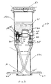
- a boundary box 20 has a base 21 on which a guard tube 22 is supported.
- the guard tube 22 is formed of three tubular portions 22a,22b,22c arranged in series from the base 21 to the upper end of the boundary box 20.
- the lowermost portion 22a is of circular cross-section and the uppermost portion 22c is of oval cross-section, the middle portion 22b providing a transition between the circular and oval cross-sections.
- the uppermost portion 22c is slidably mounted on the middle portion 22b to provide for telescopic adjustment of the overall height of the boundary box 20.
- a detachable lid 23 sealingly closes the open upper end of the guard tube 22.
- the lowermost portion 22a of the guard tube 22 has openings 24,25 on opposed sides for a water inlet tube 26 and a water outlet tube 27 respectively.
- the middle portion 22b of the guard tube 22 has fittings that support the parts of the boundary box 20 that are most likely to have to be replaced in practice.
- Such parts are typically a stop valve 28 on the water supply side of the boundary box and a non-return valve 29 on the property side of the boundary box 20. It will be understood that these are the main pressure-bearing components of the boundary box 20.
- the stop valve 28 is manually operable by rotation of a key 28' on the top of the stop valve 28, access being had through the upper end of the boundary box 20.
- a water meter (not shown in Figure 2 but visible in Figure 3 ) is in practice fitted between the stop valve 28 and the non-return valve 29.
- the fitting for the removable parts is such that the stop and non-return valves 28,29 can be removed from the guard tube 20 by a manual operation through the open upper end of the guard tube 22, the lid 23 being temporarily removed for this purpose.
- This arrangement avoids the need to excavate and remove the whole of the boundary box 20 from the pit in which it is installed.
- the fitting for the stop and non-return valves 28,29 is in each case a bayonet-type fitting.
- channels 30,31 are integrally formed on the inner surface of the middle portion 22b of the guard tube 22.
- Each of the outer walls of the housings of the stop and non-return valves 28,29 has two outwardly projecting opposed lugs 32,33.
- any other arrangement for fixing the stop and/or the non-return valve 28,29 in the boundary box 20, such that the valve 28,29 can be removed by a manual operation through the open upper end of the boundary box 20, can be used instead of the bayonet-type fitting described above.
- a screw threaded arrangement could be provided.
- a respective check valve 34,35 is provided at the upper end of each of the water inlet and outlet tubes 26,27 in the region of the bayonet housing channels 30,31, i.e. upstream of the stop valve 28 and downstream of the non-return valve 29 respectively.
- a respective spigot 36,37 at the lower end of each of the stop valve 28 and non-return valve 29 projects downwardly.
- These spigots 36,37 open the respective check valves 34,35 when the stop valve 28 and non-return valve 29 are fitted into the bayonet housing channels 30,31, thereby allowing water to flow through the boundary box 20.
- withdrawal of the spigot 36,37 allows the corresponding check valve 34,35 to close, thereby preventing water entering the boundary box 20 from the mains water supply and/or from the property.
- FIG 3 shows a second example of a boundary box 20 in accordance with an embodiment of the present invention.
- This example is very similar to the first example, and the same reference numerals have been used to indicate the same or corresponding parts.
- the main difference in this example is that the bayonet housing channels 30,31 and correspondingly the lugs 32,33 of the valves 28,29 are positioned 90° around a vertical axis compared to the example of Figure 2 such that the lugs 32,33 and the channels 30,31 are not visible in Figure 3.
- Figure 3 however shows a water meter 40 fitted between the stop valve 28 and the non-return valve 29, the fitting for the meter 40 being the same in the first and second examples of the boundary box 20.
- a non-absorbent foam insulation pack 41 is also shown in Figure 3 fitted over the water meter 40 and valves 28,29.
- a spring-loaded piston 42 projects towards the housing of the non-return valve 29.
- the piston 42 is hollow and biased outwardly, towards the non-return valve 29, by a coil compression spring 43.
- One or more O-ring seals 44 may be provided around the piston 42 to seal the piston 42 in the mouth of the housing of the stop valve 28.
- the piston 42 is pushed against the loading of the spring 43 (i.e. pushed to the left in the drawings), optionally by using a special tool which can be inserted through the open upper end of the boundary box 20.
- the water meter 40 is then offered up to the housings of the stop and non-return valves 28,29.
- the exit tube 45 of the water meter is then fitted into the corresponding inlet of the housing of the non-return valve 29.
- the inlet tube 46 of the water meter 40 is inserted into the hollow interior of the piston 42.
- O-rings 47,48 may be provided in the facing end of the piston 42 and the inlet tube of the housing of the non-return valve 29 in order to seal the connections with the water meter 40.
- the spring-loaded piston 42 takes up any slack or tolerance and thus ensures a good, watertight connection between the water meter 40 and the other water-carrying components of the boundary box 20.
- the spring-loaded piston 42 also enables quick removal and therefore replacement of the water meter 40, it being understood that removal of the water meter 40 is carried out by carrying out the above steps in reverse.
- the stop valve 28 is operated to prevent and enable water to flow from the mains water supply into the boundary box as necessary during fitting and removal of the water meter 40.
Landscapes
- Physics & Mathematics (AREA)
- General Physics & Mathematics (AREA)
- Fluid Mechanics (AREA)
- Public Health (AREA)
- Health & Medical Sciences (AREA)
- Water Supply & Treatment (AREA)
- Hydrology & Water Resources (AREA)
- Engineering & Computer Science (AREA)
- Life Sciences & Earth Sciences (AREA)
- Measuring Volume Flow (AREA)
- Check Valves (AREA)
- Golf Clubs (AREA)
- Investigating Or Analyzing Materials By The Use Of Ultrasonic Waves (AREA)
- Investigating Materials By The Use Of Optical Means Adapted For Particular Applications (AREA)
- Ultra Sonic Daignosis Equipment (AREA)
- Paper (AREA)
- Control Of Motors That Do Not Use Commutators (AREA)
Claims (8)
- Inspektionsschacht (20) zur Installation in einer Grube, um die Zufuhr von Wasser an eine Immobilie (einen Grundbesitz) zu ermöglichen, wobei der Inspektionsschacht (20) umfasst:ein Schutzrohr (22), wobei das Schutzrohr (22) eines oder mehrere Ventile (28, 29) enthält, das bzw. die den Wasserfluss von einer Wasserversorgung durch den Inspektionsschacht (20) an eine mit Wasser zu versorgende Immobilie steuert bzw. steuern, wobei das Schutzrohr (22) eine Öffnung hat, um einen Zugriff auf das Ventil oder die Ventile (28, 29) zu ermöglichen; undein Wassereinlassrohr (26) zum Leiten von Wasser von einem Wasserversorgungsnetz in den Inspektionsschacht (20);wobei das Ventil oder die Ventile (28, 29) in dem Schutzrohr (22) durch ein Anschlussstück (30, 31, 32, 33) befestigt sind, welches ermöglicht, dass das Ventil oder die Ventile (28, 29) durch eine manuelle Betätigung über die Öffnung in dem Schutzrohr (22) in dem Schutzrohr (22) gesichert und aus dem Schutzrohr (22) entfernt wird bzw. werden, ohne dass der Inspektionsschacht (20) aus der Grube entfernt werden muss, gekennzeichnet durch:ein Rückschlagventil (34) an dem oberen Ende des Wassereinlassrohrs (26) zum Verhindern, dass Wasser durch dieses hindurchfließt, wenn das oder eines der entfernbaren Ventile (28, 29) aus dem Inspektionsschacht entfernt wird.
- Inspektionsschacht (20) nach Anspruch 1, wobei das Anschlussstück (30, 31, 32, 33) für das Ventil oder die Ventile (28, 29) so angeordnet ist, dass es durch Drehen des Ventils oder der Ventile (28, 29) betätigt werden kann, um das Ventil oder die Ventile (28, 29) in dem Schutzrohr (22) selektiv zu sichern und das Ventil oder die Ventile (28, 29) von dem Schutzrohr (22) zu lösen.
- Inspektionsschacht (20) nach Anspruch 2, wobei das Anschlussstück (30, 31, 32, 33) eine Bajonettverbindung (30, 31, 32, 33) zwischen dem Ventil oder den Ventilen (28, 29) und dem Schutzrohr (22) umfasst.
- Inspektionsschacht (20) nach einem der Ansprüche 1 bis 3, umfassend eine Mehrzahl der Ventile (28, 29), die jeweils einzeln in dem Schutzrohr (22) über ein entsprechendes Anschlussstück (30, 31, 32, 33) befestigt sind, welches es ermöglicht, dass jedes Ventil (28, 29) durch eine manuelle Betätigung über die Öffnung in dem Schutzrohr (22) einzeln in dem Schutzrohr (22) gesichert und aus dem Schutzrohr (22) entfernt werden kann, ohne dass der Inspektionsschacht (20) aus der Grube genommen werden muss.
- Inspektionsschacht (20) nach einem der Ansprüche 1 bis 4, umfassend ein Wasserauslassrohr (27) zum Leiten von Wasser aus dem Inspektionsschacht (20) an eine Immobilie, wobei das Wasserauslassrohr (27) ein Rückschlagventil (35) aufweist, um einen Wasserfluss durch dieses zu verhindern, wenn das oder die entfernbaren Ventile (28, 29) aus dem Inspektionsschacht (20) entfernt wird bzw. werden.
- Verfahren zum Ersetzen eines Ventils (28, 29) in einem Inspektionsschacht (20), welcher in einer Grube installiert ist, wobei der Inspektionsschacht (20) ein Schutzrohr (22) und ein Wassereinlassrohr (26) aufweist, um Wasser aus einem Wasserversorgungsnetz in den Inspektionsschacht (20) zu leiten, wobei das Schutzrohr (22) ein Ventil oder mehrere Ventile (28, 29) aufweist, die den Wasserfluss von einer Wasserversorgung durch den Inspektionsschacht (20) an eine mit Wasser zu versorgende Immobilie steuert bzw. steuern, wobei das Schutzrohr (22) eine Öffnung aufweist, um einen Zugang zu dem Ventil oder den Ventilen (28, 29) zu ermöglichen, wobei das Ventil oder die Ventile (28, 29) in dem Schutzrohr (22) über ein Anschlussstück (30, 31, 32, 33) befestigt sind, wobei der Inspektionsschacht (20) ein Rückschlagventil (34) an dem oberen Ende des Wassereinlassrohrs (26) hat, um zu verhindern, dass Wasser durch dieses hindurch fließt, wenn das oder eines der entfernbaren Ventile (28, 29) aus dem Inspektionsschacht (20) entfernt wird, wobei das Verfahren aufweist:Entfernen eines Ventils (28, 29) aus dem Schutzrohr (22) durch manuelle Betätigung des Anschlussstücks (30, 31, 32, 33) über die Öffnung in dem Schutzrohr (22), ohne den Inspektionsschacht (20) aus der Grube zu entfernen; undSichern eines Ersatzventils (28, 29 ) in dem Schutzrohr (22) durch manuelle Betätigung des Anschlussstücks (30, 31, 32, 33) über die Öffnung in dem Schutzrohr (22), ohne den Inspektionsschacht (20) aus der Grube zu entfernen;wobei das Rückschlagventil (34) verhindert, dass während der Schritte des Entfernens und Sicherns Wasser durch das Einlassrohr (26) fließt.
- Verfahren nach Anspruch 6, umfassend:Betätigen des Anschlussstücks (30, 31, 32, 33) durch Drehen des Ventils (28, 29).
- Verfahren nach Anspruch 7, wobei das Anschlussstück (30, 31, 32, 33) eine Bajonettverbindung (30, 31, 32, 33) zwischen dem Ventil (28, 29) und dem Schutzrohr (22) umfasst.
Applications Claiming Priority (2)
| Application Number | Priority Date | Filing Date | Title |
|---|---|---|---|
| GB0227334 | 2002-11-22 | ||
| GBGB0227334.0A GB0227334D0 (en) | 2002-11-22 | 2002-11-22 | Boundary box |
Publications (2)
| Publication Number | Publication Date |
|---|---|
| EP1422353A1 EP1422353A1 (de) | 2004-05-26 |
| EP1422353B1 true EP1422353B1 (de) | 2008-07-23 |
Family
ID=9948373
Family Applications (1)
| Application Number | Title | Priority Date | Filing Date |
|---|---|---|---|
| EP03257356A Expired - Lifetime EP1422353B1 (de) | 2002-11-22 | 2003-11-21 | Inspektionsschacht und Verfahren |
Country Status (4)
| Country | Link |
|---|---|
| EP (1) | EP1422353B1 (de) |
| AT (1) | ATE402298T1 (de) |
| DE (1) | DE60322325D1 (de) |
| GB (1) | GB0227334D0 (de) |
Families Citing this family (6)
| Publication number | Priority date | Publication date | Assignee | Title |
|---|---|---|---|---|
| DE102004017310B4 (de) | 2004-04-06 | 2022-10-27 | Gwa Hausanschluss Armaturen Gmbh | Wasserzählerschacht, Leitungsanordnung und Kupplungsanordnung für Fluide |
| FR2883371B1 (fr) * | 2005-03-16 | 2007-11-02 | Manuf D App Electr De Cahors M | Support et accessoires pour supporter et fixer une installation de comptage d'eau dans un regard enterre et installation de comptage fixee avec un tel support |
| CA2679774C (en) | 2008-09-22 | 2012-05-15 | Mueller International, Inc. | Adjustable underground meter installation |
| FR2939158A1 (fr) * | 2008-12-01 | 2010-06-04 | Persohn Sa | Regard enterre modulaire |
| US9243944B2 (en) | 2009-09-22 | 2016-01-26 | Mueller International, Llc | Adjustable underground meter installation |
| EP2461141A1 (de) * | 2010-12-02 | 2012-06-06 | Acair Tactha Teoranta | Vorrichtung zum zumindest teilweisen Einschließen eines Durchflussmessers |
Family Cites Families (6)
| Publication number | Priority date | Publication date | Assignee | Title |
|---|---|---|---|---|
| FR2585387B2 (fr) * | 1985-07-26 | 1989-09-08 | Bonnet Jean Claude | Borne d'equipement autorisant la lecture a distance des consommations d'eau sur les compteurs |
| GB2194576B (en) * | 1986-08-29 | 1990-07-25 | Danelaw Ind Ltd | Underground water fitting assembly |
| GB9003751D0 (en) * | 1990-02-20 | 1990-04-18 | Victaulic Plc | Water meter boxes |
| NZ238758A (en) * | 1990-06-29 | 1994-01-26 | Philmac Pty Ltd | Underground meter box. |
| GB2310683A (en) * | 1996-02-29 | 1997-09-03 | Barber Eduard & Co Ltd | Boundary box with pressure-regulating valve |
| US5826609A (en) * | 1997-04-11 | 1998-10-27 | Le-Ron Plastics Inc. | Sewer inspection chamber with back-flow prevention valve and method and apparatus for installing valve in sewer inspection chamber |
-
2002
- 2002-11-22 GB GBGB0227334.0A patent/GB0227334D0/en not_active Ceased
-
2003
- 2003-11-21 EP EP03257356A patent/EP1422353B1/de not_active Expired - Lifetime
- 2003-11-21 AT AT03257356T patent/ATE402298T1/de not_active IP Right Cessation
- 2003-11-21 DE DE60322325T patent/DE60322325D1/de not_active Expired - Fee Related
Also Published As
| Publication number | Publication date |
|---|---|
| DE60322325D1 (de) | 2008-09-04 |
| GB0227334D0 (en) | 2002-12-31 |
| EP1422353A1 (de) | 2004-05-26 |
| ATE402298T1 (de) | 2008-08-15 |
Similar Documents
| Publication | Publication Date | Title |
|---|---|---|
| US6062259A (en) | Method and apparatus for preventing water from stagnating in branches of a municipal water supply system | |
| US8834718B2 (en) | Dialysis service box | |
| EP1422353B1 (de) | Inspektionsschacht und Verfahren | |
| US7059345B2 (en) | Pump bypass system | |
| US20040040221A1 (en) | Molded manhole unit | |
| US9352365B2 (en) | Reusable tool assembly for purging fluid from a fluid flow pipe system or a portion thereof | |
| KR101285605B1 (ko) | 역류방지 기능을 갖는 정수필터의 필터 헤드 | |
| US9765505B2 (en) | Air-gap faucet | |
| US8783282B2 (en) | Reconfigurable water flushing and sampling device | |
| JP5911413B2 (ja) | 流体管ユニットを用いた流体配管系統の更新工法 | |
| US20180371731A1 (en) | Valve Fitting for Filling a Sanitary Cistern, and Sanitary Cistern Comprising a Valve Fitting of This Kind | |
| KR20130068059A (ko) | 반도체 제조 공정용 블록형 가스 케비넷 | |
| JP2004524460A (ja) | 管継手 | |
| US20040261864A1 (en) | Flushing plug for water control valve | |
| US6532982B2 (en) | Methods and apparatus for filtering water with removable filter assembly | |
| JP5166361B2 (ja) | 水噴霧ノズル及びトンネル用水噴霧設備の点検装置 | |
| CN112283393B (zh) | 带有安装结构的橡胶套筒及安装该套筒的管道 | |
| US20170328483A1 (en) | Greywater control valve | |
| MXPA04009851A (es) | Eductor. | |
| GB2444067A (en) | Water mains inspection and servicing | |
| KR101085573B1 (ko) | 배출 차단 장치 | |
| CN108138978A (zh) | 流体流动阀 | |
| CN116057311A (zh) | 管网的改进 | |
| KR101682110B1 (ko) | 수직형 취수탑의 수문을 대신하는 보수용 차단장치 | |
| CA2248531C (en) | Method and apparatus for preventing water from stagnating in branches of a municipal water sypply system |
Legal Events
| Date | Code | Title | Description |
|---|---|---|---|
| PUAI | Public reference made under article 153(3) epc to a published international application that has entered the european phase |
Free format text: ORIGINAL CODE: 0009012 |
|
| AK | Designated contracting states |
Kind code of ref document: A1 Designated state(s): AT BE BG CH CY CZ DE DK EE ES FI FR GB GR HU IE IT LI LU MC NL PT RO SE SI SK TR |
|
| AX | Request for extension of the european patent |
Extension state: AL LT LV MK |
|
| 17P | Request for examination filed |
Effective date: 20041108 |
|
| AKX | Designation fees paid |
Designated state(s): AT BE BG CH CY CZ DE DK EE ES FI FR GB GR HU IE IT LI LU MC NL PT RO SE SI SK TR |
|
| 17Q | First examination report despatched |
Effective date: 20051013 |
|
| GRAP | Despatch of communication of intention to grant a patent |
Free format text: ORIGINAL CODE: EPIDOSNIGR1 |
|
| GRAS | Grant fee paid |
Free format text: ORIGINAL CODE: EPIDOSNIGR3 |
|
| GRAA | (expected) grant |
Free format text: ORIGINAL CODE: 0009210 |
|
| AK | Designated contracting states |
Kind code of ref document: B1 Designated state(s): AT BE BG CH CY CZ DE DK EE ES FI FR GB GR HU IE IT LI LU MC NL PT RO SE SI SK TR |
|
| REG | Reference to a national code |
Ref country code: GB Ref legal event code: FG4D |
|
| REG | Reference to a national code |
Ref country code: CH Ref legal event code: EP |
|
| REG | Reference to a national code |
Ref country code: IE Ref legal event code: FG4D |
|
| REF | Corresponds to: |
Ref document number: 60322325 Country of ref document: DE Date of ref document: 20080904 Kind code of ref document: P |
|
| NLV1 | Nl: lapsed or annulled due to failure to fulfill the requirements of art. 29p and 29m of the patents act | ||
| PG25 | Lapsed in a contracting state [announced via postgrant information from national office to epo] |
Ref country code: PT Free format text: LAPSE BECAUSE OF FAILURE TO SUBMIT A TRANSLATION OF THE DESCRIPTION OR TO PAY THE FEE WITHIN THE PRESCRIBED TIME-LIMIT Effective date: 20081223 Ref country code: NL Free format text: LAPSE BECAUSE OF FAILURE TO SUBMIT A TRANSLATION OF THE DESCRIPTION OR TO PAY THE FEE WITHIN THE PRESCRIBED TIME-LIMIT Effective date: 20080723 Ref country code: ES Free format text: LAPSE BECAUSE OF FAILURE TO SUBMIT A TRANSLATION OF THE DESCRIPTION OR TO PAY THE FEE WITHIN THE PRESCRIBED TIME-LIMIT Effective date: 20081103 |
|
| PG25 | Lapsed in a contracting state [announced via postgrant information from national office to epo] |
Ref country code: BG Free format text: LAPSE BECAUSE OF FAILURE TO SUBMIT A TRANSLATION OF THE DESCRIPTION OR TO PAY THE FEE WITHIN THE PRESCRIBED TIME-LIMIT Effective date: 20081023 Ref country code: FI Free format text: LAPSE BECAUSE OF FAILURE TO SUBMIT A TRANSLATION OF THE DESCRIPTION OR TO PAY THE FEE WITHIN THE PRESCRIBED TIME-LIMIT Effective date: 20080723 Ref country code: SI Free format text: LAPSE BECAUSE OF FAILURE TO SUBMIT A TRANSLATION OF THE DESCRIPTION OR TO PAY THE FEE WITHIN THE PRESCRIBED TIME-LIMIT Effective date: 20080723 Ref country code: AT Free format text: LAPSE BECAUSE OF FAILURE TO SUBMIT A TRANSLATION OF THE DESCRIPTION OR TO PAY THE FEE WITHIN THE PRESCRIBED TIME-LIMIT Effective date: 20080723 |
|
| PG25 | Lapsed in a contracting state [announced via postgrant information from national office to epo] |
Ref country code: BE Free format text: LAPSE BECAUSE OF FAILURE TO SUBMIT A TRANSLATION OF THE DESCRIPTION OR TO PAY THE FEE WITHIN THE PRESCRIBED TIME-LIMIT Effective date: 20080723 |
|
| PG25 | Lapsed in a contracting state [announced via postgrant information from national office to epo] |
Ref country code: DK Free format text: LAPSE BECAUSE OF FAILURE TO SUBMIT A TRANSLATION OF THE DESCRIPTION OR TO PAY THE FEE WITHIN THE PRESCRIBED TIME-LIMIT Effective date: 20080723 Ref country code: EE Free format text: LAPSE BECAUSE OF FAILURE TO SUBMIT A TRANSLATION OF THE DESCRIPTION OR TO PAY THE FEE WITHIN THE PRESCRIBED TIME-LIMIT Effective date: 20080723 |
|
| PG25 | Lapsed in a contracting state [announced via postgrant information from national office to epo] |
Ref country code: CZ Free format text: LAPSE BECAUSE OF FAILURE TO SUBMIT A TRANSLATION OF THE DESCRIPTION OR TO PAY THE FEE WITHIN THE PRESCRIBED TIME-LIMIT Effective date: 20080723 Ref country code: RO Free format text: LAPSE BECAUSE OF FAILURE TO SUBMIT A TRANSLATION OF THE DESCRIPTION OR TO PAY THE FEE WITHIN THE PRESCRIBED TIME-LIMIT Effective date: 20080723 Ref country code: SK Free format text: LAPSE BECAUSE OF FAILURE TO SUBMIT A TRANSLATION OF THE DESCRIPTION OR TO PAY THE FEE WITHIN THE PRESCRIBED TIME-LIMIT Effective date: 20080723 |
|
| PLBE | No opposition filed within time limit |
Free format text: ORIGINAL CODE: 0009261 |
|
| STAA | Information on the status of an ep patent application or granted ep patent |
Free format text: STATUS: NO OPPOSITION FILED WITHIN TIME LIMIT |
|
| PG25 | Lapsed in a contracting state [announced via postgrant information from national office to epo] |
Ref country code: MC Free format text: LAPSE BECAUSE OF NON-PAYMENT OF DUE FEES Effective date: 20081130 |
|
| REG | Reference to a national code |
Ref country code: CH Ref legal event code: PL |
|
| 26N | No opposition filed |
Effective date: 20090424 |
|
| REG | Reference to a national code |
Ref country code: IE Ref legal event code: MM4A |
|
| PG25 | Lapsed in a contracting state [announced via postgrant information from national office to epo] |
Ref country code: IT Free format text: LAPSE BECAUSE OF FAILURE TO SUBMIT A TRANSLATION OF THE DESCRIPTION OR TO PAY THE FEE WITHIN THE PRESCRIBED TIME-LIMIT Effective date: 20080723 |
|
| PG25 | Lapsed in a contracting state [announced via postgrant information from national office to epo] |
Ref country code: LI Free format text: LAPSE BECAUSE OF NON-PAYMENT OF DUE FEES Effective date: 20081130 Ref country code: DE Free format text: LAPSE BECAUSE OF NON-PAYMENT OF DUE FEES Effective date: 20090603 Ref country code: IE Free format text: LAPSE BECAUSE OF NON-PAYMENT OF DUE FEES Effective date: 20081121 Ref country code: CH Free format text: LAPSE BECAUSE OF NON-PAYMENT OF DUE FEES Effective date: 20081130 |
|
| PG25 | Lapsed in a contracting state [announced via postgrant information from national office to epo] |
Ref country code: SE Free format text: LAPSE BECAUSE OF FAILURE TO SUBMIT A TRANSLATION OF THE DESCRIPTION OR TO PAY THE FEE WITHIN THE PRESCRIBED TIME-LIMIT Effective date: 20081023 |
|
| PG25 | Lapsed in a contracting state [announced via postgrant information from national office to epo] |
Ref country code: LU Free format text: LAPSE BECAUSE OF NON-PAYMENT OF DUE FEES Effective date: 20081121 Ref country code: CY Free format text: LAPSE BECAUSE OF FAILURE TO SUBMIT A TRANSLATION OF THE DESCRIPTION OR TO PAY THE FEE WITHIN THE PRESCRIBED TIME-LIMIT Effective date: 20080723 Ref country code: HU Free format text: LAPSE BECAUSE OF FAILURE TO SUBMIT A TRANSLATION OF THE DESCRIPTION OR TO PAY THE FEE WITHIN THE PRESCRIBED TIME-LIMIT Effective date: 20090124 |
|
| PG25 | Lapsed in a contracting state [announced via postgrant information from national office to epo] |
Ref country code: TR Free format text: LAPSE BECAUSE OF FAILURE TO SUBMIT A TRANSLATION OF THE DESCRIPTION OR TO PAY THE FEE WITHIN THE PRESCRIBED TIME-LIMIT Effective date: 20080723 |
|
| PG25 | Lapsed in a contracting state [announced via postgrant information from national office to epo] |
Ref country code: GR Free format text: LAPSE BECAUSE OF FAILURE TO SUBMIT A TRANSLATION OF THE DESCRIPTION OR TO PAY THE FEE WITHIN THE PRESCRIBED TIME-LIMIT Effective date: 20081024 |
|
| REG | Reference to a national code |
Ref country code: GB Ref legal event code: 732E Free format text: REGISTERED BETWEEN 20110217 AND 20110223 |
|
| REG | Reference to a national code |
Ref country code: FR Ref legal event code: PLFP Year of fee payment: 13 |
|
| REG | Reference to a national code |
Ref country code: FR Ref legal event code: PLFP Year of fee payment: 14 |
|
| REG | Reference to a national code |
Ref country code: FR Ref legal event code: PLFP Year of fee payment: 15 |
|
| REG | Reference to a national code |
Ref country code: FR Ref legal event code: PLFP Year of fee payment: 16 |
|
| PGFP | Annual fee paid to national office [announced via postgrant information from national office to epo] |
Ref country code: GB Payment date: 20221005 Year of fee payment: 20 Ref country code: FR Payment date: 20221118 Year of fee payment: 20 |
|
| REG | Reference to a national code |
Ref country code: GB Ref legal event code: PE20 Expiry date: 20231120 |
|
| PG25 | Lapsed in a contracting state [announced via postgrant information from national office to epo] |
Ref country code: GB Free format text: LAPSE BECAUSE OF EXPIRATION OF PROTECTION Effective date: 20231120 |
|
| PG25 | Lapsed in a contracting state [announced via postgrant information from national office to epo] |
Ref country code: GB Free format text: LAPSE BECAUSE OF EXPIRATION OF PROTECTION Effective date: 20231120 |