EP1422342B1 - Procédé et disposition permettant de calculer et de réguler la distribution de charge linéaire dans une calandre à multiples pinces et calandre à multiples pinces - Google Patents
Procédé et disposition permettant de calculer et de réguler la distribution de charge linéaire dans une calandre à multiples pinces et calandre à multiples pinces Download PDFInfo
- Publication number
- EP1422342B1 EP1422342B1 EP04003041A EP04003041A EP1422342B1 EP 1422342 B1 EP1422342 B1 EP 1422342B1 EP 04003041 A EP04003041 A EP 04003041A EP 04003041 A EP04003041 A EP 04003041A EP 1422342 B1 EP1422342 B1 EP 1422342B1
- Authority
- EP
- European Patent Office
- Prior art keywords
- rolls
- roll
- calender
- computing
- nip
- Prior art date
- Legal status (The legal status is an assumption and is not a legal conclusion. Google has not performed a legal analysis and makes no representation as to the accuracy of the status listed.)
- Expired - Lifetime
Links
Images


Classifications
-
- D—TEXTILES; PAPER
- D21—PAPER-MAKING; PRODUCTION OF CELLULOSE
- D21G—CALENDERS; ACCESSORIES FOR PAPER-MAKING MACHINES
- D21G9/00—Other accessories for paper-making machines
- D21G9/0009—Paper-making control systems
- D21G9/0045—Paper-making control systems controlling the calendering or finishing
-
- D—TEXTILES; PAPER
- D21—PAPER-MAKING; PRODUCTION OF CELLULOSE
- D21G—CALENDERS; ACCESSORIES FOR PAPER-MAKING MACHINES
- D21G1/00—Calenders; Smoothing apparatus
-
- D—TEXTILES; PAPER
- D21—PAPER-MAKING; PRODUCTION OF CELLULOSE
- D21G—CALENDERS; ACCESSORIES FOR PAPER-MAKING MACHINES
- D21G1/00—Calenders; Smoothing apparatus
- D21G1/002—Opening or closing mechanisms; Regulating the pressure
- D21G1/004—Regulating the pressure
Definitions
- the invention concerns a method for computing and regulation of the distribution of linear load in a multi-nip calender, wherein the material web to be calendered is passed through the nips in a set of rolls that is placed in a substantially vertical position, which set of rolls is formed by a variable-crown upper roll, a variable-crown lower roll and by at least two intermediate rolls provided with support cylinders and fitted between the upper and lower rolls, in which connection all the rolls in the set of rolls are supported so that, when the nips are closed, the bending lines of the rolls are curved downwards.
- the invention concerns an arrangement for computing and regulation of the distribution of linear load in a multi-nip calender meant for calendering of paper or board, which calender comprises a set of rolls which is mounted on the frame of the calender in a substantially vertical position and which set of rolls includes a variable-crown upper roll, a variable-crown lower roll as well as one or several intermediate rolls fitted between the upper roll and the lower roll, in which connection the means of suspension of the intermediate rolls are provided with support cylinders, and all the rolls in the set of rolls are supported so that, when the nips are closed, the bending lines of the rolls are curved downwards.
- the invention concerns a multi-nip calender for carrying out the method in accordance with the invention.
- the rolls are positioned one above the other so that their middle portions are curved upwards or, in a very rare special case, are fully straight.
- the intermediate rolls do not bend in the same way, as compared with one another. Owing to the mode of running, the nip loads in the set of calender rolls are always such that the roll masses occurring in the area of the web to be calendered always act with full effect upon all the nip loads placed underneath the roll concerned.
- calender comprises a variable-crown upper roll, a variable-crown lower roll and a number of intermediate rolls placed between the upper roll and the lower roll in nip contact with each other, said rolls having been arranged as a substantially vertical stack of rolls on the frame of the calender, the material web to be calendered being passed through said nips.
- the object of the present invention is to provide a solution for the problems related to prior art by developing a novel mode of thinking, which takes into account the properties of deflection of the rolls.
- One object is to provide an improvement over the calender concept described in the FI Pateict 96,334 and US Patent 5,438,920, in particular in respect of the way in which the distribution of linear load can be brought under control in the desired way.
- the method in accordance with the invention is mainly characterized in that, in the computing and regulation of linear loads, the physical properties affecting the bending of each intermediate roll under load, such as bending rigidity, mass, shape, and material properties, are taken into account, and the ratio of the linear loads applied to the intermediate rolls, the own weight of the rolls, and of the support forces applied to the rolls is regulated so that the set of rolls is in a state of equilibrium and in a predetermined state of deflection.
- the arrangement in accordance with the invention is mainly characterized in that the arrangement includes an automation system and a computing unit, which have been fitted, in the computing and regulation of linear loads, to take into account the physical properties affecting the bending of each intermediate roll under load, such as bending rigidity, mass, shape, and material properties, and to regulate the ratio of the linear loads applied to the intermediate rolls, the own weight of the rolls, and of the support forces applied to the rolls so that the set of rolls is in a state of equilibrium and in a predetermined state of deflection.
- the arrangement includes an automation system and a computing unit, which have been fitted, in the computing and regulation of linear loads, to take into account the physical properties affecting the bending of each intermediate roll under load, such as bending rigidity, mass, shape, and material properties, and to regulate the ratio of the linear loads applied to the intermediate rolls, the own weight of the rolls, and of the support forces applied to the rolls so that the set of rolls is in a state of equilibrium and in a predetermined state of deflection.
- the method in accordance with the invention takes into account the properties of rolls of all types, and, thus, in an embodiment of the invention, in the method, in the set of rolls in the calender, intermediate rolls are employed whose bending properties are different from roll to roll.
- the set of rolls can be treated as a single unit.
- the computing can also be carried out individually in respect of each pair of rolls.
- the intermediate rolls in the set of rolls are freely moving, so that just forces are applied to the rolls, but the rolls are not held in position.
- the linear loads in each nip can be regulated to the desired level.
- the arrangement takes into account and computes the deflection lines of the intermediate rolls and the loads of the relief cylinders corresponding to said lines.
- the rigidities of the intermediate rolls and the differences in the natural deflections of the rolls arising from differences in mass can be compensated for readily in the arrangement by regulating the support forces of the roll support cylinders.
- the deflection lines of all of the intermediate rolls do not have to be identical.
- the method and the arrangement of the invention can be applied both with a traditional mode of running of a multi-nip calender, in which the paper web runs through all nips, and to a modified mode of running, in which the paper web is passed through certain, desired nips only. Further advantages and characteristic features of the invention will come out better from the following detailed description of the invention.
- Fig. 1 is a general view of the arrangement in accordance with the invention, and in this figure the calender is denoted generally with the reference numeral 10, the automation system included in the invention with the reference numeral 30, and the computing unit included in the automation system with the reference numeral 40.
- the calender 10 shown in Fig. 1 has a construction similar to that described, e.g., in the FI Patent 96,334, and, thus, the calender comprises a calender frame 11, on which the set of rolls 12 consisting of a number of rolls has been installed substantially in the vertical plane.
- the set of rolls 12 comprises an upper roll 13, a lower roll 14, and a number of intermediate rolls 15...22 fitted between the upper roll and the lower roll one above the other, which rolls are, in the situation illustrated in Fig. 1, in nip contact with each other.
- the paper web W is passed over alignment, spreader and take-out leading rolls into the upper nip N 1 and further through the other nips N 2 ...N 8 in the calender and finally out through the lower nip N 9 .
- the paper web W is taken, in the gaps between the nips N 1 ...N 9 , apart from the faces of the calender rolls by means of take-out leading rolls.
- the upper roll 13 in the calender is a variable-crown roll, for example a roll adjustable in zones, whose bearing housing 131 has been attached directly to the calender frame 11.
- the axle of the variable-crown upper roll 13 has been mounted in said bearing housing 131, and, in the normal way, the roll is provided with inside loading means, for example zone cylinders, by whose means the deflection of the roll mantle can be regulated in the desired way.
- the lower roll 14 in the calender is a variable-crown roll, in particular a roll adjustable in zones, whose mantle has been mounted revolving on the roll axle and which roll 14 is provided with inner loading means, for example zone cylinders, by whose means the deflection of the roll mantle can be regulated in the desired way.
- the axle of the lower roll 14 has been mounted in bearing housings 141, which have been mounted, in the way shown in Fig. 1, on loading arms 142, which have been attached to the calender frame pivotally by means of articulated joints 143. Between the calender frame 11 and the loading arms 142, lower cylinders 144 have been mounted, by whose means the lower roll 14 can be shifted in the vertical plane.
- the set of rolls 12 can be loaded by means of the lower cylinders 144, and, further, by means of said lower cylinders 144, if necessary, it is possible to open the set of rolls 12.
- a support force is applied to the support constructions of the roll 15, by means of which force, the loads caused by the weights of the roll 15 and of the related auxiliary equipment, such as the take-out leading roll 155, however, always at least the weight of the auxiliary equipment connected with the roll as added with the weight of the parts placed outside the web, can be compensated for and supported in the desired and necessary way.
- the support can also be carried out so that the loads are supported completely, in which case the weights of the roll 15 and of the connected auxiliary equipment have no effect of increasing the nip load. If such complete support is carried into effect in respect of all of the intermediate rolls 15...22, the linear load in each nip N 1 ...N 9 can be made substantially equally high.
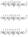
- Fig. 2A is a schematic illustration of the situation of loading in the set of rolls, in which connection each nip N 1 ...N 9 has an equally high linear load.
- a new term is also introduced in calendering technique, i.e. loading angle ⁇ , because this novel mode of loading cannot be illustrated unequivocally in traditional ways.
- said loading angle of 90° compared with conventional calenders, a significant increase in the calendering potential is obtained. This can be utilized in order to increase the running speed and the productivity.
- a high linear load and a high calendering effect a are employed in order to maximize the running speed of the calender, the productivity, and the paper quality.
- a low linear load and a low calendering effect a' are needed under different conditions and in different production stages, such as in matt calendering, in optimizing of quality, in stages of starting up and running down, and in situations of web break.
- a very low calendering effect can be achieved in each nip in the calender, as is illustrated in Fig. 2A by way of example.
- a significantly lower level of linear load is needed to produce similar properties of quality of paper. In this way, it is possible, for example, to minimize the strain applied to the soft-faced rolls in the calender, such as polymer-coated rolls, in particular in the lower part of the set of rolls.
- the loads produced by the masses of the intermediate rolls 15...22 in the set of rolls 12 and by the masses of the auxiliary devices connected with said rolls can, if necessary, also be relieved partially, or so that exclusively the pin loads are relieved, in which case, in respect of the distribution of linear load in the set of rolls, for example, a situation as shown in Fig. 2C is reached, in which the loading angle ⁇ can be adjusted, e.g., in the range 75°...80° .
- the linear loads are always increasing in the nips when moving towards a lower nip.
- the loading angle has, as a rule, been in the range 45°...55°, and the magnitude of this loading angle has been dependent on the size of the calender, i.e. mainly on the number of rolls.
- the magnitude of the loading angle ⁇ can be adjusted quite freely, and by means of this adjustability of the loading angle a considerable advantage and a remarkable improvement are achieved over earlier solutions.
- the loading angle ⁇ can be used as an active variable in fine adjustment of the differences between different faces of the paper. Adjustment of two-sidedness has a significant effect on the properties of quality of paper, and in this way, by means of the present invention, it is possible to produce paper of uniform quality reel after reel. A corresponding property has not been suggested anywhere else previously.
- the support can, of course, also be accomplished, for example, as a what is called “excessive relief", wherein the loading angle ⁇ is larger than 90°. In such a case, it is possible to reach a situation in which a lower nip always has a lower linear load than the nip placed above has. Such an embodiment has, however, not been illustrated in the figure.
- Figs. 3A, 3B and 3C illustrate the effects of different calendering parameters with different paper grades.
- the paper grade is SC paper
- Fig. 3B the grade is LWC paper
- Fig. 3C the grade is WFC paper.
- the effects of different factors on the surface properties of paper were determined by means of the results, which were obtained by changing the calendering parameters to a certain extent.
- Fig. 1 illustrates an embodiment in which the set of rolls 12 consisting of the rolls has been installed substantially vertically.
- the solution is, of course, not confined to such an embodiment only, but the set of rolls can be placed in an obliquely vertical position at least to some extent diverging from the vertical position.
- the rolls included in the set of rolls 12 one or several may be soft-coated polymer rolls and/or paper rolls, fibre rolls or other soft-faced rolls.
- the upper and the lower roll 13,14 are provided with a soft polymer coating
- the first, third, sixth, and eighth intermediate rolls 15,17,20, and 22 are hard-faced chilled rolls
- the second, fourth, fifth, and seventh intermediate rolls 16,18,19,21 are soft-coated polymer rolls.
- the number of the intermediate rolls or the relative sequence and arrangement of the soft-faced/hard rolls is, however, in no way confined to the exemplifying embodiment of Fig. 1.
- a sittlation corresponding to a normal production situation is examined, in which case the set of rolls 12 is closed in the way shown in Fig. 1 and the rolls 13...22 are under load in contact with one another.
- the automation system 30 included in the arrangement in accordance with the invention has been connected to the support cylinders 154 to measure and to control the loads of the relief cylinders.
- a uniform or different, desired distribution of linear load is formed so that in the automation system 30 the deflection lines of the intermediate rolls 15...22 and the corresponding loads of the cylinders 154 of support of the intermediate rolls are computed.
- the support cylinders 154 and the lever arms 152 are used for supporting the masses of the intermediate rolls 15...22 and the masses of the auxiliary devices connected with the intermediate rolls.
- the distribution of linear load in the machine direction is regulated by supporting the masses of the rolls and of the connected auxiliary devices completely.
- the masses of the auxiliary devices connected with the lever arms of each intermediate roll such as take-out leading rolls, possible doctors, etc., are also supported.
- the rigidities and masses of the intermediate rolls 15...22 are not equal from roll to roll. Correcting of the errors in the cross-direction profiles of the deflection lines of the rolls, arising from these differences in rigidity and mass, i.e.
- the necessary correction and regulation of the cross-direction profile of paper i.e. of thickness and/or glaze, is carried out by means of the zone cylinders in the variable-crown upper and lower roll 13,14.
- correction of the cross-direction profile can be carried out by means of regulation of the loading of the relief cylinders of the intermediate rolls.
- the method in accordance with the invention and the related computing of the distribution of the linear load in the set of rolls 12 can be applied both to a traditional mode of running of a multi-nip calender, wherein the paper web W runs through all of the nips N 1 ...N 9 , and to a modified mode of running, wherein the paper web W is passed through certain nips only.
- the automation system includes programs of maintenance of the set of rolls, distributions of linear load, roll parameters, and recipe data bases, which, together with the program of computing of the distribution of linear load, permit computing of the distributions of linear load specifically for each paper grade. Further, for maintaining the changes in the set of rolls in the calender and for monitoring the stock of rolls, there are program routines of their own.
- the distribution of linear load in the set of rolls 12 and the support forces to be passed to the support cylinders of the intermediate rolls 15...22 are computed either in the automation system 30 or in a separate computing unit directly connected with said system.
- the computing model determines the rigidity and the mass distribution of the set of rolls 12 in the calender 10 consisting of chilled rolls and polymer rolls as well as the rigidity of the nips N 1 ...N 9 between the rolls.
- the locations and masses of the outside masses connected with the set of rolls are determined, the effect of temperature on the modulus of elasticity is taken into account, the effect of the roll diameters on the original modulus of elasticity is taken into account, a possible additional linear load of the rolls and the separate effects of the centres of mass and gravity of the roll ends at the tending side and at the driving side are taken into account.
- the data employed in computing are divided into general calender-specific, nip-specific, and roll-specific data.
- the starting-value data necessary for the computing are defined in the roll data base 51, in the roll material data base 52, in the set-of-rolls mass data base 53, in the data base of geometry of the articulated linkage in the calender, i.e.
- the computing is carried out in two stages so that in the first stage the support pressures of the intermediate rolls are optimized and correction coefficients are obtained for the variable-crown upper and lower rolls. These data are utilized in the second stage of computing for optimizing the distribution of linear load of the upper roll and the lower roll.
- the way in which the calender in accordance with the invention can be made to operate in the desired way i.e. the way in which the forces that support the intermediate rolls are determined, is derived from the procedure in accordance with the invention, by whose means the ratio of the linear loads applied to the intermediate rolls, of the weight of said rolls, and of the support forces applied to said rolls is adjusted to such a level that a pre-determined state of deflection prevails in the area of the set of rolls.
- Fig. 5 illustrates a four-roll supercalender, in which the set of rolls 100 comprises a variable-crown lower roll 111, a variable-crown upper roll 112, and two intermediate rolls 113,114.
- the nip load in the nips N 101 ,N 102 ,N 103 between the rolls is produced substantially as the spring force required to produce an elastic compression of the coating on one of the rolls that form a nip.
- the force is proportional to the difference between the transitions arising in the rolls at the nip, it can be concluded directly that at each point the same load is achieved when the difference in transition at the points is the same, i.e. when the deflection lines of the rolls are of equal shape and of equal magnitude.
- the optimal relief or support of each roll is determined so that the bending load that remains on each roll mantle produces an equally high deflection on all rolls.
- the computing of the support forces of the set of rolls in the calender expressly of the whole set of rolls, is based on knowledge of the exact physical properties of the rolls, i.e. the conduct of all the rolls is known when deflecting loads of different magnitudes are applied to said rolls. It is the basis of the computing that the bearing support forces applied to each roll are determined so that the whole set of roll obtains an equally high calculatory deflection.
- the ratio of the upper nip load and the lower nip load at an individual roll so that the sum of these loads, together with the own mass of the roll, produces the same predetermined deflection in each individual roll.
- the computing can be applied to a set of rolls of any kind whatsoever in a calender, which set of rolls is placed in a substantially vertical position, in which set of rolls the upper roll is an adjustable-crown roll and the lower roll likewise an adjustable-crown roil, the axial distribution of support forces of said upper and lower roll being adjustable, and in which set of rolls there are at least two intermediate rolls between the upper roll and the lower roll. Further, it is an important requirement that all the rolls in the set of rolls are supported so that their deflection lines are downwards curved when the nips are closed.
- bearing support forces of the intermediate rolls are determined by means of computing so that the overall load applied to each intermediate roll subjects each intermediate roll substantially to such a calculatory deflection that the deflection forms of the contact faces of each roll and of the roll in contact with said roll in a nip substantially correspond to one another.
- nip forces in a calender are regulated so that the difference between the nip forces of the topmost nip and the lowest nip in the calender is determined to be at the desired level. This means, in fact, the regulation of the loading angle ⁇ that was described in relation to Figs. 2A, 2B and 2C.
- the loading angle ⁇ it is possible to use any loading angle whatsoever, and the regulation of the loading angle ⁇ is carried out by means of outside loading members through the lower roll and the upper roll.
- the variable is the support force with which the roll is supported.
- the invention provides a novel possibility of taking care of the loading and of the regulation of loading in the set of rolls in a multi-roll calender by the pair of rolls, which makes the system of regulation simpler and easier to carry into effect.
- intermediate rolls as a rule, rolls of two different types are employed, and the rigidities of these two roll types are different.
- hard-faced heatable rolls are used, on one hand, and soft-faced rolls are used, on the other hand, which soft-faced rolls can be conventional paper rolls or fibre rolls, which have been formed by fitting disks made of paper or of some other fibrous material onto the roll axle.
- the set of rolls comprises a stack of rolls placed in a substantially vertical or obliquely vertical position, wherein the rolls rest one on the other and the pin loads applied to the bearing housings of the rolls have been relieved hydraulically.
- the loading and profiling of the set of rolls is taken care of by means of variable-crown upper and lower rolls.
- the set of rolls is treated as pairs of rolls 200, which consist of a more rigid roll 202 placed as the lower half in the pair of rolls 200 and of a more flexible roll 201 placed as the upper half.
- the deflection arising from the own mass of this upper roll 201 is higher than the deflection of the lower roll 202 in the pair.
- the pairs of rolls 200 in the set of rolls are substantially similar to one another, and they have equal, common deflections depending on the masses and rigidities of the rolls 201,202.
- a force F 2 is applied, by whose means, besides relief of the pin loads, the error in the distribution of linear load between the rolls, which error arises from the different rigidities of the rolls 201,202, is compensated.
- the upper roll 201 rests with its own weight m 2 (from which the pin loads have been "cleaned") on the lower roll 202 and applies an even linear load m 2 /L to the lower roll, wherein L is the axial length of the nip N between the rolls 201,202.
- the reversing nip is a nip that is formed between two soft-faced rolls 201, and in Figs. 7A, 7B and 7C this reversing nip is denoted with N e .
- a corresponding solution has been accomplished so that the upper soft-faced roll 201 el in the reversing nip N e is arranged as a variable-crown roll.
- the deflection of said roll 201 e1 is corrected by means of the crown variation means fitted in the interior of the roll, and the mass of the roll does not load the pair of rolls 200 e1 placed underneath by means of its weight.
- a corresponding solution has been accomplished so that the upper soft-faced roll 201 e2 in the reversing nip N e has been arranged as a roll with such a rigidity that its deflection is the same as the deflection of the whole pair of rolls 200,200e 2 .
- said roll in the reversing nip does not cause any problem in the regulation of the loading.
- the computing in accordance with the invention, first the initial values of the rolls are defined, and on this basis the mathematical model corresponding to the set of rolls is formed.
- the mathematical model is formed in compliance with the number of rolls included in the set of rolls.
- the optimization computing formed for the set of rolls uses these data as the starting data.
- the nip errors of the intermediate rolls are minimized, which errors have been defined as deviations from the nominal form.
- the resilience occurring between each nip and arising from the paper and from the coatings is illustrated by a base constant, which is computed across the nip length.
- the effects of the forces to be optimized on the linear load are determined in a response data base, in which the unit response of the element of the nip of each intermediate roll is indicated in a desired number of examination points.
- the effects of invariable forces on the linear load are determined in a separate invariable-force data base, which takes into account divided masses, point masses, and nips with invariable load.
- the effects of the forces to be optimized on the restrictions and the effects of backup forces on the tension restrictions are determined.
- the assignment of optimization becomes a mathematical problem, in which the variables are limited and determined by groups of equations.
- optimal relief forces for intermediate rolls, optimal profiles of linear load and deflections of rolls are obtained.
- the optimized support forces of the intermediate rolls in the set of rolls of the calender are transferred to the support cylinders of intermediate rolls, as is illustrated, for example, in Fig. 1.
- the optimized support forces of intermediate rolls are also transferred to the program of computing of the zone pressures of the variable-crown upper and lower rolls.
- the deflection values of the intermediate rolls in the set of rolls are used for controlling and regulation of the variable-crown upper and lower rolls. From the deflection values of the intermediate rolls, by means of a separate computing program, the zone pressure corrections of the upper and the lower roll are determined, which corrections are, in each particular case, added to, or reduced from, each actual value of zone pressure.
- the distribution of linear load in the set of rolls is controlled in the method in accordance with the invention so that, by means of the user interface of the automation system, first the desired form of the distribution of linear load is determined. After this, the automation system and the included computing programs compute the above set values for the support pressures of the intermediate rolls and for the zone pressures of the variable-crown upper and lower rolls.
- the method in accordance with the invention also takes into account situations of change in the set of rolls arising from change of roll or from a new mode of running as well as any changes arising from said situations of change in the set-of-rolls data base and in the parameter data bases and in the computing. Likewise, in its roll and material data bases, the method covers and takes into account situations in which the diameters and/or material properties of chilled rolls and/or polymer rolls are changed.
- thermo roll 60 °C ...
- the range of variation of linear load can be 20 kN/m ... 550 kN/m or even higher, again depending on the running speed and on the properties of the variable-crown upper and lower rolls that produce the linear load in the supercalender.
- the invention concerns a method and an arrangement for computing and regulation of the distribution of linear load in a multi-nip calender.
- the material web (W) is passed through the nips (N1...N9) in the set of rolls (12), which set of rolls comprises a variable-crown upper roll (13), a variable-crown lower roll (14) and intermediate rolls (15...22) fitted between the upper and lower rolls (13, 14). All the rolls in the set of rolls are supported so that, when the nips (N1...N9) are closed, the bending lines of the rolls are curved downwards.
- the physical properties affecting the bending of each intermediate roll (15...22) under load such as bending rigidity, mass, shape, and material properties, are taken into account.
- the ratio of the linear loads applied to the intermediate rolls (15...22), the own weight of the rolls, and of the support forces applied to the rolls is regulated so that the set of rolls is in a state of equilibrium and in a predetermined state of deflection.
- the invention also concerns a multi-nip calender that carries out the method.
Landscapes
- Paper (AREA)
Claims (10)
- Procédé pour commander une calandre multipince qui comprend le calcul et la régulation de la distribution d'une charge linéaire, dans lequel, dans la calandre multipince, la bande de matière (W) qu'il s'agit de calandrer est enfilée entre les pinces (N1...N9) d'un jeu de rouleaux (12), lequel jeu de rouleaux est formé par un rouleau supérieur (13) à voussure variable, un rouleau inférieur (14) à voussure variable et par au moins deux rouleaux intermédiaires (15...22) munis de vérins de support (154) et interposés entre les rouleaux supérieur et inférieur (13, 14), dans lequel tous les rouleaux du jeu de rouleaux sont supportés de manière que, lorsque les pinces (N1....N9) sont fermées, les lignes de flexion des rouleaux soient incurvées vers le bas, caractérisé en ce que, dans le calcul et la régulation des charges linéaires, les propriétés physiques qui affectent la flexion de chaque rouleau intermédiaire (15...22) sous charge, telles que la rigidité à la flexion, la masse, la forme et les propriétés des matières, sont prises en compte et le rapport des charges linéaires appliquées aux rouleaux intermédiaires (15...22), du poids propre des rouleaux et des forces de support appliquées aux rouleaux, est régulé de manière que le jeu de rouleaux se trouve dans un état d'équilibre et dans un état de flexion prédéterminé,
comprenant une modélisation informatisée de tous les éléments essentiels de la calandre multipince, y compris la détermination des propriétés physiques de tous les rouleaux et la sélection du type et de la position de chaque rouleau de la calandre multipince,
la détermination de paramètres de régulation basée sur la xnodélisation informatisée,
la régulation sur la base de la modélisation informatisée, de la calandre multipince assemblée avec les types et positions des rouleaux utilisés dans la modélisation informatisée. - Procédé selon la revendication 1, caractérisé en ce que, dans le procédé, dans le jeu de rouleaux (12) de la calandre, on utilise des rouleaux intermédiaires (15...22) dont les propriétés de flexion sont différentes d'un rouleau à l'autre.
- Procédé selon la revendication 1 ou 2, caractérisé en ce que, dans le calcul, le jeu de rouleaux (12) est traité comme une seule unité.
- Procédé selon la revendication 1 ou 2, caractérisé en ce que le calcul est exécuté par une paire de rouleaux (200).
- Procédé selon une quelconque des revendications précédentes, caractérisé en ce que, dans le procédé, les rouleaux intermédiaires (15...22) du jeu de rouleaux (12) sont appuyés sur le bâti (11) de la calandre de telle manière que les rouleaux soient librement mobiles.
- Dispositif pour calculer et réguler la distribution de la charge linéaire dans une calandre multipinces conçue pour calandrer du papier ou du carton, laquelle calandre comprend un jeu de rouleaux (12) qui est monté sur le bâti de la calandre et lequel jeu de rouleaux comprend un rouleau supérieur (13) à voussure variable, un rouleau inférieur (14) à voussure variable, ainsi que plusieurs rouleaux intermédiaires (15...22) interposés entre le rouleau supérieur et le rouleau inférieur, dans lequel les moyens de suspension des rouleaux intermédiaires (15...22) sont équipés de vérins de support (154) et tous les rouleaux du jeu de rouleaux sont supportés de telle manière que, lorsque les pinces (N1...N9) sont fermées, les lignes de flexion des rouleaux soient incurvées vers le bas, caractérisé en ce que le dispositif comprend un système d'automation (30) et une unité de calcul (40) qui ont été prévus pour prendre en compte, dans le calcul et la régulation des charges linéaires, les propriétés physiques qui affectent la flexion de chaque rouleau intermédiaire (15...22) sous charge, telles que la rigidité à la flexion, la masse, la forme et les propriétés des matières, et pour réguler le rapport des charges linéaires appliquées aux rouleaux intermédiaires (15...22), du poids propre des rouleaux et des forces de support appliquées aux rouleaux de manière que le jeu de rouleaux se trouve dans un état d'équilibre et dans un état de flexion prédéterminé,
dans lequel l'unité de calcul (40) effectue la modélisation informatisée de tous les éléments essentiels de la calandre multipince, y compris la détermination des propriétés physiques de tous les rouleaux, dans lequel le type et la position de chaque rouleau dans la calandre multipince sont sélectionnés,
le système d'automation (30) régule la calandre multipince sur la base de la modélisation informatisée assemblée avec les types et les positions de rouleaux utilisés dans la modélisation informatisée. - Dispositif selon la revendication 6, caractérisé en ce que le dispositif a été agencé pour réguler le jeu de rouleaux (12) de la calandre, dans lequel les rouleaux intermédiaires (15...22) possèdent des propriétés de flexion différentes d'un rouleau à l'autre.
- Dispositif selon la revendication 6 ou 7, caractérisé en ce que le dispositif a été prévu pour traiter le jeu de rouleaux (12) comme une seule unité dans le calcul.
- Dispositif selon la revendication 6 ou 7, caractérisé en ce que le dispositif exécute le calcul par une paire de rouleaux (200).
- Calandre multipince commandée par le procédé selon une quelconque des revendications 1 à 5.
Applications Claiming Priority (3)
| Application Number | Priority Date | Filing Date | Title |
|---|---|---|---|
| US4587197P | 1997-05-07 | 1997-05-07 | |
| US45871P | 1997-05-07 | ||
| EP98920558A EP1017905B1 (fr) | 1997-05-07 | 1998-05-07 | Procede et disposition permettant de calculer et de reguler la distribution de charge lineaire dans une calandre a multiples pinces et calandre a multiples pinces |
Related Parent Applications (1)
| Application Number | Title | Priority Date | Filing Date |
|---|---|---|---|
| EP98920558A Division EP1017905B1 (fr) | 1997-05-07 | 1998-05-07 | Procede et disposition permettant de calculer et de reguler la distribution de charge lineaire dans une calandre a multiples pinces et calandre a multiples pinces |
Publications (2)
| Publication Number | Publication Date |
|---|---|
| EP1422342A1 EP1422342A1 (fr) | 2004-05-26 |
| EP1422342B1 true EP1422342B1 (fr) | 2006-01-04 |
Family
ID=32232233
Family Applications (1)
| Application Number | Title | Priority Date | Filing Date |
|---|---|---|---|
| EP04003041A Expired - Lifetime EP1422342B1 (fr) | 1997-05-07 | 1998-05-07 | Procédé et disposition permettant de calculer et de réguler la distribution de charge linéaire dans une calandre à multiples pinces et calandre à multiples pinces |
Country Status (1)
| Country | Link |
|---|---|
| EP (1) | EP1422342B1 (fr) |
Family Cites Families (2)
| Publication number | Priority date | Publication date | Assignee | Title |
|---|---|---|---|---|
| US5347446A (en) * | 1991-02-08 | 1994-09-13 | Kabushiki Kaisha Toshiba | Model predictive control apparatus |
| FI96334C (fi) * | 1993-11-24 | 1996-06-10 | Valmet Paper Machinery Inc | Menetelmä paperin tai vastaavan rainamateriaalin kalanteroinnissa ja menetelmää soveltava kalanteri |
-
1998
- 1998-05-07 EP EP04003041A patent/EP1422342B1/fr not_active Expired - Lifetime
Also Published As
| Publication number | Publication date |
|---|---|
| EP1422342A1 (fr) | 2004-05-26 |
Similar Documents
| Publication | Publication Date | Title |
|---|---|---|
| US5438920A (en) | Method for calendering a paper or an equivalent web material and a calender that makes use of the method | |
| US5029521A (en) | Calender and method of operating the same | |
| EP1017905B1 (fr) | Procede et disposition permettant de calculer et de reguler la distribution de charge lineaire dans une calandre a multiples pinces et calandre a multiples pinces | |
| EP1422342B1 (fr) | Procédé et disposition permettant de calculer et de réguler la distribution de charge linéaire dans une calandre à multiples pinces et calandre à multiples pinces | |
| EP1212484B1 (fr) | Calandre avec deux rouleaux intermediaires a patins | |
| US7407562B2 (en) | Method, system and calendar for controlling the moisture profile and/or moisture gradient of a paper web, and a web | |
| EP1745176B1 (fr) | Procede et appareil de production de papier calendre | |
| WO1999066125A1 (fr) | Methode de regulation d'un rouleau reglable par zone | |
| US6234075B1 (en) | Calender roll system | |
| EP1704280B1 (fr) | Procede et systeme pour prevenir les vibrations dans une calandre a points de pincage multiples ou dans un reseau de calandres | |
| WO2002055787A1 (fr) | Procede et appareil de controle des proprietes du papier dans une calandre |
Legal Events
| Date | Code | Title | Description |
|---|---|---|---|
| PUAI | Public reference made under article 153(3) epc to a published international application that has entered the european phase |
Free format text: ORIGINAL CODE: 0009012 |
|
| AC | Divisional application: reference to earlier application |
Ref document number: 1017905 Country of ref document: EP Kind code of ref document: P |
|
| AK | Designated contracting states |
Kind code of ref document: A1 Designated state(s): AT DE DK ES FI FR GB SE |
|
| RIN1 | Information on inventor provided before grant (corrected) |
Inventor name: HIRSALMI, ILKKA Inventor name: VILJANMAA, MIKA Inventor name: KOIVUKUNNAS, PEKKA Inventor name: MAEENPAEAE, TAPIO Inventor name: EHROLA, JUHA Inventor name: LINNONMAA, PEKKA Inventor name: KIVIOJA, PEKKA Inventor name: LEINONEN, ERKKI |
|
| 17P | Request for examination filed |
Effective date: 20041109 |
|
| AKX | Designation fees paid |
Designated state(s): AT DE DK ES FI FR GB SE |
|
| 17Q | First examination report despatched |
Effective date: 20050121 |
|
| GRAP | Despatch of communication of intention to grant a patent |
Free format text: ORIGINAL CODE: EPIDOSNIGR1 |
|
| RIN1 | Information on inventor provided before grant (corrected) |
Inventor name: VILJANMAA, MIKA Inventor name: HIRSALMI, ILKA Inventor name: KIVIOJA, PEKKA Inventor name: EHROLA, JUHA Inventor name: KOIVUKUNNAS, PEKKA Inventor name: LINNONMAA, PEKKA Inventor name: MAEENPAEAE, TAPIO Inventor name: LEINONEN, ERKKI |
|
| GRAS | Grant fee paid |
Free format text: ORIGINAL CODE: EPIDOSNIGR3 |
|
| GRAA | (expected) grant |
Free format text: ORIGINAL CODE: 0009210 |
|
| AC | Divisional application: reference to earlier application |
Ref document number: 1017905 Country of ref document: EP Kind code of ref document: P |
|
| AK | Designated contracting states |
Kind code of ref document: B1 Designated state(s): AT DE DK ES FI FR GB SE |
|
| PG25 | Lapsed in a contracting state [announced via postgrant information from national office to epo] |
Ref country code: FI Free format text: LAPSE BECAUSE OF FAILURE TO SUBMIT A TRANSLATION OF THE DESCRIPTION OR TO PAY THE FEE WITHIN THE PRESCRIBED TIME-LIMIT Effective date: 20060104 Ref country code: AT Free format text: LAPSE BECAUSE OF FAILURE TO SUBMIT A TRANSLATION OF THE DESCRIPTION OR TO PAY THE FEE WITHIN THE PRESCRIBED TIME-LIMIT Effective date: 20060104 |
|
| REG | Reference to a national code |
Ref country code: GB Ref legal event code: FG4D |
|
| REF | Corresponds to: |
Ref document number: 69833062 Country of ref document: DE Date of ref document: 20060330 Kind code of ref document: P |
|
| PG25 | Lapsed in a contracting state [announced via postgrant information from national office to epo] |
Ref country code: SE Free format text: LAPSE BECAUSE OF FAILURE TO SUBMIT A TRANSLATION OF THE DESCRIPTION OR TO PAY THE FEE WITHIN THE PRESCRIBED TIME-LIMIT Effective date: 20060404 Ref country code: DK Free format text: LAPSE BECAUSE OF FAILURE TO SUBMIT A TRANSLATION OF THE DESCRIPTION OR TO PAY THE FEE WITHIN THE PRESCRIBED TIME-LIMIT Effective date: 20060404 |
|
| PG25 | Lapsed in a contracting state [announced via postgrant information from national office to epo] |
Ref country code: ES Free format text: LAPSE BECAUSE OF FAILURE TO SUBMIT A TRANSLATION OF THE DESCRIPTION OR TO PAY THE FEE WITHIN THE PRESCRIBED TIME-LIMIT Effective date: 20060415 |
|
| PG25 | Lapsed in a contracting state [announced via postgrant information from national office to epo] |
Ref country code: GB Free format text: LAPSE BECAUSE OF NON-PAYMENT OF DUE FEES Effective date: 20060507 |
|
| PLBE | No opposition filed within time limit |
Free format text: ORIGINAL CODE: 0009261 |
|
| STAA | Information on the status of an ep patent application or granted ep patent |
Free format text: STATUS: NO OPPOSITION FILED WITHIN TIME LIMIT |
|
| 26N | No opposition filed |
Effective date: 20061005 |
|
| GBPC | Gb: european patent ceased through non-payment of renewal fee |
Effective date: 20060507 |
|
| EN | Fr: translation not filed | ||
| PG25 | Lapsed in a contracting state [announced via postgrant information from national office to epo] |
Ref country code: FR Free format text: LAPSE BECAUSE OF FAILURE TO SUBMIT A TRANSLATION OF THE DESCRIPTION OR TO PAY THE FEE WITHIN THE PRESCRIBED TIME-LIMIT Effective date: 20070223 |
|
| PG25 | Lapsed in a contracting state [announced via postgrant information from national office to epo] |
Ref country code: FR Free format text: LAPSE BECAUSE OF FAILURE TO SUBMIT A TRANSLATION OF THE DESCRIPTION OR TO PAY THE FEE WITHIN THE PRESCRIBED TIME-LIMIT Effective date: 20060104 |
|
| PGFP | Annual fee paid to national office [announced via postgrant information from national office to epo] |
Ref country code: DE Payment date: 20170523 Year of fee payment: 20 |
|
| REG | Reference to a national code |
Ref country code: DE Ref legal event code: R071 Ref document number: 69833062 Country of ref document: DE |