EP1422204A1 - Glass panel - Google Patents
Glass panel Download PDFInfo
- Publication number
- EP1422204A1 EP1422204A1 EP02743812A EP02743812A EP1422204A1 EP 1422204 A1 EP1422204 A1 EP 1422204A1 EP 02743812 A EP02743812 A EP 02743812A EP 02743812 A EP02743812 A EP 02743812A EP 1422204 A1 EP1422204 A1 EP 1422204A1
- Authority
- EP
- European Patent Office
- Prior art keywords
- glass
- gap
- glass sheets
- low melting
- sheets
- Prior art date
- Legal status (The legal status is an assumption and is not a legal conclusion. Google has not performed a legal analysis and makes no representation as to the accuracy of the status listed.)
- Granted
Links
Images




Classifications
-
- E—FIXED CONSTRUCTIONS
- E06—DOORS, WINDOWS, SHUTTERS, OR ROLLER BLINDS IN GENERAL; LADDERS
- E06B—FIXED OR MOVABLE CLOSURES FOR OPENINGS IN BUILDINGS, VEHICLES, FENCES OR LIKE ENCLOSURES IN GENERAL, e.g. DOORS, WINDOWS, BLINDS, GATES
- E06B3/00—Window sashes, door leaves, or like elements for closing wall or like openings; Layout of fixed or moving closures, e.g. windows in wall or like openings; Features of rigidly-mounted outer frames relating to the mounting of wing frames
- E06B3/66—Units comprising two or more parallel glass or like panes permanently secured together
- E06B3/6612—Evacuated glazing units
-
- C—CHEMISTRY; METALLURGY
- C03—GLASS; MINERAL OR SLAG WOOL
- C03C—CHEMICAL COMPOSITION OF GLASSES, GLAZES OR VITREOUS ENAMELS; SURFACE TREATMENT OF GLASS; SURFACE TREATMENT OF FIBRES OR FILAMENTS MADE FROM GLASS, MINERALS OR SLAGS; JOINING GLASS TO GLASS OR OTHER MATERIALS
- C03C27/00—Joining pieces of glass to pieces of other inorganic material; Joining glass to glass other than by fusing
- C03C27/06—Joining glass to glass by processes other than fusing
-
- E—FIXED CONSTRUCTIONS
- E06—DOORS, WINDOWS, SHUTTERS, OR ROLLER BLINDS IN GENERAL; LADDERS
- E06B—FIXED OR MOVABLE CLOSURES FOR OPENINGS IN BUILDINGS, VEHICLES, FENCES OR LIKE ENCLOSURES IN GENERAL, e.g. DOORS, WINDOWS, BLINDS, GATES
- E06B3/00—Window sashes, door leaves, or like elements for closing wall or like openings; Layout of fixed or moving closures, e.g. windows in wall or like openings; Features of rigidly-mounted outer frames relating to the mounting of wing frames
- E06B3/66—Units comprising two or more parallel glass or like panes permanently secured together
- E06B3/663—Elements for spacing panes
- E06B3/66309—Section members positioned at the edges of the glazing unit
- E06B3/66333—Section members positioned at the edges of the glazing unit of unusual substances, e.g. wood or other fibrous materials, glass or other transparent materials
-
- E—FIXED CONSTRUCTIONS
- E06—DOORS, WINDOWS, SHUTTERS, OR ROLLER BLINDS IN GENERAL; LADDERS
- E06B—FIXED OR MOVABLE CLOSURES FOR OPENINGS IN BUILDINGS, VEHICLES, FENCES OR LIKE ENCLOSURES IN GENERAL, e.g. DOORS, WINDOWS, BLINDS, GATES
- E06B3/00—Window sashes, door leaves, or like elements for closing wall or like openings; Layout of fixed or moving closures, e.g. windows in wall or like openings; Features of rigidly-mounted outer frames relating to the mounting of wing frames
- E06B3/66—Units comprising two or more parallel glass or like panes permanently secured together
- E06B3/677—Evacuating or filling the gap between the panes ; Equilibration of inside and outside pressure; Preventing condensation in the gap between the panes; Cleaning the gap between the panes
- E06B3/6775—Evacuating or filling the gap during assembly
-
- Y—GENERAL TAGGING OF NEW TECHNOLOGICAL DEVELOPMENTS; GENERAL TAGGING OF CROSS-SECTIONAL TECHNOLOGIES SPANNING OVER SEVERAL SECTIONS OF THE IPC; TECHNICAL SUBJECTS COVERED BY FORMER USPC CROSS-REFERENCE ART COLLECTIONS [XRACs] AND DIGESTS
- Y02—TECHNOLOGIES OR APPLICATIONS FOR MITIGATION OR ADAPTATION AGAINST CLIMATE CHANGE
- Y02A—TECHNOLOGIES FOR ADAPTATION TO CLIMATE CHANGE
- Y02A30/00—Adapting or protecting infrastructure or their operation
- Y02A30/24—Structural elements or technologies for improving thermal insulation
- Y02A30/249—Glazing, e.g. vacuum glazing
-
- Y—GENERAL TAGGING OF NEW TECHNOLOGICAL DEVELOPMENTS; GENERAL TAGGING OF CROSS-SECTIONAL TECHNOLOGIES SPANNING OVER SEVERAL SECTIONS OF THE IPC; TECHNICAL SUBJECTS COVERED BY FORMER USPC CROSS-REFERENCE ART COLLECTIONS [XRACs] AND DIGESTS
- Y02—TECHNOLOGIES OR APPLICATIONS FOR MITIGATION OR ADAPTATION AGAINST CLIMATE CHANGE
- Y02B—CLIMATE CHANGE MITIGATION TECHNOLOGIES RELATED TO BUILDINGS, e.g. HOUSING, HOUSE APPLIANCES OR RELATED END-USER APPLICATIONS
- Y02B80/00—Architectural or constructional elements improving the thermal performance of buildings
- Y02B80/22—Glazing, e.g. vaccum glazing
-
- Y—GENERAL TAGGING OF NEW TECHNOLOGICAL DEVELOPMENTS; GENERAL TAGGING OF CROSS-SECTIONAL TECHNOLOGIES SPANNING OVER SEVERAL SECTIONS OF THE IPC; TECHNICAL SUBJECTS COVERED BY FORMER USPC CROSS-REFERENCE ART COLLECTIONS [XRACs] AND DIGESTS
- Y10—TECHNICAL SUBJECTS COVERED BY FORMER USPC
- Y10T—TECHNICAL SUBJECTS COVERED BY FORMER US CLASSIFICATION
- Y10T428/00—Stock material or miscellaneous articles
- Y10T428/24—Structurally defined web or sheet [e.g., overall dimension, etc.]
- Y10T428/24777—Edge feature
Definitions
- the present invention relates to a glass panel including a pair of glass sheets disposed in opposition to each other with a gap formed therebetween, peripheral edges of the two glass sheets being bonded with low melting glass for sealing the gap.
- the low melting glass is often used for sealing the gap of such glass panel as above because it has superior adhesive property to e.g. metal solder.
- the low melting glass in the form of paste would be applied to the peripheral edges of the two glass sheets and heated to 480°C or higher, thereby to render the low melting glass into melted state. Then, it would be cooled to the normal temperature for solidification, whereby the peripheral edges of the glass sheets were bonded for sealing the gap.
- the low melting glass has good adhesive property for the glass sheets
- the glass under its melted state also has good wettability to the glass sheets.
- an adjacent face 4b of the low melting glass 4 adjacent the gap V is formed as a concave face with its center portion between the glass sheets 1, 2 extending away from the gap V.
- the glass would be cooled and hardened directly under such condition.
- the adjacent face 4b of the low melting glass 4 adjacent the gap V is formed as a concave face with its center portion between the glass sheets 1, 2 extending away from the gap V.
- the conventional glass panel has a shortcoming in the strength of the low melting glass used for bonding and sealing the peripheral edges of the two glass sheets. This shortcoming would appear especially conspicuously with a vacuum double glazing with the gap between the opposed glass sheets being maintained under a depressurized state.
- the present invention addresses to such shortcoming of the convention and its object is to provide a glass panel which even when constructed as a vacuum double glazing, can effectively prevent damage in the low melting glass portion thereof by improving the strength of the low melting glass used at the peripheral edges of the two glass sheets.
- the characterizing features of a glass panel relating to the present invention are as follows.
- a glass panel relating to claim 1, as illustrated in Fig. 3 and Figs. 5-7, includes a pair of glass sheets 1, 2 disposed in opposition to each other via a gap V therebetween, peripheral edges of the two glass sheets 1, 2 being bonded with low melting glass 4 for sealing the gap V, wherein in a cross section substantially normal to faces of the two glass sheets, 1,2, an adjacent face 4a of the low melting glass 4 adjacent the gap V has a center portion thereof between the two glass sheets 1, 2 bulging toward the gap V.
- the adjacent face of the low melting glass adjacent the gap has a center portion thereof between the two glass sheets bulging toward the gap.
- the adjacent face 4a is formed as a curved face bulging toward the gap V.
- the adjacent face is formed as a curved face bulging toward the gap, compared with a construction wherein the adjacent face is formed as a face bulging toward the gap at an acute angle, the above construction can avoid stress concentration even more reliably. Hence, the strength of the low melting glass at the peripheral edges of the glass sheets can be further improved.
- spacers 3 are provided in the gap V between the pair of glass sheets 1, 2, the gap V being sealed under a depressurized state.
- the atmospheric pressure is constantly applied to the faces of its glass sheets, thus causing problem in the strength of the low melting glass.
- the strength of the low melting glass can be improved. As a result, it is possible to provide a glass panel which has the superior thermal insulation performance and also superior strength.
- This double glazing P as shown in Fig. 1, includes a pair of glass sheets 1,2 and a number of spacers 3 interposed between faces of the two glass sheets 1,2, so that the two glass sheets 1, 2 are disposed in opposition to each other with forming a gap V therebetween. Peripheral edges of the two glass sheets 1,2 are bonded together with a low melting glass 4 which has a lower melting point than the two glass sheets 1, 2 and which also has a low gas-permeability, and the gap V between the glass sheets 1, 2 is sealed under a depressurized state.
- a low melting glass 4 which has a lower melting point than the two glass sheets 1, 2 and which also has a low gas-permeability
- Each of the two glass sheets 1, 2 employs a transparent float glass sheet having a thickness ranging 2.65 mm to 3.2 mm. And, the gap V between the glass sheets 1, 2 is depressurized to 1.33 Pa (1.0 x 10- 2 Torr) or lower.
- one glass sheet 1 defines an evacuation hole 5 consisting of a large-diameter hole 5a having an approximate diameter of 3 mm and a small-diameter hole 5b having an approximate diameter of 2 mm; and a glass tube 6 is inserted into the large-diameter hole 5a. Then, this glass tube 6 is fixedly bonded to the glass sheet 1 with a low melting glass 7 having a lower melting point than the glass tube 6 and the glass sheet 1 and the leading free end of the glass tube 6 is sealed by means of fusing and the entire tube is covered with a cap 8.
- the spacer 3 preferably has a cylindrical shape. And, in order to be able to withstand the atmospheric pressure acting on the two glass sheets 1, 2, the spacer is made of a material having a compression strength of: 4.9 x 10 8 Pa (5 x 10 3 kgf/cm 2 ) or higher, such as stainless steel (SUS 304) or Inconel 718.
- this spacer when the spacer 3 has such cylindrical shape, this spacer will have dimensions of: approximate diameter of 0.3 to 1.0 mm and approximate height of 0.15 to 1.0 mm. Further, the inter-distance between adjacent spacers 3 is set to about 20 mm.
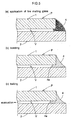
- the glass sheet 2 not defining the evacuation hole 5 is supported substantially horizontal and on the top face of its peripheral edge, the low melting glass 4 in the form of paste is applied and also the many spacers 3 are disposed with the predetermined inter-distance therebetween. Then, as shown in Fig. 5 (a), the other glass sheet 1 is placed over them from the above.
- the lower glass sheet 2 may have a slightly larger area so that its peripheral edge may slightly project from the peripheral edge of the upper glass sheet 1. This will be advantageous for e.g. the application of the low melting glass 4.
- the glass tube 6 is inserted into the evacuation hole 5 of the upper glass sheet 1.
- this glass tube 6 can be inserted into only the large-diameter hole 5a of the evacuation hole 5 and has a length greater than that of the large-diameter hole 5a, the upper portion of the glass tube 6 will project from the glass sheet 1.
- low melting glass 7 having a doughnut-like shape is fitted and an evacuation sealing device 9 is placed over this assembly.
- the evacuation sealing device 9 includes an evacuation cup 10 having a cylindrical shape with a bottom and an electric heater 11 disposed within the evacuation cup 10.
- the device 9 further includes such components as an evacuation flexible pipe 12 communicated with the inner space of the evacuation cup 10 and an O-ring 13 for sealing relative to the top face of the glass sheet 1.
- the two glass sheets 1, 2 are charged into and housed under substantially horizontal posture in a heating furnace 14.
- the low melting glass 4 is molten and with the low melting glass 4 under this molten state, the peripheral edges of the opposed glass sheets 1, 2 are bonded together thereby to seal the gap V. This completes the bonding operation.
- the temperature inside the heating furnace 14 is elevated to 480°C or higher for melting the low melting glass 4.
- the molten low melting glass 4 has good wettability to the two glass sheets 1, 2, as shown in Fig. 5 (b), in a cross section substantially normal to the faces of the two glass sheets 1, 2, an adjacent face 4 of the low melting glass adjacent the gap V will be formed concave relative to the gap V and with the melting of this low melting glass 4, the low melting glass 7 about the glass tube 6 too is melted to flow into the gap between the large-diameter hole 5a and the glass tube 6.
- the inside of the evacuation cup 10 is depressurized and also the inside of the vap V is depressurized to 1.33 Pa or lower via the glass tube 6 and the small-diameter hole 5b.
- the low melting glass 4 is under the softened state having the viscosity of 10 10 Pascal/sec. (Pa ⁇ s). Hence, in association of the depressurization of the gap V, its adjacent face 4a will be formed into a curved face bulging toward the gap V, as shown in Fig. 3 or Fig. 5 (c).
- the leading end of the glass tube 6 is locally heated to about 1000°C, so that the opening of this leading end of the glass tube 6 is sealed, as shown in Fig. 4
- the cap 8 is bonded to the glass sheet 1, thereby to complete the vacuum double glazing P.
- the adjacent face 4a of the low melting glass 4 is formed as the curved face bulging toward the gap V. Therefore, even when the two glass sheets 1, 2 are subjected to a force which tends to displace the sheets closer to each other, as indicated by arrows in Fig. 7, its stress will be dissipated toward the bulging portion, so that substantially no stress concentration will occur. Hence, in comparison with the conventional construction shown in Fig. 8, the strength of the low melting glass 4 can be improved significantly.
- test samples of this invention's glass panel and the conventional glass panel were made to conduct a comparison experiment therebetween. The results of this experiment will be described next.
- test glass panels were made by the following processes (a) and (b).
- test sample of the invention was manufactured by the above-described steps (a) through (e), whereas the test sample of the convention was manufactured by the above steps (a), (b) and (f). Then, on the sealed portions of these two kinds of test samples, their shapes were observed.
- a testing form panel 16 allowing depressurization of its inside 15 was prepared and on this form panel 16, the two kinds of test samples were mounted. And, as a simulation of a wind load, the inside 15 of the form panel 16 was progressively depressurized by means of an evacuation pump to achieve a pressure difference of 0 to -20 kPa relative to the atmospheric pressure. In the course of this, the destruction condition was monitored and the pressure of the inside 15 at the very moment of start of destruction was determined.
- the load due to the atmospheric pressure is applied substantially uniformly to the top side of the test sample, so that the test sample will be warped in an arcuate form with its lower side being formed as a convex face downwards.
- the stress occurs not only on the faces of the glass sheets, but also on the interfaces between the sealed portion and the glass sheet at the end portions of the two glass sheets.
- the sealed portion at the ends of the two glass sheets has structural weakness, the destruction will start earlier at the vicinity of the sealed portion than on the glass faces.
- the sealed portion at the ends is strong, the destruction will start earlier at the glass faces. Therefore, the above-described results establish that the glass panel of the invention is superior in strength to the conventional glass panel.
- the glass panel can be used in various applications, such as a window pane for a building or a vehicle (automobile, railway car, boat) or instruments such as a plasma display or a door or a wall of various machines such as a refrigerator, a thermal insulator, etc.
- the glass sheets 1, 2 constituting the glass panel P are not limited to the float glass sheets described in the foregoing embodiment.
- it may be a figured glass, frosted glass provided with the function of diffusing light through a surface treatment, mesh glass, a wired glass, a reinforced glass, double-reinforced glass, low reflection glass, high transmission glass sheet, ceramic printed glass, special glass provided with a function of heat absorption, UV absorption, etc. or any combination of these.
- the composition of the glass may be soda silica glass, soda lime silica glass, borosilicate glass, aluminosilicate glass, various kinds of crystallized glass.
- the thickness of the glass sheets 1, 2 too may be freely selected as appropriate.
- the material of the spacer 3 is not limited to the stainless steel or Inconel. Instead, it may be a metal such as iron, copper, aluminum, tungsten, nickel, chromium, titanium, an alloy such as carbon steel, chromium steel, nickel steel, nickel-chrome steel, manganese steel, chromium-manganese steel, chrome molybdenum steel, silicon steel, brass, solder, duralumin, etc, ceramics, or glass. In short, any material may be used-if-it is hardly deformed by an external force. And, its shape too is-not limited to the cylindrical shape, but may be a variety of shapes such as angular column-like shape or spherical shape, etc.
- the low melting glass 7 for fusing the glass tube 6 it is also possible to employ a crystalline low melting glass which completes its crystallization at a high temperature range or a non-crystalline low melting glass.
- the low melting glass 4 for bonding and sealing the peripheral edges of the two glass sheets 1, 2 it is possible to employ either crystalline or non-crystalline low melting glass.
- the glass panel of the present invention can be used in various applications, such as a window pane for a building or a vehicle (automobile, railway car, boat) or instruments such as a plasma display or a door or a wall of various machines such as a refrigerator, a thermal insulator, etc.
Landscapes
- Engineering & Computer Science (AREA)
- Civil Engineering (AREA)
- Structural Engineering (AREA)
- Chemical & Material Sciences (AREA)
- Ceramic Engineering (AREA)
- Life Sciences & Earth Sciences (AREA)
- Chemical Kinetics & Catalysis (AREA)
- General Chemical & Material Sciences (AREA)
- Geochemistry & Mineralogy (AREA)
- Materials Engineering (AREA)
- Organic Chemistry (AREA)
- Joining Of Glass To Other Materials (AREA)
- Securing Of Glass Panes Or The Like (AREA)
Abstract
Description
Claims (3)
- A glass panel comprising: a pair of glass sheets (1), (2) disposed in opposition to each other via a gap (V) therebetween, peripheral edges of the two glass sheets (1), (2) being bonded with low melting glass (4) for sealing the gap (V);
wherein in a cross section substantially normal to faces of the two glass sheets, (1), (2), an adjacent face (4a) of the low melting glass (4) adjacent the gap (V) has a center portion thereof between the two glass sheets (1), (2) bulging toward the gap (V). - The glass panel according to claim 1, wherein the adjacent face (4a) is formed as a curved face bulging toward the gap (V).
- The glass panel according to claim 1 or 2; wherein spacers are provided in the gap (V) between the pair of glass sheets (1), (2), the gap (V) being sealed under a depressurized state.
Applications Claiming Priority (3)
| Application Number | Priority Date | Filing Date | Title |
|---|---|---|---|
| JP2001204547 | 2001-07-05 | ||
| JP2001204547A JP4203235B2 (en) | 2001-07-05 | 2001-07-05 | Glass panel |
| PCT/JP2002/006760 WO2003004430A1 (en) | 2001-07-05 | 2002-07-03 | Glass panel |
Publications (3)
| Publication Number | Publication Date |
|---|---|
| EP1422204A1 true EP1422204A1 (en) | 2004-05-26 |
| EP1422204A4 EP1422204A4 (en) | 2005-08-24 |
| EP1422204B1 EP1422204B1 (en) | 2012-06-27 |
Family
ID=19040996
Family Applications (1)
| Application Number | Title | Priority Date | Filing Date |
|---|---|---|---|
| EP02743812A Expired - Lifetime EP1422204B1 (en) | 2001-07-05 | 2002-07-03 | Glass panel |
Country Status (6)
| Country | Link |
|---|---|
| US (1) | US7244480B2 (en) |
| EP (1) | EP1422204B1 (en) |
| JP (1) | JP4203235B2 (en) |
| AU (1) | AU2002363814B2 (en) |
| CA (1) | CA2449207A1 (en) |
| WO (1) | WO2003004430A1 (en) |
Cited By (10)
| Publication number | Priority date | Publication date | Assignee | Title |
|---|---|---|---|---|
| EP1529921A2 (en) | 2003-10-27 | 2005-05-11 | Werner Wüthrich | Heat transmission reducing closure element |
| GB2435896A (en) * | 2006-02-28 | 2007-09-12 | Alexander Simpson | Double glazed units comprising inner and outer panes having individual panes directly bonded together |
| WO2018150016A1 (en) | 2017-02-17 | 2018-08-23 | Vkr Holding A/S | Top frit heat treatment |
| EP3467143A1 (en) | 2017-10-06 | 2019-04-10 | VKR Holding A/S | Vacuum insulated glazing unit |
| US10358861B2 (en) | 2017-02-17 | 2019-07-23 | Vkr Holding A/S | Vacuum insulated glazing unit |
| US10533366B2 (en) | 2018-02-14 | 2020-01-14 | Vkr Holding A/S | Compressible pillar for a vacuum insulated glazing unit |
| US10731403B2 (en) | 2017-10-06 | 2020-08-04 | Vkr Holding A/S | Vacuum insulated glazing unit |
| US11060342B2 (en) | 2017-02-17 | 2021-07-13 | Vkr Holding A/S | Vacuum insulated glazing unit |
| US11771831B2 (en) | 2016-10-11 | 2023-10-03 | Phillips-Medisize A/S | Auto injector with automated reconstitution |
| EP3906351B1 (en) * | 2019-01-02 | 2024-07-10 | VKR Holding A/S | Sealant in a vacuum insulated glazing unit |
Families Citing this family (31)
| Publication number | Priority date | Publication date | Assignee | Title |
|---|---|---|---|---|
| WO2008004709A1 (en) * | 2006-07-06 | 2008-01-10 | Nippon Sheet Glass Company, Limited | Evacuated glass panel and manufacturing method thereof |
| DE102007030031B3 (en) * | 2007-06-29 | 2009-02-26 | Futech Gmbh | Heat-insulating glazing element and method for its production |
| US8512829B2 (en) * | 2007-12-14 | 2013-08-20 | Guardian Industries Corp. | Metal-inclusive edge seal for vacuum insulating glass unit, and/or method of making the same |
| US8137494B2 (en) | 2007-12-14 | 2012-03-20 | Guardian Industries Corp. | Vacuum insulating glass unit with large pump-out port, and/or method of making the same |
| US8500933B2 (en) * | 2007-12-14 | 2013-08-06 | Guardian Industries Corp. | Localized heating of edge seals for a vacuum insulating glass unit, and/or unitized oven for accomplishing the same |
| US8460493B2 (en) | 2007-12-14 | 2013-06-11 | Guardian Industries Corp. | Evacuation and port sealing techniques for vacuum insulating glass units, and/or vacuum oven for accomplishing the same |
| US8506738B2 (en) | 2007-12-17 | 2013-08-13 | Guardian Industries Corp. | Localized heating via an infrared heat source array of edge seals for a vacuum insulating glass unit, and/or unitized oven with infrared heat source array for accomplishing the same |
| US8227055B2 (en) | 2009-05-01 | 2012-07-24 | Guardian Industries Corp. | Vacuum insulating glass unit including infrared meltable glass frit, and/or method of making the same |
| US8202587B2 (en) * | 2009-05-01 | 2012-06-19 | Guardian Industries Corp. | Edge profiles for vacuum insulated glass (VIG) units, and/or VIG unit including the same |
| US8733128B2 (en) | 2011-02-22 | 2014-05-27 | Guardian Industries Corp. | Materials and/or method of making vacuum insulating glass units including the same |
| US9309146B2 (en) | 2011-02-22 | 2016-04-12 | Guardian Industries Corp. | Vanadium-based frit materials, binders, and/or solvents and methods of making the same |
| US9822580B2 (en) | 2011-02-22 | 2017-11-21 | Guardian Glass, LLC | Localized heating techniques incorporating tunable infrared element(s) for vacuum insulating glass units, and/or apparatuses for same |
| US8802203B2 (en) | 2011-02-22 | 2014-08-12 | Guardian Industries Corp. | Vanadium-based frit materials, and/or methods of making the same |
| US9359247B2 (en) | 2011-02-22 | 2016-06-07 | Guardian Industries Corp. | Coefficient of thermal expansion filler for vanadium-based frit materials and/or methods of making and/or using the same |
| US9458052B2 (en) | 2011-02-22 | 2016-10-04 | Guardian Industries Corp. | Coefficient of thermal expansion filler for vanadium-based frit materials and/or methods of making and/or using the same |
| US9290408B2 (en) | 2011-02-22 | 2016-03-22 | Guardian Industries Corp. | Vanadium-based frit materials, and/or methods of making the same |
| RU2472008C1 (en) * | 2011-05-05 | 2013-01-10 | Государственное образовательное учреждение высшего профессионального образования "Елецкий государственный университет им. И.А. Бунина" | Gas-distributing mechanism of internal combustion engine |
| TWI472499B (en) * | 2012-02-10 | 2015-02-11 | Teco Nanotech Co Ltd | Exhausted and sintered package and sealing method for vacuum-insulated glasses |
| CN102748714B (en) * | 2012-06-28 | 2013-12-11 | 深圳市华星光电技术有限公司 | Fluorescent powder substrate manufacturing method and liquid crystal module using fluorescent powder substrate |
| US9675231B2 (en) | 2013-12-19 | 2017-06-13 | Whirlpool Corporation | Door assembly for a dishwasher |
| US9988302B2 (en) | 2014-02-04 | 2018-06-05 | Guardian Glass, LLC | Frits for use in vacuum insulating glass (VIG) units, and/or associated methods |
| US9593527B2 (en) | 2014-02-04 | 2017-03-14 | Guardian Industries Corp. | Vacuum insulating glass (VIG) unit with lead-free dual-frit edge seals and/or methods of making the same |
| US10165870B2 (en) | 2014-02-11 | 2019-01-01 | Anthony, Inc. | Display case door assembly with vacuum panel |
| US9498072B2 (en) | 2014-02-11 | 2016-11-22 | Anthony, Inc. | Display case door assembly with tempered glass vacuum panel |
| KR101578073B1 (en) * | 2014-07-14 | 2015-12-16 | 코닝정밀소재 주식회사 | Method for hermetic sealing and hermetically sealed substrate package |
| US10253550B1 (en) | 2015-10-30 | 2019-04-09 | Corning Incorporated | Vacuum insulated glass units and methodology for manufacturing the same |
| JP6610228B2 (en) * | 2015-12-10 | 2019-11-27 | 日本電気硝子株式会社 | Glass tube forming sleeve |
| US9687087B1 (en) | 2016-06-16 | 2017-06-27 | Anthony, Inc. | Display case door assembly with vacuum panel and lighting features |
| BR112020023072A2 (en) | 2018-05-11 | 2021-02-02 | Temple University-Of The Commonwealth System Of Higher Education | new functionalized lactams as modulators of the 5-hydroxytryptamine 7 receptor and their method of use |
| US20210131169A1 (en) * | 2018-05-31 | 2021-05-06 | Panasonic Intellectual Property Management Co., Ltd. | Glass panel unit manufacturing method |
| JP7026330B2 (en) * | 2018-06-26 | 2022-02-28 | パナソニックIpマネジメント株式会社 | Manufacturing method of glass panel unit |
Family Cites Families (16)
| Publication number | Priority date | Publication date | Assignee | Title |
|---|---|---|---|---|
| US2032003A (en) * | 1934-11-03 | 1936-02-25 | Pittsburgh Plate Glass Co | Method of making a double glazed unit |
| US2193393A (en) * | 1937-10-05 | 1940-03-12 | Danner Edward | Heat insulating glass |
| FR921946A (en) * | 1946-02-09 | 1947-05-22 | Manufacturing process of insulating panels or tiles | |
| JPS4747571B1 (en) * | 1968-10-08 | 1972-11-30 | ||
| CH622358A5 (en) * | 1977-09-06 | 1981-03-31 | Bbc Brown Boveri & Cie | |
| JPS5536828A (en) * | 1978-09-08 | 1980-03-14 | Hitachi Ltd | Production of liquid crystal display element |
| US4748137A (en) * | 1987-05-20 | 1988-05-31 | Corning Glass Works | Low temperature melting frits |
| EP0645516B1 (en) * | 1993-09-27 | 2002-01-23 | Saint-Gobain Glass France | Insulating glazing and a vacuum generating method therefor |
| MX9605168A (en) * | 1995-11-02 | 1997-08-30 | Guardian Industries | Neutral, high performance, durable low-e glass coating system, insulating glass units made therefrom, and methods of making same. |
| WO1999057074A1 (en) * | 1998-05-01 | 1999-11-11 | Nippon Sheet Glass Co., Ltd. | Glass panel, method of manufacturing glass panel, and spacer used for glass panel |
| JP4503856B2 (en) * | 1999-03-25 | 2010-07-14 | 日本板硝子株式会社 | Glass panel and manufacturing method thereof |
| US6336984B1 (en) * | 1999-09-24 | 2002-01-08 | Guardian Industries Corporation | Vacuum IG window unit with peripheral seal at least partially diffused at temper |
| US6399169B1 (en) * | 1999-07-07 | 2002-06-04 | Guardian Industries Corp. | Vacuum IG window unit with dual peripheral seal |
| JP2002167249A (en) * | 2000-11-30 | 2002-06-11 | Nippon Sheet Glass Co Ltd | Glass panel |
| US20030108692A1 (en) * | 2000-11-30 | 2003-06-12 | Shinjiro Domi | Glass panel and method of manufacturing the glass panel |
| CA2431643C (en) | 2001-06-22 | 2010-08-24 | The University Of Sydney | Method of manufacturing a glass panel |
-
2001
- 2001-07-05 JP JP2001204547A patent/JP4203235B2/en not_active Expired - Lifetime
-
2002
- 2002-07-03 AU AU2002363814A patent/AU2002363814B2/en not_active Expired
- 2002-07-03 EP EP02743812A patent/EP1422204B1/en not_active Expired - Lifetime
- 2002-07-03 WO PCT/JP2002/006760 patent/WO2003004430A1/en not_active Ceased
- 2002-07-03 CA CA002449207A patent/CA2449207A1/en not_active Abandoned
-
2003
- 2003-12-30 US US10/749,978 patent/US7244480B2/en not_active Expired - Lifetime
Cited By (15)
| Publication number | Priority date | Publication date | Assignee | Title |
|---|---|---|---|---|
| EP1529921A2 (en) | 2003-10-27 | 2005-05-11 | Werner Wüthrich | Heat transmission reducing closure element |
| GB2435896A (en) * | 2006-02-28 | 2007-09-12 | Alexander Simpson | Double glazed units comprising inner and outer panes having individual panes directly bonded together |
| GB2435896B (en) * | 2006-02-28 | 2008-09-17 | Alexander Simpson | Double glazed units |
| US11771831B2 (en) | 2016-10-11 | 2023-10-03 | Phillips-Medisize A/S | Auto injector with automated reconstitution |
| US10358861B2 (en) | 2017-02-17 | 2019-07-23 | Vkr Holding A/S | Vacuum insulated glazing unit |
| US11060342B2 (en) | 2017-02-17 | 2021-07-13 | Vkr Holding A/S | Vacuum insulated glazing unit |
| WO2018150016A1 (en) | 2017-02-17 | 2018-08-23 | Vkr Holding A/S | Top frit heat treatment |
| US12065872B2 (en) | 2017-02-17 | 2024-08-20 | Vkr Holding A/S | Top frit heat treatment |
| EP3467144A1 (en) | 2017-10-06 | 2019-04-10 | VKR Holding A/S | Vacuum insulated glazing unit |
| EP3467143A1 (en) | 2017-10-06 | 2019-04-10 | VKR Holding A/S | Vacuum insulated glazing unit |
| US10731403B2 (en) | 2017-10-06 | 2020-08-04 | Vkr Holding A/S | Vacuum insulated glazing unit |
| US10533366B2 (en) | 2018-02-14 | 2020-01-14 | Vkr Holding A/S | Compressible pillar for a vacuum insulated glazing unit |
| US11162298B2 (en) | 2018-02-14 | 2021-11-02 | Vkr Holding A/S | Compressible pillar for a vacuum insulated glazing unit |
| US11702882B2 (en) | 2018-02-14 | 2023-07-18 | Vkr Holding A/S | Compressible pillar for a vacuum insulated glazing unit |
| EP3906351B1 (en) * | 2019-01-02 | 2024-07-10 | VKR Holding A/S | Sealant in a vacuum insulated glazing unit |
Also Published As
| Publication number | Publication date |
|---|---|
| CA2449207A1 (en) | 2003-01-16 |
| WO2003004430A8 (en) | 2003-03-27 |
| EP1422204B1 (en) | 2012-06-27 |
| AU2002363814B2 (en) | 2008-01-03 |
| US20040157010A1 (en) | 2004-08-12 |
| EP1422204A4 (en) | 2005-08-24 |
| US7244480B2 (en) | 2007-07-17 |
| JP4203235B2 (en) | 2008-12-24 |
| WO2003004430A1 (en) | 2003-01-16 |
| AU2002363814A1 (en) | 2003-01-21 |
| JP2003020259A (en) | 2003-01-24 |
Similar Documents
| Publication | Publication Date | Title |
|---|---|---|
| US7244480B2 (en) | Glass panel | |
| CN1277778C (en) | Method for producing glass panel and glass panel produced by the method | |
| US7115308B2 (en) | Glass panel and method of manufacturing the glass panel | |
| US6503583B2 (en) | Vacuum IG window unit with fiber inclusive edge seal | |
| WO2001023700A1 (en) | Vacuum insulation glass window unit with peripheral | |
| US6663923B2 (en) | Glass panel | |
| US20020064610A1 (en) | Glass panel | |
| KR100461089B1 (en) | Glass Panel | |
| KR20200073287A (en) | Glass panel | |
| US20020078711A1 (en) | Glass panel and its method of manufacturing | |
| CA2431643C (en) | Method of manufacturing a glass panel | |
| WO2003035567A1 (en) | Vacuum double glazing | |
| WO2000041980A1 (en) | Glass panel | |
| JP2002255593A (en) | Method for manufacturing low pressure double glazing | |
| WO2000041979A1 (en) | Glass panel | |
| JP2001180986A (en) | Low pressure double glazing | |
| CN111295363B (en) | Method for manufacturing glass panel and glass panel | |
| JP2002128543A (en) | Glass panel |
Legal Events
| Date | Code | Title | Description |
|---|---|---|---|
| PUAI | Public reference made under article 153(3) epc to a published international application that has entered the european phase |
Free format text: ORIGINAL CODE: 0009012 |
|
| 17P | Request for examination filed |
Effective date: 20031129 |
|
| AK | Designated contracting states |
Kind code of ref document: A1 Designated state(s): AT BE BG CH CY CZ DE DK EE ES FI FR GB GR IE IT LI LU MC NL PT SE SK TR |
|
| RIN1 | Information on inventor provided before grant (corrected) |
Inventor name: NG, NELSON Inventor name: MINAAI, TETSUO,NIPPON SHEET GLASS CO., LTD. Inventor name: COLLINS, RICHARD EDWARD |
|
| A4 | Supplementary search report drawn up and despatched |
Effective date: 20050711 |
|
| RIC1 | Information provided on ipc code assigned before grant |
Ipc: 7C 03C 27/06 A Ipc: 7E 06B 3/663 B |
|
| 17Q | First examination report despatched |
Effective date: 20081110 |
|
| REG | Reference to a national code |
Ref country code: DE Ref legal event code: R079 Ref document number: 60243222 Country of ref document: DE Free format text: PREVIOUS MAIN CLASS: C03C0027060000 Ipc: E06B0003677000 |
|
| RIC1 | Information provided on ipc code assigned before grant |
Ipc: E06B 3/677 20060101AFI20111122BHEP Ipc: E06B 3/663 20060101ALI20111122BHEP Ipc: C03C 27/06 20060101ALI20111122BHEP |
|
| GRAP | Despatch of communication of intention to grant a patent |
Free format text: ORIGINAL CODE: EPIDOSNIGR1 |
|
| GRAS | Grant fee paid |
Free format text: ORIGINAL CODE: EPIDOSNIGR3 |
|
| GRAA | (expected) grant |
Free format text: ORIGINAL CODE: 0009210 |
|
| AK | Designated contracting states |
Kind code of ref document: B1 Designated state(s): DE FR GB |
|
| REG | Reference to a national code |
Ref country code: GB Ref legal event code: FG4D |
|
| REG | Reference to a national code |
Ref country code: DE Ref legal event code: R096 Ref document number: 60243222 Country of ref document: DE Effective date: 20120823 |
|
| PLBE | No opposition filed within time limit |
Free format text: ORIGINAL CODE: 0009261 |
|
| STAA | Information on the status of an ep patent application or granted ep patent |
Free format text: STATUS: NO OPPOSITION FILED WITHIN TIME LIMIT |
|
| 26N | No opposition filed |
Effective date: 20130328 |
|
| REG | Reference to a national code |
Ref country code: DE Ref legal event code: R097 Ref document number: 60243222 Country of ref document: DE Effective date: 20130328 |
|
| REG | Reference to a national code |
Ref country code: FR Ref legal event code: PLFP Year of fee payment: 15 |
|
| REG | Reference to a national code |
Ref country code: FR Ref legal event code: PLFP Year of fee payment: 16 |
|
| REG | Reference to a national code |
Ref country code: FR Ref legal event code: PLFP Year of fee payment: 17 |
|
| PGFP | Annual fee paid to national office [announced via postgrant information from national office to epo] |
Ref country code: FR Payment date: 20210611 Year of fee payment: 20 |
|
| PGFP | Annual fee paid to national office [announced via postgrant information from national office to epo] |
Ref country code: GB Payment date: 20210609 Year of fee payment: 20 |
|
| PGFP | Annual fee paid to national office [announced via postgrant information from national office to epo] |
Ref country code: DE Payment date: 20210608 Year of fee payment: 20 |
|
| REG | Reference to a national code |
Ref country code: DE Ref legal event code: R071 Ref document number: 60243222 Country of ref document: DE |
|
| REG | Reference to a national code |
Ref country code: GB Ref legal event code: PE20 Expiry date: 20220702 |
|
| PG25 | Lapsed in a contracting state [announced via postgrant information from national office to epo] |
Ref country code: GB Free format text: LAPSE BECAUSE OF EXPIRATION OF PROTECTION Effective date: 20220702 |