EP1422128A2 - Gravity compensation method in a human assist system and a human assist system with gravity compensation control - Google Patents
Gravity compensation method in a human assist system and a human assist system with gravity compensation control Download PDFInfo
- Publication number
- EP1422128A2 EP1422128A2 EP03021211A EP03021211A EP1422128A2 EP 1422128 A2 EP1422128 A2 EP 1422128A2 EP 03021211 A EP03021211 A EP 03021211A EP 03021211 A EP03021211 A EP 03021211A EP 1422128 A2 EP1422128 A2 EP 1422128A2
- Authority
- EP
- European Patent Office
- Prior art keywords
- joint
- human
- gravity
- assist
- segment
- Prior art date
- Legal status (The legal status is an assumption and is not a legal conclusion. Google has not performed a legal analysis and makes no representation as to the accuracy of the status listed.)
- Granted
Links
Images


Classifications
-
- A—HUMAN NECESSITIES
- A61—MEDICAL OR VETERINARY SCIENCE; HYGIENE
- A61H—PHYSICAL THERAPY APPARATUS, e.g. DEVICES FOR LOCATING OR STIMULATING REFLEX POINTS IN THE BODY; ARTIFICIAL RESPIRATION; MASSAGE; BATHING DEVICES FOR SPECIAL THERAPEUTIC OR HYGIENIC PURPOSES OR SPECIFIC PARTS OF THE BODY
- A61H1/00—Apparatus for passive exercising; Vibrating apparatus ; Chiropractic devices, e.g. body impacting devices, external devices for briefly extending or aligning unbroken bones
-
- A—HUMAN NECESSITIES
- A63—SPORTS; GAMES; AMUSEMENTS
- A63B—APPARATUS FOR PHYSICAL TRAINING, GYMNASTICS, SWIMMING, CLIMBING, OR FENCING; BALL GAMES; TRAINING EQUIPMENT
- A63B21/00—Exercising apparatus for developing or strengthening the muscles or joints of the body by working against a counterforce, with or without measuring devices
- A63B21/00181—Exercising apparatus for developing or strengthening the muscles or joints of the body by working against a counterforce, with or without measuring devices comprising additional means assisting the user to overcome part of the resisting force, i.e. assisted-active exercising
-
- B—PERFORMING OPERATIONS; TRANSPORTING
- B25—HAND TOOLS; PORTABLE POWER-DRIVEN TOOLS; MANIPULATORS
- B25J—MANIPULATORS; CHAMBERS PROVIDED WITH MANIPULATION DEVICES
- B25J9/00—Programme-controlled manipulators
- B25J9/0006—Exoskeletons, i.e. resembling a human figure
-
- B—PERFORMING OPERATIONS; TRANSPORTING
- B62—LAND VEHICLES FOR TRAVELLING OTHERWISE THAN ON RAILS
- B62D—MOTOR VEHICLES; TRAILERS
- B62D57/00—Vehicles characterised by having other propulsion or other ground- engaging means than wheels or endless track, alone or in addition to wheels or endless track
- B62D57/02—Vehicles characterised by having other propulsion or other ground- engaging means than wheels or endless track, alone or in addition to wheels or endless track with ground-engaging propulsion means, e.g. walking members
- B62D57/032—Vehicles characterised by having other propulsion or other ground- engaging means than wheels or endless track, alone or in addition to wheels or endless track with ground-engaging propulsion means, e.g. walking members with alternately or sequentially lifted supporting base and legs; with alternately or sequentially lifted feet or skid
-
- A—HUMAN NECESSITIES
- A61—MEDICAL OR VETERINARY SCIENCE; HYGIENE
- A61H—PHYSICAL THERAPY APPARATUS, e.g. DEVICES FOR LOCATING OR STIMULATING REFLEX POINTS IN THE BODY; ARTIFICIAL RESPIRATION; MASSAGE; BATHING DEVICES FOR SPECIAL THERAPEUTIC OR HYGIENIC PURPOSES OR SPECIFIC PARTS OF THE BODY
- A61H1/00—Apparatus for passive exercising; Vibrating apparatus ; Chiropractic devices, e.g. body impacting devices, external devices for briefly extending or aligning unbroken bones
- A61H1/02—Stretching or bending or torsioning apparatus for exercising
- A61H2001/0211—Walking coordination of arms and legs
Definitions
- the present invention relates to a method for obtaining assist torques to be applied to joints of legs through gravity compensation control in a human assist system.
- the present invention further relates to a human assist system with gravity compensation control.
- Human exoskeletons are structures of rigid links mounted on the body that promise to enable normal humans to perform their daily activities with less effort.
- a major limitation of the practical use of exoskeletons for daily activities relate to the control problem.
- the complexity of the central nervous system (CNS) control and the interface between voluntary control and external artificial control are challenging, unanswered questions.
- CNS central nervous system
- the control of humans equipped with an augmentation device human assist system
- the motion generation subsystem represents execution of voluntary motion from commands generated from the central nervous system. This subsystem describes the kinetic energy of the motion.
- the gravity compensation subsystem is responsible for artificial control of the actuators attached to the body.
- the gravity compensation control accounts for the potential energy of the system and is responsible for compensating for the torques due to gravitational acceleration. This partitioning of the control to the corresponding kinetic and potential energy is hypothesized to mitigate the amount of interference between voluntary control and artificial control.
- Skeletal muscles which produce the muscle torque are also called "voluntary muscles” because they are responsible for purposeful movement of the body. These muscles are voluntary as the person can control their motion with his/her will.
- a challenging problem in the design of exoskeleton controls is to develop controllers which minimize the interference between the assist control and the voluntary motion executed by the neuromuscular system.
- the dynamics can be modeled by the following set of differential equations, where ⁇ m and ⁇ a are the torques developed from the voluntary control of muscle actuators and artificial control of assist actuators, respectively.
- Equation 1 describes the dynamics of an unconstrained system. If the motion of the human involves external contact, or closed loops (such as both feet on the ground), the dynamics must be modified, where, J T is the Jacobian transpose matrix, and ⁇ represents the contact force.
- the computation of the actuator controls from the system of equations in 1 is inherently ill-posed, i.e. different combinations of muscle torques and assist torques can produce the same motion (or same net joint torque).
- One method to resolve the redundancy is by a concept called relegation of control.
- a relegated control strategy can be used to assign (or relegate) the motion generation component of the dynamics to voluntary motion, actuated by the muscles, and to assign the static equilibrium component to the exoskeleton actuators.
- the gravity compensation control has several compelling features as noted below.
- a pure gravity compensation control algorithm may degrade efficiency for certain tasks whereby gravity effects actually help the forward progression of motion.
- human gait is believed to be a highly efficient motion due to the passive transfer of potential to kinetic energy from the gravitational forces.
- a method is required to determine when gravity compensation will help motion and when it will interface with the natural dynamics of the system. Subsequently, a more intelligent control can be developed to account for the deficiency of gravity compensation for certain tasks and at a particular point.
- the coordinated and intelligent action of the assist torque not only provides opportunity to reduce fatigue , but also enables control of joint impedance to stabilize motion. Although it is difficult to quantify the degree to which an assist torque can stabilize motion, the effects of additional actuation on the energetics of motion may be more readily incorporated in the design of an assist control.
- the mechanical energies are excellent means of quantifying and describing the efficiencies associated with an assist control algorithm.
- the biomechanical quantities used to describe the power generated by the muscles is the product of net voluntary muscular moment, ⁇ m and joint angular velocity, ⁇ .
- the power Pm and work Wm can be either positive or negative.
- Positive work is work done during a concentric contraction, when the muscle moment acts in the same direction as the angular velocity of the joint. Concentric contractions occur when the muscle contraction permits the muscle to shorten.
- Negative work is work done during an eccentric contraction, when the muscle moment acts in the opposite direction to the movement of the joint. Eccentric action occurs when a muscle is activated, but is forced to lengthen due to the high external load. A larger muscle tension can be created by the same activation level during eccentric action at the muscle length and velocity than during the concentric action. Also, it has been shown that eccentric contraction is metabolically more efficient. References should be made to the following documents.
- W + represents concentric work (the work done when the muscles shorten)
- W - represents eccentric work (the work done when the muscles lengthen).
- the constants n + and n - are the efficiencies associated with concentric and eccentric action, respectively.
- the total metabolic cost of synergistic action of m muscles is obtained by integrating the instantaneous total power and considering the higher metabolic efficiency of eccentric action.
- the computation of mechanical work or metabolic work is unable to resolve the metabolic cost of isometric muscle action.
- One criterion for determining the feasibility of an assist control algorithm is to consider the effect of an assist control on metabolic cost.
- the instantaneous assist torque to be metabolically feasible if the metabolic cost of the assisted control is less than the metabolic cost of unassisted control, P m n m ⁇ P n n n where n m and n n represent the instantaneous metabolic efficiency, depending on if the instantaneous power is positive or negative.
- Equation 16 a necessary and sufficient condition to satisfy Equation 16 is to apply an assist torque that satisfies the following inequality constraint. 0 ⁇ ⁇ a ⁇ 2 ⁇ n ⁇ n > 0 2 ⁇ n ⁇ ⁇ a ⁇ 0 ⁇ n ⁇ 0
- the feasibility region according to the criteria in Equation 17 is plotted in Figure 1.
- hybrid controller it is imperative to develop hybrid controller that will complement the gravity compensation controller presented here, leading to a control strategy that will utilize the natural dynamics of the system when gravity helps motion, as well as compensate for gravity when the gravitational forces are hindering motion.
- a method for obtaining an assist torque to be applied to a human joint, in a human assist system in order to reduce the load on muscles comprises the step of obtaining a moment due to gravity, acting on a joint of each human segment, based on equations of force and moment balance on each segment.
- the method further comprises the step of obtaining an assist torque to be applied to the joint to compensate for the moment due to gravity, acting on the joint.
- a human assist system for applying an assist torque to a human joint to reduce load of muscles comprises a motor for applying an assist torque to a joint and a motor driver for driving control of the motor.
- the system further comprises a controller for determining a desired value of an assist torque, comprising a processor and a memory.
- the controller is configured to obtain a moment due to gravity, acting on a joint of each human segment, based on equations of force and moment balance on each segment and then to obtain an assist torque to be applied to the joint to compensate for the moment due to gravity, acting on the joint.
- a moment due to gravity, acting on the joint is obtained based on a ground reaction force acting on the foot, the center of pressure of the foot, and an inclining angle of each segment in the step of obtaining a moment due to gravity, acting on the joint.
- terms of accelerations except those of the acceleration of gravity, terms of angular acceleration and terms of horizontal forces are set to zero in the equations of force and moment balance on each segment, to obtain a moment due to gravity, acting on the joint.
- a moment due to gravity, acting on the joint can be obtained with reliability and without measuring or calculating terms of center of mass accelerations, terms of angular acceleration and terms of horizontal forces.
- the applied torque at any given joint is estimated by calculating the net torque due to gravitation acceleration.
- a ground reaction force is obtained based on measurement from a sensor. Accordingly, a ground reaction force can be obtained with reliability.
- a ground reaction force is obtained based on predetermined constants. Accordingly, a ground reaction force can be easily obtained without fail.
- the center of pressure under the foot is obtained based on measurements from a sensor. Accordingly, the center of pressure under the foot can be obtained with reliability.
- an assist torque is obtained in real time through real time processing. Accordingly, the method and system are appropriate to real-time human assist control.
- segments include, a foot, a shin and a thigh. Accordingly, an assist torque to be applied to any of an ankle joint, knee joint and a hip joint can be obtained.
- an inclining angle of each segment is obtained based on a measurement from a sensor. Accordingly, an inclining angle of each segment can be obtained with reliability.
- the senor is a joint angle sensor which indicates a joint bending angle.
- the joint angle sensor is a potentiometer.
- the method is used during a period of human operations of lifting and lowering a load. Accordingly, the human assist control can be carried out with reliability during a period of human operations of lifting and lowering a load.
- the system is of exoskeleton type. Accordingly, control of the human assist system of exoskeleton type can be carried out with reliability.
- the length l i originates at the center of pressure and terminates at the ankle joint, and the length k i originates at the center of pressure and terminates at the center of mass of the foot.
- the coordinates of the center of mass of each segment are calculated using kinematic equations.
- the "ground up" inverse dynamics procedure utilizes the kinematics as well as the ground reaction forces to recursively estimate the net joint force and net joint moment at successive joints.
- Equation 20 represents the net joint torque ⁇ n i at joint i .
- the vector of joint torques ⁇ n i [1...
- Equation 3 is identical to the net joint torque obtained using Equation 3.
- this procedure is iterative and requires the ground reaction force as a constraint.
- the integration of ground reaction forces and kinematic data in an iterative procedure is advantageous because the formulation does not require modeling the entire body: it is therefore the preferred method for estimating joint moments and joint forces at the ankle, knee, and hips.
- Equations 18-20 it follows that the contribution of gravity and vertical static loads on the joint moments can be observed by setting all accelerations, and all horizontal joint reaction forces to zero. That is, Using the above constraints in Equations 18-20, we obtain the iterative formulation to compute the force and moment at each joint due to the effect of gravity (denoted by the subscript g).
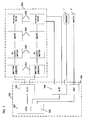
- the block-diagram of the entire system including a gravity compensation controller, an exoskeleton actuator system and a human and an exoskeleton is shown in Figure 3.
- the exoskeleton actuator/control system takes the desired assist torque that is calculated using the above controller and attempts to generate the desired torque at its output.
- the actual assist torque that is used to drive the human joints is the output of the actuator system.
- the gravity compensation controller and the exoskeleton actuator system constitute a human assist system.
- the human assist system comprises the gravity compensation controller 100 and the exoskeleton actuator system 200.
- the gravity compensation controller 100 has a CPU 101, a memory 102, a D/A converter 103, an A/D converter 104 and a digital input/output unit 105.
- the exoskeleton actuator system 200 has an actuator unit for applying a desired assist torque to each of the joints.
- the joints include both ankle joints, both knee joints and both hip joints.
- a plurality of actuator units are provided for these joints.
- Each actuator unit includes a motor driver 201, DC servomotor 202, a gear 203 and a potentiometer 204.
- G g(1) may be obtained through measurement with a ground reaction force sensor 1.
- the ground reaction force sensor 1 may be a load-cell type one set either on the bottom side of a foot or on the floor. Alternatively, G g(1) may be obtained using data stored in the memory 102.
- the center of pressure under each foot may be calculated or measured using in-shoe pressure sensor.
- the body segment parameters, such as mass of each segment, location of the center of mass of each segment, and lengths of each segment may be obtained using regression equations as reported in, Winter D.A(1990), Biomechanic and Motor Control of Human Movement, 2 nd Edition, Jhon Wiley & Sons, Inc.
- the mass of an external load, lifted or carried, by the person may be known from prior measurement.
- the mass may be assumed to be equally shared by the right side segments and the left side segments.
- a joint angle with respect to the vertical (joint inclining angle) ⁇ i may be obtained based on an output of the potentiometer 204 at each joint.
- the output of the potentiometer 204 represents a bending angle at the joint (joint bending angle).
- a joint angle with respect to the vertical ⁇ i can be calculated from a bending angle at each joint.
- the gravity compensation controller 100 delivers a desired value of assist torque for each joint, to each motor driver 201 of each actuator unit through D/A converter 103.
- the motor driver 201 drives the DC servomotor 202 to deliver the desired assist torque to each joint.
- Figure 6 is a flowchart of operational process of the human assist system.
- step S605 time is set to zero when the start switch 2 is turned on.
- step S610 the static vertical component of ground reaction force is obtained through measurement or estimation.
- a joint angle with respect to the vertical ⁇ i (orientation of segment i) is obtained through a sensor, which may be the potentiometer at each joint.
- a desired assist torque at joint i to overcome gravitational forces is calculated based on Equations 22 to 29.
- step 625 it is determined whether or not calculations have been carried out for all segments. If the calculations have not been carried out for any of the segments, a counter for i is incremented by 1 at step S630 and then the process returns to step S615. Otherwise, the process proceeds with step S635.
- a desired assist torque is delivered to each actuator unit through D/A converter in order to generate the desired assist torque.
- the process waits a certain time interval.
- step S645 it is determined whether or not the stop switch 2 is turned on. If the result of the determination is affirmative, the process ends. If the result of the determination is negative, the process returns to step S610.
- the gravity compensation protocols are simulated for a lifting/lowering motion of a mass representing a manual material handling task.
- a six-link planar system modeling the foot, lower leg, upper leg, torso, upper arm, and lower arm is used to conduct the analysis, as shown in Figure 4.
- the effect of dynamic factors and external mass on the various kinetic and kinematic parameters of the lift have been studied extensively by biomechanists. References should be made to the following documents.
- Figure 7 shows a motion trajectories at the five joints for a lifting and lowering motion of a 10 kg mass.
- Figure 8 shows simulated comparison of the magnitude of the assist torque, muscle torque, and net joint torque at the knee.
- gravity compensation control increases the mechanical power required by the muscles to perform the task.
- Our analysis cannot predict whether metabolic power is increased or decreased at each time instant. More sophisticated tools are required to fully understand the effect of gravity compensation on the metabolic cost. Moreover, gravity compensation may in fact improve stability at the expense of increased mechanical work.
- Figure 9 shows simulated comparison of the magnitude of the assist torque, muscle torque, and net joint torque at the hip.
- Gravity compensation control increases the mechanical power required by the muscle to perform the task in the region where the muscle torque at the hip exceeds the net joint torque at the hip.
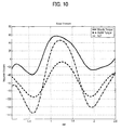
- Figure 10 shows simulated comparison of the assist torque, muscle torque, and net joint torque at the knee. Gravity compensation decreases the efficiency of motion in the region where the assist torque and net joint torque have opposite signs.
- Figure 11 shows simulated comparison of the assist torque, muscle torque, and net joint torque at the hip. Gravity compensation decreases the efficiency of motion in the region where the assist torque and net joint torque have opposite signs.
- Figure 12 shows quantities for estimating joint power at the knee, including the joint torque (top), and joint angular velocity (middle).
- the joint power is plotted in the bottom graph.
- Figure 14 shows feasibility region of assist torque vs. net joint torque at the knee joint. The feasibility region of gravity assist is denoted by the blue 'x' plot ticks.
- Figure 15 shows feasibility region of assist torque vs. net joint torque at the knee joint.
- the feasibility region of gravity assist is denoted by the blue 'x' plot ticks.
- the region with the 'o' plot ticks produce voluntary muscle torque which are not feasible.
- FIGs 8 to 11 show that muscle torques at knee and hip joints are considerably reduced in comparison with net joint torques. This means that the iterative "ground up" gravity compensation has significantly reduced the work required by the muscles to perform this task.
Abstract
Description


Claims (24)
- A method for obtaining an assist torque to be applied to a human joint, in a human assist system for applying an assist torque to the human joint to reduce load of muscles, comprising the steps of:determining whether the assist torques to be applied to the joint will increase or decrease the muscle mechanical power at the joint at a given instant in time;obtaining a moment due to gravity, acting on a joint of each human segment, based on equations of force and moment balance on each segment; andobtaining an assist torque to be applied to the joint to compensate for the moment due to gravity, acting on the joint.
- A method according to claim 1, wherein a moment due to gravity, acting on the joint is obtained based on a ground reaction force acting on the foot, the center of pressure under the foot, and an inclining angle of each segment in the step of obtaining a moment due to gravity, acting on the joint.
- A method according to claim 1 or 2, wherein terms of accelerations except those of the acceleration of gravity, terms of angular acceleration and terms of horizontal forces are set to zero in the equations of force and moment balance on each segment, to obtain a moment due to gravity, acting on the joint.
- A method according to claim 1 or 2, wherein the applied torque at any given joint is estimated by calculating the net torque due to gravitation acceleration.
- A method according to any one of claims 1 to 4, wherein a ground reaction force is obtained based on a measurement of a sensor.
- A method according to any one of claims 1 to 4, wherein a ground reaction force is obtained based on predetermined constants.
- A method according to any one of claims 1 to 6, wherein an assist torque is obtained in real time through real time processing.
- A method according to any one of claims 1 to 7, wherein segments include, a foot, a shin and a thigh.
- A method according to any one of claims 1 to 8, wherein an inclining angle of each segment is based on a measurement of a sensor.
- A method according to claim 9, wherein the sensor is a joint angle sensor which indicates a joint bending angle.
- A method according to claim 10, wherein the joint angle sensor is a potentiometer.
- A method according to any one of claims 1 to 11, used during a period of human operations of lifting and lowering a load.
- A human assist system for delivering an assist torque to a human joint to reduce load of muscles, comprising
a motor for delivering an assist torque to a joint,
a motor driver for driving control of the motor, and
a controller for determining a desired value of an assist torque, the controller comprising a processor and a memory and being configured to obtain a moment due to gravity, acting on a joint of each human segment, based on equations of force and moment balance on each segment and then to obtain an assist torque to be applied to the joint to compensate for the moment due to gravity, acting on the joint. - A human assist system according to claim 13, wherein the system is of exoskeleton type.
- A human assist system according to claim 13 or 14, wherein a moment due to gravity, acting on the joint is obtained by a ground reaction force acting on the foot and an inclining angle of each segment in the step of obtaining a moment due to gravity, acting on the joint.
- A human assist system according to any one of claims 13 to 15, wherein terms of accelerations except those of the acceleration of gravity, terms of angular acceleration and terms of horizontal forces are set to zero in the equations of force and moment balance on each segment, to obtain a moment due to gravity, acting on the joint.
- A human assist system according to any one of claims 13 to 16, wherein the system further comprises a sensor for detecting a ground reaction force and a ground reaction force is obtained based on a measurement of the sensor.
- A human assist system according to any one of claims 13 to 16, wherein the system further comprises a sensor for detecting the center of pressure and the center of pressure is obtained based on a measurement of the sensor.
- A human assist system according to any one of claims 13 to 16, wherein a ground reaction force is obtained based on predetermined constants.
- A human assist system according to any one of claims 13 to 19, wherein an assist torque is obtained in real time through real time processing.
- A human assist system according to any one of claims 13 to 20, wherein the system further comprises a sensor for obtaining an inclining angle of each segment.
- A human assist system according to claim 21, wherein the sensor is a joint angle sensor which indicates a joint bending angle.
- A human assist system according to claim 22, wherein the joint angle sensor is a potentiometer.
- A computer software program product, iplementing a method according to any of claims 1 to 12 when running on a computing device.
Applications Claiming Priority (6)
| Application Number | Priority Date | Filing Date | Title |
|---|---|---|---|
| US41302402P | 2002-09-23 | 2002-09-23 | |
| US413024P | 2002-09-23 | ||
| US42196402P | 2002-10-28 | 2002-10-28 | |
| US421964P | 2002-10-28 | ||
| US48470803P | 2003-07-03 | 2003-07-03 | |
| US484708P | 2003-07-03 |
Publications (3)
| Publication Number | Publication Date |
|---|---|
| EP1422128A2 true EP1422128A2 (en) | 2004-05-26 |
| EP1422128A3 EP1422128A3 (en) | 2008-12-17 |
| EP1422128B1 EP1422128B1 (en) | 2010-11-17 |
Family
ID=32234189
Family Applications (1)
| Application Number | Title | Priority Date | Filing Date |
|---|---|---|---|
| EP03021211A Expired - Lifetime EP1422128B1 (en) | 2002-09-23 | 2003-09-18 | Gravity compensation method in a human assist system and a human assist system with gravity compensation control |
Country Status (5)
| Country | Link |
|---|---|
| US (1) | US7217247B2 (en) |
| EP (1) | EP1422128B1 (en) |
| JP (1) | JP4493961B2 (en) |
| AT (1) | ATE488424T1 (en) |
| DE (1) | DE60334966D1 (en) |
Cited By (9)
| Publication number | Priority date | Publication date | Assignee | Title |
|---|---|---|---|---|
| WO2006110895A2 (en) | 2005-04-12 | 2006-10-19 | Honda Motor Co., Ltd. | Active control of an ankle-foot orthosis |
| EP1750641A2 (en) * | 2004-04-13 | 2007-02-14 | HONDA MOTOR CO., Ltd. | Gravity compensation control system and method using multiple feasibility parameters |
| EP1864278A2 (en) * | 2005-04-01 | 2007-12-12 | HONDA MOTOR CO., Ltd. | An exoskeleton controller for a human-exoskeleton system |
| EP2033612A1 (en) * | 2006-06-12 | 2009-03-11 | HONDA MOTOR CO., Ltd. | Control device for walking assistance device |
| US7623944B2 (en) | 2001-06-29 | 2009-11-24 | Honda Motor Co., Ltd. | System and method of estimating joint loads in a three-dimensional system |
| US7650204B2 (en) | 2001-06-29 | 2010-01-19 | Honda Motor Co., Ltd. | Active control of an ankle-foot orthosis |
| US7684896B2 (en) | 2001-06-29 | 2010-03-23 | Honda Motor Co., Ltd. | System and method of estimating joint loads using an approach of closed form dynamics |
| US8082062B2 (en) | 2005-06-10 | 2011-12-20 | Honda Motor Co., Ltd. | Regenerative actuation in motion control |
| ITFI20110232A1 (en) * | 2011-10-21 | 2013-04-22 | Zionamento Sant Anna | METHOD FOR CALCULATING THE MASS CENTER FOR A UMANOID PLATFORM |
Families Citing this family (46)
| Publication number | Priority date | Publication date | Assignee | Title |
|---|---|---|---|---|
| US7217247B2 (en) | 2002-09-23 | 2007-05-15 | Honda Giken Kogyo Kabushiki Kaisha | Gravity compensation method in a human assist system and a human assist system with gravity compensation control |
| US7469166B2 (en) * | 2001-06-29 | 2008-12-23 | Honda Motor Co., Ltd. | System and method of predicting novel motion in a serial chain system |
| US7135003B2 (en) * | 2001-06-29 | 2006-11-14 | Honda Giken Kogyo Kabushiki Kaisha | Feedback estimation of joint forces and joint moments |
| EP1306792B1 (en) * | 2001-10-29 | 2015-05-27 | Honda Giken Kogyo Kabushiki Kaisha | Simulation system and method for human augmentation devices |
| US7402142B2 (en) * | 2002-09-23 | 2008-07-22 | Honda Giken Kogyo Kabushiki Kaisha | Method and processor for obtaining moments and torques in a biped walking system |
| US6966882B2 (en) * | 2002-11-25 | 2005-11-22 | Tibion Corporation | Active muscle assistance device and method |
| JP4178186B2 (en) * | 2003-08-21 | 2008-11-12 | 国立大学法人 筑波大学 | Wearable motion assist device, control method for wearable motion assist device, and control program |
| US7628766B1 (en) * | 2003-10-29 | 2009-12-08 | The Regents Of The University Of California | Lower extremity enhancer |
| WO2005098733A2 (en) * | 2004-03-31 | 2005-10-20 | Honda Motor Co., Ltd. | Systems and methods for controlling a legged robot based on rate of change of angular momentum |
| WO2006092872A1 (en) * | 2005-02-28 | 2006-09-08 | National University Corporation NARA Institute of Science and Technology | Driving force computing device, driving force computing method, muscle force assisting device, program, and computer-readable recording medium |
| US7835822B2 (en) * | 2005-03-30 | 2010-11-16 | Honda Motor Co., Ltd. | Systems and methods for controlling a legged robot using a two-phase disturbance response strategy |
| WO2006113520A2 (en) * | 2005-04-13 | 2006-10-26 | The Regents Of The University Of California | Semi-powered lower extremity exoskeleton |
| US7573477B2 (en) * | 2005-06-17 | 2009-08-11 | Honda Motor Co., Ltd. | System and method for activation-driven muscle deformations for existing character motion |
| JP4666644B2 (en) * | 2006-07-12 | 2011-04-06 | 本田技研工業株式会社 | Control device for walking aids |
| US8353854B2 (en) | 2007-02-14 | 2013-01-15 | Tibion Corporation | Method and devices for moving a body joint |
| WO2008106611A1 (en) * | 2007-02-28 | 2008-09-04 | Raytheon Sarcos, Llc | Antagonistic fluid control system for active and passive actuator operation |
| EP2122186A1 (en) * | 2007-02-28 | 2009-11-25 | Raytheon Sarcos, LLC | Fluid control system having selective recruitable actuators |
| AU2009249191B2 (en) | 2008-05-20 | 2014-07-24 | Ekso Bionics, Inc. | Device and method for decreasing energy consumption of a person by use of a lower extremity exoskeleton |
| US20090306548A1 (en) | 2008-06-05 | 2009-12-10 | Bhugra Kern S | Therapeutic method and device for rehabilitation |
| US9351855B2 (en) | 2008-06-16 | 2016-05-31 | Ekso Bionics, Inc. | Powered lower extremity orthotic and method of operation |
| EP2346447B1 (en) * | 2008-07-23 | 2019-09-04 | Ekso Bionics, Inc. | An exoskeleton and method for controlling a swing leg of the exoskeleton |
| US9072463B2 (en) | 2009-01-27 | 2015-07-07 | University Of Washington | Prosthetic limb monitoring system |
| US20100312083A1 (en) * | 2009-04-20 | 2010-12-09 | Phil Southerland | System for Monitoring Glucose and Measuring Wattage |
| KR20120060578A (en) * | 2010-12-02 | 2012-06-12 | 삼성전자주식회사 | Walking robot and method for controlling balancing the same |
| KR20120071599A (en) * | 2010-12-23 | 2012-07-03 | 삼성전자주식회사 | Walking robot and control method thereof |
| US9855181B2 (en) | 2013-03-15 | 2018-01-02 | Bionik Laboratories, Inc. | Transmission assembly for use in an exoskeleton apparatus |
| US9889058B2 (en) | 2013-03-15 | 2018-02-13 | Alterg, Inc. | Orthotic device drive system and method |
| US9675514B2 (en) | 2013-03-15 | 2017-06-13 | Bionik Laboratories, Inc. | Transmission assembly for use in an exoskeleton apparatus |
| US9421143B2 (en) | 2013-03-15 | 2016-08-23 | Bionik Laboratories, Inc. | Strap assembly for use in an exoskeleton apparatus |
| US9808390B2 (en) | 2013-03-15 | 2017-11-07 | Bionik Laboratories Inc. | Foot plate assembly for use in an exoskeleton apparatus |
| US20150025423A1 (en) | 2013-07-19 | 2015-01-22 | Bionik Laboratories, Inc. | Control system for exoskeleton apparatus |
| KR102115950B1 (en) * | 2013-11-07 | 2020-06-05 | 삼성전자주식회사 | A walk-assistive robot and a method for controlling the walk-assistive robot |
| KR102131277B1 (en) * | 2013-12-30 | 2020-07-07 | 삼성전자주식회사 | A walk-assistive apparatus and a method for controlling the walk-assistive apparatus |
| US9757254B2 (en) * | 2014-08-15 | 2017-09-12 | Honda Motor Co., Ltd. | Integral admittance shaping for an exoskeleton control design framework |
| US11938050B2 (en) * | 2015-12-14 | 2024-03-26 | Board Of Regents, The University Of Texas System | Torque control methods and devices for powered orthosis |
| JP6909783B2 (en) * | 2016-06-08 | 2021-07-28 | 任天堂株式会社 | Passive walking device and passive walking module |
| US10195098B2 (en) | 2016-09-22 | 2019-02-05 | Gordon Roeder | Decompression chair for lower back |
| US11844667B2 (en) | 2016-11-02 | 2023-12-19 | Joe Johnson | Disarticulated compression socket |
| US10004614B1 (en) | 2016-11-02 | 2018-06-26 | Joe Johnson | Disarticulated compression socket |
| US10710237B2 (en) * | 2017-03-22 | 2020-07-14 | Jtekt Corporation | Assist device |
| CN109634100B (en) * | 2018-12-30 | 2021-11-02 | 深圳市优必选科技有限公司 | Humanoid robot walking acceleration compensation method and device and humanoid robot |
| US11123608B2 (en) * | 2019-03-05 | 2021-09-21 | Hiwin Technologies Corp. | Upper limb training system and control method thereof |
| KR102234788B1 (en) | 2020-07-01 | 2021-04-01 | 삼성전자주식회사 | A walk-assistive apparatus and a method for controlling the walk-assistive apparatus |
| CN111538234B (en) * | 2020-07-08 | 2020-10-09 | 深圳市优必选科技股份有限公司 | Task hierarchical control method and device, robot and readable storage medium |
| CN113043279B (en) * | 2021-04-15 | 2022-08-02 | 诺创智能医疗科技(杭州)有限公司 | Control method, controller, system, electronic device and medium for surgical robot |
| CN113696177B (en) * | 2021-07-29 | 2022-12-27 | 杭州程天科技发展有限公司 | Control and evaluation method and system applied to exoskeleton robot |
Citations (1)
| Publication number | Priority date | Publication date | Assignee | Title |
|---|---|---|---|---|
| US5551308A (en) | 1994-07-06 | 1996-09-03 | Agency Of Industrial Science & Technology, Ministry Of International Trade & Industry | Method and apparatus for controlling a force assist apparatus |
Family Cites Families (53)
| Publication number | Priority date | Publication date | Assignee | Title |
|---|---|---|---|---|
| US4244120A (en) * | 1979-06-11 | 1981-01-13 | The United States Of America As Represented By The Secretary Of The Navy | Acceleration cueing simulation device |
| US5136227A (en) * | 1985-09-10 | 1992-08-04 | Agency Of Industrial Science & Technology, Ministry Of International Trade & Industry | Active gravity compensation device for force control system |
| US4786847A (en) * | 1986-11-20 | 1988-11-22 | Unimation Inc. | Digital control for multiaxis robots |
| JPS63150176A (en) * | 1986-12-15 | 1988-06-22 | 工業技術院長 | Walking control method of dynamic walking robot |
| US5044360A (en) * | 1989-12-26 | 1991-09-03 | United States Manufacturing Company | Orthosis with variable motion controls |
| JP3104249B2 (en) * | 1990-10-17 | 2000-10-30 | オムロン株式会社 | Feedback control device |
| US5625577A (en) * | 1990-12-25 | 1997-04-29 | Shukyohojin, Kongo Zen Sohonzan Shorinji | Computer-implemented motion analysis method using dynamics |
| US5432417A (en) * | 1992-04-30 | 1995-07-11 | Honda Giken Kogyo Kabushiki Kaisha | Locomotion control system for legged mobile robot |
| JP3269852B2 (en) * | 1992-05-29 | 2002-04-02 | 本田技研工業株式会社 | Posture stabilization control device for legged mobile robot |
| US5362288A (en) * | 1993-03-26 | 1994-11-08 | Eli Razon | Device for assisting running, walking or jumping |
| US5323549A (en) * | 1993-08-16 | 1994-06-28 | Sports Licensing, Inc. | Shoe equipped with internal orthotic cradle device |
| US5570286A (en) * | 1993-12-23 | 1996-10-29 | Lord Corporation | Regenerative system including an energy transformer which requires no external power source to drive same |
| US5835693A (en) * | 1994-07-22 | 1998-11-10 | Lynch; James D. | Interactive system for simulation and display of multi-body systems in three dimensions |
| US5659480A (en) * | 1995-06-27 | 1997-08-19 | Industrial Service And Machine, Incorporated | Method for coordinating motion control of a multiple axis machine |
| WO1997010081A1 (en) * | 1995-09-11 | 1997-03-20 | Kabushiki Kaisha Yaskawa Denki | Robot controller |
| US5808433A (en) * | 1995-09-29 | 1998-09-15 | Honda Giken Kogyo Kabushiki Kaisha | Method of generating gait of legged walking robot and system for controlling its locomotion |
| US5706589A (en) * | 1996-06-13 | 1998-01-13 | Marc; Michel | Energy managing shoe sole construction |
| US5982389A (en) * | 1996-06-17 | 1999-11-09 | Microsoft Corporation | Generating optimized motion transitions for computer animated objects |
| RU2107328C1 (en) | 1996-08-14 | 1998-03-20 | Нурахмед Нурисламович Латыпов | Method for tracing and displaying of position and orientation of user in three-dimensional space and device which implements said method |
| US6364888B1 (en) * | 1996-09-09 | 2002-04-02 | Intuitive Surgical, Inc. | Alignment of master and slave in a minimally invasive surgical apparatus |
| DE69734835T2 (en) * | 1996-12-19 | 2006-07-20 | Honda Giken Kogyo K.K. | POSITIVE CONTROLLER ON A ROBOT MOVING ON LEGS |
| JP3375843B2 (en) * | 1997-01-29 | 2003-02-10 | 本田技研工業株式会社 | Robot autonomous traveling method and autonomous traveling robot control device |
| US5942869A (en) * | 1997-02-13 | 1999-08-24 | Honda Giken Kogyo Kabushiki Kaisha | Mobile robot control device |
| DE29719250U1 (en) * | 1997-10-30 | 1998-05-07 | Hauptverband Der Gewerblichen | Body stress measurement and analysis system |
| US6161080A (en) * | 1997-11-17 | 2000-12-12 | The Trustees Of Columbia University In The City Of New York | Three dimensional multibody modeling of anatomical joints |
| US6045524A (en) * | 1997-12-19 | 2000-04-04 | Kabushiki Kaisha Tatematsu Seisakusho | Joint of orthotic apparatus |
| DE69943148D1 (en) * | 1998-04-20 | 2011-03-03 | Honda Motor Co Ltd | CONTROL UNIT FOR A LEG ROBOT |
| AU772012B2 (en) | 1998-09-14 | 2004-04-08 | Board Of Trustees Of The Leland Stanford Junior University | Assessing the condition of a joint and preventing damage |
| JP3497402B2 (en) | 1999-02-25 | 2004-02-16 | 日本電信電話株式会社 | Exercise state generation device and recording medium recording exercise state generation program |
| SE514921C2 (en) * | 1999-06-22 | 2001-05-21 | Atlas Copco Tools Ab | Method for determining optimal values for screw tightening parameters by operating simulation |
| JP3555107B2 (en) * | 1999-11-24 | 2004-08-18 | ソニー株式会社 | Legged mobile robot and operation control method for legged mobile robot |
| JP3615702B2 (en) * | 1999-11-25 | 2005-02-02 | ソニー株式会社 | Motion control device and motion control method for legged mobile robot, and legged mobile robot |
| US6750866B1 (en) * | 2000-04-21 | 2004-06-15 | Realistic Dynamics, Inc. | Method and system for dynamically filtering the motion of articulated bodies |
| US6633783B1 (en) * | 2000-06-06 | 2003-10-14 | Honda Giken Kogyo Kabushiki Kaisha | Fuzzy logic based control |
| US6445983B1 (en) * | 2000-07-07 | 2002-09-03 | Case Corporation | Sensor-fusion navigator for automated guidance of off-road vehicles |
| JP4625910B2 (en) * | 2000-09-19 | 2011-02-02 | 学校法人東海大学 | Mobile robot joint control device |
| JP4252721B2 (en) * | 2000-11-17 | 2009-04-08 | 本田技研工業株式会社 | Biped robot |
| JP3760186B2 (en) * | 2001-06-07 | 2006-03-29 | 独立行政法人科学技術振興機構 | Biped walking type moving device, walking control device thereof, and walking control method |
| DE10130485C2 (en) * | 2001-06-25 | 2003-06-26 | Robert Riener | Programmable joint simulator |
| JP4611580B2 (en) * | 2001-06-27 | 2011-01-12 | 本田技研工業株式会社 | Torque application system |
| US7623944B2 (en) * | 2001-06-29 | 2009-11-24 | Honda Motor Co., Ltd. | System and method of estimating joint loads in a three-dimensional system |
| US7135003B2 (en) * | 2001-06-29 | 2006-11-14 | Honda Giken Kogyo Kabushiki Kaisha | Feedback estimation of joint forces and joint moments |
| US7390309B2 (en) * | 2002-09-23 | 2008-06-24 | Honda Motor Co., Ltd. | Human assist system using gravity compensation control system and method using multiple feasibility parameters |
| US7217247B2 (en) | 2002-09-23 | 2007-05-15 | Honda Giken Kogyo Kabushiki Kaisha | Gravity compensation method in a human assist system and a human assist system with gravity compensation control |
| JP3944566B2 (en) * | 2001-07-30 | 2007-07-11 | 国立大学法人 東京大学 | A method of dynamically determining joint acceleration in a link mechanism. |
| JP3637387B2 (en) * | 2001-09-07 | 2005-04-13 | 国立大学法人岐阜大学 | Attitude control device and control method for machine having legs |
| JP3833567B2 (en) * | 2002-05-01 | 2006-10-11 | 本田技研工業株式会社 | Mobile robot attitude control device |
| EP1550401A4 (en) * | 2002-05-29 | 2008-03-19 | Japan Science & Tech Agency | Body mechanics calculating method, body mechanics model, its model data, and body model producing method |
| US6971267B2 (en) * | 2002-09-23 | 2005-12-06 | Honda Giken Kogyo Kabushiki Kaisha | Method and processor for obtaining moments and torques in a biped walking system |
| JP2004174704A (en) * | 2002-11-14 | 2004-06-24 | Sony Corp | Actuator device and multishaft type robot |
| US6966882B2 (en) * | 2002-11-25 | 2005-11-22 | Tibion Corporation | Active muscle assistance device and method |
| US8579771B2 (en) * | 2004-08-11 | 2013-11-12 | Omnitek Partners Llc | Walk-assist devices and methods |
| US20060139355A1 (en) * | 2004-12-27 | 2006-06-29 | Seyoon Tak | Physically based motion retargeting filter |
-
2003
- 2003-09-05 US US10/655,460 patent/US7217247B2/en active Active
- 2003-09-18 EP EP03021211A patent/EP1422128B1/en not_active Expired - Lifetime
- 2003-09-18 DE DE60334966T patent/DE60334966D1/en not_active Expired - Lifetime
- 2003-09-18 AT AT03021211T patent/ATE488424T1/en not_active IP Right Cessation
- 2003-09-22 JP JP2003330149A patent/JP4493961B2/en not_active Expired - Fee Related
Patent Citations (1)
| Publication number | Priority date | Publication date | Assignee | Title |
|---|---|---|---|---|
| US5551308A (en) | 1994-07-06 | 1996-09-03 | Agency Of Industrial Science & Technology, Ministry Of International Trade & Industry | Method and apparatus for controlling a force assist apparatus |
Cited By (16)
| Publication number | Priority date | Publication date | Assignee | Title |
|---|---|---|---|---|
| US7774177B2 (en) | 2001-06-29 | 2010-08-10 | Honda Motor Co., Ltd. | Exoskeleton controller for a human-exoskeleton system |
| US7623944B2 (en) | 2001-06-29 | 2009-11-24 | Honda Motor Co., Ltd. | System and method of estimating joint loads in a three-dimensional system |
| US7684896B2 (en) | 2001-06-29 | 2010-03-23 | Honda Motor Co., Ltd. | System and method of estimating joint loads using an approach of closed form dynamics |
| US7650204B2 (en) | 2001-06-29 | 2010-01-19 | Honda Motor Co., Ltd. | Active control of an ankle-foot orthosis |
| EP1750641A4 (en) * | 2004-04-13 | 2010-01-27 | Honda Motor Co Ltd | Gravity compensation control system and method using multiple feasibility parameters |
| EP1750641A2 (en) * | 2004-04-13 | 2007-02-14 | HONDA MOTOR CO., Ltd. | Gravity compensation control system and method using multiple feasibility parameters |
| EP1864278A4 (en) * | 2005-04-01 | 2008-05-07 | Honda Motor Co Ltd | An exoskeleton controller for a human-exoskeleton system |
| EP1864278A2 (en) * | 2005-04-01 | 2007-12-12 | HONDA MOTOR CO., Ltd. | An exoskeleton controller for a human-exoskeleton system |
| EP1868546A4 (en) * | 2005-04-12 | 2008-05-21 | Honda Motor Co Ltd | Active control of an ankle-foot orthosis |
| EP1868546A2 (en) * | 2005-04-12 | 2007-12-26 | HONDA MOTOR CO., Ltd. | Active control of an ankle-foot orthosis |
| WO2006110895A2 (en) | 2005-04-12 | 2006-10-19 | Honda Motor Co., Ltd. | Active control of an ankle-foot orthosis |
| US8082062B2 (en) | 2005-06-10 | 2011-12-20 | Honda Motor Co., Ltd. | Regenerative actuation in motion control |
| EP2033612A1 (en) * | 2006-06-12 | 2009-03-11 | HONDA MOTOR CO., Ltd. | Control device for walking assistance device |
| EP2033612A4 (en) * | 2006-06-12 | 2009-06-24 | Honda Motor Co Ltd | Control device for walking assistance device |
| US8303521B2 (en) | 2006-06-12 | 2012-11-06 | Honda Motor Co., Ltd. | Control device for walking assistance device |
| ITFI20110232A1 (en) * | 2011-10-21 | 2013-04-22 | Zionamento Sant Anna | METHOD FOR CALCULATING THE MASS CENTER FOR A UMANOID PLATFORM |
Also Published As
| Publication number | Publication date |
|---|---|
| US20050102111A1 (en) | 2005-05-12 |
| JP4493961B2 (en) | 2010-06-30 |
| ATE488424T1 (en) | 2010-12-15 |
| JP2004114292A (en) | 2004-04-15 |
| EP1422128B1 (en) | 2010-11-17 |
| DE60334966D1 (en) | 2010-12-30 |
| EP1422128A3 (en) | 2008-12-17 |
| US7217247B2 (en) | 2007-05-15 |
Similar Documents
| Publication | Publication Date | Title |
|---|---|---|
| US7217247B2 (en) | Gravity compensation method in a human assist system and a human assist system with gravity compensation control | |
| US7390309B2 (en) | Human assist system using gravity compensation control system and method using multiple feasibility parameters | |
| EP1864278B1 (en) | An exoskeleton controller for a human-exoskeleton system | |
| US7713217B2 (en) | Torque imparting system | |
| US9980842B2 (en) | Motion assist device and motion assist method, computer program, and program recording medium | |
| US9427373B2 (en) | Wearable action-assist device and control program | |
| Lee et al. | Autonomous multi-joint soft exosuit for assistance with walking overground | |
| US20180141206A1 (en) | Exoskeleton | |
| Ugurlu et al. | Active compliance control reduces upper body effort in exoskeleton-supported walking | |
| WO2006110895A2 (en) | Active control of an ankle-foot orthosis | |
| Ahmed et al. | Survey of on-line control strategies of human-powered augmentation exoskeleton systems | |
| Noughaby et al. | The control of an exoskeleton and the reduction of interaction force using human intent detection by EMG signals and torque estimation | |
| Kamnik et al. | Human voluntary activity integration in the control of a standing-up rehabilitation robot: A simulation study | |
| Dariush | Analysis and simulation of an exoskeleton controller that accommodates static and reactive loads | |
| Hirata et al. | Control of wearable walking helper on slope based on integration of acceleration and GRF information | |
| Saccares et al. | A novel joint torque estimation method and sensory system for assistive lower limb exoskeletons | |
| Li et al. | Design of a crutch-exoskeleton assisted gait for reducing upper extremity loads✰ | |
| Hirata et al. | Motion control of wearable walking support system with accelerometer based on human model | |
| Hirata et al. | Motion control of wearable walking support system with accelerometer considering swing phase support | |
| RU2271176C2 (en) | Torque applying system | |
| Kim et al. | Development a Model for Analyzing the Walking Dynamic Simulation of Wearable Walking Assistant Robot |
Legal Events
| Date | Code | Title | Description |
|---|---|---|---|
| PUAI | Public reference made under article 153(3) epc to a published international application that has entered the european phase |
Free format text: ORIGINAL CODE: 0009012 |
|
| AK | Designated contracting states |
Kind code of ref document: A2 Designated state(s): AT BE BG CH CY CZ DE DK EE ES FI FR GB GR HU IE IT LI LU MC NL PT RO SE SI SK TR |
|
| AX | Request for extension of the european patent |
Extension state: AL LT LV MK |
|
| PUAL | Search report despatched |
Free format text: ORIGINAL CODE: 0009013 |
|
| AK | Designated contracting states |
Kind code of ref document: A3 Designated state(s): AT BE BG CH CY CZ DE DK EE ES FI FR GB GR HU IE IT LI LU MC NL PT RO SE SI SK TR |
|
| AX | Request for extension of the european patent |
Extension state: AL LT LV MK |
|
| 17P | Request for examination filed |
Effective date: 20090211 |
|
| AKX | Designation fees paid |
Designated state(s): AT BE BG CH CY CZ DE DK EE ES FI FR GB GR HU IE IT LI LU MC NL PT RO SE SI SK TR |
|
| 17Q | First examination report despatched |
Effective date: 20090918 |
|
| GRAP | Despatch of communication of intention to grant a patent |
Free format text: ORIGINAL CODE: EPIDOSNIGR1 |
|
| GRAC | Information related to communication of intention to grant a patent modified |
Free format text: ORIGINAL CODE: EPIDOSCIGR1 |
|
| GRAC | Information related to communication of intention to grant a patent modified |
Free format text: ORIGINAL CODE: EPIDOSCIGR1 |
|
| GRAS | Grant fee paid |
Free format text: ORIGINAL CODE: EPIDOSNIGR3 |
|
| GRAA | (expected) grant |
Free format text: ORIGINAL CODE: 0009210 |
|
| AK | Designated contracting states |
Kind code of ref document: B1 Designated state(s): AT BE BG CH CY CZ DE DK EE ES FI FR GB GR HU IE IT LI LU MC NL PT RO SE SI SK TR |
|
| REG | Reference to a national code |
Ref country code: GB Ref legal event code: FG4D |
|
| REG | Reference to a national code |
Ref country code: CH Ref legal event code: EP |
|
| REG | Reference to a national code |
Ref country code: IE Ref legal event code: FG4D |
|
| REF | Corresponds to: |
Ref document number: 60334966 Country of ref document: DE Date of ref document: 20101230 Kind code of ref document: P |
|
| REG | Reference to a national code |
Ref country code: NL Ref legal event code: VDEP Effective date: 20101117 |
|
| PG25 | Lapsed in a contracting state [announced via postgrant information from national office to epo] |
Ref country code: SE Free format text: LAPSE BECAUSE OF FAILURE TO SUBMIT A TRANSLATION OF THE DESCRIPTION OR TO PAY THE FEE WITHIN THE PRESCRIBED TIME-LIMIT Effective date: 20101117 Ref country code: SI Free format text: LAPSE BECAUSE OF FAILURE TO SUBMIT A TRANSLATION OF THE DESCRIPTION OR TO PAY THE FEE WITHIN THE PRESCRIBED TIME-LIMIT Effective date: 20101117 Ref country code: PT Free format text: LAPSE BECAUSE OF FAILURE TO SUBMIT A TRANSLATION OF THE DESCRIPTION OR TO PAY THE FEE WITHIN THE PRESCRIBED TIME-LIMIT Effective date: 20110317 Ref country code: FI Free format text: LAPSE BECAUSE OF FAILURE TO SUBMIT A TRANSLATION OF THE DESCRIPTION OR TO PAY THE FEE WITHIN THE PRESCRIBED TIME-LIMIT Effective date: 20101117 Ref country code: CY Free format text: LAPSE BECAUSE OF FAILURE TO SUBMIT A TRANSLATION OF THE DESCRIPTION OR TO PAY THE FEE WITHIN THE PRESCRIBED TIME-LIMIT Effective date: 20101117 Ref country code: BG Free format text: LAPSE BECAUSE OF FAILURE TO SUBMIT A TRANSLATION OF THE DESCRIPTION OR TO PAY THE FEE WITHIN THE PRESCRIBED TIME-LIMIT Effective date: 20110217 Ref country code: NL Free format text: LAPSE BECAUSE OF FAILURE TO SUBMIT A TRANSLATION OF THE DESCRIPTION OR TO PAY THE FEE WITHIN THE PRESCRIBED TIME-LIMIT Effective date: 20101117 Ref country code: AT Free format text: LAPSE BECAUSE OF FAILURE TO SUBMIT A TRANSLATION OF THE DESCRIPTION OR TO PAY THE FEE WITHIN THE PRESCRIBED TIME-LIMIT Effective date: 20101117 |
|
| PG25 | Lapsed in a contracting state [announced via postgrant information from national office to epo] |
Ref country code: GR Free format text: LAPSE BECAUSE OF FAILURE TO SUBMIT A TRANSLATION OF THE DESCRIPTION OR TO PAY THE FEE WITHIN THE PRESCRIBED TIME-LIMIT Effective date: 20110218 |
|
| PG25 | Lapsed in a contracting state [announced via postgrant information from national office to epo] |
Ref country code: BE Free format text: LAPSE BECAUSE OF FAILURE TO SUBMIT A TRANSLATION OF THE DESCRIPTION OR TO PAY THE FEE WITHIN THE PRESCRIBED TIME-LIMIT Effective date: 20101117 Ref country code: CZ Free format text: LAPSE BECAUSE OF FAILURE TO SUBMIT A TRANSLATION OF THE DESCRIPTION OR TO PAY THE FEE WITHIN THE PRESCRIBED TIME-LIMIT Effective date: 20101117 Ref country code: EE Free format text: LAPSE BECAUSE OF FAILURE TO SUBMIT A TRANSLATION OF THE DESCRIPTION OR TO PAY THE FEE WITHIN THE PRESCRIBED TIME-LIMIT Effective date: 20101117 Ref country code: ES Free format text: LAPSE BECAUSE OF FAILURE TO SUBMIT A TRANSLATION OF THE DESCRIPTION OR TO PAY THE FEE WITHIN THE PRESCRIBED TIME-LIMIT Effective date: 20110228 |
|
| PG25 | Lapsed in a contracting state [announced via postgrant information from national office to epo] |
Ref country code: RO Free format text: LAPSE BECAUSE OF FAILURE TO SUBMIT A TRANSLATION OF THE DESCRIPTION OR TO PAY THE FEE WITHIN THE PRESCRIBED TIME-LIMIT Effective date: 20101117 Ref country code: DK Free format text: LAPSE BECAUSE OF FAILURE TO SUBMIT A TRANSLATION OF THE DESCRIPTION OR TO PAY THE FEE WITHIN THE PRESCRIBED TIME-LIMIT Effective date: 20101117 Ref country code: SK Free format text: LAPSE BECAUSE OF FAILURE TO SUBMIT A TRANSLATION OF THE DESCRIPTION OR TO PAY THE FEE WITHIN THE PRESCRIBED TIME-LIMIT Effective date: 20101117 |
|
| PLBE | No opposition filed within time limit |
Free format text: ORIGINAL CODE: 0009261 |
|
| STAA | Information on the status of an ep patent application or granted ep patent |
Free format text: STATUS: NO OPPOSITION FILED WITHIN TIME LIMIT |
|
| 26N | No opposition filed |
Effective date: 20110818 |
|
| REG | Reference to a national code |
Ref country code: DE Ref legal event code: R097 Ref document number: 60334966 Country of ref document: DE Effective date: 20110818 |
|
| PG25 | Lapsed in a contracting state [announced via postgrant information from national office to epo] |
Ref country code: IT Free format text: LAPSE BECAUSE OF FAILURE TO SUBMIT A TRANSLATION OF THE DESCRIPTION OR TO PAY THE FEE WITHIN THE PRESCRIBED TIME-LIMIT Effective date: 20101117 |
|
| PG25 | Lapsed in a contracting state [announced via postgrant information from national office to epo] |
Ref country code: MC Free format text: LAPSE BECAUSE OF NON-PAYMENT OF DUE FEES Effective date: 20110930 |
|
| REG | Reference to a national code |
Ref country code: CH Ref legal event code: PL |
|
| REG | Reference to a national code |
Ref country code: IE Ref legal event code: MM4A |
|
| REG | Reference to a national code |
Ref country code: FR Ref legal event code: ST Effective date: 20120531 |
|
| PG25 | Lapsed in a contracting state [announced via postgrant information from national office to epo] |
Ref country code: CH Free format text: LAPSE BECAUSE OF NON-PAYMENT OF DUE FEES Effective date: 20110930 Ref country code: IE Free format text: LAPSE BECAUSE OF NON-PAYMENT OF DUE FEES Effective date: 20110918 Ref country code: LI Free format text: LAPSE BECAUSE OF NON-PAYMENT OF DUE FEES Effective date: 20110930 |
|
| PG25 | Lapsed in a contracting state [announced via postgrant information from national office to epo] |
Ref country code: FR Free format text: LAPSE BECAUSE OF NON-PAYMENT OF DUE FEES Effective date: 20110930 |
|
| PG25 | Lapsed in a contracting state [announced via postgrant information from national office to epo] |
Ref country code: LU Free format text: LAPSE BECAUSE OF NON-PAYMENT OF DUE FEES Effective date: 20110918 |
|
| PG25 | Lapsed in a contracting state [announced via postgrant information from national office to epo] |
Ref country code: TR Free format text: LAPSE BECAUSE OF FAILURE TO SUBMIT A TRANSLATION OF THE DESCRIPTION OR TO PAY THE FEE WITHIN THE PRESCRIBED TIME-LIMIT Effective date: 20101117 |
|
| PG25 | Lapsed in a contracting state [announced via postgrant information from national office to epo] |
Ref country code: HU Free format text: LAPSE BECAUSE OF FAILURE TO SUBMIT A TRANSLATION OF THE DESCRIPTION OR TO PAY THE FEE WITHIN THE PRESCRIBED TIME-LIMIT Effective date: 20101117 |
|
| PGFP | Annual fee paid to national office [announced via postgrant information from national office to epo] |
Ref country code: DE Payment date: 20130911 Year of fee payment: 11 |
|
| PGFP | Annual fee paid to national office [announced via postgrant information from national office to epo] |
Ref country code: GB Payment date: 20130918 Year of fee payment: 11 |
|
| REG | Reference to a national code |
Ref country code: DE Ref legal event code: R119 Ref document number: 60334966 Country of ref document: DE |
|
| GBPC | Gb: european patent ceased through non-payment of renewal fee |
Effective date: 20140918 |
|
| PG25 | Lapsed in a contracting state [announced via postgrant information from national office to epo] |
Ref country code: GB Free format text: LAPSE BECAUSE OF NON-PAYMENT OF DUE FEES Effective date: 20140918 Ref country code: DE Free format text: LAPSE BECAUSE OF NON-PAYMENT OF DUE FEES Effective date: 20150401 |