EP1422125A2 - Steering angle correction device - Google Patents
Steering angle correction device Download PDFInfo
- Publication number
- EP1422125A2 EP1422125A2 EP03026199A EP03026199A EP1422125A2 EP 1422125 A2 EP1422125 A2 EP 1422125A2 EP 03026199 A EP03026199 A EP 03026199A EP 03026199 A EP03026199 A EP 03026199A EP 1422125 A2 EP1422125 A2 EP 1422125A2
- Authority
- EP
- European Patent Office
- Prior art keywords
- steering
- control action
- steering angle
- error
- steering member
- Prior art date
- Legal status (The legal status is an assumption and is not a legal conclusion. Google has not performed a legal analysis and makes no representation as to the accuracy of the status listed.)
- Granted
Links
- 230000000977 initiatory effect Effects 0.000 claims abstract description 35
- 238000001514 detection method Methods 0.000 claims abstract description 34
- 230000001186 cumulative effect Effects 0.000 claims abstract description 10
- 230000036962 time dependent Effects 0.000 description 7
- 238000000034 method Methods 0.000 description 4
- 238000010276 construction Methods 0.000 description 3
- 230000007423 decrease Effects 0.000 description 2
- 238000010586 diagram Methods 0.000 description 2
- 239000003550 marker Substances 0.000 description 2
- 230000007774 longterm Effects 0.000 description 1
Images


Classifications
-
- B—PERFORMING OPERATIONS; TRANSPORTING
- B62—LAND VEHICLES FOR TRAVELLING OTHERWISE THAN ON RAILS
- B62D—MOTOR VEHICLES; TRAILERS
- B62D15/00—Steering not otherwise provided for
- B62D15/02—Steering position indicators ; Steering position determination; Steering aids
- B62D15/021—Determination of steering angle
- B62D15/0245—Means or methods for determination of the central position of the steering system, e.g. straight ahead position
Definitions
- the present invention relates to a steering angle correction device which is used to correct the detected error in the steering angle in a vehicle steering apparatus, in which the action of an actuator controlled in accordance with the detected value of the steering angle from the center point position of a steering member such as a steering wheel is transmitted to the vehicle wheels so that the vehicle steering angle varies.
- the steering member is not always positioned in the center point position even if the vehicle is advancing straight forward. Accordingly, it is conceivable that the steering angle from the center point position of the steering member might be detected using an absolute position detection sensor such as a potentiometer which outputs an analog signal with a value corresponding to the absolute position of the steering member.
- an absolute position detection sensor such as a potentiometer which outputs an analog signal with a value corresponding to the absolute position of the steering member.
- sensors which output an analog signal such as potentiometers have a large output error caused by a time-dependent change compared to sensors which output digital signals such as rotary encoders, so that the detection precision of such sensors drops in the case of long-term use.
- resistance elements of contact type potentiometers become worn as a result of contact with brushes, so that the output error caused by the time-dependent change is large.
- the determination of the steering angle by the combined use of a potentiometer and a rotary encoder, and the correction of the error in the determination of the steering angle based on the time-dependent change of the potentiometer have been proposed by the present applicant.
- the absolute position of the steering member at the time of initiation of control action of the steering actuator is determined from the output of the potentiometer, and the steering angle from the center point position of the steering member is subsequently determined from the number of pulses emitted by the rotary encoder in accordance with the steering angle of the steering member.
- the rotary encoder is disposed so as to output a Z-phase pulse signal when the steering member is positioned in the center point position.
- the steering angle determined from the output of the potentiometer and the number of pulses generated by the rotary encoder is zero at the point in time at which a Z-phase pulse signal is output. Accordingly, the steering angle from the center point position of the steering member can be accurately determined, by taking the steering angle from the center point position determined at the point in time at which a Z-phase pulse signal is output as the error in the steering angle and then correcting the steering angle by an amount corresponding to this error.
- the steering angle is corrected at the point in time at which the Z-phase pulse signal is output as a result of the steering member being positioned in the center point position, the steering angle abruptly varies during the control of the steering actuator so that the behavior of the vehicle may become unstable.
- the present invention is a steering angle correction device in a vehicle steering apparatus in which the action of a steering actuator controlled in accordance with the steering angle from the center point position of a steering member is transmitted to the vehicle wheels so that the vehicle steering angle varies
- the steering angle correction device comprising: an absolute position detection sensor which outputs an analog signal with a value corresponding to the absolute position of the steering member; a position sensor which outputs a steering angle detection signal corresponding to the variation in the steering angle of the steering member, and which outputs a position specifying signal when the steering member is in a predetermined specified position; means for determining the steering direction of the steering member; means for determining the steering initiation position, which is the absolute position of the steering member corresponding to the output value of the absolute position detection sensor at the time of initiation of control action, on the basis of a stored correspondence relationship between the absolute position of the steering member and the output value of the absolute position detection sensor; means for determining the reference position by correcting the steering initiation position by an amount corresponding to the reference error determined and stored in the preced
- the error in the steering angle caused by these fluctuations in the output value can be corrected. Furthermore, the timing of correction of this error is divided into the initiation of control action and the time at which the position specifying signal of the position sensor is generated, in which the error corresponding to the reference error in the preceding control action is corrected at the time when the control is initiated; accordingly, the amount of error correction at the time when the position specifying signal is generated can be reduced to a small amount of correction. As a result, abrupt variations in the vehicle steering angle caused by error correction during the control action can be reduced to small variations.
- the reference error determined during the preceding control action is desirable to use as the value corresponding to the cumulative value of the errors in the control actions up to the preceding control action.
- the steering angle correction device of the present invention it is desirable that means for storing the output value of the absolute position detection sensor at the time of the initiation of control action is provided, that the reference error for the next control action is stored with related to the output value of the absolute position detection sensor at the time of initiation of control action, and that the reference position is determined by correcting the steering initiation position by an amount corresponding to the reference error stored with related to the output value of the absolute position detection sensor at the time of initiation of control action.
- the steering angle correction device of the present invention abrupt variations in the steering angle caused by error correction during the control action can be reduced to slight variations, and the error correction can be performed with higher precision, so that the behavior of the vehicle can be prevented from becoming unstable.
- the vehicle steering apparatus shown in Fig. 1 comprises a steering member 1 as modeled by a steering wheel, a steering actuator 2, and steering gear 3 which transmits the action of the steering actuator 2 to the vehicle wheels 4 so that the vehicle steering angle varies without any mechanical linkage of the steering member 1 to the vehicle wheels 4.
- the steering member 1 is connected to an input side rotating shaft 10 which is supported by the vehicle body so that this rotating shaft 10 is free to rotate, thus causing the steering member 1 to rotate together with the rotating shaft 10.
- the output shaft of a resistance force generating actuator 19 is formed as an integral part of the input side rotating shaft 10.
- the resistance force generating actuator 19 can generate a torque that acts on the steering member 1.
- the resistance force generating actuator 19 can be constructed from an electric motor such as a brushless motor or the like.
- the steering actuator 2 can be constructed from an electric motor such as a brushless motor or the like.
- the steering gear 3 has a motion converting mechanism that converts the rotational motion of the output shaft of the steering actuator 2 into the rectilinear motion of a steering rod 7.
- the action of the steering rod 7 is transmitted to the vehicle wheels 4 via tie rods 8 and knuckle arms 9, so that the vehicle steering angle varies.
- a known gear can be used as the steering gear 3; there are no restrictions on the construction of the steering gear as long as it is capable of transmitting the action of the steering actuator 2 to the vehicle wheels 4 so that the vehicle steering angle varies.
- it can be constructed by forming ball screw shaft that is screw-engaged with ball nut driven by the steering actuator 2 as an integral part of the steering rod 7.
- the wheel alignment is set so that the vehicle wheels 4 can be returned to the straight forward position by a self-aligning torque in a state in which the steering actuator 2 is not being driven.
- a marker M is attached to the steering member 1.
- the steering member 1 of the present embodiment has a disk part 1a, and an annular grip 1b which surrounds the circumference of this disk part 1a.
- the marker M is formed substantially in a T shape, and has an indicator part M2 which is disposed along the radius of the disk part 1a. When the direction of length of this indicator part M2 is oriented along the forward-rearward direction of the vehicle, the steering member 1 is positioned in the center point position.
- An angle detection device 11 which detects the steering angle ⁇ h corresponding to the rotational angle of the input side rotating shaft 10 from the center point position as the steering angle from the center point position of the steering member 1.
- the angle detection device 11 has a potentiometer (absolute position detection sensor) 11a and a rotary encoder (position sensor) 11b.
- the potentiometer 11a outputs an analog signal with a value that corresponds to the absolute position of the steering member 1; for example, this potentiometer outputs an analog signal as a result of the position of contact between a variable resistance element and a brush varying due to the rotation of the steering member 1.
- the rotary encoder 11b generates an A-phase pulse signal whose number of pulses corresponding to the variation in the steering angle ⁇ h, and a B-phase pulse signal whose phase is shifted with respect to the A-phase pulse signal (e. g., whose phase is shifted by 1/4 period); furthermore, the rotary encoder 11b also generates a Z-phase pulse signal (position specifying signal) with each rotation of 360 degrees.
- the rotary encoder 11b is disposed so as to generate the Z-phase pulse signal when the steering member 1 is in a predetermined specified position (the center point position in the present embodiment).
- the potentiometer 11a and rotary encoder 11b are connected to a control device 20 constructed from a computer.
- the control device 20 stores a correspondence relationship between the output value ⁇ x of the potentiometer 11a and the absolute position of the steering member 1 expressed by the steering angle ⁇ h, and determines the steering initiation position ⁇ h( ⁇ x) which is the absolute position of the steering member 1 corresponding to the output value ⁇ x of the potentiometer 11a at the time of initiation of control action on the basis of this relationship. Furthermore, the control device 20 judges the steering direction of the steering member 1 according to whether the phase of the B-phase pulse signal is advanced or retarded with respect to the phase of the A-phase pulse signal.
- control device 20 stores the reference error ⁇ h determined in the preceding control action, and determines the reference position [ ⁇ h( ⁇ x) - ⁇ h] by correcting the steering initiation position ⁇ h( ⁇ x) by an amount corresponding to the reference error ⁇ h. Furthermore, the control device 20 stores a correspondence relationship between the number of pulses generated by the rotary encoder 11b and the variation in the steering angle ⁇ h, and determines the current position ⁇ hx of the steering member 1 from the determined reference position [ ⁇ h( ⁇ x) - ⁇ h], the number of pulses of the A-phase pulse signal generated by the steering of the steering member 1, and the steering direction of the steering member 1.
- the deviation between the current position ⁇ hx of the steering member 1 at the time when the Z-phase pulse signal is generated and the generation position (the center point position in the present embodiment) of the Z-phase pulse signal is taken as the error ⁇ in the current control action. Accordingly, the corrected position ( ⁇ hx - ⁇ ) of the steering member 1 is determined by correcting the current position ⁇ hx by an amount corresponding to the error ⁇ in the current control action.
- the corrected position ( ⁇ hx - ⁇ ) is used as the steering angle ⁇ h from the center point position.
- the control device 20 determines and stores the reference error ⁇ h for the next control action by adding the error ⁇ in the current control action to a value that corresponds to the cumulative value of the errors in the control actions up to the preceding control action.
- the reference error ⁇ h determined and stored in the preceding control action is used as this value that corresponds to the cumulative value of the errors in the control actions up to the preceding control action.
- the initial value of this reference error ⁇ h is set at zero.
- a torque sensor 12 which detects the torque that is transmitted by the input side rotating shaft 10 as the steering torque Th of the steering member 1
- a vehicle steering angle sensor 13 which detects the vehicle steering angle ⁇ as the amount of steering of the vehicle wheels 4 from the amount of movement of the steering rod 7, and a speed sensor 14 which detects the vehicle speed V are connected to the control device 20 constructed from a computer.
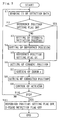
- control procedure of the control device 20 is described with reference to the flow chart shown in Fig. 3.
- step S3 the steering initiation position ⁇ h( ⁇ x) of the steering member 1 corresponding to the output value ⁇ x of the potentiometer 11a detected at the time of initiation of control action is determined (step S3), the reference position [ ⁇ h( ⁇ x) - ⁇ h] is determined by correcting the steering initiation position ⁇ h( ⁇ x) by an amount corresponding to the stored reference error ⁇ h (step S4), and the reference position setting flag is switched on (step S5).
- the current position ⁇ hx of the steering member 1 is determined from the determined reference position [ ⁇ h( ⁇ x) - ⁇ h], the number of pulses generated by the rotary encoder 11b as a result of the steering of the steering member 1, and the steering direction of the steering member 1 (step S6). If the reference position setting flag is on in step S2, the current position ⁇ hx of the steering member 1 is determined in step S6. Next, the error ⁇ of the current position ⁇ hx of the steering member 1 is set (step S7).
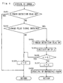
- the flow chart shown in Fig. 4 shows the setting procedure of the error ⁇ of the current position ⁇ hx of the steering member 1.
- a judgement is made as to whether or not the Z-phase detection flag is on (step S101). If this flag is not on, a judgement is made as to whether or not a Z-phase pulse signal has been detected (step S102). If such a signal has not been detected, the error ⁇ is set at zero, and the processing is returned (step S103).
- step S104 the Z-phase detection flag is switched on (step S104), and the deviation e between the current position ⁇ hx of the steering member 1 at the time when the Z-phase pulse signal is generated and the generation position (the center point position in the present embodiment) of the Z-phase pulse signal is determined (step S105).
- step S106 a judgement is made as to whether or not the determined deviation e is zero (step S106), and if this deviation is zero, the error ⁇ is set at zero, and the processing is returned.
- step S107 If the determined deviation e is not zero, the determined deviation e is set as the error ⁇ in the current control action (step S107), and a value obtained by adding this set error ⁇ to the stored reference error ⁇ h is stored as the reference error ⁇ h for the next control action. In this way, the reference error ⁇ h is updated (step S108). If the Z-phase detection flag is on in step S101, the processing is returned.
- the corrected position ( ⁇ hx - ⁇ ) of the steering member 1 is determined by correcting the current position ⁇ hx by an amount corresponding to this error ⁇ (step S8).
- the steering actuator 2 and the resistance force generating actuator 19 are controlled in accordance with the corrected position ( ⁇ hx - ⁇ ) of the steering member 1 (step S9).
- the target vehicle steering angle ⁇ * corresponding to the corrected position ( ⁇ hx - ⁇ ) of the steering member 1 and the detected vehicle speed V is determined from a stored relationship, and the steering actuator 2 is feedback-controlled so that the deviation between the target vehicle steering angle ⁇ * and the detected vehicle steering angle ⁇ is reduced, so that the detected vehicle steering angle ⁇ is zero when the steering member 1 is positioned in the center point position.
- this stored relationship is predetermined so that the target vehicle steering angle increases as the steering angle increases, and as the vehicle speed increases.
- the target operating torque Th* corresponding to the corrected position ( ⁇ hx - ⁇ ) of the steering member 1 and the detected vehicle speed V is determined from a stored relationship, and the resistance force generating actuator 19 is feedback-controlled so that the deviation between the target operating torque Th* and the detected operating torque Th is reduced.
- This stored relationship is predetermined so that, for example, the target operating torque decreases as the steering angle increases, and as the vehicle speed decreases.
- step S10 a judgement is made as to whether or not to end control action according to, for example, whether or not the ignition switch of the vehicle is on (step S10).
- the processing returns to step S1.
- the reference position setting flag and Z-phase detection flag are switched off (step S11), and the supply of power to the control device 20 is cut off, so that control action is ended.
- the present invention is not limited to the above-mentioned embodiment.
- the reference error ⁇ h is updated by storing a value obtained by adding the error ⁇ in the current control action to the stored reference error ⁇ h as the reference error ⁇ h for the next control action.
- a value obtained by adding the error ⁇ in the current control action to the arithmetical mean value of the stored reference errors ⁇ h in the above-mentioned plurality of immediately preceding control actions is stored as the reference error ⁇ h for the next control action.
- fluctuations in the reference error ⁇ h can be evened out by using the arithmetical mean value as a value corresponding to the cumulative value of the errors in the control actions up to the preceding control action.
- the set initial value (e. g., zero) can be used as the reference error ⁇ h until the number of immediately preceding control actions reaches the set number of control actions.
- step S106 of the flow chart shown in Fig. 4 a judgement as to whether or not the determined deviation e is zero is made in step S106 of the flow chart shown in Fig. 4. Instead of this, a judgement regarding the ending of control action is made in step S10 of the flow chart shown in Fig. 3; then, after the last output value ⁇ x' of the potentiometer 11a that has been detected is stored, control action is ended.
- step S106 a judgement is made as to whether or not the deviation e' between the output value ⁇ x of the potentiometer detected at the time of initiation of control action and the last output value ⁇ x' stored in the preceding control action is zero, and if this deviation e' is not zero, the deviation e' is set as the error ⁇ in step S107. On the other hand, if this deviation e' is zero, then the error ⁇ is set as zero in step S103.
- the reference error for the next control action is stored with related to the output value of the potentiometer 11a at the time of initiation of control action
- the reference position [ ⁇ h( ⁇ x) - ⁇ h] is determined by correcting the steering initiation position ⁇ h( ⁇ x) by an amount corresponding to the reference error ⁇ h stored with related to the output value of the potentiometer 11a stored at the time of initiation of control action.
- the reference position [ ⁇ h( ⁇ x) - ⁇ h] is determined by correcting the steering initiation position ⁇ h( ⁇ x) by an amount corresponding to the reference error ⁇ h stored with related to the output value ⁇ x of the potentiometer 11a detected at the time of initiation of control action. Further, in step S108 in Fig. 4, the value determined by adding the set error ⁇ to the reference error ⁇ h stored with related to the output value ⁇ x of the potentiometer 11a detected at the time of initiation of control action is stored with related to the output value ⁇ x as the reference error ⁇ h for the next control action.
- the error of the steering angle ⁇ h can be corrected in accordance with the non-uniformity of the output error of the potentiometer 11a.
- the output frequency of the potentiometer 11a increases in the vicinity of the center point position of the steering angle ⁇ h
- wear of the internal variable resistance of the potentiometer 11a and the like increase in the vicinity of the center point position of the steering angle ⁇ h.
- the output error of the potentiometer 11a is not uniform, but differs according to the steering angle ⁇ h.
- the precision of correction can be improved by correcting the error in the steering angle ⁇ h in accordance with such non-uniformity of the output error.
- the present invention can also be applied to a steering apparatus in which the steering wheel as the steering member is mechanically connected to the vehicle wheels, and in which the ratio of the steering angle of the steering wheel to the amount of steering of the vehicle wheels can be varied or cannot be varied.
- the steering direction instead of judging the steering direction according to whether the phase of the B-phase pulse signal is advanced or retarded with respect to the phase of the A-phase pulse signal, it is possible to judge this direction from the output value of the potentiometer 11a, or the detection value of a torque sensor that is separately installed in order to detect the steering torque. Moreover, it is also possible to output the Z-phase pulse signal when the steering member 1 is positioned in a position other than the center point position. Moreover, a resolver can also be used as the position sensor.
Landscapes
- Engineering & Computer Science (AREA)
- Chemical & Material Sciences (AREA)
- Combustion & Propulsion (AREA)
- Transportation (AREA)
- Mechanical Engineering (AREA)
- Steering Control In Accordance With Driving Conditions (AREA)
- Length Measuring Devices With Unspecified Measuring Means (AREA)
- Power Steering Mechanism (AREA)
- Transmission And Conversion Of Sensor Element Output (AREA)
- Steering Controls (AREA)
Abstract
Description
- The present invention relates to a steering angle correction device which is used to correct the detected error in the steering angle in a vehicle steering apparatus, in which the action of an actuator controlled in accordance with the detected value of the steering angle from the center point position of a steering member such as a steering wheel is transmitted to the vehicle wheels so that the vehicle steering angle varies.
- Conventionally, it is proposed to use a means for determining the center point position of a steering member and a rotary encoder which outputs a number of pulse signals corresponding to the determined steering angle from this center point position in order to detect the steering angle from the center point position of the steering member (Japanese Patent Application Laid-Open No. 2001-4313).
- In the conventional means for determining the center point position of the steering member, reflective type roadway boundary markers disposed along the roadway are detected by a laser beam emitted from the vehicle, a judgement as to whether or not the vehicle is advancing straight forward is made on the basis of these detection results, and in cases where the vehicle is advancing straight forward, the steering member is judged to be in the center point position. Accordingly, the construction of such means is complicated, and the cost is increased. Furthermore, in vehicles using a so-called steer-by-wire system in which the steering member and the vehicle wheels are not mechanically connected, and in vehicles in which the steering wheel and the vehicle wheels are mechanically connected so that the ratio of the steering angle of the steering wheel to the vehicle steering angle can be altered in accordance with the vehicle speed or the like, the steering member is not always positioned in the center point position even if the vehicle is advancing straight forward. Accordingly, it is conceivable that the steering angle from the center point position of the steering member might be detected using an absolute position detection sensor such as a potentiometer which outputs an analog signal with a value corresponding to the absolute position of the steering member. However, sensors which output an analog signal such as potentiometers have a large output error caused by a time-dependent change compared to sensors which output digital signals such as rotary encoders, so that the detection precision of such sensors drops in the case of long-term use. In particular, resistance elements of contact type potentiometers become worn as a result of contact with brushes, so that the output error caused by the time-dependent change is large.
- Accordingly, the determination of the steering angle by the combined use of a potentiometer and a rotary encoder, and the correction of the error in the determination of the steering angle based on the time-dependent change of the potentiometer, have been proposed by the present applicant. Specifically, the absolute position of the steering member at the time of initiation of control action of the steering actuator is determined from the output of the potentiometer, and the steering angle from the center point position of the steering member is subsequently determined from the number of pulses emitted by the rotary encoder in accordance with the steering angle of the steering member. Furthermore, the rotary encoder is disposed so as to output a Z-phase pulse signal when the steering member is positioned in the center point position. Consequently, if there is no error in the output of the potentiometer, the steering angle determined from the output of the potentiometer and the number of pulses generated by the rotary encoder is zero at the point in time at which a Z-phase pulse signal is output. Accordingly, the steering angle from the center point position of the steering member can be accurately determined, by taking the steering angle from the center point position determined at the point in time at which a Z-phase pulse signal is output as the error in the steering angle and then correcting the steering angle by an amount corresponding to this error.
- However, in cases where the output error of the potentiometer arising from the time-dependent change is large, the amount of correction of the steering angle at the point in time at which the above-mentioned Z-phase pulse signal is output becomes large. Accordingly, in cases where the control of the steering actuator is ended by stopping the vehicle in a state in which the steering member is positioned in a position other than the center point position, the detection error of the steering angle is large because no Z-phase pulse signal is output at the point in time at which the control action is initiated for the next starting of the vehicle. As a result, the steering actuator cannot be controlled in accordance with an accurate steering angle. Furthermore, since the steering angle is corrected at the point in time at which the Z-phase pulse signal is output as a result of the steering member being positioned in the center point position, the steering angle abruptly varies during the control of the steering actuator so that the behavior of the vehicle may become unstable.
- It is an object of the present invention to provide a steering angle correction device that can solve the above-mentioned problems.
- The present invention is a steering angle correction device in a vehicle steering apparatus in which the action of a steering actuator controlled in accordance with the steering angle from the center point position of a steering member is transmitted to the vehicle wheels so that the vehicle steering angle varies, the steering angle correction device comprising: an absolute position detection sensor which outputs an analog signal with a value corresponding to the absolute position of the steering member; a position sensor which outputs a steering angle detection signal corresponding to the variation in the steering angle of the steering member, and which outputs a position specifying signal when the steering member is in a predetermined specified position; means for determining the steering direction of the steering member; means for determining the steering initiation position, which is the absolute position of the steering member corresponding to the output value of the absolute position detection sensor at the time of initiation of control action, on the basis of a stored correspondence relationship between the absolute position of the steering member and the output value of the absolute position detection sensor; means for determining the reference position by correcting the steering initiation position by an amount corresponding to the reference error determined and stored in the preceding control action; means for determining the current position of the steering member from the reference position, the steering angle detection signal, the steering direction of the steering member, and a stored correspondence relationship between the steering angle detection signal and the variation in the steering angle of the steering member; means for determining the deviation between the current position of the steering member at the time when the position specifying signal is generated and the generation position of the position specifying signal as the error in the current control action; means for determining the corrected position of the steering member by correcting the current position by an amount corresponding to the error in the current control action; and means for determining and storing the reference error for the next control action by adding the error in the current control action to the cumulative value of the errors in the control actions up to the preceding control action; wherein the steering actuator is controlled in accordance with the corrected position of the steering member as the steering angle from the center point position of the steering member.
- In the present invention, even if the output value of the absolute position detection sensor fluctuates as a result of time-dependent change, the error in the steering angle caused by these fluctuations in the output value can be corrected. Furthermore, the timing of correction of this error is divided into the initiation of control action and the time at which the position specifying signal of the position sensor is generated, in which the error corresponding to the reference error in the preceding control action is corrected at the time when the control is initiated; accordingly, the amount of error correction at the time when the position specifying signal is generated can be reduced to a small amount of correction. As a result, abrupt variations in the vehicle steering angle caused by error correction during the control action can be reduced to small variations.
- In the steering angle correction device of the present invention, it is desirable to use the reference error determined during the preceding control action as the value corresponding to the cumulative value of the errors in the control actions up to the preceding control action. Alternatively, it is desirable to provide means for storing the reference errors in a plurality of immediately preceding control actions, and means for determining the arithmetical mean value of the stored reference errors in the plurality of control actions, and to use this arithmetical mean value as the value corresponding to the cumulative value of the errors in the control actions up to the preceding control action. In this way, fluctuations in the reference error can be evened out.
- In the steering angle correction device of the present invention, it is desirable that means for storing the output value of the absolute position detection sensor at the time of the initiation of control action is provided, that the reference error for the next control action is stored with related to the output value of the absolute position detection sensor at the time of initiation of control action, and that the reference position is determined by correcting the steering initiation position by an amount corresponding to the reference error stored with related to the output value of the absolute position detection sensor at the time of initiation of control action. As a result, in cases where the output error of the absolute position detection sensor is not uniform and differs according to the steering angle, the error in the steering angle can be corrected in accordance with the non-uniformity of the output error, so that the precision of correction can be improved.
- According to the steering angle correction device of the present invention, abrupt variations in the steering angle caused by error correction during the control action can be reduced to slight variations, and the error correction can be performed with higher precision, so that the behavior of the vehicle can be prevented from becoming unstable.
-
- Fig. 1 is a structural explanatory diagram of a vehicle steering apparatus in an embodiment of the present invention.
- Fig. 2 is a diagram which shows the steering member in the vehicle steering apparatus in the embodiment of the present invention.
- Fig. 3 is a flow chart which shows the control procedure of the resistance force generating actuator and steering actuator in the vehicle steering apparatus in the embodiment of the present invention.
- Fig. 4 is a flow chart which shows the setting procedure for the error of the current position of the steering member in the vehicle steering apparatus in the embodiment of the present invention.
-
- The vehicle steering apparatus shown in Fig. 1 comprises a steering member 1 as modeled by a steering wheel, a
steering actuator 2, andsteering gear 3 which transmits the action of thesteering actuator 2 to thevehicle wheels 4 so that the vehicle steering angle varies without any mechanical linkage of the steering member 1 to thevehicle wheels 4. - The steering member 1 is connected to an input
side rotating shaft 10 which is supported by the vehicle body so that this rotatingshaft 10 is free to rotate, thus causing the steering member 1 to rotate together with the rotatingshaft 10. The output shaft of a resistance force generating actuator 19 is formed as an integral part of the inputside rotating shaft 10. The resistance force generating actuator 19 can generate a torque that acts on the steering member 1. The resistance force generating actuator 19 can be constructed from an electric motor such as a brushless motor or the like. - The
steering actuator 2 can be constructed from an electric motor such as a brushless motor or the like. Thesteering gear 3 has a motion converting mechanism that converts the rotational motion of the output shaft of thesteering actuator 2 into the rectilinear motion of asteering rod 7. The action of thesteering rod 7 is transmitted to thevehicle wheels 4 viatie rods 8 and knuckle arms 9, so that the vehicle steering angle varies. A known gear can be used as thesteering gear 3; there are no restrictions on the construction of the steering gear as long as it is capable of transmitting the action of thesteering actuator 2 to thevehicle wheels 4 so that the vehicle steering angle varies. For example, it can be constructed by forming ball screw shaft that is screw-engaged with ball nut driven by thesteering actuator 2 as an integral part of thesteering rod 7. The wheel alignment is set so that thevehicle wheels 4 can be returned to the straight forward position by a self-aligning torque in a state in which thesteering actuator 2 is not being driven. - As is shown in Fig. 2, a marker M is attached to the steering member 1. The steering member 1 of the present embodiment has a disk part 1a, and an
annular grip 1b which surrounds the circumference of this disk part 1a. The marker M is formed substantially in a T shape, and has an indicator part M2 which is disposed along the radius of the disk part 1a. When the direction of length of this indicator part M2 is oriented along the forward-rearward direction of the vehicle, the steering member 1 is positioned in the center point position. - An
angle detection device 11 is provided which detects the steering angle h corresponding to the rotational angle of the inputside rotating shaft 10 from the center point position as the steering angle from the center point position of the steering member 1. Theangle detection device 11 has a potentiometer (absolute position detection sensor) 11a and a rotary encoder (position sensor) 11b. Thepotentiometer 11a outputs an analog signal with a value that corresponds to the absolute position of the steering member 1; for example, this potentiometer outputs an analog signal as a result of the position of contact between a variable resistance element and a brush varying due to the rotation of the steering member 1. The rotary encoder 11b generates an A-phase pulse signal whose number of pulses corresponding to the variation in the steering angle h, and a B-phase pulse signal whose phase is shifted with respect to the A-phase pulse signal (e. g., whose phase is shifted by 1/4 period); furthermore, the rotary encoder 11b also generates a Z-phase pulse signal (position specifying signal) with each rotation of 360 degrees. The rotary encoder 11b is disposed so as to generate the Z-phase pulse signal when the steering member 1 is in a predetermined specified position (the center point position in the present embodiment). Thepotentiometer 11a and rotary encoder 11b are connected to acontrol device 20 constructed from a computer. - The
control device 20 stores a correspondence relationship between the output value δx of thepotentiometer 11a and the absolute position of the steering member 1 expressed by the steering angle h, and determines the steering initiation position h(δx) which is the absolute position of the steering member 1 corresponding to the output value δx of thepotentiometer 11a at the time of initiation of control action on the basis of this relationship. Furthermore, thecontrol device 20 judges the steering direction of the steering member 1 according to whether the phase of the B-phase pulse signal is advanced or retarded with respect to the phase of the A-phase pulse signal. Moreover, thecontrol device 20 stores the reference error Δh determined in the preceding control action, and determines the reference position [h(δx) - Δh] by correcting the steering initiation position h(δx) by an amount corresponding to the reference error Δh. Furthermore, thecontrol device 20 stores a correspondence relationship between the number of pulses generated by the rotary encoder 11b and the variation in the steering angle h, and determines the current position hx of the steering member 1 from the determined reference position [h(δx) - Δh], the number of pulses of the A-phase pulse signal generated by the steering of the steering member 1, and the steering direction of the steering member 1. The deviation between the current position hx of the steering member 1 at the time when the Z-phase pulse signal is generated and the generation position (the center point position in the present embodiment) of the Z-phase pulse signal is taken as the error ε in the current control action. Accordingly, the corrected position (hx - ε) of the steering member 1 is determined by correcting the current position hx by an amount corresponding to the error ε in the current control action. When thesteering actuator 2 is controlled by thecontrol device 20 in accordance with the steering angle h from the center point position of the steering member 1, the corrected position (hx - ε) is used as the steering angle h from the center point position. As a result, even if the output value δx of thepotentiometer 11a fluctuates as a result of time-dependent change caused by wear of the internal variable resistance element or the like, the error in the steering angle h caused by these fluctuations in the output value δx can be corrected. Furthermore, thecontrol device 20 determines and stores the reference error Δh for the next control action by adding the error ε in the current control action to a value that corresponds to the cumulative value of the errors in the control actions up to the preceding control action. In the present embodiment, the reference error Δh determined and stored in the preceding control action is used as this value that corresponds to the cumulative value of the errors in the control actions up to the preceding control action. The initial value of this reference error Δh is set at zero. - A
torque sensor 12 which detects the torque that is transmitted by the inputside rotating shaft 10 as the steering torque Th of the steering member 1, a vehiclesteering angle sensor 13 which detects the vehicle steering angle as the amount of steering of thevehicle wheels 4 from the amount of movement of thesteering rod 7, and aspeed sensor 14 which detects the vehicle speed V are connected to thecontrol device 20 constructed from a computer. - The control procedure of the
control device 20 is described with reference to the flow chart shown in Fig. 3. First, when control action is initiated by supplying power to thecontrol device 20 as a result of, for example, the ignition switch being switched on, the detection data of the respective sensors is read in (step S1). Next, a judgement is made as to whether or not the reference position setting flag is on (step S2). If this flag is not on, the steering initiation position h(δx) of the steering member 1 corresponding to the output value δx of thepotentiometer 11a detected at the time of initiation of control action is determined (step S3), the reference position [h(δx) - Δh] is determined by correcting the steering initiation position h(δx) by an amount corresponding to the stored reference error Δh (step S4), and the reference position setting flag is switched on (step S5). Next, the current position hx of the steering member 1 is determined from the determined reference position [h(δx) - Δh], the number of pulses generated by the rotary encoder 11b as a result of the steering of the steering member 1, and the steering direction of the steering member 1 (step S6). If the reference position setting flag is on in step S2, the current position hx of the steering member 1 is determined in step S6. Next, the error ε of the current position hx of the steering member 1 is set (step S7). - The flow chart shown in Fig. 4 shows the setting procedure of the error ε of the current position hx of the steering member 1. First, a judgement is made as to whether or not the Z-phase detection flag is on (step S101). If this flag is not on, a judgement is made as to whether or not a Z-phase pulse signal has been detected (step S102). If such a signal has not been detected, the error ε is set at zero, and the processing is returned (step S103). If a Z-phase pulse signal has been detected, the Z-phase detection flag is switched on (step S104), and the deviation e between the current position hx of the steering member 1 at the time when the Z-phase pulse signal is generated and the generation position (the center point position in the present embodiment) of the Z-phase pulse signal is determined (step S105). Next, a judgement is made as to whether or not the determined deviation e is zero (step S106), and if this deviation is zero, the error ε is set at zero, and the processing is returned. If the determined deviation e is not zero, the determined deviation e is set as the error ε in the current control action (step S107), and a value obtained by adding this set error ε to the stored reference error Δh is stored as the reference error Δh for the next control action. In this way, the reference error Δh is updated (step S108). If the Z-phase detection flag is on in step S101, the processing is returned.
- After the error ε in the current control action has been set, the corrected position (hx - ε) of the steering member 1 is determined by correcting the current position hx by an amount corresponding to this error ε (step S8). Next, the
steering actuator 2 and the resistance force generating actuator 19 are controlled in accordance with the corrected position (hx - ε) of the steering member 1 (step S9). For example, the target vehicle steering angle * corresponding to the corrected position (hx - ε) of the steering member 1 and the detected vehicle speed V is determined from a stored relationship, and thesteering actuator 2 is feedback-controlled so that the deviation between the target vehicle steering angle * and the detected vehicle steering angle is reduced, so that the detected vehicle steering angle is zero when the steering member 1 is positioned in the center point position. For example, this stored relationship is predetermined so that the target vehicle steering angle increases as the steering angle increases, and as the vehicle speed increases. Furthermore, the target operating torque Th* corresponding to the corrected position (hx - ε) of the steering member 1 and the detected vehicle speed V is determined from a stored relationship, and the resistance force generating actuator 19 is feedback-controlled so that the deviation between the target operating torque Th* and the detected operating torque Th is reduced. This stored relationship is predetermined so that, for example, the target operating torque decreases as the steering angle increases, and as the vehicle speed decreases. - Next, a judgement is made as to whether or not to end control action according to, for example, whether or not the ignition switch of the vehicle is on (step S10). In cases where control action is not to be ended, the processing returns to step S1. In cases where control action is to be ended, the reference position setting flag and Z-phase detection flag are switched off (step S11), and the supply of power to the
control device 20 is cut off, so that control action is ended. - In the above-mentioned construction, even if the output value δx of the
potentiometer 11a should fluctuate as a result of a time-dependent change such as wear of the internal variable resistance or the like, the error in the steering angle h caused by such fluctuations in the output value δx can be corrected. Furthermore, since the correction of this error is divided into the initiation of control action and the time when the Z-phase pulse signal is generated by the rotary encoder 11b, in which the error corresponding to the reference error in the preceding control action is corrected at the initiation of control action, so that the amount of the correction of the error at the time of generation of the Z-phase pulse signal is slight. As a result, abrupt variations in the steering angle h caused by error correction during control action can be reduced to slight variations, so that the behavior of the vehicle can be prevented from becoming unstable. - The present invention is not limited to the above-mentioned embodiment.
- For example, in step S108 of the flow chart shown in Fig. 4 for the above-mentioned embodiment, the reference error Δh is updated by storing a value obtained by adding the error ε in the current control action to the stored reference error Δh as the reference error Δh for the next control action. Instead of this, it is possible to store the reference errors Δh in a plurality of immediately preceding control actions (e. g., 10 control actions) in the
control device 20. Then, in step S108, a value obtained by adding the error ε in the current control action to the arithmetical mean value of the stored reference errors Δh in the above-mentioned plurality of immediately preceding control actions is stored as the reference error Δh for the next control action. As a result, fluctuations in the reference error Δh can be evened out by using the arithmetical mean value as a value corresponding to the cumulative value of the errors in the control actions up to the preceding control action. The set initial value (e. g., zero) can be used as the reference error Δh until the number of immediately preceding control actions reaches the set number of control actions. - Furthermore, in the above-mentioned embodiment, a judgement as to whether or not the determined deviation e is zero is made in step S106 of the flow chart shown in Fig. 4. Instead of this, a judgement regarding the ending of control action is made in step S10 of the flow chart shown in Fig. 3; then, after the last output value δx' of the
potentiometer 11a that has been detected is stored, control action is ended. Furthermore, in step S106, a judgement is made as to whether or not the deviation e' between the output value δx of the potentiometer detected at the time of initiation of control action and the last output value δx' stored in the preceding control action is zero, and if this deviation e' is not zero, the deviation e' is set as the error ε in step S107. On the other hand, if this deviation e' is zero, then the error ε is set as zero in step S103. - Furthermore, it is also possible to store the output value of the
potentiometer 11a at the time of initiation of control action, the reference error for the next control action is stored with related to the output value of thepotentiometer 11a at the time of initiation of control action, and in the next control action, the reference position [h(δx) - Δh] is determined by correcting the steering initiation position h(δx) by an amount corresponding to the reference error Δh stored with related to the output value of thepotentiometer 11a stored at the time of initiation of control action. Specifically, in step S4 of the flow chart shown in Fig. 3, the reference position [h(δx) - Δh] is determined by correcting the steering initiation position h(δx) by an amount corresponding to the reference error Δh stored with related to the output value δx of thepotentiometer 11a detected at the time of initiation of control action. Further, in step S108 in Fig. 4, the value determined by adding the set error ε to the reference error Δh stored with related to the output value δx of thepotentiometer 11a detected at the time of initiation of control action is stored with related to the output value δx as the reference error Δh for the next control action. As a result, the error of the steering angle h can be corrected in accordance with the non-uniformity of the output error of thepotentiometer 11a. Specifically, since the output frequency of thepotentiometer 11a increases in the vicinity of the center point position of the steering angle h, wear of the internal variable resistance of thepotentiometer 11a and the like increase in the vicinity of the center point position of the steering angle h. Accordingly, the output error of thepotentiometer 11a is not uniform, but differs according to the steering angle h. The precision of correction can be improved by correcting the error in the steering angle h in accordance with such non-uniformity of the output error. - Furthermore, the present invention can also be applied to a steering apparatus in which the steering wheel as the steering member is mechanically connected to the vehicle wheels, and in which the ratio of the steering angle of the steering wheel to the amount of steering of the vehicle wheels can be varied or cannot be varied.
- Furthermore, instead of judging the steering direction according to whether the phase of the B-phase pulse signal is advanced or retarded with respect to the phase of the A-phase pulse signal, it is possible to judge this direction from the output value of the
potentiometer 11a, or the detection value of a torque sensor that is separately installed in order to detect the steering torque. Moreover, it is also possible to output the Z-phase pulse signal when the steering member 1 is positioned in a position other than the center point position. Moreover, a resolver can also be used as the position sensor.
Claims (5)
- A steering angle correction device in a vehicle steering apparatus in which the action of a steering actuator (2) controlled in accordance with the steering angle from the center point position of a steering member (1) is transmitted to the vehicle wheels so that the vehicle steering angle varies, said steering angle correction device comprising:wherein the steering actuator (2) is controlled in accordance with the corrected position of the steering member (1) as the steering angle from the center point position of the steering member (1).an absolute position detection sensor (11a) which outputs an analog signal with a value corresponding to the absolute position of the steering member (1);a position sensor (11b) which outputs a steering angle detection signal corresponding to the variation in the steering angle of the steering member (1), and which outputs a position specifying signal when the steering member (1) is in a predetermined specified position;means (20) for determining the steering direction of the steering member (1);means (20) for determining the steering initiation position, which is the absolute position of the steering member (1) corresponding to the output value of the absolute position detection sensor (11a) at the time of initiation of control action, on the basis of a stored correspondence relationship between the absolute position of the steering member (1) and the output value of the absolute position detection sensor (11a);means (20) for determining the reference position by correcting the steering initiation position by an amount corresponding to the reference error determined and stored in the preceding control action;means (20) for determining the current position of the steering member (1) from the reference position, the steering angle detection signal, the steering direction of the steering member (1), and a stored correspondence relationship between the steering angle detection signal and the variation in the steering angle of the steering member (1);means (20) for determining the deviation between the current position of the steering member (1) at the time when the position specifying signal is generated and the generation position of the position specifying signal as the error in the current control action;means (20) for determining the corrected position of the steering member (1) by correcting the current position by an amount corresponding to the error in the current control action; andmeans (20) for determining and storing the reference error for the next control action by adding the error in the current control action to the cumulative value of the errors in the control actions up to the preceding control action;
- The steering angle correction device according to claim 1, wherein the reference error determined in the preceding control action is used as the value corresponding to the cumulative value of the errors in the control actions up to the preceding control action.
- The steering angle correction device according to claim 1 or 2, further comprising:wherein said arithmetical mean value is used as the value corresponding to the cumulative value of the errors in the control actions up to the preceding control action.means (20) for storing the reference errors in a plurality of immediately preceding control actions; andmeans (20) for determining the arithmetical mean value of the stored reference errors in the plurality of control actions;
- The steering angle correction device according to claim 1, 2 or 3, comprising:wherein the reference error for the next control action is stored with related to the output value of the absolute position detection sensor (11a) at the time of initiation of control action, and said reference position is determined by correcting the steering initiation position by an amount corresponding to the reference error stored with related to the output value of the absolute position detection sensor at the time of initiation of control action.means (20) for storing the output value of the absolute position detection sensor (11a) at the time of initiation of control action;
- The steering angle correction device according to claim 1, 2, 3 or 4 comprising:wherein the means for determining the steering direction of said steering member (1) are constructed from a control device (20) which judges the steering direction from the output of said sensor (11a), and also said means for determining the steering initiation position, said means for determining the reference position, said means for determining the current position of the steering member, said means for determining the deviation, said means for determining the corrected position of the steering member (1), and said means for determining and storing the reference error for the next control action are constructed by said control device (20).a sensor (11a) which outputs a signal corresponding to the variation in the steering angle;
Applications Claiming Priority (2)
| Application Number | Priority Date | Filing Date | Title |
|---|---|---|---|
| JP2002335039A JP2004170185A (en) | 2002-11-19 | 2002-11-19 | Steering angle correction device |
| JP2002335039 | 2002-11-19 |
Publications (3)
| Publication Number | Publication Date |
|---|---|
| EP1422125A2 true EP1422125A2 (en) | 2004-05-26 |
| EP1422125A3 EP1422125A3 (en) | 2004-11-03 |
| EP1422125B1 EP1422125B1 (en) | 2006-08-02 |
Family
ID=32212058
Family Applications (1)
| Application Number | Title | Priority Date | Filing Date |
|---|---|---|---|
| EP03026199A Expired - Lifetime EP1422125B1 (en) | 2002-11-19 | 2003-11-17 | Steering angle correction device |
Country Status (4)
| Country | Link |
|---|---|
| US (1) | US6968262B2 (en) |
| EP (1) | EP1422125B1 (en) |
| JP (1) | JP2004170185A (en) |
| DE (1) | DE60307204T2 (en) |
Cited By (3)
| Publication number | Priority date | Publication date | Assignee | Title |
|---|---|---|---|---|
| WO2005085042A1 (en) * | 2004-03-04 | 2005-09-15 | Daimlercrysler Ag | Method for determining and adapting a steering handle angle wheel turning angle characteristic curve |
| WO2006032568A1 (en) * | 2004-08-05 | 2006-03-30 | Continental Teves Ag & Co. Ohg | Device and method for determining the steering wheel angle |
| WO2006048422A1 (en) * | 2004-11-06 | 2006-05-11 | Zf Friedrichshafen Ag | Method and device for determining a steering angle of a motor vehicle |
Families Citing this family (24)
| Publication number | Priority date | Publication date | Assignee | Title |
|---|---|---|---|---|
| CN100394422C (en) * | 2001-05-18 | 2008-06-11 | 株式会社尼康 | Customer registration method of electronics store |
| JP2005219573A (en) * | 2004-02-04 | 2005-08-18 | Denso Corp | Electric power steering control device for vehicle |
| JP4227577B2 (en) * | 2004-08-25 | 2009-02-18 | 本田技研工業株式会社 | Remote control device for outboard motor |
| JP4227576B2 (en) * | 2004-08-25 | 2009-02-18 | 本田技研工業株式会社 | Remote control device for outboard motor |
| JP4506369B2 (en) * | 2004-09-15 | 2010-07-21 | 株式会社ジェイテクト | Vehicle steering system |
| TR200802149T1 (en) * | 2005-10-06 | 2008-10-21 | Ford Otomoti̇v Sanayi̇ Anoni̇m Şi̇rketi̇ | An error detection system |
| US7575089B2 (en) * | 2005-12-02 | 2009-08-18 | Trw Automotive U.S. Llc | Steering apparatus |
| US8489280B2 (en) * | 2007-10-31 | 2013-07-16 | Steering Solutions Ip Holding Corporation | System and method for determining an absolute rotational position of a vehicle handwheel |
| US8392063B2 (en) * | 2007-12-06 | 2013-03-05 | Steering Solutions Ip Holding Corporation | Systems and methods for determining an absolute rotational position of a vehicle handwheel |
| MX2008014783A (en) | 2008-02-05 | 2009-08-27 | Krueger Int Inc | Chair shell with integral hollow contoured support. |
| US8090503B2 (en) | 2008-05-14 | 2012-01-03 | Ford Global Technologies | Method for determining absolute steering wheel angle from a single-turn steering wheel angle sensor |
| JP5369931B2 (en) * | 2009-06-25 | 2013-12-18 | 日産自動車株式会社 | Steering control device, angle detection device, and vehicle with steering control device |
| DE102010018104B4 (en) * | 2010-04-24 | 2022-03-31 | Volkswagen Ag | Method and device for determining an absolute steering angle in a vehicle |
| FR2961593B1 (en) | 2010-06-16 | 2013-05-10 | Continental Automotive France | METHOD OF MOUNTING AN ANGULAR DISPLACEMENT DETECTOR AND DETECTION DEVICE EQUIPPED WITH CORRESPONDING MOUNTING MEANS. |
| US8831854B2 (en) * | 2010-08-16 | 2014-09-09 | Chrysler Group Llc | Active shimmy mitigation |
| DE102014200100B4 (en) * | 2013-01-15 | 2018-04-05 | Ford Global Technologies, Llc | Steering angle error correction |
| CN106796123B (en) * | 2014-10-13 | 2019-04-02 | 罗伯特·博世有限公司 | Apparatus and method for defining and identifying absolute mechanical position of a rotating element |
| US10583856B2 (en) * | 2015-07-31 | 2020-03-10 | Nissan Motor Co., Ltd. | Steer-by-wire system, and control method for steer-by-wire system |
| CA2956561C (en) * | 2016-04-07 | 2019-06-18 | Komatsu Ltd. | Travel vehicle and method for controlling travel vehicle |
| WO2021253212A1 (en) * | 2020-06-16 | 2021-12-23 | 北京合众思壮科技股份有限公司 | Method for acquiring vehicle steering angle, apparatus, device, and storage medium |
| CN112519885B (en) * | 2020-12-07 | 2021-11-30 | 清智汽车科技(苏州)有限公司 | Automobile steering free stroke measuring method based on combined inertial navigation |
| US12227168B2 (en) | 2021-03-31 | 2025-02-18 | Sensata Technologies, Inc. | Accurate error estimation in E-motor sensors |
| DE102021211415B4 (en) * | 2021-10-11 | 2025-08-28 | Robert Bosch Gesellschaft mit beschränkter Haftung | Method for calibrating and/or initializing a steering sensor of a steering system |
| US12509337B2 (en) | 2023-04-13 | 2025-12-30 | Crown Equipment Corporation | Steering shaft assembly for a materials handling vehicle |
Citations (1)
| Publication number | Priority date | Publication date | Assignee | Title |
|---|---|---|---|---|
| JP2001004313A (en) | 1999-06-16 | 2001-01-12 | Calsonic Kansei Corp | Steering angle detector |
Family Cites Families (6)
| Publication number | Priority date | Publication date | Assignee | Title |
|---|---|---|---|---|
| DE3903359A1 (en) | 1989-02-05 | 1990-08-09 | Bayerische Motoren Werke Ag | DEVICE FOR DETERMINING THE STEERING WHEEL ANGLE OF A MOTOR VEHICLE |
| JPH02248811A (en) | 1989-03-22 | 1990-10-04 | Fuji Heavy Ind Ltd | Method for detecting absolute steering angle of steering angle sensor for vehicle |
| JPH0390481A (en) * | 1989-09-01 | 1991-04-16 | Nissan Motor Co Ltd | Rear wheel steering control device |
| EP0499027A3 (en) * | 1991-01-10 | 1993-03-17 | Nsk Ltd | Four-wheel steering apparatus |
| JP4468509B2 (en) * | 1999-04-06 | 2010-05-26 | 本田技研工業株式会社 | Vehicle steering system |
| JP3740970B2 (en) * | 2000-09-21 | 2006-02-01 | 日産自動車株式会社 | Vehicle front and rear wheel steering angle control device |
-
2002
- 2002-11-19 JP JP2002335039A patent/JP2004170185A/en active Pending
-
2003
- 2003-11-13 US US10/712,497 patent/US6968262B2/en not_active Expired - Fee Related
- 2003-11-17 EP EP03026199A patent/EP1422125B1/en not_active Expired - Lifetime
- 2003-11-17 DE DE60307204T patent/DE60307204T2/en not_active Expired - Fee Related
Patent Citations (1)
| Publication number | Priority date | Publication date | Assignee | Title |
|---|---|---|---|---|
| JP2001004313A (en) | 1999-06-16 | 2001-01-12 | Calsonic Kansei Corp | Steering angle detector |
Cited By (3)
| Publication number | Priority date | Publication date | Assignee | Title |
|---|---|---|---|---|
| WO2005085042A1 (en) * | 2004-03-04 | 2005-09-15 | Daimlercrysler Ag | Method for determining and adapting a steering handle angle wheel turning angle characteristic curve |
| WO2006032568A1 (en) * | 2004-08-05 | 2006-03-30 | Continental Teves Ag & Co. Ohg | Device and method for determining the steering wheel angle |
| WO2006048422A1 (en) * | 2004-11-06 | 2006-05-11 | Zf Friedrichshafen Ag | Method and device for determining a steering angle of a motor vehicle |
Also Published As
| Publication number | Publication date |
|---|---|
| JP2004170185A (en) | 2004-06-17 |
| EP1422125A3 (en) | 2004-11-03 |
| DE60307204T2 (en) | 2006-12-14 |
| US6968262B2 (en) | 2005-11-22 |
| DE60307204D1 (en) | 2006-09-14 |
| US20040094351A1 (en) | 2004-05-20 |
| EP1422125B1 (en) | 2006-08-02 |
Similar Documents
| Publication | Publication Date | Title |
|---|---|---|
| EP1422125B1 (en) | Steering angle correction device | |
| US7565947B2 (en) | Vehicular steering system | |
| US9193380B2 (en) | Steering-shaft-rotation-angle detection device | |
| US7875844B2 (en) | Absolute-type encoder and method for detecting absolute position | |
| US8798861B2 (en) | Electric power steering apparatus | |
| EP2019020B1 (en) | Power steering apparatus having failure detection device for rotation angle sensors | |
| US20090309532A1 (en) | Displacement detecting method, correction table making method, motor control apparatus, and processing machine | |
| KR20110089195A (en) | Vehicle driving assistance device | |
| JP2000296781A (en) | Improvements on electric power steering systems | |
| EP3642097A1 (en) | Steer-by-wire steering system with multi-turn steering wheel angle determination | |
| JP2011158389A (en) | Device for detection of abnormal condition in rotation angle detector | |
| US6367576B1 (en) | Method and system for applying return torque in a vehicle power steering system | |
| JP2008514476A (en) | How to find the steering angle | |
| CN121263347A (en) | Steer-by-wire assembly, method for same and absolute position sensor | |
| JP2008509382A (en) | Apparatus and method for detecting steering wheel angle | |
| CN114162214B (en) | Steering system | |
| JPH0549165B2 (en) | ||
| JP4165213B2 (en) | Moving body stroke detection device in vehicle steering system | |
| JP7192822B2 (en) | Steering angle estimation device, steering device, and steering angle estimation method | |
| CN111670137B (en) | Steering angle sensor operation period stability monitoring based on vernier principle | |
| JP4349031B2 (en) | Vehicle steering system | |
| JP2022000621A (en) | Manufacturing method of torque sensor, torque detection device, vehicle steering device and torque sensor | |
| JP7334892B1 (en) | Rotation angle detection device, power transmission device, rotation angle detection method, and robot | |
| JP2004291854A (en) | Vehicle steering system | |
| CN120752171A (en) | Steering device and method for ascertaining an absolute position of a steering adjustment element of a steering device |
Legal Events
| Date | Code | Title | Description |
|---|---|---|---|
| PUAI | Public reference made under article 153(3) epc to a published international application that has entered the european phase |
Free format text: ORIGINAL CODE: 0009012 |
|
| AK | Designated contracting states |
Kind code of ref document: A2 Designated state(s): AT BE BG CH CY CZ DE DK EE ES FI FR GB GR HU IE IT LI LU MC NL PT RO SE SI SK TR |
|
| AX | Request for extension of the european patent |
Extension state: AL LT LV MK |
|
| PUAL | Search report despatched |
Free format text: ORIGINAL CODE: 0009013 |
|
| AK | Designated contracting states |
Kind code of ref document: A3 Designated state(s): AT BE BG CH CY CZ DE DK EE ES FI FR GB GR HU IE IT LI LU MC NL PT RO SE SI SK TR |
|
| AX | Request for extension of the european patent |
Extension state: AL LT LV MK |
|
| 17P | Request for examination filed |
Effective date: 20041005 |
|
| AKX | Designation fees paid |
Designated state(s): DE FR GB |
|
| GRAP | Despatch of communication of intention to grant a patent |
Free format text: ORIGINAL CODE: EPIDOSNIGR1 |
|
| RAP1 | Party data changed (applicant data changed or rights of an application transferred) |
Owner name: JTEKT CORPORATION |
|
| GRAS | Grant fee paid |
Free format text: ORIGINAL CODE: EPIDOSNIGR3 |
|
| GRAA | (expected) grant |
Free format text: ORIGINAL CODE: 0009210 |
|
| AK | Designated contracting states |
Kind code of ref document: B1 Designated state(s): DE FR GB |
|
| REG | Reference to a national code |
Ref country code: GB Ref legal event code: FG4D |
|
| REF | Corresponds to: |
Ref document number: 60307204 Country of ref document: DE Date of ref document: 20060914 Kind code of ref document: P |
|
| ET | Fr: translation filed | ||
| PLBE | No opposition filed within time limit |
Free format text: ORIGINAL CODE: 0009261 |
|
| STAA | Information on the status of an ep patent application or granted ep patent |
Free format text: STATUS: NO OPPOSITION FILED WITHIN TIME LIMIT |
|
| 26N | No opposition filed |
Effective date: 20070503 |
|
| PGFP | Annual fee paid to national office [announced via postgrant information from national office to epo] |
Ref country code: DE Payment date: 20071115 Year of fee payment: 5 |
|
| PGFP | Annual fee paid to national office [announced via postgrant information from national office to epo] |
Ref country code: FR Payment date: 20071108 Year of fee payment: 5 Ref country code: GB Payment date: 20071114 Year of fee payment: 5 |
|
| GBPC | Gb: european patent ceased through non-payment of renewal fee |
Effective date: 20081117 |
|
| REG | Reference to a national code |
Ref country code: FR Ref legal event code: ST Effective date: 20090731 |
|
| PG25 | Lapsed in a contracting state [announced via postgrant information from national office to epo] |
Ref country code: DE Free format text: LAPSE BECAUSE OF NON-PAYMENT OF DUE FEES Effective date: 20090603 |
|
| PG25 | Lapsed in a contracting state [announced via postgrant information from national office to epo] |
Ref country code: GB Free format text: LAPSE BECAUSE OF NON-PAYMENT OF DUE FEES Effective date: 20081117 |
|
| PG25 | Lapsed in a contracting state [announced via postgrant information from national office to epo] |
Ref country code: FR Free format text: LAPSE BECAUSE OF NON-PAYMENT OF DUE FEES Effective date: 20081130 |