EP1422047B1 - Splicer for splicing strips of rubber with embedded cords - Google Patents
Splicer for splicing strips of rubber with embedded cords Download PDFInfo
- Publication number
- EP1422047B1 EP1422047B1 EP04075368A EP04075368A EP1422047B1 EP 1422047 B1 EP1422047 B1 EP 1422047B1 EP 04075368 A EP04075368 A EP 04075368A EP 04075368 A EP04075368 A EP 04075368A EP 1422047 B1 EP1422047 B1 EP 1422047B1
- Authority
- EP
- European Patent Office
- Prior art keywords
- splicing
- splicing table
- unit
- strip
- transport unit
- Prior art date
- Legal status (The legal status is an assumption and is not a legal conclusion. Google has not performed a legal analysis and makes no representation as to the accuracy of the status listed.)
- Expired - Lifetime
Links
Images


Classifications
-
- B—PERFORMING OPERATIONS; TRANSPORTING
- B29—WORKING OF PLASTICS; WORKING OF SUBSTANCES IN A PLASTIC STATE IN GENERAL
- B29C—SHAPING OR JOINING OF PLASTICS; SHAPING OF MATERIAL IN A PLASTIC STATE, NOT OTHERWISE PROVIDED FOR; AFTER-TREATMENT OF THE SHAPED PRODUCTS, e.g. REPAIRING
- B29C65/00—Joining or sealing of preformed parts, e.g. welding of plastics materials; Apparatus therefor
- B29C65/78—Means for handling the parts to be joined, e.g. for making containers or hollow articles, e.g. means for handling sheets, plates, web-like materials, tubular articles, hollow articles or elements to be joined therewith; Means for discharging the joined articles from the joining apparatus
-
- B—PERFORMING OPERATIONS; TRANSPORTING
- B29—WORKING OF PLASTICS; WORKING OF SUBSTANCES IN A PLASTIC STATE IN GENERAL
- B29D—PRODUCING PARTICULAR ARTICLES FROM PLASTICS OR FROM SUBSTANCES IN A PLASTIC STATE
- B29D30/00—Producing pneumatic or solid tyres or parts thereof
- B29D30/06—Pneumatic tyres or parts thereof (e.g. produced by casting, moulding, compression moulding, injection moulding, centrifugal casting)
- B29D30/38—Textile inserts, e.g. cord or canvas layers, for tyres; Treatment of inserts prior to building the tyre
- B29D30/42—Endless textile bands without bead-rings
-
- B—PERFORMING OPERATIONS; TRANSPORTING
- B29—WORKING OF PLASTICS; WORKING OF SUBSTANCES IN A PLASTIC STATE IN GENERAL
- B29C—SHAPING OR JOINING OF PLASTICS; SHAPING OF MATERIAL IN A PLASTIC STATE, NOT OTHERWISE PROVIDED FOR; AFTER-TREATMENT OF THE SHAPED PRODUCTS, e.g. REPAIRING
- B29C65/00—Joining or sealing of preformed parts, e.g. welding of plastics materials; Apparatus therefor
- B29C65/78—Means for handling the parts to be joined, e.g. for making containers or hollow articles, e.g. means for handling sheets, plates, web-like materials, tubular articles, hollow articles or elements to be joined therewith; Means for discharging the joined articles from the joining apparatus
- B29C65/7802—Positioning the parts to be joined, e.g. aligning, indexing or centring
-
- B—PERFORMING OPERATIONS; TRANSPORTING
- B29—WORKING OF PLASTICS; WORKING OF SUBSTANCES IN A PLASTIC STATE IN GENERAL
- B29C—SHAPING OR JOINING OF PLASTICS; SHAPING OF MATERIAL IN A PLASTIC STATE, NOT OTHERWISE PROVIDED FOR; AFTER-TREATMENT OF THE SHAPED PRODUCTS, e.g. REPAIRING
- B29C66/00—General aspects of processes or apparatus for joining preformed parts
- B29C66/01—General aspects dealing with the joint area or with the area to be joined
- B29C66/05—Particular design of joint configurations
- B29C66/10—Particular design of joint configurations particular design of the joint cross-sections
- B29C66/11—Joint cross-sections comprising a single joint-segment, i.e. one of the parts to be joined comprising a single joint-segment in the joint cross-section
- B29C66/116—Single bevelled joints, i.e. one of the parts to be joined being bevelled in the joint area
- B29C66/1162—Single bevel to bevel joints, e.g. mitre joints
-
- B—PERFORMING OPERATIONS; TRANSPORTING
- B29—WORKING OF PLASTICS; WORKING OF SUBSTANCES IN A PLASTIC STATE IN GENERAL
- B29C—SHAPING OR JOINING OF PLASTICS; SHAPING OF MATERIAL IN A PLASTIC STATE, NOT OTHERWISE PROVIDED FOR; AFTER-TREATMENT OF THE SHAPED PRODUCTS, e.g. REPAIRING
- B29C66/00—General aspects of processes or apparatus for joining preformed parts
- B29C66/40—General aspects of joining substantially flat articles, e.g. plates, sheets or web-like materials; Making flat seams in tubular or hollow articles; Joining single elements to substantially flat surfaces
-
- B—PERFORMING OPERATIONS; TRANSPORTING
- B29—WORKING OF PLASTICS; WORKING OF SUBSTANCES IN A PLASTIC STATE IN GENERAL
- B29C—SHAPING OR JOINING OF PLASTICS; SHAPING OF MATERIAL IN A PLASTIC STATE, NOT OTHERWISE PROVIDED FOR; AFTER-TREATMENT OF THE SHAPED PRODUCTS, e.g. REPAIRING
- B29C66/00—General aspects of processes or apparatus for joining preformed parts
- B29C66/70—General aspects of processes or apparatus for joining preformed parts characterised by the composition, physical properties or the structure of the material of the parts to be joined; Joining with non-plastics material
- B29C66/71—General aspects of processes or apparatus for joining preformed parts characterised by the composition, physical properties or the structure of the material of the parts to be joined; Joining with non-plastics material characterised by the composition of the plastics material of the parts to be joined
-
- B—PERFORMING OPERATIONS; TRANSPORTING
- B29—WORKING OF PLASTICS; WORKING OF SUBSTANCES IN A PLASTIC STATE IN GENERAL
- B29C—SHAPING OR JOINING OF PLASTICS; SHAPING OF MATERIAL IN A PLASTIC STATE, NOT OTHERWISE PROVIDED FOR; AFTER-TREATMENT OF THE SHAPED PRODUCTS, e.g. REPAIRING
- B29C66/00—General aspects of processes or apparatus for joining preformed parts
- B29C66/70—General aspects of processes or apparatus for joining preformed parts characterised by the composition, physical properties or the structure of the material of the parts to be joined; Joining with non-plastics material
- B29C66/72—General aspects of processes or apparatus for joining preformed parts characterised by the composition, physical properties or the structure of the material of the parts to be joined; Joining with non-plastics material characterised by the structure of the material of the parts to be joined
- B29C66/721—Fibre-reinforced materials
- B29C66/7214—Fibre-reinforced materials characterised by the length of the fibres
- B29C66/72141—Fibres of continuous length
-
- B—PERFORMING OPERATIONS; TRANSPORTING
- B29—WORKING OF PLASTICS; WORKING OF SUBSTANCES IN A PLASTIC STATE IN GENERAL
- B29C—SHAPING OR JOINING OF PLASTICS; SHAPING OF MATERIAL IN A PLASTIC STATE, NOT OTHERWISE PROVIDED FOR; AFTER-TREATMENT OF THE SHAPED PRODUCTS, e.g. REPAIRING
- B29C66/00—General aspects of processes or apparatus for joining preformed parts
- B29C66/70—General aspects of processes or apparatus for joining preformed parts characterised by the composition, physical properties or the structure of the material of the parts to be joined; Joining with non-plastics material
- B29C66/72—General aspects of processes or apparatus for joining preformed parts characterised by the composition, physical properties or the structure of the material of the parts to be joined; Joining with non-plastics material characterised by the structure of the material of the parts to be joined
- B29C66/721—Fibre-reinforced materials
- B29C66/7212—Fibre-reinforced materials characterised by the composition of the fibres
-
- B—PERFORMING OPERATIONS; TRANSPORTING
- B29—WORKING OF PLASTICS; WORKING OF SUBSTANCES IN A PLASTIC STATE IN GENERAL
- B29L—INDEXING SCHEME ASSOCIATED WITH SUBCLASS B29C, RELATING TO PARTICULAR ARTICLES
- B29L2030/00—Pneumatic or solid tyres or parts thereof
- B29L2030/002—Treads
-
- Y—GENERAL TAGGING OF NEW TECHNOLOGICAL DEVELOPMENTS; GENERAL TAGGING OF CROSS-SECTIONAL TECHNOLOGIES SPANNING OVER SEVERAL SECTIONS OF THE IPC; TECHNICAL SUBJECTS COVERED BY FORMER USPC CROSS-REFERENCE ART COLLECTIONS [XRACs] AND DIGESTS
- Y10—TECHNICAL SUBJECTS COVERED BY FORMER USPC
- Y10T—TECHNICAL SUBJECTS COVERED BY FORMER US CLASSIFICATION
- Y10T156/00—Adhesive bonding and miscellaneous chemical manufacture
- Y10T156/10—Methods of surface bonding and/or assembly therefor
- Y10T156/1052—Methods of surface bonding and/or assembly therefor with cutting, punching, tearing or severing
- Y10T156/1062—Prior to assembly
- Y10T156/1075—Prior to assembly of plural laminae from single stock and assembling to each other or to additional lamina
-
- Y—GENERAL TAGGING OF NEW TECHNOLOGICAL DEVELOPMENTS; GENERAL TAGGING OF CROSS-SECTIONAL TECHNOLOGIES SPANNING OVER SEVERAL SECTIONS OF THE IPC; TECHNICAL SUBJECTS COVERED BY FORMER USPC CROSS-REFERENCE ART COLLECTIONS [XRACs] AND DIGESTS
- Y10—TECHNICAL SUBJECTS COVERED BY FORMER USPC
- Y10T—TECHNICAL SUBJECTS COVERED BY FORMER US CLASSIFICATION
- Y10T156/00—Adhesive bonding and miscellaneous chemical manufacture
- Y10T156/17—Surface bonding means and/or assemblymeans with work feeding or handling means
- Y10T156/1702—For plural parts or plural areas of single part
- Y10T156/1744—Means bringing discrete articles into assembled relationship
- Y10T156/1749—All articles from single source only
Definitions
- the present invention relates to a splicing unit for splicing strips of in rubber material embedded cords to each other as described in the preamble of claim 1, and a method for splicing the strips using such a splicer unit.
- the cords embedded in the rubber material may for instance be of steel or the like.
- Such a splicing unit is known from EP-A7-0 698 479 .
- This known splicing unit comprises a splicing table transport unit which grasps the supplied elastomeric strip.
- the present invention provides a splicing unit according to claim 1.
- the first splicing table transport unit of the present invention is such that the supplied elastomeric strip can be placed on it.
- the splicing unit according to the invention allows the lateral position and length to be controlled up to the splice line. Furthermore, it is able to help realise a high cycle time. Inaccuracies in the positioning as a result of the sliding of the strips over the splicing table are reduced.
- the second splicing table transport unit ensures the discharge of two strips that have been spliced to each other.
- a sensor may determine the position of the strip under the splice line and it generates an end position signal. As a result last-minute position alterations can be made.
- a computer having a file in which a target position has been included, and a comparer for comparing a position signal generated by the sensor and fed into the computer, with the target position and for issuing a control signal for controlling the relative lateral position of the splicing table.
- a computer controlled manner the position of the splicing table can thus be set.
- the computer control and sensor form means for controlling the corrections. The corrections are carried out during the supply of the strips, as a result of which a splicer can be obtained having a swift processing of strips.
- a very accurate splice is obtained when the target position is the middle of the splice line.
- the splicing table may be laterally movable in its entirety.
- the sliding of strips over the splicing table results in a bad position accuracy, because of which the splicing together of two strips takes place unreproducible and insufficiently accurate.
- the strips have a triangular leading and a triangular trailing tip, and particularly a sharp tip can be pointed upwards unwantedly during the sliding.
- the known splicers try to limit this effect as much as possible by selecting the point of rotation of the splicing unit, that forms a splice line, at the side of the obtuse angle of the tip. As a result deviations occur at one side of the strips spliced together, which may lead to an unacceptably large deviation.
- Figure 1 schematically shows a top view of a first embodiment of a splicer 1 for splicing strips of in rubber material embedded cords to each other according to the invention.
- the in the rubber material embedded cords may for instance be of steel or the like. Such cords reinforce the strips.
- the splicer 1 comprises a supply transport device 2 for supplying strips in a supply direction 3.
- the supply transport device 2 comprises a first transport unit 4 and a second transport unit 5 that are in line with each other.
- the second transport unit 5 has an inlet end 9 and an outlet end 10.
- the splicer 1 comprises a splicing unit 6 for splicing strips to each other.
- the splicing unit 6 comprises a splicing table 7 and a splicing machine 8 placed over the splicing table 7.
- a splice line 12 is determined by the splicing machine 8.
- the first transport unit 4 supplies strips to the second transport unit 5.
- the second transport unit 5 subsequently transports the strips further to the splicing table 7 of the splicing unit 6.
- the position of a strip to be supplied to the splicing table 7 can be adjusted to the position of a strip that is already present on the splicing table 7, so that these two strips can be spliced to each other more accurately, because the outlet end 10 of the second transport unit 5 and the splicing table 7 are laterally, that means transverse to the transport direction, movable with respect to each other.
- the second transport unit 5 can be laterally movable in its entirety.
- the second transport unit can be rotatably mounted around its inlet end 9.
- the splicing table 7 can be laterally movable in its entirety.
- a first sensor 13 is provided for determining the centre of the strip between the first transport unit 4 and the second transport unit 5. Said sensor 13 generates a starting position signal. In this way a strip can already be positioned at a very early stage, which increases the accuracy of the final splice.
- a second sensor 14 determines the position of the strip between the second transport unit 5 and the splicing table 7. Said second sensor 14 also generates a middle position signal.
- a third sensor 15 determines the position of the strip under the splice line 12 and also generates an end position signal.
- a computer having a file in which a target position has been included, and a comparer for comparing a position signal generated by one of the sensors and fed into the computer, with the target position and for issuing a control signal for controlling the relative lateral position of the splicing table 7 and/or the second transport unit 5, as will be elucidated below.
- a comparer for comparing a position signal generated by one of the sensors and fed into the computer, with the target position and for issuing a control signal for controlling the relative lateral position of the splicing table 7 and/or the second transport unit 5, as will be elucidated below.
- a very accurate splice can be obtained when the target position is the centre of the splice line 12. Especially in case of narrow and/or limp strips it is extra advantageous when the splicing machine 8 is rotatably mounted, and the point of rotation is formed by the middle of the splice line 12. As discussed above, in this way possible deviations are distributed over both sides of the strips and the resulting (halved) deviations are acceptable indeed.
- the invention also offers the possibility to reduce inaccuracies in the positioning as a result of sliding the strips over the splicing table 7, as shown in figure 2.
- the splicing table 7 has an imaginary longitudinal centre line 16 dividing the splicing table 7 in a first splicing table half 17 and a second splicing table half 18.
- the splicing table 7 further has an inlet end 19 and an outlet end 20.
- a first splicing table transport unit 21 is placed on the first splicing table half 17, and extends from the inlet end 19 of the splicing table 7 up to a distance from the inlet end 19 of the splicing table 7. Because of this, half of a supplied strip can be placed on the first splicing table transport unit 21, and for instance by synchronised drive with the second transport unit 5 the strip can be supplied in position on the splicing table 7 without loss of accuracy.
- the above-mentioned transport units and the like are for instance formed by conveyor belts, possibly provided with means for generating a vacuum or a magnetic field for transporting the strips slip-free.
- the conveyor belts 4, 5, 21 and 22 can be controlled as well by means of the computer and the data obtained by the sensors 13, 14 and 15.
- the strip 30 is laterally actively directed towards the target position on the splice line 12.
- the position of the strip 30 is measured beforehand by the sensor 13 at the location where the strip 30 is transferred on the second transport unit 5, also called centring conveyor.
- This offers the opportunity to direct the leading tip 31 (figure 2B) to the lateral target position during transport of the strip 30 to the splicing table 7.
- the lateral position of the rear side of the strip 30 is also measured during transfer to the centring conveyor 5, and directed towards the target position during transport.
- the stop position of the strip 30 on the splicing table 7 is controlled by the sensors 14 and 15 (for clarity's sake only shown in figure 2A), on the basis of which data the drive of the conveyor belt 4 and the discharge transport device for discharging the strips spliced together is regulated.
- splicing table transport units 21 and 22 are provided.
- the splicing table transport unit 21 preferably moves synchronously with centring conveyor 5, and half of the strip 30, as seen in transverse direction, is retained by the splicing table transport unit 21.
- the other half of the strip to be supplied slides over the splicing table 7.
- the strips 30, 40, spliced together are passed on by driving all transport units 5, 21 and 22, whereas positioning the end tip of the discharged strip 30 takes place by means of the transport unit 22.
- the splicing table transport units 21 and 22 only partially extend over the splicing table 7, it is also possible alternatively that they extend over the entire length of the splicing table 7.
- the operation in principle remains the same, on the understanding that the first half of the splicing table transport unit 21 needs to have sufficient clamping force to supply the material slip-free, whereas the second half has to be able to run under the already passed strip 40, without the strip position being changed.
- means for generating a vacuum of magnetic field for retaining the strip may be provided in the first part, and a so-called air-floatation system may be provided in the second part.
- the placing of the means for generating a vacuum or magnetic field and the air-floatation system is the other way round.
- FIG 2C the situation is shown in which by means of the sensor 15 the position of the strip 40 is determined again.
- the splice table transport units 21 and 22 still work synchronously, but decelerate to a speed zero.
- the conveyor 5 decelerates to speed zero as well. Because of the low speed the measuring accuracy of the position of the end 42 with respect to the splice line 12 is large as well, and the passed on end 42 can be positioned exactly towards the splicing position.
- the moment in which the sensor 15 no longer detects material is also the moment in which the speed of the splicing table transport unit 21 is adjusted to the one of the centring conveyor 5.
- FIG 2D the situation is described in which the supplied strip 30 is detected by the sensor 14.
- the splicing table transport units 21 and 22 decelerate synchronously to position the strip 30 towards the stop position.
- the positioning may be adjusted.
- the lateral position of the trailing end 32 has been measured by the sensor 13, and thus its centre line as well can exactly be directed towards the middle of the splicing table 7.
- both the lateral and the length position of the strips to be spliced are controlled up to the splice line by the splicing table transport units 21 and 22, independent of the angle or width of the material.
Description
- The present invention relates to a splicing unit for splicing strips of in rubber material embedded cords to each other as described in the preamble of
claim 1, and a method for splicing the strips using such a splicer unit. The cords embedded in the rubber material may for instance be of steel or the like. - Such a splicing unit is known from
EP-A7-0 698 479 . This known splicing unit comprises a splicing table transport unit which grasps the supplied elastomeric strip. - There is a need in the art for an alternative splicer with which the productivity as well as the quality of the strips spliced together is improved.
- To this end the present invention provides a splicing unit according to
claim 1. - In contrast to the splicing unit known from
EP-A1-0 698 479 , the first splicing table transport unit of the present invention is such that the supplied elastomeric strip can be placed on it. The splicing unit according to the invention allows the lateral position and length to be controlled up to the splice line. Furthermore, it is able to help realise a high cycle time. Inaccuracies in the positioning as a result of the sliding of the strips over the splicing table are reduced. - From
EP-A2-0 842 760 a conveyor assembly for strip material is known, wherein a conveyor feeds a strip of material axially through a centering device presenting two guide elements, which are movable into respective positions contacting the strip and symmetrical in relation to a reference axis parallel to the travelling direction of the strip. Neither a splicing unit nor a splicing table transport unit are disclosed herein. - Further embodiments of the splicing unit are described in claims 2-11. A method for splicing strips using the splicing unit of the invention is described in
method claims - As a result half of the supplied strip can be placed on the first splicing table transport unit and for instance by synchronised drive with the second transport unit the strip can be supplied in position on the splicing table without loss of accuracy. Together with a discharge transport device the second splicing table transport unit ensures the discharge of two strips that have been spliced to each other.
- A sensor may determine the position of the strip under the splice line and it generates an end position signal. As a result last-minute position alterations can be made.
- Preferably a computer is provided having a file in which a target position has been included, and a comparer for comparing a position signal generated by the sensor and fed into the computer, with the target position and for issuing a control signal for controlling the relative lateral position of the splicing table. In a computer controlled manner the position of the splicing table can thus be set. With the help of the obtained computer data the conveyor belts can be controlled as well. The computer control and sensor form means for controlling the corrections. The corrections are carried out during the supply of the strips, as a result of which a splicer can be obtained having a swift processing of strips.
- A very accurate splice is obtained when the target position is the middle of the splice line.
- The splicing table may be laterally movable in its entirety.
- Especially with narrow and/or limp strips the sliding of strips over the splicing table results in a bad position accuracy, because of which the splicing together of two strips takes place unreproducible and insufficiently accurate. Generally the strips have a triangular leading and a triangular trailing tip, and particularly a sharp tip can be pointed upwards unwantedly during the sliding. The known splicers try to limit this effect as much as possible by selecting the point of rotation of the splicing unit, that forms a splice line, at the side of the obtuse angle of the tip. As a result deviations occur at one side of the strips spliced together, which may lead to an unacceptably large deviation. In an embodiment of the splicer according to the invention this is solved because the splicing machine is rotatably mounted, and that the point of rotation is formed by the middle of the splice line. In this way possible deviations are distributed over both sides of the strips and the resulting (halved) deviation may be acceptable indeed.
- Some exemplary embodiments of a splicer according to the present invention will by way of example be described on the basis the drawings.
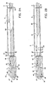
- Figure 1 schematically shows a first embodiment of a splicer according to the invention, and
- Figure 2A, B, C, D schematically show a second embodiment of a splicer according to the invention.
- Figure 1 schematically shows a top view of a first embodiment of a
splicer 1 for splicing strips of in rubber material embedded cords to each other according to the invention. The in the rubber material embedded cords may for instance be of steel or the like. Such cords reinforce the strips. - The
splicer 1 comprises asupply transport device 2 for supplying strips in asupply direction 3. According to the invention thesupply transport device 2 comprises afirst transport unit 4 and asecond transport unit 5 that are in line with each other. Thesecond transport unit 5 has aninlet end 9 and anoutlet end 10. - Furthermore the
splicer 1 comprises a splicing unit 6 for splicing strips to each other. The splicing unit 6 comprises a splicing table 7 and a splicing machine 8 placed over the splicing table 7. Asplice line 12 is determined by the splicing machine 8. - During operation of the
splicer 1 thefirst transport unit 4 supplies strips to thesecond transport unit 5. Thesecond transport unit 5 subsequently transports the strips further to the splicing table 7 of the splicing unit 6. - According to the invention the position of a strip to be supplied to the splicing table 7 can be adjusted to the position of a strip that is already present on the splicing table 7, so that these two strips can be spliced to each other more accurately, because the
outlet end 10 of thesecond transport unit 5 and the splicing table 7 are laterally, that means transverse to the transport direction, movable with respect to each other. - When the two strip have been spliced to each other, they are discharged by means of a
discharge transport device 11 for discharging strips spliced together. - For laterally moving the
outlet end 10 of thesecond transport unit 5 and the splicing table 7 with respect to each other, different alternatives are possible. For instance thesecond transport unit 5 can be laterally movable in its entirety. Additionally the second transport unit can be rotatably mounted around itsinlet end 9. Additionally or alternatively the splicing table 7 can be laterally movable in its entirety. - In order to transport the strip to a predetermined position on the splicing table 7, according to the invention a
first sensor 13 is provided for determining the centre of the strip between thefirst transport unit 4 and thesecond transport unit 5. Saidsensor 13 generates a starting position signal. In this way a strip can already be positioned at a very early stage, which increases the accuracy of the final splice. - Preferably a
second sensor 14 determines the position of the strip between thesecond transport unit 5 and the splicing table 7. Saidsecond sensor 14 also generates a middle position signal. Athird sensor 15 determines the position of the strip under thesplice line 12 and also generates an end position signal. As a result last-minute position alterations can be made, as will be explained below. - Preferably a computer is provided (not shown) having a file in which a target position has been included, and a comparer for comparing a position signal generated by one of the sensors and fed into the computer, with the target position and for issuing a control signal for controlling the relative lateral position of the splicing table 7 and/or the
second transport unit 5, as will be elucidated below. In a computer controlled manner the position of the splicing table 7 and/or thesecond transport unit 5 can thus be set. - A very accurate splice can be obtained when the target position is the centre of the
splice line 12. Especially in case of narrow and/or limp strips it is extra advantageous when the splicing machine 8 is rotatably mounted, and the point of rotation is formed by the middle of thesplice line 12. As discussed above, in this way possible deviations are distributed over both sides of the strips and the resulting (halved) deviations are acceptable indeed. - The invention also offers the possibility to reduce inaccuracies in the positioning as a result of sliding the strips over the splicing table 7, as shown in figure 2. The splicing table 7 has an imaginary
longitudinal centre line 16 dividing the splicing table 7 in a firstsplicing table half 17 and a secondsplicing table half 18. The splicing table 7 further has aninlet end 19 and anoutlet end 20. A first splicingtable transport unit 21 is placed on the firstsplicing table half 17, and extends from theinlet end 19 of the splicing table 7 up to a distance from theinlet end 19 of the splicing table 7. Because of this, half of a supplied strip can be placed on the first splicingtable transport unit 21, and for instance by synchronised drive with thesecond transport unit 5 the strip can be supplied in position on the splicing table 7 without loss of accuracy. - When after two strips have been spliced together they have to be discharged from the table, it is additionally advantageous when a second splicing
table transport unit 22 has been placed on the secondsplicing table half 18, and extends from the outlet end 20 of the splicing table 7 up to a distance therefrom. - The above-mentioned transport units and the like are for instance formed by conveyor belts, possibly provided with means for generating a vacuum or a magnetic field for transporting the strips slip-free.
- The
conveyor belts sensors - The operation of the splicer according to the invention will be elucidated below on the basis of the figures 2A-2D.
- During supplying a
strip 30 to the splicing table 7, thestrip 30 is laterally actively directed towards the target position on thesplice line 12. To that end the position of thestrip 30 is measured beforehand by thesensor 13 at the location where thestrip 30 is transferred on thesecond transport unit 5, also called centring conveyor. This offers the opportunity to direct the leading tip 31 (figure 2B) to the lateral target position during transport of thestrip 30 to the splicing table 7. In the same way the lateral position of the rear side of thestrip 30 is also measured during transfer to thecentring conveyor 5, and directed towards the target position during transport. - The stop position of the
strip 30 on the splicing table 7 is controlled by thesensors 14 and 15 (for clarity's sake only shown in figure 2A), on the basis of which data the drive of theconveyor belt 4 and the discharge transport device for discharging the strips spliced together is regulated. - In order to discharge the strips spliced together from the
splice line 12 while monitored and to supply a suppliedstrip 30 from thesplice line 12 while monitored, splicingtable transport units - During supply the splicing
table transport unit 21 preferably moves synchronously withcentring conveyor 5, and half of thestrip 30, as seen in transverse direction, is retained by the splicingtable transport unit 21. The other half of the strip to be supplied slides over the splicing table 7. - After splicing the
strip 30 to astrip 40 already supplied to the splicing table 7, thestrips transport units strip 30 takes place by means of thetransport unit 22. - Although it is shown in the figures that the splicing
table transport units table transport unit 21 needs to have sufficient clamping force to supply the material slip-free, whereas the second half has to be able to run under the already passedstrip 40, without the strip position being changed. To that end means for generating a vacuum of magnetic field for retaining the strip may be provided in the first part, and a so-called air-floatation system may be provided in the second part. With regard to the splicingtable transport unit 22 the placing of the means for generating a vacuum or magnetic field and the air-floatation system is the other way round. - In figure 2A a previous splice has already been made between strips, and the passing on of the strip starts at high speed by means of
conveyor belts tip 31 of thestrip 30 is measured by thesensor 13. As a result the centre line of thestrip 30 can be laid on the middle position of thesplice line 12. During passing on, the centre line of theend 42 of thestrip 40 already spliced together is directed towards the middle of thesplice line 12 by means of amovement device 43 connected to the centring conveyor 5 (for clarity's sake only shown in figure 2B). This treatment is finished when theend 42 leaves thecentring conveyor 5. Saidend 42 is perceived by thesensor 14. - In the situation shown in figure 2B the deceleration of the
strip 40 towards thesplice line 12 starts by means of the splicingtable transport units centring conveyor 5 is used to position the centre line of the arrivingtip 31 laterally, whereas saidconveyor 5 still works at high speed. As a result thetip 31 is directed exactly in the direction towards the middle of the splicing table 7, even before thetip 31 has reached the splicing table 7. - In figure 2C the situation is shown in which by means of the
sensor 15 the position of thestrip 40 is determined again. The splicetable transport units conveyor 5 decelerates to speed zero as well. Because of the low speed the measuring accuracy of the position of theend 42 with respect to thesplice line 12 is large as well, and the passed onend 42 can be positioned exactly towards the splicing position. The moment in which thesensor 15 no longer detects material is also the moment in which the speed of the splicingtable transport unit 21 is adjusted to the one of thecentring conveyor 5. - In figure 2D the situation is described in which the supplied
strip 30 is detected by thesensor 14. The splicingtable transport units strip 30 towards the stop position. When material is detected by thesensor 15 during the deceleration, the positioning may be adjusted. Meanwhile the lateral position of the trailing end 32 (see figure 2D) has been measured by thesensor 13, and thus its centre line as well can exactly be directed towards the middle of the splicing table 7. - Thus the lateral positioning of both the arriving and the already passed on tips and the ends of the strips, respectively, is carried out during transport over the centring
conveyor 5, which is not detrimental to the cycle time of the splicing unit. Moreover, both the lateral and the length position of the strips to be spliced are controlled up to the splice line by the splicingtable transport units
Claims (13)
- Splicing unit (6) for splicing strips (30) of in rubber material embedded cords to each other, which splicing unit comprises a splicing table (7) and a splicing machine (8) placed over the splicing table and determining a splice-line, said splicing table (7) being provided with an imaginary longitudinal axial line (16) dividing the splicing table in a first splicing table half (17) and a second splicing table half (18), an inlet end (19), an outlet end (20), a first splicing table transport unit (21) placed on the first splicing table half (17), characterized in that said first splicing table transport unit extends from the inlet end (19) of the splicing table (7) up to a distance from the inlet end (19) of the splicing table (7)
- Splicing unit according to claim 1, characterized in that the splicing unit (6) further comprises a second splicing table transport unit (22) placed on the second splicing table half (18), which second splicing table transport unit (22) extends from the outlet end (20) of the splicing table (7).
- Splicing unit according to claim 2, characterized in that the first splicing table transport unit (21) and the second splicing table transport unit (22) comprise a synchronised drive.
- Splicing unit according to claims 2 or 3, characterized in that the first and second splicing table transport units (21, 22) partially extend in longitudinal direction over the splicing table (7).
- Splicing unit according to claim 4, characterized in that that the first and second splicing table transport units (21, 22) extend in longitudinal direction over the splicing table (7), ending at a distance from one another, preferably both ending before the splice line.
- Splicing unit according to claims 2 or 3, characterized in that the first and second splicing table transport units (21, 22) extend in longitudinal direction over the entire length of the splicing table (7).
- Splicing unit according to claims 2-6, characterized in that the first and second splicing table transport units (21, 22) comprise means for providing a clamping force, sufficient to supply the strips slip-free, preferably the means are means for generating a vacuum or magnetic field.
- Splicing unit according to claim 6 or claim 7 when dependent from claim 6, characterized in that the second half of the first splicing table transport unit (21) comprises an air-floatation system for allowing the splicing table transport unit to run under an already passed strip without changing its position.
- Splicing unit according to any one of the preceding claims 2-8, characterized in that the first and second splicing table transport units (21, 22) comprise conveyor belts.
- Splicing unit according to any one of the preceding claims, characterized in that there is provided a sensor which is capable of determining the position of the strip under the splice line and which is capable of generating an end position signal.
- Splicing unit according to claims 2-10, characterized in that the first and second splicing table transport units are capable of decelerating in a synchronized manner to a speed zero, so that splicing the strips to each other takes place with motionless strips.
- Method for splicing strips (30) of in rubber material embedded cords to each other, using a splicing unit according to any one of the preceding claims 1-11, wherein the end tip (42) of a discharged strip (40) is spliced to the leading tip (31) of a supplied strip (30) characterized in- positioning the leading tip (31) of the supplied strip (30) by means of first splicing table transport unit (21) while monitoring its position using a sensor (15).
- Method according to claim 12, wherein the splicing unit (6) further comprises a second splicing table transport unit (22) placed on the second splicing table half (18), which second splicing table transport unit (22) extends from the outlet end (20) of the splicing table (7),
characterised in- first positioning the end tip (42) of the discharged strip (40) by means of the second splicing table transport unit (22) with respect to the splice line while monitoring its position using the sensor;- subsequently positioning the leading tip (31) of the supplied strip (30) while retaining the end tip (42) of the discharged strip (40) in its position on the first splicing table transport unit (21)
Applications Claiming Priority (3)
| Application Number | Priority Date | Filing Date | Title |
|---|---|---|---|
| NL1015250A NL1015250C2 (en) | 2000-05-19 | 2000-05-19 | Welding device for welding strips of cords embedded in rubber material together. |
| NL1015250 | 2000-05-19 | ||
| EP01932414A EP1282505B1 (en) | 2000-05-19 | 2001-05-21 | Splicer for splicing strips of cords embedded in rubber material |
Related Parent Applications (2)
| Application Number | Title | Priority Date | Filing Date |
|---|---|---|---|
| EP01932414.4 Division | 2001-05-21 | ||
| EP01932414A Division EP1282505B1 (en) | 2000-05-19 | 2001-05-21 | Splicer for splicing strips of cords embedded in rubber material |
Publications (3)
| Publication Number | Publication Date |
|---|---|
| EP1422047A2 EP1422047A2 (en) | 2004-05-26 |
| EP1422047A3 EP1422047A3 (en) | 2005-07-13 |
| EP1422047B1 true EP1422047B1 (en) | 2007-08-29 |
Family
ID=19771410
Family Applications (2)
| Application Number | Title | Priority Date | Filing Date |
|---|---|---|---|
| EP04075368A Expired - Lifetime EP1422047B1 (en) | 2000-05-19 | 2001-05-21 | Splicer for splicing strips of rubber with embedded cords |
| EP01932414A Expired - Lifetime EP1282505B1 (en) | 2000-05-19 | 2001-05-21 | Splicer for splicing strips of cords embedded in rubber material |
Family Applications After (1)
| Application Number | Title | Priority Date | Filing Date |
|---|---|---|---|
| EP01932414A Expired - Lifetime EP1282505B1 (en) | 2000-05-19 | 2001-05-21 | Splicer for splicing strips of cords embedded in rubber material |
Country Status (11)
| Country | Link |
|---|---|
| US (2) | US6796354B2 (en) |
| EP (2) | EP1422047B1 (en) |
| JP (2) | JP3953818B2 (en) |
| KR (1) | KR100777995B1 (en) |
| CN (1) | CN1208179C (en) |
| AU (1) | AU2001258941A1 (en) |
| DE (2) | DE60130268T2 (en) |
| NL (1) | NL1015250C2 (en) |
| RU (1) | RU2272778C2 (en) |
| SK (1) | SK16422002A3 (en) |
| WO (1) | WO2001089813A1 (en) |
Families Citing this family (8)
| Publication number | Priority date | Publication date | Assignee | Title |
|---|---|---|---|---|
| NL1022246C2 (en) * | 2002-12-23 | 2004-06-24 | Vmi Epe Holland | Device and method for making a belt layer. |
| KR101140074B1 (en) * | 2004-03-18 | 2012-04-30 | 브이엠아이 홀랜드 비.브이. | Cutting tool |
| US7441318B2 (en) * | 2005-02-09 | 2008-10-28 | The Goodyear Tire & Rubber Co | Method for detecting exposed metal cords in an elastomeric strip |
| US7497241B2 (en) | 2005-07-27 | 2009-03-03 | The Steelastic Company, Llc | Tire belt machine |
| NL2005819C2 (en) * | 2010-12-06 | 2012-06-07 | Vmi Holland Bv | WELDING DEVICE AND METHOD FOR WELDING TOGETHER OF RUBBER MATERIAL. |
| NL2011764C2 (en) * | 2013-11-08 | 2015-05-11 | Vmi Holland Bv | Method for centering a tire component. |
| JP5802818B1 (en) * | 2014-10-29 | 2015-11-04 | 東芝産業機器システム株式会社 | Progressive processing method |
| JP6696538B2 (en) * | 2018-08-21 | 2020-05-20 | 横浜ゴム株式会社 | Tire manufacturing method, molding system, and tire |
Family Cites Families (26)
| Publication number | Priority date | Publication date | Assignee | Title |
|---|---|---|---|---|
| US1189724A (en) * | 1915-06-28 | 1916-07-04 | Morgan & Wright | Apparatus for and process of cutting and reeling tire fabric. |
| US1961725A (en) * | 1927-07-30 | 1934-06-05 | Morgan & Wright | Apparatus for manufacturing tires |
| US2850277A (en) * | 1955-10-20 | 1958-09-02 | Goodyear Tire & Rubber | Strip aligning apparatus |
| US2947057A (en) * | 1956-02-03 | 1960-08-02 | Plainfield Patents Corp | Flexible web reeling and guiding mechanisms |
| US3832261A (en) * | 1970-02-11 | 1974-08-27 | Firestone Tire & Rubber Co | Materials handling assembly |
| US3859152A (en) * | 1970-02-11 | 1975-01-07 | Firestone Tire & Rubber Co | Tire fabric cutter |
| JPS5056908A (en) * | 1973-09-14 | 1975-05-19 | ||
| DE2628887A1 (en) * | 1976-06-26 | 1977-12-29 | Metzeler Kautschuk | DEVICE FOR CONNECTING STEEL CORD INSERTS FOR VEHICLE TIRES |
| IT1134875B (en) * | 1980-12-23 | 1986-08-20 | Pirelli | EQUIPMENT FOR THE SUPPLY OF STRENGTHENING STRATIA IN THE MANUFACTURE OF TIRES |
| DE3113619C2 (en) * | 1981-04-03 | 1984-04-05 | G. O. Stumpf GmbH & Co KG, 7421 Mehrstetten | Device for edge control for a spreading machine |
| IT1201922B (en) * | 1981-08-31 | 1989-02-02 | Sumitomo Rubber Ind | APPARATUS FOR THE APPLICATION OF CASE CANVAS AND SIMILAR MATERIALS ON A TIRE COVER PACKING DRUM |
| JPS5855235A (en) * | 1981-09-29 | 1983-04-01 | Bridgestone Corp | Continuous splicing method for ribbonlike material and device thereof |
| JPS5859829A (en) * | 1981-10-06 | 1983-04-09 | Kobe Steel Ltd | Conveying and forming device for rubber sheet material |
| JPS61148037A (en) * | 1984-12-24 | 1986-07-05 | Yokohama Rubber Co Ltd:The | Automatic supply device of constituting material of tire in tire molding machine |
| JPS625844A (en) * | 1985-07-02 | 1987-01-12 | Toyo Tire & Rubber Co Ltd | Connecting device for rubber-covered core |
| US4961813A (en) * | 1988-05-26 | 1990-10-09 | The Uniroyal Goodrich Tire Company | Servicer for tire building machine |
| US4976807A (en) * | 1989-04-12 | 1990-12-11 | Mitsubishi Jukogyo Kabushiki Kaisha | Apparatus for sticking a metal cord strip |
| JPH064293B2 (en) * | 1989-12-21 | 1994-01-19 | 住友ゴム工業株式会社 | Band-shaped sheet molding method and molding apparatus |
| EP0480672B1 (en) * | 1990-10-11 | 1995-06-14 | Sumitomo Rubber Industries Limited | Apparatus and method of manufacture for a green tyre |
| US5131971A (en) * | 1991-01-14 | 1992-07-21 | Elia Gerardo P | Apparatus for making a reinforced fabric from a ribbon of uncured elastomeric material |
| US5514233A (en) * | 1993-02-16 | 1996-05-07 | Mitsubishi Jukogyo Kabushiki Kaisha | Auto-splice device |
| DE4430453C2 (en) * | 1994-08-27 | 1996-08-14 | Fischer Maschf Karl E | Splicer |
| IT1286171B1 (en) * | 1996-07-12 | 1998-07-07 | Bridgestone Firestone Tech | CONVEYOR GROUP OF STRIPS. |
| DE19707367C1 (en) * | 1997-02-25 | 1998-06-10 | Fischer Maschf Karl E | Splicing machine, especially for butt splicing of steel or textile cord strip |
| DE69815499T2 (en) * | 1997-11-10 | 2004-05-19 | The Yokohama Rubber Co., Ltd. | DEVICE AND METHOD FOR ALIGNING AND SPLITTING STRIP ELEMENTS |
| DE19938149C2 (en) * | 1999-08-16 | 2002-07-18 | Continental Ag | Feeding device for strip-shaped tire components |
-
2000
- 2000-05-19 NL NL1015250A patent/NL1015250C2/en not_active IP Right Cessation
-
2001
- 2001-05-21 EP EP04075368A patent/EP1422047B1/en not_active Expired - Lifetime
- 2001-05-21 CN CNB018114180A patent/CN1208179C/en not_active Expired - Fee Related
- 2001-05-21 AU AU2001258941A patent/AU2001258941A1/en not_active Abandoned
- 2001-05-21 JP JP2001586033A patent/JP3953818B2/en not_active Expired - Fee Related
- 2001-05-21 RU RU2002134172/12A patent/RU2272778C2/en not_active IP Right Cessation
- 2001-05-21 WO PCT/NL2001/000385 patent/WO2001089813A1/en active IP Right Grant
- 2001-05-21 DE DE60130268T patent/DE60130268T2/en not_active Expired - Fee Related
- 2001-05-21 KR KR1020027015588A patent/KR100777995B1/en not_active IP Right Cessation
- 2001-05-21 EP EP01932414A patent/EP1282505B1/en not_active Expired - Lifetime
- 2001-05-21 DE DE60101962T patent/DE60101962T2/en not_active Expired - Fee Related
- 2001-05-21 SK SK1642-2002A patent/SK16422002A3/en unknown
-
2002
- 2002-11-15 US US10/298,260 patent/US6796354B2/en not_active Expired - Fee Related
-
2004
- 2004-04-14 US US10/823,978 patent/US20040188003A1/en not_active Abandoned
-
2007
- 2007-01-15 JP JP2007005594A patent/JP2007125895A/en not_active Withdrawn
Also Published As
| Publication number | Publication date |
|---|---|
| CN1437529A (en) | 2003-08-20 |
| EP1282505B1 (en) | 2004-02-04 |
| US6796354B2 (en) | 2004-09-28 |
| WO2001089813A1 (en) | 2001-11-29 |
| DE60130268D1 (en) | 2007-10-11 |
| DE60101962D1 (en) | 2004-03-11 |
| EP1422047A2 (en) | 2004-05-26 |
| DE60101962T2 (en) | 2004-10-28 |
| CN1208179C (en) | 2005-06-29 |
| JP2003534158A (en) | 2003-11-18 |
| NL1015250C2 (en) | 2001-11-22 |
| AU2001258941A1 (en) | 2001-12-03 |
| JP2007125895A (en) | 2007-05-24 |
| US20040188003A1 (en) | 2004-09-30 |
| JP3953818B2 (en) | 2007-08-08 |
| DE60130268T2 (en) | 2008-05-21 |
| KR100777995B1 (en) | 2007-11-27 |
| RU2272778C2 (en) | 2006-03-27 |
| SK16422002A3 (en) | 2003-05-02 |
| KR20030017975A (en) | 2003-03-04 |
| US20030089459A1 (en) | 2003-05-15 |
| EP1282505A1 (en) | 2003-02-12 |
| EP1422047A3 (en) | 2005-07-13 |
Similar Documents
| Publication | Publication Date | Title |
|---|---|---|
| CN105682912B (en) | Method for tyre element of feeling relieved | |
| KR101140074B1 (en) | Cutting tool | |
| US6280556B1 (en) | Apparatus and method for aligning and splicing strip members | |
| JP4509111B2 (en) | Tread pasting device | |
| US20090126874A1 (en) | Supply device for a tire-building drum | |
| US5175930A (en) | Method and apparatus for attaching belt-shaped member to forming drum | |
| KR20110015542A (en) | Device for manufacturing a pre-assembly for a tyre | |
| EP1422047B1 (en) | Splicer for splicing strips of rubber with embedded cords | |
| EA015088B1 (en) | Apparatus for connecting tubular cores | |
| CA1204794A (en) | Centering apparatus | |
| US4874443A (en) | Method for applying elastomeric material onto a drum | |
| EP1313607B1 (en) | Splicer for splicing strips of in rubber material embedded cords to each other | |
| US4902372A (en) | Innerliner applicator | |
| CA1211354A (en) | Length correct apparatus | |
| EP0104303A2 (en) | Innerliner applicator | |
| JPH0584849A (en) | Method for automatically supplying and bonding strip like material | |
| KR200351470Y1 (en) | Carcass suppling device of tire shaping drum | |
| CN218197083U (en) | Dual tire component feeder for supplying a first tire component and a second tire component to a tire building drum | |
| JP4167003B2 (en) | Cutting method of vulcanized tread member | |
| CN112512946B (en) | Sheet supply device and sheet supply method | |
| JPH01176546A (en) | Method and apparatus for centering belt material | |
| KR20000058243A (en) | Unit to control band transfer state of edge banders |
Legal Events
| Date | Code | Title | Description |
|---|---|---|---|
| PUAI | Public reference made under article 153(3) epc to a published international application that has entered the european phase |
Free format text: ORIGINAL CODE: 0009012 |
|
| AC | Divisional application: reference to earlier application |
Ref document number: 1282505 Country of ref document: EP Kind code of ref document: P |
|
| AK | Designated contracting states |
Kind code of ref document: A2 Designated state(s): DE FR GB IT NL |
|
| PUAL | Search report despatched |
Free format text: ORIGINAL CODE: 0009013 |
|
| AK | Designated contracting states |
Kind code of ref document: A3 Designated state(s): DE FR GB IT NL |
|
| 17P | Request for examination filed |
Effective date: 20060105 |
|
| AKX | Designation fees paid |
Designated state(s): DE FR GB IT NL |
|
| 17Q | First examination report despatched |
Effective date: 20060317 |
|
| GRAP | Despatch of communication of intention to grant a patent |
Free format text: ORIGINAL CODE: EPIDOSNIGR1 |
|
| GRAS | Grant fee paid |
Free format text: ORIGINAL CODE: EPIDOSNIGR3 |
|
| GRAA | (expected) grant |
Free format text: ORIGINAL CODE: 0009210 |
|
| AC | Divisional application: reference to earlier application |
Ref document number: 1282505 Country of ref document: EP Kind code of ref document: P |
|
| AK | Designated contracting states |
Kind code of ref document: B1 Designated state(s): DE FR GB IT NL |
|
| REG | Reference to a national code |
Ref country code: GB Ref legal event code: FG4D |
|
| REF | Corresponds to: |
Ref document number: 60130268 Country of ref document: DE Date of ref document: 20071011 Kind code of ref document: P |
|
| ET | Fr: translation filed | ||
| PLBE | No opposition filed within time limit |
Free format text: ORIGINAL CODE: 0009261 |
|
| STAA | Information on the status of an ep patent application or granted ep patent |
Free format text: STATUS: NO OPPOSITION FILED WITHIN TIME LIMIT |
|
| PGFP | Annual fee paid to national office [announced via postgrant information from national office to epo] |
Ref country code: DE Payment date: 20080419 Year of fee payment: 8 |
|
| 26N | No opposition filed |
Effective date: 20080530 |
|
| PGFP | Annual fee paid to national office [announced via postgrant information from national office to epo] |
Ref country code: IT Payment date: 20080526 Year of fee payment: 8 |
|
| PGFP | Annual fee paid to national office [announced via postgrant information from national office to epo] |
Ref country code: NL Payment date: 20080530 Year of fee payment: 8 |
|
| PGFP | Annual fee paid to national office [announced via postgrant information from national office to epo] |
Ref country code: GB Payment date: 20080521 Year of fee payment: 8 |
|
| GBPC | Gb: european patent ceased through non-payment of renewal fee |
Effective date: 20090521 |
|
| NLV4 | Nl: lapsed or anulled due to non-payment of the annual fee |
Effective date: 20091201 |
|
| PG25 | Lapsed in a contracting state [announced via postgrant information from national office to epo] |
Ref country code: NL Free format text: LAPSE BECAUSE OF NON-PAYMENT OF DUE FEES Effective date: 20091201 |
|
| REG | Reference to a national code |
Ref country code: FR Ref legal event code: ST Effective date: 20100129 |
|
| PG25 | Lapsed in a contracting state [announced via postgrant information from national office to epo] |
Ref country code: FR Free format text: LAPSE BECAUSE OF NON-PAYMENT OF DUE FEES Effective date: 20090602 |
|
| PGFP | Annual fee paid to national office [announced via postgrant information from national office to epo] |
Ref country code: FR Payment date: 20080429 Year of fee payment: 8 |
|
| PG25 | Lapsed in a contracting state [announced via postgrant information from national office to epo] |
Ref country code: GB Free format text: LAPSE BECAUSE OF NON-PAYMENT OF DUE FEES Effective date: 20090521 |
|
| PG25 | Lapsed in a contracting state [announced via postgrant information from national office to epo] |
Ref country code: DE Free format text: LAPSE BECAUSE OF NON-PAYMENT OF DUE FEES Effective date: 20091201 |
|
| PG25 | Lapsed in a contracting state [announced via postgrant information from national office to epo] |
Ref country code: IT Free format text: LAPSE BECAUSE OF NON-PAYMENT OF DUE FEES Effective date: 20090521 |