EP1422043A1 - Method of producing thermoplastic polycarbonate films having low optical retardation values - Google Patents
Method of producing thermoplastic polycarbonate films having low optical retardation values Download PDFInfo
- Publication number
- EP1422043A1 EP1422043A1 EP03026028A EP03026028A EP1422043A1 EP 1422043 A1 EP1422043 A1 EP 1422043A1 EP 03026028 A EP03026028 A EP 03026028A EP 03026028 A EP03026028 A EP 03026028A EP 1422043 A1 EP1422043 A1 EP 1422043A1
- Authority
- EP
- European Patent Office
- Prior art keywords
- die
- thermoplastic polycarbonate
- speed ratio
- nip
- rolls
- Prior art date
- Legal status (The legal status is an assumption and is not a legal conclusion. Google has not performed a legal analysis and makes no representation as to the accuracy of the status listed.)
- Granted
Links
Images


Classifications
-
- B—PERFORMING OPERATIONS; TRANSPORTING
- B29—WORKING OF PLASTICS; WORKING OF SUBSTANCES IN A PLASTIC STATE IN GENERAL
- B29D—PRODUCING PARTICULAR ARTICLES FROM PLASTICS OR FROM SUBSTANCES IN A PLASTIC STATE
- B29D7/00—Producing flat articles, e.g. films or sheets
- B29D7/01—Films or sheets
-
- B—PERFORMING OPERATIONS; TRANSPORTING
- B29—WORKING OF PLASTICS; WORKING OF SUBSTANCES IN A PLASTIC STATE IN GENERAL
- B29C—SHAPING OR JOINING OF PLASTICS; SHAPING OF MATERIAL IN A PLASTIC STATE, NOT OTHERWISE PROVIDED FOR; AFTER-TREATMENT OF THE SHAPED PRODUCTS, e.g. REPAIRING
- B29C43/00—Compression moulding, i.e. applying external pressure to flow the moulding material; Apparatus therefor
- B29C43/22—Compression moulding, i.e. applying external pressure to flow the moulding material; Apparatus therefor of articles of indefinite length
- B29C43/24—Calendering
-
- B—PERFORMING OPERATIONS; TRANSPORTING
- B29—WORKING OF PLASTICS; WORKING OF SUBSTANCES IN A PLASTIC STATE IN GENERAL
- B29C—SHAPING OR JOINING OF PLASTICS; SHAPING OF MATERIAL IN A PLASTIC STATE, NOT OTHERWISE PROVIDED FOR; AFTER-TREATMENT OF THE SHAPED PRODUCTS, e.g. REPAIRING
- B29C48/00—Extrusion moulding, i.e. expressing the moulding material through a die or nozzle which imparts the desired form; Apparatus therefor
- B29C48/03—Extrusion moulding, i.e. expressing the moulding material through a die or nozzle which imparts the desired form; Apparatus therefor characterised by the shape of the extruded material at extrusion
- B29C48/07—Flat, e.g. panels
- B29C48/08—Flat, e.g. panels flexible, e.g. films
-
- B—PERFORMING OPERATIONS; TRANSPORTING
- B29—WORKING OF PLASTICS; WORKING OF SUBSTANCES IN A PLASTIC STATE IN GENERAL
- B29C—SHAPING OR JOINING OF PLASTICS; SHAPING OF MATERIAL IN A PLASTIC STATE, NOT OTHERWISE PROVIDED FOR; AFTER-TREATMENT OF THE SHAPED PRODUCTS, e.g. REPAIRING
- B29C48/00—Extrusion moulding, i.e. expressing the moulding material through a die or nozzle which imparts the desired form; Apparatus therefor
- B29C48/25—Component parts, details or accessories; Auxiliary operations
- B29C48/88—Thermal treatment of the stream of extruded material, e.g. cooling
- B29C48/911—Cooling
- B29C48/9135—Cooling of flat articles, e.g. using specially adapted supporting means
- B29C48/914—Cooling of flat articles, e.g. using specially adapted supporting means cooling drums
-
- B—PERFORMING OPERATIONS; TRANSPORTING
- B29—WORKING OF PLASTICS; WORKING OF SUBSTANCES IN A PLASTIC STATE IN GENERAL
- B29C—SHAPING OR JOINING OF PLASTICS; SHAPING OF MATERIAL IN A PLASTIC STATE, NOT OTHERWISE PROVIDED FOR; AFTER-TREATMENT OF THE SHAPED PRODUCTS, e.g. REPAIRING
- B29C48/00—Extrusion moulding, i.e. expressing the moulding material through a die or nozzle which imparts the desired form; Apparatus therefor
- B29C48/25—Component parts, details or accessories; Auxiliary operations
- B29C48/88—Thermal treatment of the stream of extruded material, e.g. cooling
- B29C48/911—Cooling
- B29C48/9135—Cooling of flat articles, e.g. using specially adapted supporting means
- B29C48/915—Cooling of flat articles, e.g. using specially adapted supporting means with means for improving the adhesion to the supporting means
- B29C48/9155—Pressure rollers
-
- B—PERFORMING OPERATIONS; TRANSPORTING
- B29—WORKING OF PLASTICS; WORKING OF SUBSTANCES IN A PLASTIC STATE IN GENERAL
- B29C—SHAPING OR JOINING OF PLASTICS; SHAPING OF MATERIAL IN A PLASTIC STATE, NOT OTHERWISE PROVIDED FOR; AFTER-TREATMENT OF THE SHAPED PRODUCTS, e.g. REPAIRING
- B29C48/00—Extrusion moulding, i.e. expressing the moulding material through a die or nozzle which imparts the desired form; Apparatus therefor
- B29C48/25—Component parts, details or accessories; Auxiliary operations
- B29C48/88—Thermal treatment of the stream of extruded material, e.g. cooling
- B29C48/918—Thermal treatment of the stream of extruded material, e.g. cooling characterized by differential heating or cooling
- B29C48/9185—Thermal treatment of the stream of extruded material, e.g. cooling characterized by differential heating or cooling in the direction of the stream of the material
-
- B—PERFORMING OPERATIONS; TRANSPORTING
- B29—WORKING OF PLASTICS; WORKING OF SUBSTANCES IN A PLASTIC STATE IN GENERAL
- B29C—SHAPING OR JOINING OF PLASTICS; SHAPING OF MATERIAL IN A PLASTIC STATE, NOT OTHERWISE PROVIDED FOR; AFTER-TREATMENT OF THE SHAPED PRODUCTS, e.g. REPAIRING
- B29C48/00—Extrusion moulding, i.e. expressing the moulding material through a die or nozzle which imparts the desired form; Apparatus therefor
- B29C48/25—Component parts, details or accessories; Auxiliary operations
- B29C48/92—Measuring, controlling or regulating
-
- B—PERFORMING OPERATIONS; TRANSPORTING
- B29—WORKING OF PLASTICS; WORKING OF SUBSTANCES IN A PLASTIC STATE IN GENERAL
- B29C—SHAPING OR JOINING OF PLASTICS; SHAPING OF MATERIAL IN A PLASTIC STATE, NOT OTHERWISE PROVIDED FOR; AFTER-TREATMENT OF THE SHAPED PRODUCTS, e.g. REPAIRING
- B29C2948/00—Indexing scheme relating to extrusion moulding
- B29C2948/92—Measuring, controlling or regulating
- B29C2948/92009—Measured parameter
- B29C2948/92085—Velocity
- B29C2948/92095—Angular velocity
-
- B—PERFORMING OPERATIONS; TRANSPORTING
- B29—WORKING OF PLASTICS; WORKING OF SUBSTANCES IN A PLASTIC STATE IN GENERAL
- B29C—SHAPING OR JOINING OF PLASTICS; SHAPING OF MATERIAL IN A PLASTIC STATE, NOT OTHERWISE PROVIDED FOR; AFTER-TREATMENT OF THE SHAPED PRODUCTS, e.g. REPAIRING
- B29C2948/00—Indexing scheme relating to extrusion moulding
- B29C2948/92—Measuring, controlling or regulating
- B29C2948/92009—Measured parameter
- B29C2948/92114—Dimensions
- B29C2948/92123—Diameter or circumference
-
- B—PERFORMING OPERATIONS; TRANSPORTING
- B29—WORKING OF PLASTICS; WORKING OF SUBSTANCES IN A PLASTIC STATE IN GENERAL
- B29C—SHAPING OR JOINING OF PLASTICS; SHAPING OF MATERIAL IN A PLASTIC STATE, NOT OTHERWISE PROVIDED FOR; AFTER-TREATMENT OF THE SHAPED PRODUCTS, e.g. REPAIRING
- B29C2948/00—Indexing scheme relating to extrusion moulding
- B29C2948/92—Measuring, controlling or regulating
- B29C2948/92009—Measured parameter
- B29C2948/92209—Temperature
-
- B—PERFORMING OPERATIONS; TRANSPORTING
- B29—WORKING OF PLASTICS; WORKING OF SUBSTANCES IN A PLASTIC STATE IN GENERAL
- B29C—SHAPING OR JOINING OF PLASTICS; SHAPING OF MATERIAL IN A PLASTIC STATE, NOT OTHERWISE PROVIDED FOR; AFTER-TREATMENT OF THE SHAPED PRODUCTS, e.g. REPAIRING
- B29C2948/00—Indexing scheme relating to extrusion moulding
- B29C2948/92—Measuring, controlling or regulating
- B29C2948/92009—Measured parameter
- B29C2948/92247—Optical properties
-
- B—PERFORMING OPERATIONS; TRANSPORTING
- B29—WORKING OF PLASTICS; WORKING OF SUBSTANCES IN A PLASTIC STATE IN GENERAL
- B29C—SHAPING OR JOINING OF PLASTICS; SHAPING OF MATERIAL IN A PLASTIC STATE, NOT OTHERWISE PROVIDED FOR; AFTER-TREATMENT OF THE SHAPED PRODUCTS, e.g. REPAIRING
- B29C2948/00—Indexing scheme relating to extrusion moulding
- B29C2948/92—Measuring, controlling or regulating
- B29C2948/92323—Location or phase of measurement
- B29C2948/92361—Extrusion unit
- B29C2948/92409—Die; Nozzle zone
-
- B—PERFORMING OPERATIONS; TRANSPORTING
- B29—WORKING OF PLASTICS; WORKING OF SUBSTANCES IN A PLASTIC STATE IN GENERAL
- B29C—SHAPING OR JOINING OF PLASTICS; SHAPING OF MATERIAL IN A PLASTIC STATE, NOT OTHERWISE PROVIDED FOR; AFTER-TREATMENT OF THE SHAPED PRODUCTS, e.g. REPAIRING
- B29C2948/00—Indexing scheme relating to extrusion moulding
- B29C2948/92—Measuring, controlling or regulating
- B29C2948/92323—Location or phase of measurement
- B29C2948/92447—Moulded article
-
- B—PERFORMING OPERATIONS; TRANSPORTING
- B29—WORKING OF PLASTICS; WORKING OF SUBSTANCES IN A PLASTIC STATE IN GENERAL
- B29C—SHAPING OR JOINING OF PLASTICS; SHAPING OF MATERIAL IN A PLASTIC STATE, NOT OTHERWISE PROVIDED FOR; AFTER-TREATMENT OF THE SHAPED PRODUCTS, e.g. REPAIRING
- B29C2948/00—Indexing scheme relating to extrusion moulding
- B29C2948/92—Measuring, controlling or regulating
- B29C2948/92504—Controlled parameter
- B29C2948/9258—Velocity
- B29C2948/9259—Angular velocity
-
- B—PERFORMING OPERATIONS; TRANSPORTING
- B29—WORKING OF PLASTICS; WORKING OF SUBSTANCES IN A PLASTIC STATE IN GENERAL
- B29C—SHAPING OR JOINING OF PLASTICS; SHAPING OF MATERIAL IN A PLASTIC STATE, NOT OTHERWISE PROVIDED FOR; AFTER-TREATMENT OF THE SHAPED PRODUCTS, e.g. REPAIRING
- B29C2948/00—Indexing scheme relating to extrusion moulding
- B29C2948/92—Measuring, controlling or regulating
- B29C2948/92504—Controlled parameter
- B29C2948/92609—Dimensions
-
- B—PERFORMING OPERATIONS; TRANSPORTING
- B29—WORKING OF PLASTICS; WORKING OF SUBSTANCES IN A PLASTIC STATE IN GENERAL
- B29C—SHAPING OR JOINING OF PLASTICS; SHAPING OF MATERIAL IN A PLASTIC STATE, NOT OTHERWISE PROVIDED FOR; AFTER-TREATMENT OF THE SHAPED PRODUCTS, e.g. REPAIRING
- B29C2948/00—Indexing scheme relating to extrusion moulding
- B29C2948/92—Measuring, controlling or regulating
- B29C2948/92504—Controlled parameter
- B29C2948/92704—Temperature
-
- B—PERFORMING OPERATIONS; TRANSPORTING
- B29—WORKING OF PLASTICS; WORKING OF SUBSTANCES IN A PLASTIC STATE IN GENERAL
- B29C—SHAPING OR JOINING OF PLASTICS; SHAPING OF MATERIAL IN A PLASTIC STATE, NOT OTHERWISE PROVIDED FOR; AFTER-TREATMENT OF THE SHAPED PRODUCTS, e.g. REPAIRING
- B29C2948/00—Indexing scheme relating to extrusion moulding
- B29C2948/92—Measuring, controlling or regulating
- B29C2948/92819—Location or phase of control
- B29C2948/92857—Extrusion unit
- B29C2948/92904—Die; Nozzle zone
-
- B—PERFORMING OPERATIONS; TRANSPORTING
- B29—WORKING OF PLASTICS; WORKING OF SUBSTANCES IN A PLASTIC STATE IN GENERAL
- B29C—SHAPING OR JOINING OF PLASTICS; SHAPING OF MATERIAL IN A PLASTIC STATE, NOT OTHERWISE PROVIDED FOR; AFTER-TREATMENT OF THE SHAPED PRODUCTS, e.g. REPAIRING
- B29C2948/00—Indexing scheme relating to extrusion moulding
- B29C2948/92—Measuring, controlling or regulating
- B29C2948/92819—Location or phase of control
- B29C2948/92923—Calibration, after-treatment or cooling zone
-
- B—PERFORMING OPERATIONS; TRANSPORTING
- B29—WORKING OF PLASTICS; WORKING OF SUBSTANCES IN A PLASTIC STATE IN GENERAL
- B29C—SHAPING OR JOINING OF PLASTICS; SHAPING OF MATERIAL IN A PLASTIC STATE, NOT OTHERWISE PROVIDED FOR; AFTER-TREATMENT OF THE SHAPED PRODUCTS, e.g. REPAIRING
- B29C43/00—Compression moulding, i.e. applying external pressure to flow the moulding material; Apparatus therefor
- B29C43/22—Compression moulding, i.e. applying external pressure to flow the moulding material; Apparatus therefor of articles of indefinite length
-
- B—PERFORMING OPERATIONS; TRANSPORTING
- B29—WORKING OF PLASTICS; WORKING OF SUBSTANCES IN A PLASTIC STATE IN GENERAL
- B29C—SHAPING OR JOINING OF PLASTICS; SHAPING OF MATERIAL IN A PLASTIC STATE, NOT OTHERWISE PROVIDED FOR; AFTER-TREATMENT OF THE SHAPED PRODUCTS, e.g. REPAIRING
- B29C43/00—Compression moulding, i.e. applying external pressure to flow the moulding material; Apparatus therefor
- B29C43/32—Component parts, details or accessories; Auxiliary operations
- B29C43/44—Compression means for making articles of indefinite length
- B29C43/46—Rollers
-
- B—PERFORMING OPERATIONS; TRANSPORTING
- B29—WORKING OF PLASTICS; WORKING OF SUBSTANCES IN A PLASTIC STATE IN GENERAL
- B29K—INDEXING SCHEME ASSOCIATED WITH SUBCLASSES B29B, B29C OR B29D, RELATING TO MOULDING MATERIALS OR TO MATERIALS FOR MOULDS, REINFORCEMENTS, FILLERS OR PREFORMED PARTS, e.g. INSERTS
- B29K2069/00—Use of PC, i.e. polycarbonates or derivatives thereof, as moulding material
-
- B—PERFORMING OPERATIONS; TRANSPORTING
- B29—WORKING OF PLASTICS; WORKING OF SUBSTANCES IN A PLASTIC STATE IN GENERAL
- B29K—INDEXING SCHEME ASSOCIATED WITH SUBCLASSES B29B, B29C OR B29D, RELATING TO MOULDING MATERIALS OR TO MATERIALS FOR MOULDS, REINFORCEMENTS, FILLERS OR PREFORMED PARTS, e.g. INSERTS
- B29K2995/00—Properties of moulding materials, reinforcements, fillers, preformed parts or moulds
- B29K2995/0018—Properties of moulding materials, reinforcements, fillers, preformed parts or moulds having particular optical properties, e.g. fluorescent or phosphorescent
- B29K2995/0031—Refractive
- B29K2995/0032—Birefringent
Definitions
- the present invention relates to a process of preparing thermoplastic polycarbonate films having low optical retardation values.
- the process of the present invention makes use of at least two elastomeric polymer surfaced rolls through which a molten thermoplastic polycarbonate extrudate is passed.
- the extrudate temperature, the roll speed ratio and the die-nip distance are each selected such that a thermoplastic polycarbonate film having an optical retardation value of less than or equal to 20 nm is formed.
- Silica based glass and quartz are often used in many optical and display applications, such as lenses, ophthalmic lenses, optical windows, optical filters and liquid crystal displays.
- Thermoplastic polycarbonate films offer the advantage of reduced weight and increased impact resistance over glass and quartz.
- thermoplastic polycarbonate films provide improved flexibility, relative to glass and quartz, in those applications requiring thin films (e.g., film thicknesses of less than 30 mils).
- Thermoplastic polycarbonate films however, often have undesirably high optical retardation values, e.g., greater than 20 nm, such as 100 nm or 1000 nm.
- High optical retardation values are associated with an increased level of internal stress within the thermoplastic polycarbonate film, which is believed to be due to increased polymer chain orientation. Increased levels of internal stress can result in undesirable dimensional changes in the film over time, and in particular under conditions of temperature fluctuation.
- increased optical retardation values are undesirable in those optical applications which make use of polarized light. Such applications include, but are not limited to liquid crystal displays and write / erase opto-magnetic discs.
- Thermoplastic polycarbonate films having low optical retardation values can be prepared for example by casting methods, in which the film is cast from an organic solvent mixture, e.g., halogenated solvents. Film casting methods are described, for example, in United States Patent No. 5,561,180. Film casting methods are generally undesirable due to environmental concerns associated with the use and disposal of organic solvents, particularly in the case of the large scale production of polycarbonate films, and associated high production costs.
- United States Patent No. 5,076,987 discloses a process for the production of optically isotropic extruded polycarbonate films having a path difference of less than 10 nm/mm.
- the process of the '987 patent involves calendering the polycarbonate film between an elastic roller and a high gloss steel roller.
- thermoplastic polycarbonate film comprising:
- thermoplastic polycarbonate polymer that is extruded in the method of the present invention may be selected from those known to the skilled artisan.
- Classes of thermoplastic polycarbonates that may be used in the present invention include, but are not limited to, thermoplastic aliphatic polycarbonates, thermoplastic aromatic polycarbonates, thermoplastic aliphatic polyester polycarbonates, thermoplastic aromatic polyester polycarbonates and combinations thereof.
- Preferred classes of thermoplastic polycarbonates include thermoplastic aromatic polycarbonates and thermoplastic aromatic polyester polycarbonates.
- a particularly preferred class of thermoplastic polycarbonates are the thermoplastic aromatic polycarbonates, e.g., thermoplastic aromatic polycarbonates prepared from bisphenols, such as 4,4'-isopropylidenediphenol (bisphenol A).
- Commercially available thermoplastic polycarbonates that may be used in the present invention include, for example, those from Bayer Corporation, e.g., MAKROLON® 3108 thermoplastic polycarbonate.
- a molten extrudate of thermoplastic polycarbonate is formed in an extruder having a terminal die.
- the extruder may be selected from those known to the skilled artisan, e.g., single screw, twin-screw co-rotating and twin-screw counter-rotating extruders that may be either oil heated or electric heated. Typically a single screw extruder having a series of separately controlled electrically heated zones is used.
- the terminal die may be configured to expel the molten extrudate directly out of the face of the die.
- the terminal die is configured to expel the molten extrudate out of the bottom of the die, such that it drops by means of gravity directly down into the nip of a pair of elastomeric-surfaced counter-rotating rolls positioned below the terminal die.
- the molten thermoplastic polycarbonate extrudate emerges from the terminal die of the extruder at a lower temperature value of 150°C, preferably 200°C and more preferably 243°C.
- the molten thermoplastic polycarbonate extrudate emerges from terminal die of the extruder at an upper temperature value of 400°C, preferably 350°C and more preferably 315°C.
- the molten thermoplastic polycarbonate extrudate emerging from the terminal die of the extruder may have a temperature range selected from any combination of these recited lower and upper temperature values, e.g., 150°C to 400°C, 200°C to 350°C and 243°C to 315°C.
- the temperature of the molten extrudate has an effect on the optical retardation value of the thermoplastic polycarbonate film produced according to the method of the present invention.
- the optical retardation value of the thermoplastic polycarbonate film With the die-nip distance and the roll speed ratio of the counter-rotating rolls each maintained constant, it has been found that as the molten extrudate temperature is increased, the optical retardation value of the thermoplastic polycarbonate film generally decreases. However, if the molten extrudate temperature is too high, thermal degradation of the polymer is more likely to occur.
- the molten extrudate Upon emerging from the die, the molten extrudate is passed between two counter-rotating rolls.
- the counter-rotating rolls each have an elastomeric polymer surface. While the counter-rotating rolls may be fabricated substantially from one or more elastomeric polymers, more typically they are fabricated from metal, and the metal surface of the rolls are covered with an elastomeric polymer.
- elastomeric polymer means a polymer having resilient properties, e.g., natural and synthetic rubbers. Rolls having elastomeric polymer surfaces are known to the skilled artisan, and may be fabricated in accordance with art-recognized methods, for example as described in United States Patent No. 4,368,240.
- the elastomeric polymer of the counter-rotating rolls may be selected from those known to the skilled-artisan.
- the elastomeric polymer of the rolls is selected from silicone rubber, polytetrafluoroethylene, polypropylene and combinations thereof.
- the elastomeric polymer is selected from silicone rubber.
- the elastomeric polymer surfaces of the counter-rotating rolls each independently have a surface roughness of less than 100 ⁇ m.
- the elastomeric polymer surfaces of the counter-rotating rolls each independently have a surface roughness of from 0.01 ⁇ m to 50 ⁇ m.
- each of the counter-rotating rolls has substantially the same surface roughness value, which is from 0.01 ⁇ m to 50 ⁇ m.
- the distance between the terminal die, more particularly where the molten extrudate emerges from the terminal die, and the nip of the co-rotating elastomeric polymer surfaced rolls is referred to herein as the die-nip distance.
- the die-nip distance is typically greater than 2.5 cm and less than 50 cm, and preferably greater than 4 cm and less than 12 cm. In a preferred embodiment, the die-nip distance is from 10 cm and 12 cm, e.g., 11.5 cm.
- the undesirably high optical retardation values are thought, at least in part, to be the result of gravity induced orientation, which can occur as the distance, through which the molten extrudate falls, is increased too much.
- the undesirably high optical retardation values are thought, at least in part, to be the result of an insufficient amount of time to allow the polymer chains to relax from an oriented state to a random state.
- the roll speed ratio of the counter-rotating rolls is also selected such that the resulting thermoplastic polycarbonate film has an optical retardation value of less than 20 nm.
- the roll speed ratio i.e., the ratio of the speed at which the rolls are turned, is selected such that the peripheral speed ratio of the rolls is substantially 1 : 1.
- the peripheral speed of the rolls can be determined by means of calculation (e.g., measuring the actual radius or diameter of the rolls), or by measuring the peripheral speed of the rollers directly (e.g., by means of a laser).
- peripheral counter-rotating roll speed ratios that deviate from substantially 1 : 1, result in the introduction of stresses into the forming film, and a corresponding increase in the optical retardation values of the final film.
- the counter-rotating rolls may be selected such that they have different diameters.
- the counter-rotating rolls are selected such that they have substantially the same diameters.
- small differences in diameter can result from the process by which the rolls are fabricated, or from differential wear during operation of the rolls. Even small deviations in the diameter of the rolls (e.g., a difference in diameter of from 0.01 cm to 0.20 cm between the rolls) have been found to result in films having undesirably high optical retardation values.
- the roll speed ratio is selected from 0.990 : 1.000 to 1.100 : 1.000, and preferably from 1.000 : 1.000 to 1.004 : 1.000.
- the thermoplastic polycarbonate film produced in accordance with the method of the present invention typically has an optical retardation value of less than 20 nm, preferably less than 15 nm and more preferably less than 10 nm.
- the optical retardation value of the film is equal to or greater than 0 nm (e.g., 0.01 nm) and less than 20 nm (e.g., a value of from 1 nm to 7 nm).
- low optical retardation values e.g., less than 20 nm
- Optical retardation values can be measured by means known to the skilled artisan, e.g., by means of an SCA-1500 Instrument from Strainoptic Technologies, Inc.
- the thermoplastic polycarbonate film typically has a film thickness of less than or equal to 1000 ⁇ m, e.g., from 50 ⁇ m to 1000 ⁇ m. Preferably, the thermoplastic polycarbonate film has a film thickness of 75 ⁇ m to 800 ⁇ m.
- Each surface of the thermoplastic polycarbonate film independently has a surface roughness value of from 0.01 to 50 ⁇ m. In an embodiment, each surface of the thermoplastic polycarbonate has substantially the same surface roughness value, which is from 0.01 to 50 ⁇ m.
- Thermoplastic polycarbonate feed typically in form of pellets (not shown), is fed into an extruder 11, by means of a feed port 14.
- Extruder 11 may be, as discussed previously herein, a single or twin-screw extruder, and typically has a series of separately controlled electrically heated zones (not shown) along the barrel.
- the thermoplastic polycarbonate feed is conveyed and melted at it passes through extruder 11 and emerges as a molten extrudate 20 from terminal die 17.
- Molten extrudate 20 drops from terminal die 17 into the nip 41 of counter-rotating rolls 23 and 26, the rotation of which is indicated by arcuate arrows 65 and 68.
- Counter-rotating rolls 23 and 26 each have an elastomeric polymer surface 35 and 38, e.g., of silicone rubber.
- the distance between the point 71 where molten extrudate 20 exits terminal die 17 and nip 41 is the die-nip distance 47.
- Molten extrudate 20 solidifies as it passes through nip 41 and around roll 26. Typically, the molten extrudate has substantially solidified into film 32 by the time is reaches nip 78 between roll 26 and optional take-up roll 29.
- Optional take-up roll 29 (which has a rotation counter to that of roll 26 as indicated by arcuate line 74) serves to take the thermoplastic film 32 off of roll 26. Take-up roll 29 may optionally have an elastomeric polymer surface (not shown), but typically has a polished metal surface. Thermoplastic polycarbonate film 32 is taken off of take-up roll 29 and propelled forward, as indicated by arrow 44, for further processing (e.g., cutting and/or trimming) or collection on a collection roll (not shown).
- the method comprises (with reference to Figure 3 of the drawings):
- Steps (d) and (e) can be performed periodically or continuously.
- steps (d) and (e) can be performed: manually; automatically (e.g., manually or by means of feed-back loop 5); or a combination of manually and automatically.
- the extrudate temperature and die-nip distance are maintained substantially constant, while the roll speed ratio is adjusted, e.g., either periodically or continuously.
- the film formation apparatus 3 is coupled with a feed-back loop 5, which includes an in-line optical retardation scanning instrument 50 that is digitally connected by means of data line 53 to a programmable controller 56.
- Programmable controller 56 is further connected by means of electrical lines 62 and 59 to counter-rotating rolls 23 and 26.
- Optical retardation data is taken periodically or continuously as film 32 passes by scanner 50.
- the optical retardation data is transmitted from scanner 50 to programmable controller 56 by means of data line 53.
- the optical retardation data is compared to preset values within controller 56.
- the roll speed ratio of rolls 23 and 26 are adjusted by means of electrical lines 62 and 59.
- the comparison of optical retardation data and adjustment of the roll speed ratios can be done periodically or continuously. In addition, such comparison and adjustment can be done manually in the absence of controller 56.
- programmable controller 56 can be attached to at least one of: rolls 23 and 26 (for purposes of adjusting the roll speed ratio); extruder 11 (for purposes of adjusting the temperature of the molten extrudate); and a means of elevating / lowering rolls 23 and 26, not shown (for purposes of adjusting die-nip distance 47). Controller 56 can be attached to extruder 11 and/or the means of elevating / lowering rolls 23 and 26 by means of additional electrical connections (not shown).
- thermoplastic polycarbonate films prepared in accordance with the method of the present invention may include additives, selected from, for example: light stabilizers, UV stabilizers, thermal stabilizers, antioxidants, dyes, waxes and combinations thereof.
- additives are typically present in amounts of less than 20 percent by weight, for example from 0.01 to 15 percent by weight, or 0.1 to 5 or 10 percent by weight, the percent weights being based on the weight of the thermoplastic polycarbonate film.
- the additives are typically incorporated into the film during the extrusion process, in accordance with art-recognized methods.
- thermoplastic polycarbonate films prepared in accordance with the method of the present invention may be used in many applications, including those requiring films having low optical retardation values, for example, liquid crystal displays, write / erase opto-magnetic discs.
- thermoplastic polycarbonate used was MAKROLON® 3108 thermoplastic polycarbonate, a bisphenol-A based polycarbonate commercially available from Bayer Corporation in pellet form, having a melt flow rate of 6.5 grams / 10 minutes (as determined at 300°C with a 1.2 kg load, in accordance with ASTM D 1238).
- An electrically heated single screw extruder having a screw diameter of 90 mm and an L/D ratio of 30, was used. The polycarbonate was fed into the extruder at a rate of 2.6 kg/minute.
- rolls 23 and 26 through which the molten extrudate 20 was passed, each had an elastomeric surface (35 and 38) of silicone rubber having a shore A hardness of 80 and a surface roughness value (Ra) of 10 ⁇ m.
- Each of rolls 23 and 26 had a diameter of approximately 203 mm.
- Rolls 23 and 26 were operated at a contact pressure of 0.4 MPa.
- Separate heat exchange fluid streams having temperatures of 32°C, 57°C and 140°C were continually pumped through each of rolls 23, 26 and 29 respectively. However the surface temperatures of rolls 23, 26 and 29 were not monitored.
- Both surfaces of the thermoplastic polycarbonate film produced in the following examples each had a surface roughness (Ra value) of 10 ⁇ m.
- Optical retardation values were determined using a SCA-1500 instrument system from Strainoptic Technologies, Inc., in accordance with the manufacturer's operating instructions. Optical retardation values are recited in units of nanometers (nm).
- thermoplastic polycarbonate film had a thickness of 127 ⁇ m.
- a roll speed ratio of from 1.002 to 1.004 results in desirable optical retardation values of approximately 15 nm. Roll speed ratios outside of this range result in undesirably high optical retardation values.
- the temperature of the molten polycarbonate extrudate 20 was 272°C, and the roll speed ratio of rolls 23 and 26 was 1.003.
- the extruded polycarbonate film 32 had a thickness of 250 ⁇ m. At a die-nip distance of 3.8 cm the optical retardation of the extruded polycarbonate film was 22 nm. At a die-nip distance of 11.5 cm, the optical retardation of the extruded polycarbonate film was 14 nm.
- thermoplastic polycarbonate film was extruded in accordance with the process of the present invention under the following conditions: molten polycarbonate extrudate temperature of 254°C; roll speed ratio of 1.003; and a die-nip distance of 11.5 cm.
- the extruded thermoplastic polycarbonate film had a thickness of 127 ⁇ m, and an optical retardation value of 5 nm.
Abstract
Description
- The present invention relates to a process of preparing thermoplastic polycarbonate films having low optical retardation values. The process of the present invention makes use of at least two elastomeric polymer surfaced rolls through which a molten thermoplastic polycarbonate extrudate is passed. In the process of the present invention, the extrudate temperature, the roll speed ratio and the die-nip distance are each selected such that a thermoplastic polycarbonate film having an optical retardation value of less than or equal to 20 nm is formed.
- Silica based glass and quartz are often used in many optical and display applications, such as lenses, ophthalmic lenses, optical windows, optical filters and liquid crystal displays. Thermoplastic polycarbonate films offer the advantage of reduced weight and increased impact resistance over glass and quartz. In particular, thermoplastic polycarbonate films provide improved flexibility, relative to glass and quartz, in those applications requiring thin films (e.g., film thicknesses of less than 30 mils).
- Thermoplastic polycarbonate films, however, often have undesirably high optical retardation values, e.g., greater than 20 nm, such as 100 nm or 1000 nm. High optical retardation values are associated with an increased level of internal stress within the thermoplastic polycarbonate film, which is believed to be due to increased polymer chain orientation. Increased levels of internal stress can result in undesirable dimensional changes in the film over time, and in particular under conditions of temperature fluctuation. In many optical applications, it is necessary that the films employed be dimensionally stable. In addition, increased optical retardation values are undesirable in those optical applications which make use of polarized light. Such applications include, but are not limited to liquid crystal displays and write / erase opto-magnetic discs.
- Thermoplastic polycarbonate films having low optical retardation values (i.e., low birefringence) can be prepared for example by casting methods, in which the film is cast from an organic solvent mixture, e.g., halogenated solvents. Film casting methods are described, for example, in United States Patent No. 5,561,180. Film casting methods are generally undesirable due to environmental concerns associated with the use and disposal of organic solvents, particularly in the case of the large scale production of polycarbonate films, and associated high production costs.
- United States Patent No. 5,076,987 discloses a process for the production of optically isotropic extruded polycarbonate films having a path difference of less than 10 nm/mm. The process of the '987 patent involves calendering the polycarbonate film between an elastic roller and a high gloss steel roller.
- In accordance with the present invention, there is provided a method of preparing a thermoplastic polycarbonate film comprising:
- (a) forming a molten extrudate of a thermoplastic polycarbonate polymer in an extruder having a terminal die through which said molten extrudate is passed, said molten extrudate having a temperature of 150°C to 400°C upon emerging from said terminal die;
- (b) passing the molten extrudate, from said die, between two counter-rotating rolls each having an elastomeric polymer surface, said counter-rotating rolls having a roll speed ratio and a nip, the distance between said terminal die and said nip being a die-nip distance; wherein the extrudate temperature, the roll speed ratio and the die-nip distance are each selected such that a thermoplastic polycarbonate film having an optical retardation value of less than or equal to 20 nm is formed.
-
- The features that characterize the present invention are pointed out with particularity in the claims, which are annexed to and form a part of this disclosure. These and other features of the invention, its operating advantages and the specific objects obtained by its use will be more fully understood from the following detailed description and accompanying drawings.
- Unless otherwise indicated, all numbers or expressions, such as those expressing structural dimensions, process conditions, quantities of ingredients, etc. used in the specification and claims are understood as modified in all instances by the term "about."
-
- Figure 1 is a schematic representation of an extrusion process of the present invention;
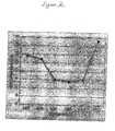
- Figure 2 (which is referred to in the Examples herein) is a graph showing a plot of optical retardation versus roll speed ratio in the extrusion formation of a thermoplastic polycarbonate film at substantially constant extrudate temperature and constant die-nip distance;
- Figure 3 is a schematic representation of an extrusion process according to the present invention that further includes a feedback loop whereby the roll speed ratio is adjusted in response to the in-line measurement of optical retardation values.
-
- In Figures 1 through 3, like reference numerals and characters designate the same components, structural features and process streams.
- The thermoplastic polycarbonate polymer that is extruded in the method of the present invention may be selected from those known to the skilled artisan. Classes of thermoplastic polycarbonates that may be used in the present invention include, but are not limited to, thermoplastic aliphatic polycarbonates, thermoplastic aromatic polycarbonates, thermoplastic aliphatic polyester polycarbonates, thermoplastic aromatic polyester polycarbonates and combinations thereof. Preferred classes of thermoplastic polycarbonates include thermoplastic aromatic polycarbonates and thermoplastic aromatic polyester polycarbonates. A particularly preferred class of thermoplastic polycarbonates are the thermoplastic aromatic polycarbonates, e.g., thermoplastic aromatic polycarbonates prepared from bisphenols, such as 4,4'-isopropylidenediphenol (bisphenol A). Commercially available thermoplastic polycarbonates that may be used in the present invention include, for example, those from Bayer Corporation, e.g., MAKROLON® 3108 thermoplastic polycarbonate.
- In the method of the present invention, a molten extrudate of thermoplastic polycarbonate is formed in an extruder having a terminal die. The extruder may be selected from those known to the skilled artisan, e.g., single screw, twin-screw co-rotating and twin-screw counter-rotating extruders that may be either oil heated or electric heated. Typically a single screw extruder having a series of separately controlled electrically heated zones is used. The terminal die may be configured to expel the molten extrudate directly out of the face of the die. Typically, the terminal die is configured to expel the molten extrudate out of the bottom of the die, such that it drops by means of gravity directly down into the nip of a pair of elastomeric-surfaced counter-rotating rolls positioned below the terminal die.
- The molten thermoplastic polycarbonate extrudate emerges from the terminal die of the extruder at a lower temperature value of 150°C, preferably 200°C and more preferably 243°C. The molten thermoplastic polycarbonate extrudate emerges from terminal die of the extruder at an upper temperature value of 400°C, preferably 350°C and more preferably 315°C. The molten thermoplastic polycarbonate extrudate emerging from the terminal die of the extruder may have a temperature range selected from any combination of these recited lower and upper temperature values, e.g., 150°C to 400°C, 200°C to 350°C and 243°C to 315°C.
- The temperature of the molten extrudate has an effect on the optical retardation value of the thermoplastic polycarbonate film produced according to the method of the present invention. With the die-nip distance and the roll speed ratio of the counter-rotating rolls each maintained constant, it has been found that as the molten extrudate temperature is increased, the optical retardation value of the thermoplastic polycarbonate film generally decreases. However, if the molten extrudate temperature is too high, thermal degradation of the polymer is more likely to occur.
- Upon emerging from the die, the molten extrudate is passed between two counter-rotating rolls. The counter-rotating rolls each have an elastomeric polymer surface. While the counter-rotating rolls may be fabricated substantially from one or more elastomeric polymers, more typically they are fabricated from metal, and the metal surface of the rolls are covered with an elastomeric polymer. As used herein and in the claims, the term "elastomeric polymer" means a polymer having resilient properties, e.g., natural and synthetic rubbers. Rolls having elastomeric polymer surfaces are known to the skilled artisan, and may be fabricated in accordance with art-recognized methods, for example as described in United States Patent No. 4,368,240.
- The elastomeric polymer of the counter-rotating rolls may be selected from those known to the skilled-artisan. In an embodiment of the present invention the elastomeric polymer of the rolls is selected from silicone rubber, polytetrafluoroethylene, polypropylene and combinations thereof. In a preferred embodiment of the present invention, the elastomeric polymer is selected from silicone rubber.
- The elastomeric polymer surfaces of the counter-rotating rolls each independently have a surface roughness of less than 100 µm. Preferably, the elastomeric polymer surfaces of the counter-rotating rolls each independently have a surface roughness of from 0.01 µm to 50 µm. In selecting elastomeric polymer surfaced rolls having different surface roughness values, it is possible to form films having a smooth or mirror-like surface on one side, and a matte or micro-matte surface on the other side. In an embodiment of the present invention, each of the counter-rotating rolls has substantially the same surface roughness value, which is from 0.01 µm to 50 µm.
- The distance between the terminal die, more particularly where the molten extrudate emerges from the terminal die, and the nip of the co-rotating elastomeric polymer surfaced rolls is referred to herein as the die-nip distance. The die-nip distance is typically greater than 2.5 cm and less than 50 cm, and preferably greater than 4 cm and less than 12 cm. In a preferred embodiment, the die-nip distance is from 10 cm and 12 cm, e.g., 11.5 cm.
- With the molten extrudate temperature and the roll speed ratio of the counter-rotating rolls each maintained constant, an increase in die-nip distance has been found to generally result in a decrease in the optical retardation values of the film. However, it has also been found that if the die-nip distance is too small (e.g., less than 2.5 cm) or too large (e.g., greater than 50 cm), the optical retardation values of the resulting film will be undesirably high (e.g., greater than 20 nm). In the case of large die-nip distances, and while not intending to be bound by any theory, the undesirably high optical retardation values are thought, at least in part, to be the result of gravity induced orientation, which can occur as the distance, through which the molten extrudate falls, is increased too much. In the case of die-nip distances that are too small, and while not intending to be bound by any theory, the undesirably high optical retardation values are thought, at least in part, to be the result of an insufficient amount of time to allow the polymer chains to relax from an oriented state to a random state.
- In addition to selecting the temperature of the molten extrudate and the die-nip distance, the roll speed ratio of the counter-rotating rolls is also selected such that the resulting thermoplastic polycarbonate film has an optical retardation value of less than 20 nm. Typically, the roll speed ratio, i.e., the ratio of the speed at which the rolls are turned, is selected such that the peripheral speed ratio of the rolls is substantially 1 : 1. The peripheral speed of the rolls can be determined by means of calculation (e.g., measuring the actual radius or diameter of the rolls), or by measuring the peripheral speed of the rollers directly (e.g., by means of a laser).
- While not intending to be bound by any theory, it is believed based on the evidence at hand, that peripheral counter-rotating roll speed ratios that deviate from substantially 1 : 1, result in the introduction of stresses into the forming film, and a corresponding increase in the optical retardation values of the final film. The counter-rotating rolls may be selected such that they have different diameters. Preferably, the counter-rotating rolls are selected such that they have substantially the same diameters. However, small differences in diameter can result from the process by which the rolls are fabricated, or from differential wear during operation of the rolls. Even small deviations in the diameter of the rolls (e.g., a difference in diameter of from 0.01 cm to 0.20 cm between the rolls) have been found to result in films having undesirably high optical retardation values. In an embodiment of the present invention, with counter-rotating rolls that have substantially the same diameter, the roll speed ratio is selected from 0.990 : 1.000 to 1.100 : 1.000, and preferably from 1.000 : 1.000 to 1.004 : 1.000.
- In a particularly preferred embodiment of the present invention:
- each counter-rotating roll has similar or substantially the same diameter, and the roll speed ratio is selected from 1.000 : 1.000 to 1.004 : 1.000 (such that the counter-rotating rolls have a peripheral speed of substantially 1 : 1); the molten extrudate has a temperature of 243°C to 315°C; and the die-nip distance is greater than 4 cm and less than 12 cm, particularly preferably the die-nip distance is 11.5 cm.
-
- The thermoplastic polycarbonate film produced in accordance with the method of the present invention typically has an optical retardation value of less than 20 nm, preferably less than 15 nm and more preferably less than 10 nm. In an embodiment of the present invention, the optical retardation value of the film is equal to or greater than 0 nm (e.g., 0.01 nm) and less than 20 nm (e.g., a value of from 1 nm to 7 nm). As discussed previously herein, low optical retardation values (e.g., less than 20 nm) are indicative of decreased or low levels of internal stress and decreased molecular chain orientation within the thermoplastic polycarbonate film, which is further indicative of films having a desirably high level of dimensional stability. Optical retardation values can be measured by means known to the skilled artisan, e.g., by means of an SCA-1500 Instrument from Strainoptic Technologies, Inc.
- The thermoplastic polycarbonate film typically has a film thickness of less than or equal to 1000 µm, e.g., from 50 µm to 1000 µm. Preferably, the thermoplastic polycarbonate film has a film thickness of 75 µm to 800 µm. Each surface of the thermoplastic polycarbonate film independently has a surface roughness value of from 0.01 to 50 µm. In an embodiment, each surface of the thermoplastic polycarbonate has substantially the same surface roughness value, which is from 0.01 to 50 µm.
- An embodiment of the method of the present invention will be described with reference to the
film formation apparatus 3 of Figure 1 of the drawings. Thermoplastic polycarbonate feed, typically in form of pellets (not shown), is fed into an extruder 11, by means of afeed port 14. Extruder 11 may be, as discussed previously herein, a single or twin-screw extruder, and typically has a series of separately controlled electrically heated zones (not shown) along the barrel. The thermoplastic polycarbonate feed is conveyed and melted at it passes through extruder 11 and emerges as amolten extrudate 20 from terminal die 17.Molten extrudate 20 drops from terminal die 17 into thenip 41 of counter-rotating rolls 23 and 26, the rotation of which is indicated byarcuate arrows 65 and 68. Counter-rotating rolls 23 and 26 each have anelastomeric polymer surface point 71 wheremolten extrudate 20 exits terminal die 17 and nip 41 is the die-nip distance 47. -
Molten extrudate 20 solidifies as it passes through nip 41 and aroundroll 26. Typically, the molten extrudate has substantially solidified intofilm 32 by the time is reaches nip 78 betweenroll 26 and optional take-up roll 29. Optional take-up roll 29 (which has a rotation counter to that ofroll 26 as indicated by arcuate line 74) serves to take thethermoplastic film 32 off ofroll 26. Take-up roll 29 may optionally have an elastomeric polymer surface (not shown), but typically has a polished metal surface.Thermoplastic polycarbonate film 32 is taken off of take-up roll 29 and propelled forward, as indicated byarrow 44, for further processing (e.g., cutting and/or trimming) or collection on a collection roll (not shown). - In an embodiment of the present invention, the method comprises (with reference to Figure 3 of the drawings):
- (a) forming a molten extrudate (20) of a thermoplastic polycarbonate polymer in an extruder (11) having a terminal die (17) through which said molten extrudate (20) is passed, said molten extrudate (20) having a temperature of 150°C to 400°C upon emerging from said terminal die (17);
- (b) passing the molten extrudate (20), from said die (17), between two counter-rotating rolls (23 and 26) each having an elastomeric polymer surface (35 and 38), said counter-rotating rolls (23 and 26) having a roll speed ratio and a nip (41), the distance between said terminal die and said nip (41) being a die-nip distance (47);
- (c) forwarding said thermoplastic polycarbonate film (32) from said counter-rotating rolls (23 and 26) as it is formed;
- (d) measuring optical retardation values of the forwarded thermoplastic polycarbonate film (e.g., by means of an optical retardation scanning instrument 50); and
- (e) adjusting at least one of the extrudate temperature, the roll speed ratio and the die-nip distance, such that the forwarded thermoplastic polycarbonate film (32) has an optical retardation value of less than or equal to 20 nm.
-
- Steps (d) and (e) can be performed periodically or continuously. In addition, steps (d) and (e) can be performed: manually; automatically (e.g., manually or by means of feed-back loop 5); or a combination of manually and automatically.
- In a preferred embodiment, as represented in Figure 3, the extrudate temperature and die-nip distance are maintained substantially constant, while the roll speed ratio is adjusted, e.g., either periodically or continuously. With further reference to Figure 3, the
film formation apparatus 3 is coupled with a feed-back loop 5, which includes an in-line opticalretardation scanning instrument 50 that is digitally connected by means ofdata line 53 to aprogrammable controller 56.Programmable controller 56 is further connected by means ofelectrical lines film 32 passes byscanner 50. The optical retardation data is transmitted fromscanner 50 toprogrammable controller 56 by means ofdata line 53. The optical retardation data is compared to preset values withincontroller 56. If the optical retardation values are too high, then the roll speed ratio ofrolls electrical lines controller 56. - In a further embodiment of the present invention,
programmable controller 56 can be attached to at least one of: rolls 23 and 26 (for purposes of adjusting the roll speed ratio); extruder 11 (for purposes of adjusting the temperature of the molten extrudate); and a means of elevating / loweringrolls Controller 56 can be attached to extruder 11 and/or the means of elevating / loweringrolls - The thermoplastic polycarbonate films prepared in accordance with the method of the present invention may include additives, selected from, for example: light stabilizers, UV stabilizers, thermal stabilizers, antioxidants, dyes, waxes and combinations thereof. Such additives are typically present in amounts of less than 20 percent by weight, for example from 0.01 to 15 percent by weight, or 0.1 to 5 or 10 percent by weight, the percent weights being based on the weight of the thermoplastic polycarbonate film. The additives are typically incorporated into the film during the extrusion process, in accordance with art-recognized methods.
- The thermoplastic polycarbonate films prepared in accordance with the method of the present invention may be used in many applications, including those requiring films having low optical retardation values, for example, liquid crystal displays, write / erase opto-magnetic discs.
- The present invention is more particularly described in the following examples , which are intended to be illustrative only, since numerous modifications and variations therein will be apparent to those skilled in the art. Unless otherwise specified, all parts and percentages are by weight.
- In the following examples the thermoplastic polycarbonate used was MAKROLON® 3108 thermoplastic polycarbonate, a bisphenol-A based polycarbonate commercially available from Bayer Corporation in pellet form, having a melt flow rate of 6.5 grams / 10 minutes (as determined at 300°C with a 1.2 kg load, in accordance with ASTM D 1238). An electrically heated single screw extruder having a screw diameter of 90 mm and an L/D ratio of 30, was used. The polycarbonate was fed into the extruder at a rate of 2.6 kg/minute.
- In the following examples an extruder /
roller configuration 3 similar to that depicted in Figure 1 was used. With reference to Figure 1, rolls 23 and 26, through which themolten extrudate 20 was passed, each had an elastomeric surface (35 and 38) of silicone rubber having a shore A hardness of 80 and a surface roughness value (Ra) of 10 µm. Each ofrolls Rolls Roll 29, upon whichfilm 32 was taken up off ofroll 26, had a polished stainless steel surface and a diameter of approximately 203 mm. Separate heat exchange fluid streams having temperatures of 32°C, 57°C and 140°C were continually pumped through each ofrolls rolls - Optical retardation values were determined using a SCA-1500 instrument system from Strainoptic Technologies, Inc., in accordance with the manufacturer's operating instructions. Optical retardation values are recited in units of nanometers (nm).
- The affect of roll speed ratio on the optical retardation values of an extruded thermoplastic polycarbonate film is demonstrated in the present example.
- With reference to Figure 1, the roll speed ratio of
rolls thermoplastic film 32. Samples of extruded polycarbonate film were collected and later analyzed to determine their optical retardation values. Throughout the evaluation, the temperature of themolten polycarbonate extrudate 20 was 271 °C, and the die-nip distance 47 was 11.5 cm. The optical retardation values of the polycarbonate film as a function of roll speed ratio were plotted, and is shown in Figure 2. The thermoplastic polycarbonate film had a thickness of 127 µm. - With reference to Figure 2, a roll speed ratio of from 1.002 to 1.004 results in desirable optical retardation values of approximately 15 nm. Roll speed ratios outside of this range result in undesirably high optical retardation values.
- The affect of die-nip distance on the optical retardation of an extruded thermoplastic polycarbonate film is demonstrated in the present example.
- Throughout the evaluation, the temperature of the
molten polycarbonate extrudate 20 was 272°C, and the roll speed ratio ofrolls polycarbonate film 32 had a thickness of 250 µm. At a die-nip distance of 3.8 cm the optical retardation of the extruded polycarbonate film was 22 nm. At a die-nip distance of 11.5 cm, the optical retardation of the extruded polycarbonate film was 14 nm. - A thermoplastic polycarbonate film was extruded in accordance with the process of the present invention under the following conditions: molten polycarbonate extrudate temperature of 254°C; roll speed ratio of 1.003; and a die-nip distance of 11.5 cm. The extruded thermoplastic polycarbonate film had a thickness of 127 µm, and an optical retardation value of 5 nm.
- The present invention has been described with reference to specific details of particular embodiments thereof. It is not intended that such details be regarded as limitations upon the scope of the invention except insofar as and to the extent that they are included in the accompanying claims.
Claims (20)
- A method of preparing a thermoplastic polycarbonate film comprising:wherein the extrudate temperature, the roll speed ratio and the die-nip distance are each selected such that a thermoplastic polycarbonate film having an optical retardation value of less than or equal to 20 nm is formed.(a) forming a molten extrudate of a thermoplastic polycarbonate polymer in an extruder having a terminal die through which said molten extrudate is passed, said molten extrudate having a temperature of 150°C to 400°C upon emerging from said terminal die; and(b) passing the molten extrudate, from said die, between two counter-rotating rolls each having an elastomeric polymer surface, said counter-rotating rolls having a roll speed ratio and a nip, the distance between said terminal die and said nip being a die-nip distance;
- The method of Claim 1 wherein said thermoplastic polycarbonate film has an optical retardation value of less than or equal to 15 nm.
- The method of Claim 1 wherein said thermoplastic polycarbonate film has an optical retardation value of less than or equal to 10 nm.
- The method of Claim 1 wherein the elastomeric polymer surface of each of said rolls is selected independently from silicone rubber, polytetrafluoroethylene and polypropylene.
- The method of Claim 1 wherein said elastomeric polymer surface of each of said rolls independently has a surface roughness of from 0.01 µm to 50 µm.
- The method of Claim 1 wherein each surface of said thermoplastic polycarbonate film independently has a surface roughness value of from 0.01 µm to 50 µm.
- The method of Claim 1 wherein said thermoplastic polycarbonate film has a thickness of from 50 µm to 1000 µm.
- The method of Claim 1 wherein the die-nip distance is greater than 2.5 cm and less than 50 cm.
- The method of Claim 1 wherein the roll speed ratio is selected such that said rolls have a peripheral speed ratio of substantially 1 : 1.
- The method of Claim 9 wherein said roll speed ratio is selected from 0.990 : 1.000 to 1.100 : 1.000.
- The method of Claim 1 wherein the temperature of said molten extrudate is 243°C to 315°C.
- The method of Claim 11 wherein the die-nip distance is greater than 4 cm and less than 12 cm, and the roll speed ratio is selected such that said rolls have a peripheral speed ratio of substantially 1 : 1.
- The method of Claim 12 wherein the die-nip distance is 11.5 cm.
- A method of preparing a thermoplastic polycarbonate film comprising:(a) forming a molten extrudate of a thermoplastic polycarbonate polymer in an extruder having a terminal die through which said molten extrudate is passed, said molten extrudate having a temperature of 150°C to 400°C upon emerging from said terminal die;(b) passing the molten extrudate, from said die, between two counter-rotating rolls each having an elastomeric polymer surface, said counter-rotating rolls having a roll speed ratio and a nip, the distance between said terminal die and said nip being a die-nip distance;(c) forwarding said thermoplastic polycarbonate film from said counter-rotating rolls as it is formed;(d) measuring optical retardation values of the forwarded thermoplastic polycarbonate film; and(e) adjusting at least one of the extrudate temperature, the roll speed ratio and the die-nip distance, such that the forwarded thermoplastic polycarbonate film has an optical retardation value of less than or equal to 20 nm.
- The method of Claim 14 wherein steps (d) and (e) are each performed continuously.
- The method of Claim 15 wherein the extrudate temperature and die-nip distance are substantially constant, and the roll speed ratio is adjusted continuously.
- The method of Claim 16 wherein the roll speed ratio is adjusted such that said rolls have a peripheral speed ratio of substantially 1 : 1.
- The method of Claim 14 wherein the elastomeric polymer surface of each of said rolls is selected independently from silicone rubber, polytetrafluoroethylene and polypropylene.
- The method of Claim 14 wherein die-nip distance is greater than 2.5 cm and less than 50 cm, and the temperature of said molten extrudate is 243°C to 315°C.
- The method of Claim 19 wherein steps (d) and (e) are each performed continuously, the extrudate temperature and die-nip distance are substantially constant, and the roll speed ratio is adjusted continuously such that said rolls have a peripheral speed ratio of substantially 1 : 1.
Applications Claiming Priority (2)
| Application Number | Priority Date | Filing Date | Title |
|---|---|---|---|
| US301175 | 2002-11-21 | ||
| US10/301,175 US6913714B2 (en) | 2002-11-21 | 2002-11-21 | Method of producing thermoplastic polycarbonate films having low optical retardation values |
Publications (2)
| Publication Number | Publication Date |
|---|---|
| EP1422043A1 true EP1422043A1 (en) | 2004-05-26 |
| EP1422043B1 EP1422043B1 (en) | 2007-09-26 |
Family
ID=32229891
Family Applications (1)
| Application Number | Title | Priority Date | Filing Date |
|---|---|---|---|
| EP03026028A Expired - Fee Related EP1422043B1 (en) | 2002-11-21 | 2003-11-12 | Method of producing thermoplastic polycarbonate films having low optical retardation values |
Country Status (9)
| Country | Link |
|---|---|
| US (1) | US6913714B2 (en) |
| EP (1) | EP1422043B1 (en) |
| JP (1) | JP4434700B2 (en) |
| KR (1) | KR20040044381A (en) |
| CN (1) | CN100467251C (en) |
| CA (1) | CA2449546A1 (en) |
| DE (1) | DE60316524T2 (en) |
| HK (1) | HK1064990A1 (en) |
| MX (1) | MXPA03010387A (en) |
Cited By (8)
| Publication number | Priority date | Publication date | Assignee | Title |
|---|---|---|---|---|
| WO2006039140A1 (en) * | 2004-09-30 | 2006-04-13 | Eastman Kodak Company | Optical films and process for making them |
| WO2006117018A2 (en) * | 2005-04-29 | 2006-11-09 | Evonik Röhm Gmbh | Method for producing a thermoplastic plastic film, film and use thereof |
| WO2007008676A2 (en) * | 2005-07-13 | 2007-01-18 | General Electric Company | Method for producing plastic film |
| WO2007064793A1 (en) * | 2005-12-02 | 2007-06-07 | General Electric Company | Thermoplastic film for graphical applications and method for making the same |
| NL1034761C2 (en) * | 2006-11-29 | 2008-10-20 | Sumitomo Chemical Co | Method for producing embossed resin layer material. |
| EP2026107A1 (en) * | 2006-06-05 | 2009-02-18 | Teijin Chemicals, Ltd. | Polycarbonate resin film and method for production thereof |
| EP2140999A1 (en) * | 2008-07-05 | 2010-01-06 | gwk Gesellschaft Wärme Kältetechnik mbH | Assembly for continuous production of plastic films or boards |
| BE1028939B1 (en) * | 2020-12-24 | 2022-07-25 | Ace Srl | APPARATUS AND METHOD FOR PRODUCING A POLYOLEFIN CLOT, AND METHOD FOR CONTROLLING THE SAME APPARATUS |
Families Citing this family (24)
| Publication number | Priority date | Publication date | Assignee | Title |
|---|---|---|---|---|
| US7965441B2 (en) * | 2004-09-30 | 2011-06-21 | Industrial Technology Research Institute | Optical film with super low retardation and polarizing plate containing the same |
| JP4782143B2 (en) * | 2004-11-22 | 2011-09-28 | ハーマン インターナショナル インダストリーズ インコーポレイテッド | Loudspeaker plastic cone body |
| US8007889B2 (en) | 2005-04-28 | 2011-08-30 | High Voltage Graphics, Inc. | Flocked multi-colored adhesive article with bright lustered flock and methods for making the same |
| JP2006334842A (en) * | 2005-05-31 | 2006-12-14 | Fujifilm Holdings Corp | Manufacturing method of thermoplastic film and optical compensation film for liquid crystal display panel manufactured by using it |
| JP2006334841A (en) * | 2005-05-31 | 2006-12-14 | Fujifilm Holdings Corp | Manufacturing method of cellulose acylate film and optical compensation film for liquid crystal display panel manufactured by using it |
| WO2007016342A2 (en) | 2005-07-28 | 2007-02-08 | High Voltage Graphics, Inc. | Flocked articles having noncompatible insert and porous film |
| CN100437260C (en) * | 2005-09-05 | 2008-11-26 | 索尼株式会社 | Method of fabricating optical film |
| KR100843555B1 (en) * | 2006-11-28 | 2008-07-03 | (주)서진라이트 | The polycarbonate sheet of form equipment |
| EP2098357B1 (en) * | 2006-12-28 | 2012-06-06 | MGC Filsheet Co., Ltd. | Polymer film |
| US8580174B2 (en) * | 2006-12-29 | 2013-11-12 | Sabic Innovative Plastics Ip B.V. | Method for texturing polymeric films and articles comprising the same |
| US8475905B2 (en) | 2007-02-14 | 2013-07-02 | High Voltage Graphics, Inc | Sublimation dye printed textile |
| JP5174595B2 (en) * | 2007-09-21 | 2013-04-03 | 住友化学株式会社 | Method for producing an original film for a retardation film made of polypropylene resin |
| JP5123654B2 (en) * | 2007-12-11 | 2013-01-23 | 住友化学株式会社 | Method for producing extruded resin plate |
| JP5390793B2 (en) * | 2008-05-28 | 2014-01-15 | 東芝機械株式会社 | Sheet forming apparatus and sheet forming method |
| US8518202B2 (en) * | 2008-07-23 | 2013-08-27 | Lrm Industries International, Inc. | Method and apparatus for forming a shaped multilayered molded article |
| JP5777776B2 (en) * | 2008-08-04 | 2015-09-09 | 富士フイルム株式会社 | Optical film, polarizing plate, optical compensation film, antireflection film, and liquid crystal display device |
| CN102350798A (en) * | 2011-10-19 | 2012-02-15 | 苏州奥美材料科技有限公司 | Processing machine and method for polycarbonate compound film |
| US9193214B2 (en) | 2012-10-12 | 2015-11-24 | High Voltage Graphics, Inc. | Flexible heat sealable decorative articles and method for making the same |
| CN102886853A (en) * | 2012-10-23 | 2013-01-23 | 苏州嘉银绝缘材料有限公司 | Online control system of thickness of polyimide film on casting machine |
| KR101736904B1 (en) | 2014-05-02 | 2017-05-17 | 사빅 글로벌 테크놀러지스 비.브이. | Multilayered articles with low optical retardation |
| CA3018516A1 (en) | 2017-09-26 | 2019-03-26 | Davis-Standard, Llc | Casting apparatus for manufacturing polymer film |
| CN107813512A (en) * | 2017-10-25 | 2018-03-20 | 江苏瀚阳新材料科技有限公司 | The preparation system and preparation method of PMMA leaded light level transparent membranes |
| DE102018201684A1 (en) * | 2018-02-05 | 2019-08-08 | Tesa Se | Structured rolls in the calendering and recalendering process |
| US11648723B2 (en) * | 2019-12-03 | 2023-05-16 | Racing Optics, Inc. | Method and apparatus for reducing non-normal incidence distortion in glazing films |
Citations (7)
| Publication number | Priority date | Publication date | Assignee | Title |
|---|---|---|---|---|
| EP0380028A2 (en) * | 1989-01-23 | 1990-08-01 | Eastman Kodak Company | Process for the production of low birefringent polymer films |
| EP0391193A2 (en) * | 1989-04-07 | 1990-10-10 | Bayer Ag | Process for the production of optically isotropic extruded films |
| US5286436A (en) * | 1990-06-09 | 1994-02-15 | Rohm Gmbh Chemische Fabrik | Producing extruded solid plastic sheet and film |
| EP0916475A1 (en) * | 1997-11-14 | 1999-05-19 | General Electric Company | Finishing roll sleeve for extruded thermoplastic film |
| EP0999031A2 (en) * | 1998-11-02 | 2000-05-10 | Rohm And Haas Company | Process and apparatus for forming plastic sheet |
| WO2002066234A2 (en) * | 2001-02-16 | 2002-08-29 | General Electric Company | Apparatus for producing low birefringence plastic film and sheet |
| US20030099808A1 (en) * | 2001-11-27 | 2003-05-29 | General Electric Company | Method for producing low birefringence, low stress plastic film or sheet with low molecular weight plastic |
Family Cites Families (10)
| Publication number | Priority date | Publication date | Assignee | Title |
|---|---|---|---|---|
| US4368240A (en) * | 1981-07-27 | 1983-01-11 | Nauta Roll Corporation | High gloss rubber roll |
| DE3719242A1 (en) * | 1987-06-06 | 1988-12-15 | Roehm Gmbh | METHOD AND DEVICE FOR PRODUCING PLASTIC FILMS |
| US5244713A (en) * | 1988-12-27 | 1993-09-14 | Sumitomo Chemical Co., Ltd. | Optical film |
| US5478518A (en) * | 1993-10-04 | 1995-12-26 | Teijin Limited | Polycarbonate film for optical purposes and a production process thereof |
| JP3696649B2 (en) * | 1994-08-18 | 2005-09-21 | 康博 小池 | Non-birefringent optical resin material, manufacturing method thereof, and member for liquid crystal element using optical resin material |
| US5779962A (en) * | 1996-04-01 | 1998-07-14 | Minnesota Mining And Manufacturing Company | Extruding thin multiphase polymer films |
| US5914150A (en) * | 1997-02-28 | 1999-06-22 | Candescent Technologies Corporation | Formation of polycarbonate film with apertures determined by etching charged-particle tracks |
| SG71168A1 (en) | 1997-11-14 | 2000-03-21 | Gen Electric | Method for producing textured thermoplastic film |
| US6280808B1 (en) * | 1999-05-25 | 2001-08-28 | Rohm And Haas Company | Process and apparatus for forming plastic sheet |
| US6682805B1 (en) * | 1999-05-14 | 2004-01-27 | General Electric Company | Insert mold decorating film for thermoplastic resin |
-
2002
- 2002-11-21 US US10/301,175 patent/US6913714B2/en not_active Expired - Fee Related
-
2003
- 2003-11-12 DE DE60316524T patent/DE60316524T2/en not_active Expired - Lifetime
- 2003-11-12 EP EP03026028A patent/EP1422043B1/en not_active Expired - Fee Related
- 2003-11-13 MX MXPA03010387A patent/MXPA03010387A/en active IP Right Grant
- 2003-11-17 CA CA002449546A patent/CA2449546A1/en not_active Abandoned
- 2003-11-19 JP JP2003389486A patent/JP4434700B2/en not_active Expired - Fee Related
- 2003-11-20 KR KR1020030082469A patent/KR20040044381A/en active IP Right Grant
- 2003-11-21 CN CNB2003101203679A patent/CN100467251C/en not_active Expired - Fee Related
-
2004
- 2004-10-11 HK HK04107814.5A patent/HK1064990A1/en not_active IP Right Cessation
Patent Citations (7)
| Publication number | Priority date | Publication date | Assignee | Title |
|---|---|---|---|---|
| EP0380028A2 (en) * | 1989-01-23 | 1990-08-01 | Eastman Kodak Company | Process for the production of low birefringent polymer films |
| EP0391193A2 (en) * | 1989-04-07 | 1990-10-10 | Bayer Ag | Process for the production of optically isotropic extruded films |
| US5286436A (en) * | 1990-06-09 | 1994-02-15 | Rohm Gmbh Chemische Fabrik | Producing extruded solid plastic sheet and film |
| EP0916475A1 (en) * | 1997-11-14 | 1999-05-19 | General Electric Company | Finishing roll sleeve for extruded thermoplastic film |
| EP0999031A2 (en) * | 1998-11-02 | 2000-05-10 | Rohm And Haas Company | Process and apparatus for forming plastic sheet |
| WO2002066234A2 (en) * | 2001-02-16 | 2002-08-29 | General Electric Company | Apparatus for producing low birefringence plastic film and sheet |
| US20030099808A1 (en) * | 2001-11-27 | 2003-05-29 | General Electric Company | Method for producing low birefringence, low stress plastic film or sheet with low molecular weight plastic |
Cited By (14)
| Publication number | Priority date | Publication date | Assignee | Title |
|---|---|---|---|---|
| WO2006039140A1 (en) * | 2004-09-30 | 2006-04-13 | Eastman Kodak Company | Optical films and process for making them |
| US8092731B2 (en) | 2005-04-29 | 2012-01-10 | Röhm Gmbh | Method for producing a thermoplastic plastic film, film and use thereof |
| WO2006117018A2 (en) * | 2005-04-29 | 2006-11-09 | Evonik Röhm Gmbh | Method for producing a thermoplastic plastic film, film and use thereof |
| WO2006117018A3 (en) * | 2005-04-29 | 2007-08-02 | Roehm Gmbh | Method for producing a thermoplastic plastic film, film and use thereof |
| WO2007008676A2 (en) * | 2005-07-13 | 2007-01-18 | General Electric Company | Method for producing plastic film |
| WO2007008676A3 (en) * | 2005-07-13 | 2007-05-03 | Gen Electric | Method for producing plastic film |
| WO2007064793A1 (en) * | 2005-12-02 | 2007-06-07 | General Electric Company | Thermoplastic film for graphical applications and method for making the same |
| EP2026107A1 (en) * | 2006-06-05 | 2009-02-18 | Teijin Chemicals, Ltd. | Polycarbonate resin film and method for production thereof |
| US20090186168A1 (en) * | 2006-06-05 | 2009-07-23 | Teijin Chemicals, Ltd. | Polycarbonate Resin Film and Manufacturing Process Thereof |
| US8298630B2 (en) | 2006-06-05 | 2012-10-30 | Teijin Chemicals, Ltd. | Polycarbonate resin film and manufacturing process thereof |
| EP2026107A4 (en) * | 2006-06-05 | 2011-01-05 | Teijin Chemicals Ltd | Polycarbonate resin film and method for production thereof |
| NL1034761C2 (en) * | 2006-11-29 | 2008-10-20 | Sumitomo Chemical Co | Method for producing embossed resin layer material. |
| EP2140999A1 (en) * | 2008-07-05 | 2010-01-06 | gwk Gesellschaft Wärme Kältetechnik mbH | Assembly for continuous production of plastic films or boards |
| BE1028939B1 (en) * | 2020-12-24 | 2022-07-25 | Ace Srl | APPARATUS AND METHOD FOR PRODUCING A POLYOLEFIN CLOT, AND METHOD FOR CONTROLLING THE SAME APPARATUS |
Also Published As
| Publication number | Publication date |
|---|---|
| CA2449546A1 (en) | 2004-05-21 |
| EP1422043B1 (en) | 2007-09-26 |
| DE60316524T2 (en) | 2008-07-03 |
| KR20040044381A (en) | 2004-05-28 |
| US6913714B2 (en) | 2005-07-05 |
| US20040099973A1 (en) | 2004-05-27 |
| JP2004168063A (en) | 2004-06-17 |
| MXPA03010387A (en) | 2005-04-11 |
| JP4434700B2 (en) | 2010-03-17 |
| HK1064990A1 (en) | 2005-02-08 |
| DE60316524D1 (en) | 2007-11-08 |
| CN1502460A (en) | 2004-06-09 |
| CN100467251C (en) | 2009-03-11 |
Similar Documents
| Publication | Publication Date | Title |
|---|---|---|
| US6913714B2 (en) | Method of producing thermoplastic polycarbonate films having low optical retardation values | |
| US20070013100A1 (en) | Method for producing plastic film | |
| TWI359075B (en) | Device for manufacturing optical film and method f | |
| KR20070026264A (en) | A method for producing the optical film | |
| CN101203366A (en) | Method for producing a thermoplastic plastic film, film and use thereof | |
| TWI467251B (en) | Phase difference film | |
| JP4813012B2 (en) | Retardation film | |
| WO2012102178A1 (en) | Method and apparatus for producing resin film | |
| KR101141114B1 (en) | Unit and process for the production of tubular resin film | |
| US20100055404A1 (en) | Method for producing film and optical film | |
| US5433897A (en) | Method and apparatus for preparing substrate sheet for optical recording medium | |
| JP2006224462A (en) | T-die and manufacturing method of thermoplastic resin film using it | |
| JP4748500B2 (en) | Optical film | |
| JPH09155951A (en) | Manufacture of polysulphone resin film | |
| CN101646546A (en) | Method and apparatus for manufacturing uneven thickness resin sheet | |
| EP2803457B1 (en) | Method for producing a transparent polycarbonate resin pellet | |
| JP5298655B2 (en) | Optical film and manufacturing method thereof | |
| JPH11227043A (en) | Finish roll sleeve for extrusion thermoplastic film | |
| KR20090022130A (en) | Optical film having reduced size and number of gel | |
| JP2007044924A (en) | Manufacturing method of thermoplastic resin sheet | |
| CN100354110C (en) | Unit and process for the production of tubular resin film | |
| JP2014108556A (en) | Method for manufacturing optical film | |
| JP5347327B2 (en) | Manufacturing method of optical film | |
| JPH1016034A (en) | Manufacture of optical film | |
| JP2000009934A (en) | Production of phase difference plate |
Legal Events
| Date | Code | Title | Description |
|---|---|---|---|
| PUAI | Public reference made under article 153(3) epc to a published international application that has entered the european phase |
Free format text: ORIGINAL CODE: 0009012 |
|
| AK | Designated contracting states |
Kind code of ref document: A1 Designated state(s): AT BE BG CH CY CZ DE DK EE ES FI FR GB GR HU IE IT LI LU MC NL PT RO SE SI SK TR |
|
| AX | Request for extension of the european patent |
Extension state: AL LT LV MK |
|
| RAP1 | Party data changed (applicant data changed or rights of an application transferred) |
Owner name: BAYER MATERIALSCIENCE LLC |
|
| 17P | Request for examination filed |
Effective date: 20041126 |
|
| AKX | Designation fees paid |
Designated state(s): DE FR GB NL |
|
| RIC1 | Information provided on ipc code assigned before grant |
Ipc: B29C 47/88 20060101AFI20061109BHEP Ipc: B29C 47/92 20060101ALI20061109BHEP Ipc: B29K 69/00 20060101ALI20061109BHEP Ipc: B29D 7/01 20060101ALI20061109BHEP |
|
| GRAP | Despatch of communication of intention to grant a patent |
Free format text: ORIGINAL CODE: EPIDOSNIGR1 |
|
| GRAS | Grant fee paid |
Free format text: ORIGINAL CODE: EPIDOSNIGR3 |
|
| GRAA | (expected) grant |
Free format text: ORIGINAL CODE: 0009210 |
|
| AK | Designated contracting states |
Kind code of ref document: B1 Designated state(s): DE FR GB NL |
|
| REG | Reference to a national code |
Ref country code: GB Ref legal event code: FG4D |
|
| REF | Corresponds to: |
Ref document number: 60316524 Country of ref document: DE Date of ref document: 20071108 Kind code of ref document: P |
|
| ET | Fr: translation filed | ||
| PLBE | No opposition filed within time limit |
Free format text: ORIGINAL CODE: 0009261 |
|
| STAA | Information on the status of an ep patent application or granted ep patent |
Free format text: STATUS: NO OPPOSITION FILED WITHIN TIME LIMIT |
|
| 26N | No opposition filed |
Effective date: 20080627 |
|
| PGFP | Annual fee paid to national office [announced via postgrant information from national office to epo] |
Ref country code: DE Payment date: 20091103 Year of fee payment: 7 |
|
| PGFP | Annual fee paid to national office [announced via postgrant information from national office to epo] |
Ref country code: NL Payment date: 20091104 Year of fee payment: 7 |
|
| PGFP | Annual fee paid to national office [announced via postgrant information from national office to epo] |
Ref country code: FR Payment date: 20091123 Year of fee payment: 7 Ref country code: GB Payment date: 20091111 Year of fee payment: 7 |
|
| REG | Reference to a national code |
Ref country code: NL Ref legal event code: V1 Effective date: 20110601 |
|
| GBPC | Gb: european patent ceased through non-payment of renewal fee |
Effective date: 20101112 |
|
| REG | Reference to a national code |
Ref country code: FR Ref legal event code: ST Effective date: 20110801 |
|
| PG25 | Lapsed in a contracting state [announced via postgrant information from national office to epo] |
Ref country code: NL Free format text: LAPSE BECAUSE OF NON-PAYMENT OF DUE FEES Effective date: 20110601 |
|
| REG | Reference to a national code |
Ref country code: DE Ref legal event code: R119 Ref document number: 60316524 Country of ref document: DE Effective date: 20110601 Ref country code: DE Ref legal event code: R119 Ref document number: 60316524 Country of ref document: DE Effective date: 20110531 |
|
| PG25 | Lapsed in a contracting state [announced via postgrant information from national office to epo] |
Ref country code: FR Free format text: LAPSE BECAUSE OF NON-PAYMENT OF DUE FEES Effective date: 20101130 |
|
| PG25 | Lapsed in a contracting state [announced via postgrant information from national office to epo] |
Ref country code: GB Free format text: LAPSE BECAUSE OF NON-PAYMENT OF DUE FEES Effective date: 20101112 |
|
| PG25 | Lapsed in a contracting state [announced via postgrant information from national office to epo] |
Ref country code: DE Free format text: LAPSE BECAUSE OF NON-PAYMENT OF DUE FEES Effective date: 20110531 |