EP1421908B1 - Trimmer for cutting a coiled strand - Google Patents
Trimmer for cutting a coiled strand Download PDFInfo
- Publication number
- EP1421908B1 EP1421908B1 EP03257363A EP03257363A EP1421908B1 EP 1421908 B1 EP1421908 B1 EP 1421908B1 EP 03257363 A EP03257363 A EP 03257363A EP 03257363 A EP03257363 A EP 03257363A EP 1421908 B1 EP1421908 B1 EP 1421908B1
- Authority
- EP
- European Patent Office
- Prior art keywords
- jaw
- cutting
- coiled strand
- holding
- passageway
- Prior art date
- Legal status (The legal status is an assumption and is not a legal conclusion. Google has not performed a legal analysis and makes no representation as to the accuracy of the status listed.)
- Expired - Lifetime
Links
Images


Classifications
-
- A—HUMAN NECESSITIES
- A61—MEDICAL OR VETERINARY SCIENCE; HYGIENE
- A61B—DIAGNOSIS; SURGERY; IDENTIFICATION
- A61B17/00—Surgical instruments, devices or methods
- A61B17/56—Surgical instruments or methods for treatment of bones or joints; Devices specially adapted therefor
- A61B17/58—Surgical instruments or methods for treatment of bones or joints; Devices specially adapted therefor for osteosynthesis, e.g. bone plates, screws or setting implements
- A61B17/88—Osteosynthesis instruments; Methods or means for implanting or extracting internal or external fixation devices
- A61B17/8863—Apparatus for shaping or cutting osteosynthesis equipment by medical personnel
-
- B—PERFORMING OPERATIONS; TRANSPORTING
- B21—MECHANICAL METAL-WORKING WITHOUT ESSENTIALLY REMOVING MATERIAL; PUNCHING METAL
- B21F—WORKING OR PROCESSING OF METAL WIRE
- B21F11/00—Cutting wire
- B21F11/005—Cutting wire springs
-
- B—PERFORMING OPERATIONS; TRANSPORTING
- B21—MECHANICAL METAL-WORKING WITHOUT ESSENTIALLY REMOVING MATERIAL; PUNCHING METAL
- B21F—WORKING OR PROCESSING OF METAL WIRE
- B21F45/00—Wire-working in the manufacture of other particular articles
- B21F45/008—Wire-working in the manufacture of other particular articles of medical instruments, e.g. stents or corneal rings
-
- B—PERFORMING OPERATIONS; TRANSPORTING
- B23—MACHINE TOOLS; METAL-WORKING NOT OTHERWISE PROVIDED FOR
- B23D—PLANING; SLOTTING; SHEARING; BROACHING; SAWING; FILING; SCRAPING; LIKE OPERATIONS FOR WORKING METAL BY REMOVING MATERIAL, NOT OTHERWISE PROVIDED FOR
- B23D29/00—Hand-held metal-shearing or metal-cutting devices
- B23D29/02—Hand-operated metal-shearing devices
- B23D29/023—Hand-operated metal-shearing devices for cutting wires
-
- A—HUMAN NECESSITIES
- A61—MEDICAL OR VETERINARY SCIENCE; HYGIENE
- A61B—DIAGNOSIS; SURGERY; IDENTIFICATION
- A61B17/00—Surgical instruments, devices or methods
- A61B17/04—Surgical instruments, devices or methods for suturing wounds; Holders or packages for needles or suture materials
- A61B17/0467—Instruments for cutting sutures
-
- A—HUMAN NECESSITIES
- A61—MEDICAL OR VETERINARY SCIENCE; HYGIENE
- A61B—DIAGNOSIS; SURGERY; IDENTIFICATION
- A61B17/00—Surgical instruments, devices or methods
- A61B17/32—Surgical cutting instruments
-
- A—HUMAN NECESSITIES
- A61—MEDICAL OR VETERINARY SCIENCE; HYGIENE
- A61F—FILTERS IMPLANTABLE INTO BLOOD VESSELS; PROSTHESES; DEVICES PROVIDING PATENCY TO, OR PREVENTING COLLAPSING OF, TUBULAR STRUCTURES OF THE BODY, e.g. STENTS; ORTHOPAEDIC, NURSING OR CONTRACEPTIVE DEVICES; FOMENTATION; TREATMENT OR PROTECTION OF EYES OR EARS; BANDAGES, DRESSINGS OR ABSORBENT PADS; FIRST-AID KITS
- A61F2/00—Filters implantable into blood vessels; Prostheses, i.e. artificial substitutes or replacements for parts of the body; Appliances for connecting them with the body; Devices providing patency to, or preventing collapsing of, tubular structures of the body, e.g. stents
- A61F2/82—Devices providing patency to, or preventing collapsing of, tubular structures of the body, e.g. stents
- A61F2/86—Stents in a form characterised by the wire-like elements; Stents in the form characterised by a net-like or mesh-like structure
- A61F2/88—Stents in a form characterised by the wire-like elements; Stents in the form characterised by a net-like or mesh-like structure the wire-like elements formed as helical or spiral coils
-
- Y—GENERAL TAGGING OF NEW TECHNOLOGICAL DEVELOPMENTS; GENERAL TAGGING OF CROSS-SECTIONAL TECHNOLOGIES SPANNING OVER SEVERAL SECTIONS OF THE IPC; TECHNICAL SUBJECTS COVERED BY FORMER USPC CROSS-REFERENCE ART COLLECTIONS [XRACs] AND DIGESTS
- Y10—TECHNICAL SUBJECTS COVERED BY FORMER USPC
- Y10S—TECHNICAL SUBJECTS COVERED BY FORMER USPC CROSS-REFERENCE ART COLLECTIONS [XRACs] AND DIGESTS
- Y10S83/00—Cutting
- Y10S83/907—Coiled wire cutting
Definitions
- the present invention relates to a trimmer for cutting a coiled strand, such as a polymer fiber or a strand of wire. More particularly, the present invention relates to a trimmer for cutting a coiled strand to a desired length prior to implantation in the body of a living creature, e.g., when the coiled strand is used as an arterial or urinary stent.
- Conventional pincer or scissor-action wire cutters are suitable for cutting straight or gently curved wires but are not optimal for cutting coiled wires.
- the adjacent coil turns must be spread apart in order for the jaws to close and make the cut. If the coil turns are spread beyond their elastic limit, they will be deformed, thus damaging the coil structure.
- a scissor, pincher or guillotine cut each result in a cut end which has sharp edges. It is preferable for the terminal ends of a wire or fiber which is coiled for use as a prosthetic implant to be rounded to avoid inadvertently cutting or piercing bodily tissues when placing the implant and during its use. For example, if a coiled stent has a sharp end, it could readily pierce the wall of an artery or other internal luminal structure into which it is inserted. Because the optimal dimensions of surgical prostheses are sometimes not known prior to the initial stages of surgical intervention (e.g., during visualization via radiography) either a large selection of prostheses must be kept on hand or the prosthesis must be dimensioned at the time of use.
- Coiled prostheses such as stents may be trimmed to provide an optimal length.
- conventional cutters leave a sharp cut end and may distort a coil such as a stent. Subsequent rounding of a sharp cut end, e.g., by abrasion, represents added expense, personnel, time, complexity and apparatus to the surgical procedure and may damage the coiled structure.
- a rail scissor having a passageway for a rail is disclosed in GB1000219
- a suture cutter having a suture holding capacity is disclosed in GB 2350080.
- a cutting device for trimming a coiled strand includes a cutting device for trimming a coiled strand and having a pair of articulating arms pivotally connected at a pivot joint.
- Each of the pair of articulating arms have a lever portion disposed proximal to the pivot joint and a jaw portion disposed distal to the pivot joint.
- the jaw portions are urged together when the lever portions are urged together.
- a first of the jaw portions is a holding jaw for holding the coiled strand.
- a second of the jaw portions is a cutting jaw for cutting the coiled strand.
- the holding jaw has a passageway therein through which the coiled strand may be threaded to aid in holding the coiled strand for cutting by the cutting jaw at a selected location.
- a cutting device having the characteristics described in the preceding paragraph.
- An end of the coiled strand is introduced through the passageway in the holding jaw.
- the coiled strand is rotated to advance the coiled strand through the passageway until the coiled strand is positioned beneath the cutting jaw at the selected location.
- the lever portions and the jaw portions are urged together cutting the coiled strand at the selected location.
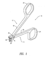
- Figure 1 shows a trimmer 10 having a pair of opposed articulating arms 12, 14 pivotally connected in scissor fashion at the point of their crossing intersection by a pivot pin 16.
- Each arm 12, 14 has a lever portion 18, 20, respectively, with finger/thumb grips 22, 24 at a proximal end thereof.
- Arm 12 has a holding jaw 26 at the distal end thereof, beyond the pivot pin 16.
- the holding jaw 26 holds a coiled strand such as a stent, for cutting by a cutter 28 extending from cutting jaw 30 disposed at the distal end of arm 14.
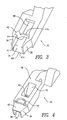
- Figure 2 shows that the cutter 28 has an arcuate (semi-circular) cross-sectional shape and is removably retained within the cutting jaw 30 by retention screw 32.
- cutter 28 could be removably held in cutting jaw 30 by a taper, dovetail, snap, or could be permanently affixed, e.g., by gluing, welding, embedding or by monolithic formation which would be especially appropriate for a disposable trimmer 10.
- Holding jaw 26 has a guiding channel 34 formed by two side walls 36, 38 and a bottom wall 40 with an upper surface 41.
- the upper surface 41 is radiused at the distal edge 41a thereof and at the proximal edge 41 b.
- the side walls 36, 38 preferably have a taper such that they are thinner at the distal end thereof to aid in the insertion of the side walls 36, 38 between adjacent coil loops as described below in reference to Figure 6 .
- Figure 3 shows that the holding jaw 26 has a cutter slot 42 having a cross-sectional shape that approximates that of the cutter 28.
- the cutter slot 42 is preferably provided with a sharp edge 44 which acts in opposition to the cutting edge 29 (see Figure 2 ) of cutter 28 to shear the coil to be cut.
- a coil passageway 46 extends through the holding jaw 26.
- a coil to be cut may be threaded through coil passageway 46 as shall be described below.
- Figure 4 shows the bottom surface 48 of the holder jaw 26.
- the cutter slot 42 extends through the bottom surface 48, as does the coil passageway 46, which flares outwardly along surface 50.
- the guiding channel 34 shown is approximately a trough shape, it may have different cross-sectional shapes and sizes depending on the profile of the fiber or wire to be cut.
- the length of guiding channel 34 should be less than the inner diameter of the coiled fiber in order to prevent distortion of coils during loading onto the holding jaw 26 and cutting.
- Angled surface 50 has an angle relative to surface 48 ranging from 30° to 60° for guiding the coiled strand (see 58 in Figure 6 ) through passageway 46.
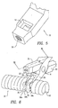
- FIG 5 shows cutting jaw 30 with cutter 28 and cutter retention screw 32 removed.
- a square aperture 52 receives base 54 (See Figure 7 ) from which cutter 28 projects.
- a threaded hole 56 receives cutter retention screw 32 ( Figure 7 ) and communicates with aperture 52 such that the retention screw 32 can press against base 54, holding it in the cutting jaw 30.
- Aperture 52 and base 54 can have other mating shapes that allow keyed orientation and prevent rotation.
- Cutter 28 can therefore be replaced when it becomes dull or otherwise damaged.
- Cutter 28 may also be replaced with a cutter 28 of different cross-sectional profile.
- the cutter slot 42 and the edge 44 in holding jaw 26 may also be removable to match the cross-sectional profile of the cutter 28.
- cutter 28 has a semi-circular cross-section, which produces a strand with a rounded cut end 64 ( Figure 8 ) as described below.
- a rounded cut end 64 is less prone to cut or pierce tissue into which it comes into contact.
- the trimmer 10 may be used to cut a coiled fiber or wire to a desired length leaving a rounded cut end 64 by the following method. Namely, by placing an end 60 of a coiled strand 58, such as a stent, between the side walls 36, 38 with the axis of the coiled strand 58 perpendicular to the guiding channel 34.
- the coiled strand 58 is then rotated about its axis until the end 60 exits the coil passageway 46. Rotation is continued, threading the coiled strand 58 through the holding jaw 26 until the strand 58 is properly positioned beneath the cutter 28, i.e., to provide the selected cut length.
- the cut is performed by applying compressive force to the arms 12, 14, causing the cutter 28 to be driven through the strand 58 and into the cutter slot 42.
- Figure 6 shows a coiled strand 58 loaded in holding jaw 26 of trimming device 10. End 60 of stent 58 is threaded onto holding jaw 26 as described above, such that side walls 36, 38 are between adjacent individual coil turns 58a, 58b, 58c of the coiled strand 58. Arms 12, 14 are then squeezed together, closing cutting jaw 30 on holding jaw 26 and cutting coiled strand 58.
- Figure 7 shows the trimmer 10 in the closed position with the cutter 28 fully through coiled strand 58.
- the cut portion 62 of coiled strand 58 is discharged from coil passage 46 of holding jaw 26.
- Figure 8 shows coiled strand 58 with a rounded cut end 64, as would be produced by cutting the coiled strand 58 with a trimmer 10.
- Trimmer 10 may be made of metals, such as carbon steel, stainless steel or titanium. If trimmer 10 is reusable, cutter 28 must have sufficient strength and hardness so as to make multiple cuts through the materials that comprise the coiled fiber or wire. If a disposable embodiment of trimmer 10 were desired, polymers may be incorporated for economical production.
Landscapes
- Health & Medical Sciences (AREA)
- Engineering & Computer Science (AREA)
- Mechanical Engineering (AREA)
- Orthopedic Medicine & Surgery (AREA)
- Surgery (AREA)
- Life Sciences & Earth Sciences (AREA)
- General Health & Medical Sciences (AREA)
- Heart & Thoracic Surgery (AREA)
- Medical Informatics (AREA)
- Molecular Biology (AREA)
- Animal Behavior & Ethology (AREA)
- Biomedical Technology (AREA)
- Public Health (AREA)
- Veterinary Medicine (AREA)
- Nuclear Medicine, Radiotherapy & Molecular Imaging (AREA)
- Vascular Medicine (AREA)
- Media Introduction/Drainage Providing Device (AREA)
- Scissors And Nippers (AREA)
- Wire Processing (AREA)
Abstract
Description
- The present invention relates to a trimmer for cutting a coiled strand, such as a polymer fiber or a strand of wire. More particularly, the present invention relates to a trimmer for cutting a coiled strand to a desired length prior to implantation in the body of a living creature, e.g., when the coiled strand is used as an arterial or urinary stent.
- Conventional pincer or scissor-action wire cutters are suitable for cutting straight or gently curved wires but are not optimal for cutting coiled wires. When trimming a coiled strand with multiple individual coil turns having no gaps or gaps between adjacent individual coil turns that are smaller than the thickness of the cutter's jaws, the adjacent coil turns must be spread apart in order for the jaws to close and make the cut. If the coil turns are spread beyond their elastic limit, they will be deformed, thus damaging the coil structure.
- A scissor, pincher or guillotine cut each result in a cut end which has sharp edges. It is preferable for the terminal ends of a wire or fiber which is coiled for use as a prosthetic implant to be rounded to avoid inadvertently cutting or piercing bodily tissues when placing the implant and during its use. For example, if a coiled stent has a sharp end, it could readily pierce the wall of an artery or other internal luminal structure into which it is inserted. Because the optimal dimensions of surgical prostheses are sometimes not known prior to the initial stages of surgical intervention (e.g., during visualization via radiography) either a large selection of prostheses must be kept on hand or the prosthesis must be dimensioned at the time of use. Coiled prostheses, such as stents may be trimmed to provide an optimal length. As noted, conventional cutters leave a sharp cut end and may distort a coil such as a stent. Subsequent rounding of a sharp cut end, e.g., by abrasion, represents added expense, personnel, time, complexity and apparatus to the surgical procedure and may damage the coiled structure.
- It would therefore be advantageous to have a coil trimmer that minimizes the deformation of the coil from cutting and produces a cut end with a reduced tendency to cut or pierce the bodily tissues that are exposed to the cut end.
- A rail scissor having a passageway for a rail is disclosed in
GB1000219 - a pair of articulating arms pivotally connected at a pivot joint, each of said pair of articulating arms having a lever portion disposed proximal to said pivot joint and a jaw portion disposed distal to said pivot joint, said jaw portions being urged together when said lever portions are urged together, a first of said jaw portions being a holding jaw for holding the coiled strand and a second of said jaw portions being a cutting jaw for cutting the strand, said holding jaw having a passageway therein through which the strand may be threaded to hold the coiled strand for cutting the strand at a selected location by said cutting jaw.
- The limitations of prior art cutting devices are addressed by the present invention, as defined in claim 1, which includes a cutting device for trimming a coiled strand and having a pair of articulating arms pivotally connected at a pivot joint. Each of the pair of articulating arms have a lever portion disposed proximal to the pivot joint and a jaw portion disposed distal to the pivot joint. The jaw portions are urged together when the lever portions are urged together. A first of the jaw portions is a holding jaw for holding the coiled strand. A second of the jaw portions is a cutting jaw for cutting the coiled strand. The holding jaw has a passageway therein through which the coiled strand may be threaded to aid in holding the coiled strand for cutting by the cutting jaw at a selected location.
- In accordance with a method of the present invention, as defined in
claim 16, a cutting device is provided having the characteristics described in the preceding paragraph. An end of the coiled strand is introduced through the passageway in the holding jaw. The coiled strand is rotated to advance the coiled strand through the passageway until the coiled strand is positioned beneath the cutting jaw at the selected location. The lever portions and the jaw portions are urged together cutting the coiled strand at the selected location. -
-
Figure 1 is a perspective view of a trimmer constructed in accordance with an exemplary embodiment of the present invention; -
Figure 2 is an enlarged view of holding and cutting jaws of the trimmer shown inFigure 1 ; -
Figure 3 is an enlarged view of a holding jaw of the trimmer ofFigure 2 viewed from the perspective indicated by the arrow emanating from the letter "B" inFigure 2 . -
Figure 4 is an enlarged view of the holding jaw ofFigures 2 and3 viewed from the perspective indicated by the arrow emanating from the letter "C" inFigure 2 . -
Figure 5 is an enlarged view of a cutting jaw of the trimming device ofFigure 2 viewed from the perspective indicated by the arrow emanating from the letter "C" inFigure 2 and with the cutter and cutter retention screw removed therefrom; -
Figure 6 is an enlarged view of the trimmer ofFigure 2 , showing a coiled fiber loaded into the device; -
Figure 7 is a cross-sectional view of the trimmer ofFigure 6 in a closed position having cut the fiber; taken along the cross-section line VII-VII and looking in the direction of the arrows; and -
Figure 8 is a side view of a coiled fiber with a rounded end produced by trimming the coiled fiber with a trimmer in accordance with the present invention; -
Figure 1 shows atrimmer 10 having a pair of opposedarticulating arms pivot pin 16. Eacharm lever portion thumb grips Arm 12 has aholding jaw 26 at the distal end thereof, beyond thepivot pin 16. As shall be explained more fully below, theholding jaw 26 holds a coiled strand such as a stent, for cutting by acutter 28 extending fromcutting jaw 30 disposed at the distal end ofarm 14. -
Figure 2 shows that thecutter 28 has an arcuate (semi-circular) cross-sectional shape and is removably retained within thecutting jaw 30 byretention screw 32. Alternatively,cutter 28 could be removably held in cuttingjaw 30 by a taper, dovetail, snap, or could be permanently affixed, e.g., by gluing, welding, embedding or by monolithic formation which would be especially appropriate for adisposable trimmer 10. - Holding jaw 26 has a guiding
channel 34 formed by twoside walls bottom wall 40 with anupper surface 41. Theupper surface 41 is radiused at thedistal edge 41a thereof and at theproximal edge 41 b. Theside walls side walls Figure 6 . -
Figure 3 shows that theholding jaw 26 has acutter slot 42 having a cross-sectional shape that approximates that of thecutter 28. Thecutter slot 42 is preferably provided with asharp edge 44 which acts in opposition to the cutting edge 29 (seeFigure 2 ) ofcutter 28 to shear the coil to be cut. Acoil passageway 46 extends through theholding jaw 26. A coil to be cut may be threaded throughcoil passageway 46 as shall be described below. -
Figure 4 shows thebottom surface 48 of theholder jaw 26. In the embodiment shown, thecutter slot 42 extends through thebottom surface 48, as does thecoil passageway 46, which flares outwardly alongsurface 50. While the guidingchannel 34 shown is approximately a trough shape, it may have different cross-sectional shapes and sizes depending on the profile of the fiber or wire to be cut. The length of guidingchannel 34 should be less than the inner diameter of the coiled fiber in order to prevent distortion of coils during loading onto theholding jaw 26 and cutting.Angled surface 50 has an angle relative tosurface 48 ranging from 30° to 60° for guiding the coiled strand (see 58 inFigure 6 ) throughpassageway 46. -
Figure 5 showscutting jaw 30 withcutter 28 andcutter retention screw 32 removed. Asquare aperture 52 receives base 54 (SeeFigure 7 ) from which cutter 28 projects. A threadedhole 56 receives cutter retention screw 32 (Figure 7 ) and communicates withaperture 52 such that theretention screw 32 can press againstbase 54, holding it in thecutting jaw 30.Aperture 52 andbase 54 can have other mating shapes that allow keyed orientation and prevent rotation.Cutter 28 can therefore be replaced when it becomes dull or otherwise damaged.Cutter 28 may also be replaced with acutter 28 of different cross-sectional profile. Thecutter slot 42 and theedge 44 in holdingjaw 26 may also be removable to match the cross-sectional profile of thecutter 28. - In the embodiment shown in
Figures 1 ,2 and6 ,cutter 28 has a semi-circular cross-section, which produces a strand with a rounded cut end 64 (Figure 8 ) as described below. Arounded cut end 64 is less prone to cut or pierce tissue into which it comes into contact. Referring toFigures 6 and7 , thetrimmer 10 may be used to cut a coiled fiber or wire to a desired length leaving arounded cut end 64 by the following method. Namely, by placing anend 60 of a coiledstrand 58, such as a stent, between theside walls strand 58 perpendicular to the guidingchannel 34. The coiledstrand 58 is then rotated about its axis until theend 60 exits thecoil passageway 46. Rotation is continued, threading the coiledstrand 58 through the holdingjaw 26 until thestrand 58 is properly positioned beneath thecutter 28, i.e., to provide the selected cut length. The cut is performed by applying compressive force to thearms cutter 28 to be driven through thestrand 58 and into thecutter slot 42. -
Figure 6 shows a coiledstrand 58 loaded in holdingjaw 26 of trimmingdevice 10.End 60 ofstent 58 is threaded onto holdingjaw 26 as described above, such thatside walls strand 58.Arms jaw 30 on holdingjaw 26 and cutting coiledstrand 58. -
Figure 7 shows thetrimmer 10 in the closed position with thecutter 28 fully through coiledstrand 58. Thecut portion 62 of coiledstrand 58 is discharged fromcoil passage 46 of holdingjaw 26.Figure 8 shows coiledstrand 58 with arounded cut end 64, as would be produced by cutting the coiledstrand 58 with atrimmer 10. -
Trimmer 10 may be made of metals, such as carbon steel, stainless steel or titanium. Iftrimmer 10 is reusable,cutter 28 must have sufficient strength and hardness so as to make multiple cuts through the materials that comprise the coiled fiber or wire. If a disposable embodiment oftrimmer 10 were desired, polymers may be incorporated for economical production.
Claims (19)
- A cutting device (10) for trimming a coiled strand (58), comprising:a pair of articulating arms (12, 14) pivotally connected at a pivot joint, each of said pair of articulating arms (12, 14) having a lever portion (18, 20) disposed proximal to said pivot joint and a jaw portion disposed distal to said pivot joint, said jaw portions being urged together when said lever portions (18, 20) are urged together, a first of said jaw portions being a holding jaw (26) for holding the coiled strand (58) and a second of said jaw portions being a cutting jaw (30) for cutting the coiled strand (58), said holding jaw (26) having an upper surface (41) proximate to said cutting jaw (30), a bottom surface (48) distal to said cutting jaw (30), and a passageway (46) extending through said upper surface (41) and said bottom surface through which the coiled strand (58) may be threaded to hold the coiled strand (58) for cutting the coiled strand (58) at a selected location by said cutting jaw (30);said holding jaw (26) having a guide channel (34) defined by a bottom wall (40) extending from a distal end of said holding jaw (26) to said passageway (46) and a first side wall (36) extending substantially perpendicularly from said bottom wall (40), said first side wall (36) positionable between two adjacent turns of the coiled strand (58) when said coiled strand (58) is threaded through said passageway (46).
- The cutting device (10) of Claim 1, further including a cutter (28) extending from said cutting jaw (30) toward said holding jaw (26), said cutter (28) having a cutting edge.
- The cutting device (10) of Claim 2, wherein said cutter (28) has a selected cross-sectional shape to impart a corresponding cross-sectional shape to a cut end of the coiled strand (58).
- The cutting device (10) of Claim 3, wherein said cutter (28) has an arcuate cross-sectional shape.
- The cutting device (10) of Claim 4, wherein said holding jaw (26) has an opposing edge opposing said cutting edge, said cutting edge and said opposing edge being brought into close proximity when said jaw portions are urged together.
- The cutting device (10) of Claim 5, wherein said passageway (46) is defined in part by a surface oriented approximately tangentially relative to the coiled strand (58) held in said holding jaw (26).
- The cutting device (10) of Claim 4, wherein said cutting edge is approximately semi-circular.
- The cutting device (10) of Claim 4, wherein said cutter (28) is removably retained in said cutting jaw (30).
- The cutting device (10) of Claim 8, wherein said cutter (28) has a base portion distal to said cutting edge and said cutting jaw (30) has a recess therein for receiving and retaining said base portion.
- The cutting device (10) of Claim 9, wherein said base portion is held in said recess by a retention screw (32) that presses against said base portion.
- The cutting device (10) of Claim 1, further comprising a second side wall (38) extending from said bottom wall (40) generally parallel to and spaced from said first side wall (36), the coiled strand (58) passing between said first and second side walls (36, 38) when said coiled strand (58) is threaded through said passageway (46).
- The cutting device (10) of Claim 11, wherein said first and second side walls (36, 38) taper down in thickness in the direction extending from said pivot joint to a distal end of said holding jaw (26).
- The cutting device (10) of Claim 12, wherein said bottom wall (40) is radiused at a distal end thereof to more closely approximate an interior curvature of the coiled strand (58).
- The cutting device (10) of Claim 13, where said bottom wall (40) is radiused proximate to said passageway (46) to more closely approximate an interior curvature of the coiled strand (58).
- The cutting device (10) of Claim 14, wherein the coiled strand (58) is held by said holding jaw (26) in an orientation with an axial length of said coil disposed approximately perpendicularly to said articulating arms (12, 14).
- A method for cutting a coiled strand (58) to a selected length, comprising the steps of:(A) providing a cutting device (10) having a pair of articulating arms (12, 14) pivotally connected at a pivot joint, each of said pair of articulating arms (12, 14) having a lever portion (18, 20) disposed proximal to said pivot joint and a jaw portion disposed distal to said pivot joint, said jaw portions being urged together when said lever portions (18, 20) are urged together, a first of said jaw portions being a holding jaw (26) for holding the coiled strand (58) and a second of said jaw portions being a cutting jaw (30) for cutting the coiled strand (58), said holding jaw (26) having an upper surface (41) proximate to said cutting jaw (30), a bottom surface (48) distal to said cutting jaw (30), and a passageway (46) extending through said upper surface (41) and said bottom surface (48) through which the coiled strand (58) may be threaded to hold the coiled strand (58) for cutting the coiled strand (58) at a selected location by said cutting jaw (30);
said holding jaw (26) having a guide channel (34) defined by a bottom wall (40) extending from a distal end of said holding jaw (26) to said passageway (46) and a first side wall (36) extending substantially perpendicularly from said bottom wall (40), said first side wall (36) positionable between two adjacent turns of the coiled strand (58) when said coiled strand (58) is threaded through said passageway (46);(B) introducing an end of the coiled strand (58) through the passageway (46) in the holding jaw (26);(C) rotating the coiled strand (58) to advance the coiled strand (58) through the passageway (46) until the coiled strand (58) is positioned beneath the cutting jaw (30) at the selected location;(D) urging said lever portions (18, 20) and said jaw portions together; and(E) cutting the coiled strand (58) at the selected location. - The method of Claim 16, wherein said guide channel (34) on the holding jaw (26) terminates at one end in the passageway (46) in the holding jaw (26) and wherein said step (B) of introducing includes passing the end of the coiled strand (58) through the guide channel (34) prior to introducing the coiled strand (58) through the passageway (46) in the holding jaw (26).
- The method of Claim 17, wherein said step of cutting results in the cut end being rounded.
- The method of Claim 16, wherein step of cutting is conducted without distorting the coiled strand (58).
Applications Claiming Priority (2)
| Application Number | Priority Date | Filing Date | Title |
|---|---|---|---|
| US302535 | 2002-11-22 | ||
| US10/302,535 US7257897B2 (en) | 2002-11-22 | 2002-11-22 | Trimmer for cutting a coiled strand |
Publications (2)
| Publication Number | Publication Date |
|---|---|
| EP1421908A1 EP1421908A1 (en) | 2004-05-26 |
| EP1421908B1 true EP1421908B1 (en) | 2008-05-28 |
Family
ID=32229919
Family Applications (1)
| Application Number | Title | Priority Date | Filing Date |
|---|---|---|---|
| EP03257363A Expired - Lifetime EP1421908B1 (en) | 2002-11-22 | 2003-11-21 | Trimmer for cutting a coiled strand |
Country Status (5)
| Country | Link |
|---|---|
| US (2) | US7257897B2 (en) |
| EP (1) | EP1421908B1 (en) |
| JP (1) | JP4467960B2 (en) |
| AT (1) | ATE396651T1 (en) |
| DE (1) | DE60321297D1 (en) |
Families Citing this family (10)
| Publication number | Priority date | Publication date | Assignee | Title |
|---|---|---|---|---|
| US8382810B2 (en) * | 2007-12-05 | 2013-02-26 | Arthrex, Inc. | Torsion cutter and cannulated cutter for cutting orthopedic fasteners |
| KR200463506Y1 (en) | 2008-04-10 | 2012-11-07 | 대우조선해양 주식회사 | Tool for removing coating of cable |
| USD590678S1 (en) * | 2008-09-03 | 2009-04-21 | Kam Por Paul Tong | Safety tile divider |
| WO2011085226A1 (en) * | 2010-01-08 | 2011-07-14 | Neurosurj Research & Development, LLC | Method and apparatus for cutting embolic coils |
| US20120115104A1 (en) * | 2010-08-17 | 2012-05-10 | Empire Technology Development Llc | Multi-rooted tooth extraction device |
| CN102302376B (en) * | 2011-06-09 | 2012-10-10 | 威海威高富森医用材料有限公司 | Suture line fixed length dividing and cutting machine |
| DE102011107178A1 (en) * | 2011-07-13 | 2013-01-17 | Karl Storz Gmbh & Co. Kg | Medical cutting instrument for cutting muscles and tendons |
| USD711712S1 (en) | 2012-02-24 | 2014-08-26 | Cercore Llc | Pair of handles for an instrument or tool |
| US20170340373A1 (en) * | 2015-04-30 | 2017-11-30 | Zhengzhou Zezheng Technical Services Ltd. | Kirschner wire bending device |
| KR102142644B1 (en) * | 2018-11-07 | 2020-08-07 | 한림대학교 산학협력단 | Device for removal of medical wires |
Family Cites Families (19)
| Publication number | Priority date | Publication date | Assignee | Title |
|---|---|---|---|---|
| US251604A (en) * | 1881-12-27 | Hog-nose trimmer | ||
| US2292729A (en) * | 1941-01-02 | 1942-08-11 | Sterling C Woodward | Cutting device |
| US2691416A (en) * | 1947-11-28 | 1954-10-12 | Gardner Wire Co | Coil spring cutter |
| NL104515C (en) | 1957-08-15 | |||
| FR1368172A (en) | 1963-05-31 | 1964-07-31 | Vitry Freres | Nail scissors |
| US3581400A (en) | 1969-10-29 | 1971-06-01 | Ormco Corp | Distal end cutter |
| US3972109A (en) * | 1975-08-08 | 1976-08-03 | Hans Sickinger Co. | Cutting fixture for spiral binders and method of manufacture |
| NL188438C (en) * | 1976-06-09 | 1992-06-16 | Pressmaster Tool Ab | DEVICE FOR REMOVING THE COATING OF AN ESPECIALLY ROD-SHAPED OBJECT. |
| DE2902460A1 (en) | 1978-01-26 | 1979-08-02 | Laschal Instrument | THREAD CUTTER |
| JPH02140503U (en) * | 1989-04-28 | 1990-11-26 | ||
| US5101563A (en) * | 1990-12-05 | 1992-04-07 | Orgelys Henri D | Nail clipper |
| US5463919A (en) * | 1991-11-02 | 1995-11-07 | Zortech International Limited | Apparatus for cutting wound coils |
| AU6329396A (en) | 1995-06-07 | 1996-12-30 | Staley, Robert N. | Orthodontic wire cutter |
| DE19607949C1 (en) * | 1996-03-01 | 1997-04-17 | Franz Krampe | Electrical conductors insulation stripping tool |
| US6061912A (en) | 1997-10-30 | 2000-05-16 | Gazaway; Eileen L. | Instrument for cutting multi-strand plastic fiber materials |
| US5966815A (en) | 1997-12-12 | 1999-10-19 | Ormco Corporation | Wire cutter with flush cut and holding ability |
| US6123001A (en) | 1998-02-11 | 2000-09-26 | Owen Oil Tools, Inc. | Detonating cord cutter |
| US6049985A (en) * | 1998-08-05 | 2000-04-18 | Schlumberger Technology Corporation | Detonating cord cutter |
| GB2350080A (en) | 1999-04-10 | 2000-11-22 | Liou Yaw Jang | Suture removal instrument |
-
2002
- 2002-11-22 US US10/302,535 patent/US7257897B2/en not_active Expired - Lifetime
-
2003
- 2003-11-21 AT AT03257363T patent/ATE396651T1/en not_active IP Right Cessation
- 2003-11-21 EP EP03257363A patent/EP1421908B1/en not_active Expired - Lifetime
- 2003-11-21 DE DE60321297T patent/DE60321297D1/en not_active Expired - Lifetime
- 2003-11-21 JP JP2003392642A patent/JP4467960B2/en not_active Expired - Fee Related
-
2007
- 2007-06-29 US US11/771,427 patent/US20080015622A1/en not_active Abandoned
Also Published As
| Publication number | Publication date |
|---|---|
| ATE396651T1 (en) | 2008-06-15 |
| US20080015622A1 (en) | 2008-01-17 |
| JP2004174245A (en) | 2004-06-24 |
| EP1421908A1 (en) | 2004-05-26 |
| JP4467960B2 (en) | 2010-05-26 |
| US7257897B2 (en) | 2007-08-21 |
| DE60321297D1 (en) | 2008-07-10 |
| US20040102800A1 (en) | 2004-05-27 |
Similar Documents
| Publication | Publication Date | Title |
|---|---|---|
| US20080015622A1 (en) | Trimmer for cutting a coiled strand | |
| US4817602A (en) | Vasectomy instrument | |
| US5033477A (en) | Method and apparatus for providing intrapericardial access and inserting intrapericardial electrodes | |
| US5779718A (en) | Method of anastomosing a vessel using a surgical clip applier | |
| US5133725A (en) | Adjustable intra-liminal valvulotome | |
| US6746457B2 (en) | Snared suture trimmer | |
| US5071428A (en) | Method and apparatus for providing intrapericardial access and inserting intrapericardial electrodes | |
| US4161951A (en) | Needle driver | |
| US4524771A (en) | Multiple curved surgical needle | |
| AU694445B2 (en) | Surgical clip applier | |
| JP4533886B2 (en) | Bone and cartilage implant delivery device | |
| US4788978A (en) | Surgical instrument for applying linear staple sutures and intersecting the tissue therebetween | |
| US4784139A (en) | Needle guide instrument | |
| EP0594004A1 (en) | Surgical clip applier | |
| JP2004517668A (en) | Surgical suturing instrument and method of use | |
| US20050010243A1 (en) | Device for cutting and holding a cornea during a transplant procedure | |
| EP0732901A1 (en) | Tissue cutting die | |
| JPH06205781A (en) | I-beam needle with real i-beam section | |
| US4098157A (en) | Method for suture removal | |
| EP3579784B1 (en) | Surgical tool for tissue sizing and transection | |
| EP0627199A2 (en) | Surgical needle-suture attachment for controlled suture release | |
| US20060178677A1 (en) | Hair punch | |
| EP0511323B1 (en) | Adjustable intra-luminal valvulotome | |
| JP2026511168A (en) | Epineurial junction implants, instruments, and methods | |
| GB2350080A (en) | Suture removal instrument |
Legal Events
| Date | Code | Title | Description |
|---|---|---|---|
| PUAI | Public reference made under article 153(3) epc to a published international application that has entered the european phase |
Free format text: ORIGINAL CODE: 0009012 |
|
| AK | Designated contracting states |
Kind code of ref document: A1 Designated state(s): AT BE BG CH CY CZ DE DK EE ES FI FR GB GR HU IE IT LI LU MC NL PT RO SE SI SK TR |
|
| AX | Request for extension of the european patent |
Extension state: AL LT LV MK |
|
| 17P | Request for examination filed |
Effective date: 20041105 |
|
| AKX | Designation fees paid |
Designated state(s): AT BE BG CH CY CZ DE DK EE ES FI FR GB GR HU IE IT LI LU MC NL PT RO SE SI SK TR |
|
| 17Q | First examination report despatched |
Effective date: 20070207 |
|
| GRAP | Despatch of communication of intention to grant a patent |
Free format text: ORIGINAL CODE: EPIDOSNIGR1 |
|
| GRAS | Grant fee paid |
Free format text: ORIGINAL CODE: EPIDOSNIGR3 |
|
| GRAA | (expected) grant |
Free format text: ORIGINAL CODE: 0009210 |
|
| AK | Designated contracting states |
Kind code of ref document: B1 Designated state(s): AT BE BG CH CY CZ DE DK EE ES FI FR GB GR HU IE IT LI LU MC NL PT RO SE SI SK TR |
|
| REG | Reference to a national code |
Ref country code: GB Ref legal event code: FG4D |
|
| REG | Reference to a national code |
Ref country code: CH Ref legal event code: NV Representative=s name: E. BLUM & CO. AG PATENT- UND MARKENANWAELTE VSP Ref country code: CH Ref legal event code: EP |
|
| REF | Corresponds to: |
Ref document number: 60321297 Country of ref document: DE Date of ref document: 20080710 Kind code of ref document: P |
|
| REG | Reference to a national code |
Ref country code: IE Ref legal event code: FG4D |
|
| PG25 | Lapsed in a contracting state [announced via postgrant information from national office to epo] |
Ref country code: SI Free format text: LAPSE BECAUSE OF FAILURE TO SUBMIT A TRANSLATION OF THE DESCRIPTION OR TO PAY THE FEE WITHIN THE PRESCRIBED TIME-LIMIT Effective date: 20080528 |
|
| PG25 | Lapsed in a contracting state [announced via postgrant information from national office to epo] |
Ref country code: FI Free format text: LAPSE BECAUSE OF FAILURE TO SUBMIT A TRANSLATION OF THE DESCRIPTION OR TO PAY THE FEE WITHIN THE PRESCRIBED TIME-LIMIT Effective date: 20080528 Ref country code: ES Free format text: LAPSE BECAUSE OF FAILURE TO SUBMIT A TRANSLATION OF THE DESCRIPTION OR TO PAY THE FEE WITHIN THE PRESCRIBED TIME-LIMIT Effective date: 20080908 |
|
| PG25 | Lapsed in a contracting state [announced via postgrant information from national office to epo] |
Ref country code: AT Free format text: LAPSE BECAUSE OF FAILURE TO SUBMIT A TRANSLATION OF THE DESCRIPTION OR TO PAY THE FEE WITHIN THE PRESCRIBED TIME-LIMIT Effective date: 20080528 Ref country code: NL Free format text: LAPSE BECAUSE OF FAILURE TO SUBMIT A TRANSLATION OF THE DESCRIPTION OR TO PAY THE FEE WITHIN THE PRESCRIBED TIME-LIMIT Effective date: 20080528 |
|
| NLV1 | Nl: lapsed or annulled due to failure to fulfill the requirements of art. 29p and 29m of the patents act | ||
| PG25 | Lapsed in a contracting state [announced via postgrant information from national office to epo] |
Ref country code: DK Free format text: LAPSE BECAUSE OF FAILURE TO SUBMIT A TRANSLATION OF THE DESCRIPTION OR TO PAY THE FEE WITHIN THE PRESCRIBED TIME-LIMIT Effective date: 20080528 Ref country code: SE Free format text: LAPSE BECAUSE OF FAILURE TO SUBMIT A TRANSLATION OF THE DESCRIPTION OR TO PAY THE FEE WITHIN THE PRESCRIBED TIME-LIMIT Effective date: 20080828 Ref country code: CZ Free format text: LAPSE BECAUSE OF FAILURE TO SUBMIT A TRANSLATION OF THE DESCRIPTION OR TO PAY THE FEE WITHIN THE PRESCRIBED TIME-LIMIT Effective date: 20080528 Ref country code: PT Free format text: LAPSE BECAUSE OF FAILURE TO SUBMIT A TRANSLATION OF THE DESCRIPTION OR TO PAY THE FEE WITHIN THE PRESCRIBED TIME-LIMIT Effective date: 20081028 |
|
| PG25 | Lapsed in a contracting state [announced via postgrant information from national office to epo] |
Ref country code: RO Free format text: LAPSE BECAUSE OF FAILURE TO SUBMIT A TRANSLATION OF THE DESCRIPTION OR TO PAY THE FEE WITHIN THE PRESCRIBED TIME-LIMIT Effective date: 20080528 Ref country code: BE Free format text: LAPSE BECAUSE OF FAILURE TO SUBMIT A TRANSLATION OF THE DESCRIPTION OR TO PAY THE FEE WITHIN THE PRESCRIBED TIME-LIMIT Effective date: 20080528 Ref country code: SK Free format text: LAPSE BECAUSE OF FAILURE TO SUBMIT A TRANSLATION OF THE DESCRIPTION OR TO PAY THE FEE WITHIN THE PRESCRIBED TIME-LIMIT Effective date: 20080528 |
|
| PLBE | No opposition filed within time limit |
Free format text: ORIGINAL CODE: 0009261 |
|
| STAA | Information on the status of an ep patent application or granted ep patent |
Free format text: STATUS: NO OPPOSITION FILED WITHIN TIME LIMIT |
|
| PG25 | Lapsed in a contracting state [announced via postgrant information from national office to epo] |
Ref country code: BG Free format text: LAPSE BECAUSE OF FAILURE TO SUBMIT A TRANSLATION OF THE DESCRIPTION OR TO PAY THE FEE WITHIN THE PRESCRIBED TIME-LIMIT Effective date: 20080828 Ref country code: EE Free format text: LAPSE BECAUSE OF FAILURE TO SUBMIT A TRANSLATION OF THE DESCRIPTION OR TO PAY THE FEE WITHIN THE PRESCRIBED TIME-LIMIT Effective date: 20080528 |
|
| 26N | No opposition filed |
Effective date: 20090303 |
|
| PG25 | Lapsed in a contracting state [announced via postgrant information from national office to epo] |
Ref country code: MC Free format text: LAPSE BECAUSE OF NON-PAYMENT OF DUE FEES Effective date: 20081130 |
|
| REG | Reference to a national code |
Ref country code: IE Ref legal event code: MM4A |
|
| PG25 | Lapsed in a contracting state [announced via postgrant information from national office to epo] |
Ref country code: IE Free format text: LAPSE BECAUSE OF NON-PAYMENT OF DUE FEES Effective date: 20081121 |
|
| PG25 | Lapsed in a contracting state [announced via postgrant information from national office to epo] |
Ref country code: CY Free format text: LAPSE BECAUSE OF FAILURE TO SUBMIT A TRANSLATION OF THE DESCRIPTION OR TO PAY THE FEE WITHIN THE PRESCRIBED TIME-LIMIT Effective date: 20080528 Ref country code: HU Free format text: LAPSE BECAUSE OF FAILURE TO SUBMIT A TRANSLATION OF THE DESCRIPTION OR TO PAY THE FEE WITHIN THE PRESCRIBED TIME-LIMIT Effective date: 20081129 Ref country code: LU Free format text: LAPSE BECAUSE OF NON-PAYMENT OF DUE FEES Effective date: 20081121 |
|
| PG25 | Lapsed in a contracting state [announced via postgrant information from national office to epo] |
Ref country code: TR Free format text: LAPSE BECAUSE OF FAILURE TO SUBMIT A TRANSLATION OF THE DESCRIPTION OR TO PAY THE FEE WITHIN THE PRESCRIBED TIME-LIMIT Effective date: 20080528 |
|
| PG25 | Lapsed in a contracting state [announced via postgrant information from national office to epo] |
Ref country code: GR Free format text: LAPSE BECAUSE OF FAILURE TO SUBMIT A TRANSLATION OF THE DESCRIPTION OR TO PAY THE FEE WITHIN THE PRESCRIBED TIME-LIMIT Effective date: 20080829 |
|
| PGFP | Annual fee paid to national office [announced via postgrant information from national office to epo] |
Ref country code: DE Payment date: 20131113 Year of fee payment: 11 Ref country code: CH Payment date: 20131112 Year of fee payment: 11 Ref country code: GB Payment date: 20131120 Year of fee payment: 11 Ref country code: FR Payment date: 20131108 Year of fee payment: 11 |
|
| PGFP | Annual fee paid to national office [announced via postgrant information from national office to epo] |
Ref country code: IT Payment date: 20131111 Year of fee payment: 11 |
|
| REG | Reference to a national code |
Ref country code: DE Ref legal event code: R119 Ref document number: 60321297 Country of ref document: DE |
|
| REG | Reference to a national code |
Ref country code: CH Ref legal event code: PL |
|
| GBPC | Gb: european patent ceased through non-payment of renewal fee |
Effective date: 20141121 |
|
| PG25 | Lapsed in a contracting state [announced via postgrant information from national office to epo] |
Ref country code: CH Free format text: LAPSE BECAUSE OF NON-PAYMENT OF DUE FEES Effective date: 20141130 Ref country code: LI Free format text: LAPSE BECAUSE OF NON-PAYMENT OF DUE FEES Effective date: 20141130 |
|
| REG | Reference to a national code |
Ref country code: FR Ref legal event code: ST Effective date: 20150731 |
|
| PG25 | Lapsed in a contracting state [announced via postgrant information from national office to epo] |
Ref country code: GB Free format text: LAPSE BECAUSE OF NON-PAYMENT OF DUE FEES Effective date: 20141121 Ref country code: DE Free format text: LAPSE BECAUSE OF NON-PAYMENT OF DUE FEES Effective date: 20150602 |
|
| PG25 | Lapsed in a contracting state [announced via postgrant information from national office to epo] |
Ref country code: FR Free format text: LAPSE BECAUSE OF NON-PAYMENT OF DUE FEES Effective date: 20141201 |
|
| PG25 | Lapsed in a contracting state [announced via postgrant information from national office to epo] |
Ref country code: IT Free format text: LAPSE BECAUSE OF NON-PAYMENT OF DUE FEES Effective date: 20141121 |