EP1420405A2 - Head retracting method/apparatus, and head actuator control circuit - Google Patents
Head retracting method/apparatus, and head actuator control circuit Download PDFInfo
- Publication number
- EP1420405A2 EP1420405A2 EP03256996A EP03256996A EP1420405A2 EP 1420405 A2 EP1420405 A2 EP 1420405A2 EP 03256996 A EP03256996 A EP 03256996A EP 03256996 A EP03256996 A EP 03256996A EP 1420405 A2 EP1420405 A2 EP 1420405A2
- Authority
- EP
- European Patent Office
- Prior art keywords
- head
- velocity
- predetermined
- actuator
- power supply
- Prior art date
- Legal status (The legal status is an assumption and is not a legal conclusion. Google has not performed a legal analysis and makes no representation as to the accuracy of the status listed.)
- Granted
Links
Images




Classifications
-
- G—PHYSICS
- G11—INFORMATION STORAGE
- G11B—INFORMATION STORAGE BASED ON RELATIVE MOVEMENT BETWEEN RECORD CARRIER AND TRANSDUCER
- G11B21/00—Head arrangements not specific to the method of recording or reproducing
- G11B21/02—Driving or moving of heads
- G11B21/12—Raising and lowering; Back-spacing or forward-spacing along track; Returning to starting position otherwise than during transducing operation
-
- G—PHYSICS
- G11—INFORMATION STORAGE
- G11B—INFORMATION STORAGE BASED ON RELATIVE MOVEMENT BETWEEN RECORD CARRIER AND TRANSDUCER
- G11B19/00—Driving, starting, stopping record carriers not specifically of filamentary or web form, or of supports therefor; Control thereof; Control of operating function ; Driving both disc and head
- G11B19/02—Control of operating function, e.g. switching from recording to reproducing
- G11B19/04—Arrangements for preventing, inhibiting, or warning against double recording on the same blank or against other recording or reproducing malfunctions
- G11B19/047—Recovery from power failure
-
- G—PHYSICS
- G11—INFORMATION STORAGE
- G11B—INFORMATION STORAGE BASED ON RELATIVE MOVEMENT BETWEEN RECORD CARRIER AND TRANSDUCER
- G11B21/00—Head arrangements not specific to the method of recording or reproducing
- G11B21/16—Supporting the heads; Supporting the sockets for plug-in heads
- G11B21/22—Supporting the heads; Supporting the sockets for plug-in heads while the head is out of operative position
-
- G—PHYSICS
- G11—INFORMATION STORAGE
- G11B—INFORMATION STORAGE BASED ON RELATIVE MOVEMENT BETWEEN RECORD CARRIER AND TRANSDUCER
- G11B5/00—Recording by magnetisation or demagnetisation of a record carrier; Reproducing by magnetic means; Record carriers therefor
- G11B5/48—Disposition or mounting of heads or head supports relative to record carriers ; arrangements of heads, e.g. for scanning the record carrier to increase the relative speed
- G11B5/54—Disposition or mounting of heads or head supports relative to record carriers ; arrangements of heads, e.g. for scanning the record carrier to increase the relative speed with provision for moving the head into or out of its operative position or across tracks
Definitions
- the present invention relates to an apparatus, a head retracting method and a head actuator control circuit for retracting a head of an information storage apparatus such as a magnetic disk drive, to a retract position when a power supply failure occurs.
- a magnetic medium (magnetic disk) is rotated by a spindle motor during operation, where the head is floating on the magnetic medium. If a power supply failure occurs in this status, the head retracting operation is executed. When a power supply failure occurs, power from the power supply to the driver of the VCM for moving the head is stopped, so the energy for retracting the head to be used must be other than that of the power supply.
- An example of energy other than the power supply is using the rotation energy of the spindle motor as power to drive the VCM and to retract the head (SPM BEMF rectification), or storing retract power in a battery including a capacitor when power is ON, and driving the VCM and retracting the head using the retract power when the power supply failure occurs.
- the former method is a mainstream method that is often used at the moment.
- the latter method which uses not the rotation energy of the spindle motor but electrically converted energy, is used for a disk apparatus which uses a small medium where the energy to be stored in the spindle motor is not sufficient.
- a head loading/unloading method is used. But for the loading/unloading method, unlike the CSS system, an unloading operation to climb over the ramp is required just before completely retracting the head. To stably climb over the ramp, approaching the ramp with an initial velocity and force in a predetermined range is necessary.
- a power supply failure occurs when following up a track in the outer zone of the disk, when following up a track in the inner zone of the disk, or when seeking toward the outer/inner zone, the position of the head and the velocity thereof at this point cannot be specified, but is in a wide range, which makes a stable head retracting (unload) operation difficult.
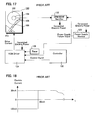
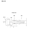
- the head retracting method shown in Fig. 17 to Fig. 19 has been proposed (e.g. Japanese Patent Application Laid-Open No. H5-54573 (especially, pages 3-4 and Fig. 2)).
- the magnetic disk drive 100 moves the arm 108 including the head using the VCM (Voice Coil Motor) 110 in the radial direction of the magnetic disk 102 which is rotated by the spindle motor 104, and reads/writes the data on a desired track.
- the ramp (spreader) 106 is disposed at the circumference position of the magnetic disk 102, and the head arm 108 is retracted onto the ramp 106.
- the power supply monitor 120 detects the power supply failure and notifies the power supply failure signal POWER SUPPLY FAILURE SIGNAL to the spindle counter electromotive force rectifier 122 and the VCM driver 124.
- the spindle counter electromotive force rectifier 122 generates power from the counter electromotive force of the spindle motor 104 which is inertia-rotating after the power supply failure occurred, and supplies the power to the VCM driver 124.
- the VCM driver 124 supplies a constant current with one polarity (-30 mA) to the VCM 110 for a predetermined time (80 ms) using the timer 126, as shown in Fig. 18, thereby moving the magnetic head (arm) 108 to the opposite direction (arrow a) from the spreader (ramp) 106 as shown in Fig. 19. Then as Fig. 18 shows, the VCM driver 124 supplies a constant current with opposite polarity (+30 mA) to the VCM 110 for a predetermined time, and then, as shown in Fig. 19, thereby moves the head 108 in a direction to the spreader (ramp) (arrow b) which is opposite of the first direction, to retract the head onto the spreader 106.
- the head is moved to a predetermined position after spending a predetermined time using the current drive function of the VCM driver as is, then the head is moved in the unload (retract) direction with a different predetermined current and predetermined time, so a stable unload operation can be expected if the variation of velocity and position of the head are within a predetermined range.
- the current is in proportion to the force and the force is in proportion to the acceleration, so depending on the moving velocity and the position of the head when a power supply failure occurs, it is difficult to guarantee the collision velocity of the head to the inner stop of the arm 108 when the head is driven to the direction opposite from the spreader (ramp) 106, and the head assembly may be damaged.
- the velocity of approaching the spreader (ramp) 106 also varies depending on the moving velocity and the position of the head when a power supply failure occurs, and it is possible that the arm 108 may contact the spreader 106 at high velocity and cause damage to the head assembly. Also it is difficult to design to safely retract (unload) the head with certainty at a velocity which does not cause damage to the head assembly, since dispersion depending on the disk drive is large due to the dispersion of external force.
- the head retracting method of the present invention is a head retracting method for retracting a head which at least reads information on a medium such as a disk to a retract position according to the power supply failure, including a first step of controlling the head to move to a predetermined position in an opposite direction from the retract position such that the velocity of the head becomes constant in the vicinity of the predetermined position, and a second step of controlling the head to move to the retract position after the head has reached the predetermined position such that the velocity of the head becomes constant around the retract position.
- the apparatus of the present invention is an apparatus for retracting a head which at least reads information on a medium such as a disk to a retract position according to the power supply failure, including an actuator for moving the head, and a control unit which controls the head to move to a predetermined position in an opposite direction from the retract position such that the velocity of the head becomes constant at least around the predetermined position, and controls the head to move to the retract position after the head reached the predetermined position such that the velocity of the head becomes constant at least around the retract position.
- the head actuator control circuit of the present invention is a head actuator control circuit for retracting a head which at least reads information on a medium to a retract position according to the power supply failure, including a power monitoring circuit for detecting the power supply failure, and an actuator control circuit which moving-controls the head to move to a predetermined position in an opposite direction from the retract position such that the velocity of the head becomes constant in the vicinity of the predetermined position, and moving-controls the head to move to the retract position after the head reached the predetermined position such that the velocity of the head becomes constant at least around the retract position.
- the head reaches to the inner stopper at a predetermined position in an opposite direction from the ramp at a predetermined velocity when the power supply failure occurs, so the head can stop at the inner stopper at the predetermined position without receiving a shock regardless what position the head is in or regardless what velocity the head is moving.
- the head is unloaded from the predetermined position at a constant velocity, so the head contacts the ramp and climbs onto the ramp at a predetermined velocity, which prevents damage to the head which would occur when contact force becomes excessive and the head contacts the medium with the arm inclined, therefore unloading is completed with certainty. Because of this, a storage apparatus with high reliability can be implemented.
- the above mentioned first step includes a step of controlling, the movement of the head to the predetermined position in an opposite direction from the retract position by driving the actuator for moving the head using a predetermined first voltage
- the above mentioned second step includes a step of controlling the movement of the head to the retract position by driving the actuator using a predetermined second voltage which is different from the first voltage
- control unit controls the movement of the head to a predetermined position in an opposite direction from the retract position by driving the actuator for moving the head using a predetermined first voltage, then controls the movement of the head to the retracting position by driving the actuator using a predetermined second voltage which is different from the first voltage.
- the actuator control circuit includes a voltage mode driver, and a controller for controlling the voltage mode driver to drive the actuator for moving the head using a predetermined first voltage such that the head moves to a predetermined position in an opposite direction from the retracting position, and then to drive the actuator using a predetermined second voltage which is different from the first voltage such that the head moves to the retract position.
- velocity is controlled using the counter electromotive voltage of the actuator by constant voltage driving, so the present invention can be easily implemented.
- the first step includes a step of controlling the movement of the head to a predetermined position in an opposite direction from the retract position according to the predetermined target velocity using a velocity signal fed back from the velocity detection unit for detecting the moving velocity of the head
- the second step includes a step of controlling the movement of the head to the retract position according to a scheduled target velocity using the velocity signal fed back from the velocity detection unit.
- the apparatus of the present invention further has a velocity detection unit for detecting the moving velocity of the head, and the control unit controls the movement of the head to a predetermined position in an opposite direction from the retract position according to the predetermined target velocity using the velocity signal fed back from the velocity detection unit, and then controls the movement of the head to the retract position according to the scheduled target velocity using the velocity signal fed back from the velocity detection unit.
- the actuator control circuit further has a velocity detection unit for detecting the moving velocity of the head, and a controller which controls the movement of the head to a predetermined position in an opposite direction from the retract position according to the predetermined target velocity using a velocity signal fed back from the velocity detection unit, and then controls the movement of the head to the retract position according to the scheduled target velocity using the velocity signal fed back from the velocity detection unit.
- the head is unloaded after controlling the velocity to the target velocity using the detected velocity of the velocity detection unit, thereby it is possible to unload the head with an accurate predetermined velocity.
- the head retracting method of the present invention further includes a step of braking the actuator for moving the head for a predetermined time occurrence of a power supply failure. Also, in the apparatus of the present invention, it is preferable that the control unit brakes the actuator for moving the head for a predetermined time according to the power supply failure. Also it is preferable that the head actuator control circuit further includes a brake circuit for braking the actuator for moving the head for a predetermined time according to the power supply failure.
- braking is executed when unloading starts, so the head can be unloaded stably even if the velocity of the head is fast.
- braking is executed by shorting both ends of the coil of the actuator for moving the head for a predetermined time according to the power supply failure.
- the control includes a step of controlling the movement of the head to the predetermined position in an opposite direction from the retract position by driving an actuator for moving the head for a predetermined time, and a step or means for controlling the movement of the head to the retract position by driving the actuator for another predetermined time.
- the velocity can be controlled based on time control, and unload control of the head can be easier.
- the head retracting method, apparatus and head actuator control circuit of the present invention include a step or means for monitoring the velocity of the head after the movement control in the first step, and shifting to the second step when the velocity of the head is a predetermined velocity or less. In this way, after detecting that the head has reached the predetermined position, the shift to unloading can be smooth.
- the apparatus of the present invention may be in the form of a disk apparatus.
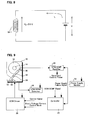
- Fig. 1 is a diagram depicting a magnetic disk drive as an example of an information storage apparatus of the invention
- Fig.2 is a diagram depicting the configuration of the VCM driver in Fig. 1
- Fig. 3 is a cross-sectional view depicting the arm and ramp in Fig. 1
- Fig. 4 is a top view depicting the arm and ramp in Fig. 3
- Fig. 5 is a diagram depicting the configuration of the controller in Fig. 1.
- the magnetic disk drive 10 comprises a magnetic disk 12, a spindle motor 14 for rotating the magnetic disk 12, an arm 16 which has a head slider at the tip, a VCM (Voice Coil Motor) 18 for moving the arm 16 including the head slider in the radial direction of the magnetic disk 12, and a ramp 20 which is disposed at an outer circumference position of the magnetic disk 12 and on which the arm 16 is retracted.
- VCM Vehicle Coil Motor
- the VCM 18 is comprised of a fixed magnet and a drive coil which is disposed at the rear end of the arm 16.
- the arm 16 is comprised of a swing arm which rotates with the rotation axis 24 as the center, and an inner stopper 22, for limiting the inner circumference position of the arm 16, is disposed on the VCM 18.
- the arm 16 and the ramp 20 will be described with reference to Fig. 3 and Fig. 4.
- the ramp 20 is comprised of a slant face 20-1 which ascends diagonally from the magnetic disk 12 side, a first flat face 20-2 which continues from the slant face 20-1, and a groove 20-3 which continues from the first flat face 20-2 to the second flat face 20-4.
- a lift 28 is created, and at the front part of the arm 16, a head slider 26 including the magnetic head is disposed.
- the lift 28 of the arm 16 climbs over the slant face 20-1 of the ramp 20 by the arm 16 moving to the right direction in Fig. 3 and Fig. 4, reaches the groove 20-3 via the first flat face 20-2, and stops at the step difference section with the second flat face. By this, the lift 28 is caught in the groove 20-3 and parks.
- the lift 28 climbs over the slant face of the groove 20 and the first flat face 20-2 by moving the arm 16 that parked at the groove 20-3, to the left direction in Fig. 3 and Fig. 4, and the arm 16 including the head returns onto the magnetic disk 12 by the lift 28 sliding down along the slant face 20-1.
- the power supply monitor circuit 32 monitors the power supply, and when it detects a power supply failure, the power supply monitor circuit 32 notifies the power supply failure signal POWER SUPPLY FAILURE SIGNAL to the spindle counter electromotive force rectifier 30 and the controller 40.
- the spindle counter electromotive force rectifier 30 generates power from the counter electromotive force of the spindle motor 14 which inertia-rotates after a power supply failure occurs, and supplies the power to the power supply monitor circuit 32, VCM counter electromotive force detector 34, controller 40 and VCM driver 36.
- the VCM counter electromotive force detector 34 detects the counter electromotive force in proportion to the velocity from the coil of the VCM 18, and outputs it to the controller 40.
- the controller 40 normally performs seek control and track following control. When the power supply failure signal POWER SUPPLY FAILURE SIGNAL is received, the controller 40 performs the later mentioned head unload processing.
- the VCM driver 36 drives the VCM 18 according to the instructions of the controller 40.
- the VCM driver 36 comprises a voltage mode driver 52 and a drive mode selector 50, in addition to the current mode driver 54, as shown in Fig. 2.
- the current mode driver 54 and the voltage mode driver 52 output current and voltage according to the control signal (Control Signal) of the controller 40.
- the drive mode selector 50 connects either the current mode driver 54 or the voltage mode driver 52 to the VCM 18 depending on the voltage/current control mode of the controller 40. In normal seek control and track following control, the VCM 18 is driven by current using the current mode driver 54.
- the controller 40 is comprised of an AD converter 60 which converts an analog VCM counter electromotive force signal into a digital value, an MPU (Micro Processor Unit) 62, a timer 64, a DA converter 68 which converts a digital control signal of the MPU 62 into an analog control signal, and a memory 66 which stores the programs and data of the MPU 62.
- AD converter 60 which converts an analog VCM counter electromotive force signal into a digital value
- MPU Micro Processor Unit
- timer 64 a timer 64
- a DA converter 68 which converts a digital control signal of the MPU 62 into an analog control signal
- a memory 66 which stores the programs and data of the MPU 62.
- Fig. 6 is a time chart of the VCM drive voltage and the in-plane moving velocity of the head according to the first embodiment of the present invention
- Fig. 7 is a flow chart depicting the unload processing when a power supply failure occurs
- Fig. 8 is a diagram depicting the unload operation in Fig. 7.
- time before the power supply failure is the time before "0", which is not included in the chart, and it is assumed that the power supply failure occurred at time "0" in Fig. 6.
- the power supply monitor circuit 32 When a power supply failure is detected, the power supply monitor circuit 32 notifies the power supply failure signal POWER SUPPLY FAILURE SIGNAL to the spindle counter electromotive force rectifier 30 and the controller 40. Receiving this notice, the spindle counter electromotive force rectifier 30 supplies the power generated using the spindle motor 14 as a generator to the power supply monitor circuit 32, VCM counter electromotive force detector 34, controller 40 and VCM driver 36.
- the MPU 62 of the controller 40 sets V1 [Volts] for the control signal and sets the voltage/current control mode Voltage/Current Control Mode to voltage mode, and sends both of these signals to the VCM driver 36.
- the VCM driver 36 starts driving the VCM 18 with the voltage of V1 volts in the voltage mode from time "0" in Fig. 6.
- the digital control value V1 of the MPU 62 is converted into an analog value by the DA converter 68, is input to the voltage mode driver 52 and the current mode driver 54 of the VCM driver 36, and the voltage mode signal of the MPU 62 is input to the drive mode selector 50 of the VCM driver 36.
- the drive mode selector 50 has three inputs, and is comprised of two output terminal selectors, so the voltage of V1 volts of the voltage mode driver 52 is applied to both ends of the coil of the VCM 18 connected to the two output terminals.
- the velocity of the head (arm) 16 changes as shown by the dotted lines depending on the head position and the velocity when the power supply failure occurs, and eventually converges to the velocity Ve11.
- the velocity of the arm 16 converges to the velocity Ve11 defined by the voltage V1, regardless of the velocity and position of the arm 16.
- the head (arm) 16 is driven to the inner side (opposite direction from the ramp) of the magnetic disk 12, and collides with the inner stopper 22 at velocity Veil.
- the MPU 62 of the controller 40 reads the counter electromotive voltage signal VCM BEMF from the VCM counter electromotive voltage detector 34 using the AD converter 60 based on the time 'a' counted by the timer 64, and converts it into the head velocity v based on the above mentioned relationship.
- the time 'a' is defined to be the time when the head (arm) 16 is expected to collide with the inner stopper 22 after the constant voltage driving with the voltage V1 is started, no matter where the head is positioned on the magnetic disk.
- the MPU 62 of the controller 40 compares the converted velocity v with a predetermined slice value Slice 1 (see Fig. 6). If the converted velocity v is not the slice value Slice 1 or less, the head (arm) 16 has not yet stopped by colliding with the inner stopper 22, so processing returns to step S14.
- step S18 If the converted velocity v is the slice value Slice 1 or less, on the other hand, the MPU 62 of the controller 40 judges whether the converted velocity v is at the slice value Slice 1 or less during a predetermined time T1. If the converted velocity v is not at the slice value Slice 1 or less during the predetermined time T1, processing returns to step S14.
- the MPU 62 of the controller 40 reads the counter electromotive voltage signal VCM BEMF from the VCM counter electromotive voltage detector 34 using the AD converter 60 based on the time 'd' counted by the timer 64, and converts it into the head velocity v based on the above mentioned relationship.
- This time 'd' is defined to be the time when the head is expected to climb over the ramp 20 from the inner stopper 22 after constant voltage driving with voltage V2 has started.
- the MPU 62 of the controller 40 compares the converted velocity v with a predetermined slice value Slice 2 (see Fig. 6). If the converted velocity v is not at the slice value Slice 2 or less, the lift 28 of the head (arm) 16 is not caught in the groove 20-3 of the ramp 20 and is not stopped, so processing returns to step S22.
- step S26 If the converted velocity v is at the slice value Slice 2 or less, on the other hand, the MPU 62 of the controller 40 judges whether the converted velocity v is at the slice value Slice 2 or less during a predetermined time T3. If the converted velocity v is not at the slice value Slice 2 or less during the predetermined time T3, processing returns to step S22.
- the head 16 is moved in an opposite direction from the ramp 20 by constant voltage driving.
- constant voltage driving the head is moved to a position opposite from the ramp 20 with a predetermined velocity with which BEMF of the VCM 18 and the drive voltage are perfectly balanced.
- the head reaches the predetermined position (inner stopper)
- the head contacts against the stopper and the head velocity becomes almost "0". So by detecting the state where the head velocity is close to "0", the arrival of the head at the predetermined position is detected, and the head is unloaded by constant voltage driving in the ramp 20 direction. And the head climbs over the ramp with a predetermined velocity with which the BEMF of the VCM and the drive voltage are perfectly balanced.
- the head 16 reaches to the inner stopper at a predetermined position in an opposite direction from the ramp 20 at a predetermined velocity when the power supply failure occurs, so the head can stop at the inner stopper at the predetermined position without shock, regardless what position the head is in or regardless what velocity the head is moving.
- the head is unloaded from the predetermined position at a constant velocity, so the head contacts the ramp and climbs onto the ramp at a predetermined velocity, which prevents damage to the head which would occur when contact force becomes excessive and the head contacts the magnetic disk with the arm inclined, therefore unloading is completed reliably. Because of this, a magnetic disk apparatus with high reliability can be implemented.
- retracting of the head may be detected by the BEMF of the VCM. And by this the unload operation can be confirmed.
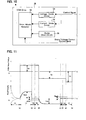
- Fig. 9 is a diagram depicting the configuration of the second embodiment of the magnetic disk drive of the present invention
- Fig. 10 is a diagram depicting the configuration of the VCM driver in Fig. 9.
- the magnetic disk drive 10 comprises a magnetic disk 12, a spindle motor 14 for rotating the magnetic disk 12, an arm 16 which has a head slider at the tip, a VCM (Voice Coil Motor) 18 for moving the arm 16 including the head slider in the radius direction of the magnetic disk 12, and a ramp 20 which is disposed at an outer circumference position of the magnetic disk 12 and on which the arm 16 is retracted.
- VCM Vehicle Coil Motor
- the VCM 18 is comprised of a fixed magnet and a drive coil which is disposed at the rear end of the arm 16.
- the arm 16 is comprised of a swing arm which rotates around the rotation axis 24 as the center, and the inner stopper 22 for limiting the inner circumference position of the arm 16 is disposed on the VCM 18.
- the configuration of the arm 16 and the ramp 20 are the same as those shown in Fig. 3 and Fig. 4.
- the power supply monitor circuit 32 monitors the power supply, and when a power supply failure is detected, the power supply monitor circuit 32 notifies the power supply failure signal POWER SUPPLY FAILURE SIGNAL to the spindle counter electromotive force rectifier 30 and the controller 40.
- the spindle counter electromotive force rectifier 30 generates power from the counter electromotive force of the spindle motor 14 which inertia-rotates after the power supply failure occurs, and supplies the power to the power supply monitor circuit 32, VCM counter electromotive force detector 34, controller 40 and VCM driver 36.
- the VCM counter electromotive force detector 34 detects the counter electromotive force in proportion to the velocity from the coil of the VCM 18, and outputs it to the controller 40.
- the controller 40 normally performs seek control and track following control. When the power supply failure signal POWER SUPPLY FAILURE SIGNAL is received, the controller 40 performs the later mentioned head unload processing.
- the VCM driver 36 drives the VCM 18 according to the instructions from the controller 40.
- the VCM driver 36 comprises a voltage mode driver 52, a brake (short) circuit 56 and a drive mode selector 50, in addition to the current mode driver 54, as shown in Fig. 10.
- the current mode driver 54 and the voltage mode driver 52 output current and voltage according to the control signal (Control Signal) of the controller 40.
- the brake circuit 56 shorts both ends of the VCM coil 18-1 and brakes the VCM 18.
- the drive mode selector 50 connects either the brake circuit 56, the current mode driver 54 or the voltage mode driver 52 to the VCM 18 depending on the brake/voltage/current control mode of the controller 40.
- the VCM 18 is driven by current using the current mode driver 54.
- the configuration of the controller 40 is the same as the one shown in Fig. 5.
- Fig. 11 is a time chart of the VCM drive voltage and the in-plane moving velocity of the head according to the second embodiment of the present invention
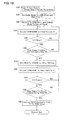
- Fig. 12 is a flow chart depicting unload processing when a power supply failure occurs.
- the power supply monitor circuit 32 When a power supply failure is detected, the power supply monitor circuit 32 notifies the power supply failure signal POWER SUPPLY FAILURE SIGNAL to the spindle counter electromotive force rectifier 30 and the controller 40. Receiving this notice, the spindle counter electromotive force rectifier 30 supplies the power generated using the spindle motor 14 as a generator to the power supply monitor circuit 32, VCM counter electromotive force detector 34, controller 40 and VCM driver 36.
- the MPU 62 of the controller 40 sets the brake/voltage/current control mode Brake/Voltage/Current Control Mode to the brake mode, and sends the brake mode signal to the drive mode selector 50 of the VCM driver 36.
- the VCM driver 36 shorts both ends of the coil 18-1 of the VCM 18 using the brake circuit 56.
- the short time is T1.
- the MPU 62 of the controller 40 sets V1 [Volts] for the control signal Control Signal, and sets the brake/voltage/current control mode Brake/Voltage/Current Control Mode to voltage mode, and sends both of these signals to the VCM driver 36.
- the VCM driver 36 starts driving the VCM 18 with the voltage of V1 volts in voltage mode from the time "0" in Fig. 6.
- the digital control value V1 of the MPU 62 is converted into an analog value by the DAC converter 68, is input to the voltage mode driver 52 and the current mode driver 54 of the VCM driver 36, and the voltage mode signal of the MPU 62 is input to the drive mode selector 50 of the VCM driver 36.
- the drive mode selector 50 has four inputs and is comprised of two output terminal selectors, so the voltage of V1 volts of the voltage mode driver 52 is applied to both ends of the coil of the VCM 18 connected to the two output terminals.
- the MPU 62 of the controller 40 reads the counter electromotive voltage signal VCM BEMF from the VCM counter electromotive voltage detector 34 using the AD converter 60 based on the time 'b' after the time T2, which is counted by the timer 64, and converts it into the head velocity v based on the above mentioned relationship.
- the time 'b' is defined to be the time when the head (arm) 16 is expected to collide with the inner stopper 22 after constant voltage driving with the voltage V1 is started, no matter where the head is positioned on the magnetic disk.
- the MPU 62 of the controller 40 compares the converted velocity v with a predetermined slice value Slice 1 (see Fig. 11). If the converted velocity v is not the slice value Slice 1 or less, the head (arm) 16 has not yet stopped by colliding with the inner stopper 22, so processing returns to step S36.
- step S40 If the converted velocity v is the slice value Slice 1 or less, on the other hand, the MPU 62 of the controller 40 judges whether the converted velocity v is at the slice value Slice 1 or less during a predetermined time T3. If the converted velocity v is not at the slice value Slice 1 or less during the predetermined time T3, processing returns to step S36.
- the MPU 62 of the controller 40 reads the counter electromotive voltage signal VCM BEMF from the VCM counter electromotive voltage detector 34 using the AD converter 60 based on the time 'e' counted by the timer 64, and converts it into the head velocity v based on the above mentioned relationship.
- This time 'e' is defined to be the time when the head is expected to climb over the ramp 20 from the inner stopper 22 after constant voltage driving with voltage V2 has started.
- the MPU 62 of the controller 40 compares the converted velocity v with a predetermined slice value Slice 2 (see Fig. 11). If the converted velocity v is not at the slice value Slice 2 or less, the lift 28 of the head (arm) 16 is not caught in the groove 20-3 of the ramp 20 and is not stopped, so processing returns to step S44.
- step S48 If the converted velocity v is at the slice value Slice 2 or less, on the other hand, the MPU 62 of the controller 40 judges whether the converted velocity v is at the slice value Slice 2 or less during a predetermined time T5. If the converted velocity v is not at the slice value Slice 2 or less during the predetermined time T5, processing returns to step S44.
- braking is executed for the VCM and then the head 16 is moved in an opposite direction from the ramp 20. Since braking is executed, the head velocity is reduced to "0", even if the seek velocity during seeking is fast.
- the head is moved to a position opposite from the ramp 20 with a predetermined velocity with which the BEMF of the VCM 18 and the drive voltage are perfectly balanced.
- the head contacts against the stopper and the head velocity becomes almost "0". So by detecting the state where the head velocity is close to "0", the head reaching the predetermined position is detected, and the head is unloaded by constant voltage driving in the ramp 20 direction. The head climbs over the ramp with a predetermined velocity with which the BEMF of the VCM and the drive voltage are perfectly balanced.
- the head 16 reaches the inner stopper at a predetermined position in an opposite direction from the ramp 20 with a predetermined velocity after braking is executed for the VCM 18 when the power supply failure occurs, so the head can stop at the inner stopper at a predetermined position without shock, regardless what position the head is in or regardless what velocity the head is moving. Also because of braking, the head can reach the inner stopper at a predetermined velocity in a short time, even if the seek velocity during seeking is fast. The head is unloaded from the predetermined position at a constant velocity, so the head contacts the ramp and climbs onto the ramp at a predetermined velocity, which prevents damage to the head which would occur when contact force becomes excessive and the head contacts the magnetic disk with the arm inclined, therefore unloading is completed definitely. Because of this, a magnetic disk apparatus with high reliability can be implemented.
- Fig. 13 is a diagram depicting the configuration of the third embodiment of the magnetic disk apparatus of the present invention
- Fig. 14 is a diagram depicting the configuration of the VCM driver in Fig. 13
- Fig. 15 is a diagram depicting the configuration of the local controller in Fig. 13.
- the magnetic disk drive 10 comprises a magnetic disk 12, a spindle motor 14 for rotating the magnetic disk 12, an arm 16 which has a head slider at the tip, a VCM (Voice Coil Motor) 18 for moving the arm 16 including the head slider in the radius direction of the magnetic disk 12, and a ramp 20 which is disposed at an outer circumference position of the magnetic disk 12 and on which the arm 16 is retracted.
- VCM Vehicle Coil Motor
- the VCM 18 is comprised of a fixed magnet and a drive coil which is disposed at the rear end of the arm 16.
- the arm 16 is comprised of a swing arm which rotates around the rotation axis 24 as the center, and the inner stopper 22 for limiting the inner circumferential position of arm 16 is disposed on the VCM 18.
- the configuration of the arm 16 and the ramp 20 are the same as those shown in Fig. 3 and Fig. 4.
- the power supply monitor circuit 32 monitors the power supply, and when a power supply failure is detected, the power supply monitor circuit 32 notifies the power supply failure signal POWER SUPPLY FAILURE SIGNAL to the spindle counter electromotive force rectifier 30 and the VCM driver 36.
- the spindle counter electromotive force rectifier 30 generates power from the counter electromotive force of the spindle motor 14 which inertia-rotates after the power supply failure occurs, and supplies the power to the power supply monitor circuit 32, VCM counter electromotive force detector 34 and VCM driver 36.
- the VCM counter electromotive force detector 34 detects the counter electromotive force in proportion to the velocity from the coil of the VCM 18, and outputs it to the controller 40 and the VCM driver 36.
- the controller 40 outputs the control signal to the VCM driver 36, and executes seek control and track following control.
- the controller 40 also performs head unload processing in cases other than a power supply failure, using the counter electromotive voltage signal from the VCM counter electromotive voltage detector 34.
- the VCM driver 36 drives the VCM 18 according to the instructions of the controller 40.
- the VCM driver 36 comprises a voltage mode driver 52, a brake (short) circuit 56, a drive mode selector 50 and local controller 58, in addition to the current mode driver 54, as shown in Fig. 14.
- the current mode driver 54 and the voltage mode driver 52 output current and voltage according to the control signal (Control Signal) of the local controller 58.
- the brake circuit 56 shorts both ends of the VCM coil 18-1, and performs braking of the VCM 18.
- the drive mode selector 50 receives the power supply failure signal POWER SUPPLY FAILURE SIGNAL, and connects either the brake circuit 56 or the voltage mode driver 52 to the VCM 18.
- the current mode driver 54 drives the VCM 18 with current in normal seek control and track following control.
- the local controller 58 is comprised of the AD converter 70 for converting the analog VCM counter electromotive force signal into a digital value, MPU (Micro Processor Unit) 72, timer 74, DA converters 78 and 80 for converting the digital control signals of the MPU 72 into analog control signals, and a memory 76 for storing the programs and data of the MPU 72, as shown in Fig. 15.
- AD converter 70 for converting the analog VCM counter electromotive force signal into a digital value
- MPU Micro Processor Unit
- timer 74 timer 74
- DA converters 78 and 80 for converting the digital control signals of the MPU 72 into analog control signals
- a memory 76 for storing the programs and data of the MPU 72, as shown in Fig. 15.
- This embodiment is the embodiment in Fig. 9 and Fig. 10, wherein unload processing executed by the MPU 62 of the controller 40, when the power supply failure occurs, is executed by the local controller 58 disposed in the VCM driver 36. By this, the load of the controller 40 can be decreased.
- Fig. 16 is a time chart depicting the change of VCM drive voltage and head velocity in the third embodiment. This time chart is essentially the same as the one shown in Fig. 11.
- the local controller 58 detects the power supply failure with executing the unload processing shown in Fig. 12, braking is executed for the VCM and then the head 16 is moved in an opposite direction from the ramp 20. Since braking is executed, the head velocity is reduced to "0", even if the seek velocity during seeking is fast.
- the head is moved to a position opposite from the ramp 20 at a predetermined velocity with which the BEMF of the VCM 18 and the drive voltage are perfectly balanced. When the head reaches the predetermined position (inner stopper), the head contacts against the stopper and the head velocity becomes almost "0".
- the head reaching the predetermined position is detected, and the head is unloaded by constant voltage driving in the ramp 20 direction.
- the head climbs over the ramp at a predetermined velocity with which the BEMF of the VCM and the drive voltage are perfectly balanced.
- the head 16 reaches the inner stopper at a predetermined position in an opposite direction from the ramp 20 at a predetermined velocity after braking is executed for the VCM 18 when the power supply failure occurs, so the head can stop at the inner stopper at the predetermined position without shock, no matter what position the head is in or no matter what velocity the head is moving. Because it is braked, the head can reach the inner stopper at a predetermined velocity in a short time, even if the seek velocity during seeking is fast.
- the head is unloaded from the predetermined position at a constant velocity, so the head contacts the ramp and climbs onto the ramp at a predetermined velocity, which prevents damage to the head which would occur when contact force becomes excessive and the head contacts the magnetic disk with the arm inclined, therefore unloading is completed certainly. Because of this, a magnetic disk apparatus with high reliability can be implemented.
- the local controller 58 performs the unload processing in Fig. 12, but may perform unload processing of the embodiment in Fig. 7.
- the number of magnetic disks mounted on the magnetic disk apparatus may be one or a plurality of disks.
- the structure of the ramp and the structure of the lift of the arm may have a different structure.
- brake processing is added, but brake processing may be omitted except for the case where the head velocity is detected from the VCM counter electromotive voltage when the power supply failure is detected, and the head velocity is faster than a predetermined velocity. Instead of a fixed braking time, the velocity of the head may be detected and braking continued until the velocity of the head becomes a predetermined velocity or less.
- the head reaches to the inner stopper at a predetermined position in an opposite direction from the ramp at a predetermined velocity when the power supply failure occurs, so the head can stop at the inner stopper at the predetermined position without shock, regardless what position the head is in or regardless what velocity the head is moving.
- the head is unloaded from the predetermined position at a constant velocity, so the head contacts the ramp and climbs onto the ramp at a predetermined velocity, which prevents damage to the head which would occur when contact force becomes excessive and the head contacts the magnetic disk with the arm inclined, therefore unloading is reliably completed. Because of this, a magnetic disk apparatus with high reliability can be implemented.
Landscapes
- Supporting Of Heads In Record-Carrier Devices (AREA)
- Rotational Drive Of Disk (AREA)
- Moving Of Heads (AREA)
Abstract
Description
Claims (22)
- A head retracting method for retracting a head, which at least reads information stored on a recording medium, to a retract position following a power supply failure, comprising:a first step of controlling movement of said head to a predetermined position in an opposite direction from said retract position such that the velocity of said head becomes constant in the vicinity of said predetermined position; anda second step of controlling movement of said head to said retract position after said head reaches said predetermined position such that the velocity of said head becomes constant in the vicinity of said retract position.
- The head retracting method according to Claim 1, wherein said first step comprises a step of driving an actuator for moving said head with a predetermined first voltage so as to move the head to the predetermined position in an opposite direction from said retract position, and
said second step comprises a step of driving said actuator with a predetermined second voltage which is different from said first voltage so as to move the head to said retract position. - The head retracting method according to Claim 1, wherein said first step comprises a step of controlling the movement of the head to said predetermined position in an opposite direction from said retract position according to said predetermined target velocity using a velocity signal fed back from velocity detection unit for detecting the moving velocity of said head,
and said second step comprises a step of controlling the movement of the head to said retract position according to a scheduled target velocity using the velocity signal fed back from said velocity detection unit. - The head retracting method according to Claim 1, further comprising a step of braking an actuator for moving said head for a predetermined time, following said power supply failure.
- The head retracting method according to Claim 2, further comprising a step of braking the actuator by shorting both ends of the coil of the actuator for moving said head for a predetermined time, following said power supply failure.
- The head retracting method according to Claim 1, wherein said first step comprises a step of driving an actuator for moving said head for a predetermined time so as to move the head to the predetermined position in an opposite direction from said retract position,
and said second step comprises a step of driving said actuator for another predetermined time so as to move the head to said retract position. - The head retracting method of any preceding claim, further comprising a third step of monitoring the velocity of said head after said movement control of said first step and shifting to said second step when the velocity of said head is a predetermined velocity or less.
- An apparatus for retracting a head which at least reads information stored on a recording medium, to a retract position following a power supply failure, comprising:an actuator for moving said head; anda control unit which controls said head to move to a predetermined position in an opposite direction from said retract position such that the velocity of said head becomes constant in the vicinity of said predetermined position, and controls said head to said retract position after said head reaches said predetermined position such that the velocity of said head constant in the vicinity of said retract position.
- The disk apparatus according to Claim 8, wherein said control unit drives the actuator using a predetermined first voltage so as to move the head to said predetermined position in an opposite direction from said retract position, and then drives said actuator using a predetermined second voltage which is different from said first voltage so as to move the head to said retract position.
- The apparatus according to Claim 8, further comprising a velocity detection unit for detecting the moving velocity of said head,
and wherein said control unit controls the movement of the head to said predetermined position in an opposite direction from said retract position according to said predetermined target velocity using a velocity signal fed back from said velocity detection unit and then controls the movement of the head to said retract position according to a scheduled target velocity using the velocity signal fed back from said velocity detection unit. - The apparatus according to Claim 8, wherein said control unit brakes the actuator for moving said head for a predetermined time according to said power supply failure.
- The apparatus according to Claim 11, wherein said control unit brakes the actuator by shorting both ends of the coil of the actuator for moving said head for a predetermined time according to said power supply failure.
- The apparatus according to Claim 8, wherein said control unit controls the movement of the head to a predetermined position in an opposite direction from said storage position by driving the actuator for moving said head for a predetermined time, and then controls the movement of the head to said retract position by driving said actuator for another predetermined time.
- The apparatus according to Claim 8, wherein said control unit monitors the velocity of said head after said movement control to said predetermined position, and shifts to the movement control to said retract position when the velocity of said head is at a predetermined velocity or less.
- The apparatus according to Claim 8, wherein said predetermined position is a position of a stopper of said actuator, and further comprising a ramp for parking said head at said retract position.
- A head actuator control circuit for retracting a head which at least reads information on a recording medium, to a retract position following a power supply failure, comprising:a power monitoring circuit for detecting said power supply failure; andan actuator control circuit which controls movement of said head to a predetermined position in an opposite direction from said retract position such that a velocity of said head becomes constant in the vicinity of said predetermined position according to the power supply failure detection of said power supply monitoring circuit, and then controls movement of said head to said retract position after said head reaches said predetermined position such that the velocity of said head moving to said retract position becomes constant in the vicinity of said retract position.
- The head actuator control circuit according to Claim 16, wherein said actuator control circuit comprises:a voltage mode driver; anda controller for controlling said voltage mode driver to drive the actuator for moving said head using a predetermined first voltage so as to move the head to said predetermined position in an opposite direction of said retract position, and then to drive said actuator using a predetermined second voltage which is different from said first voltage so as to move the head to said retract position.
- The head actuator control circuit according to Claim 16,
wherein said actuator control circuit comprises:a velocity detection unit for detecting the moving velocity of said head; and a controller which controls the movement of the head to said predetermined position in an opposite direction of said retract position according to said predetermined target velocity using a velocity signal fed back from said velocity detection unit, and then controls the movement of the head to said retract position according to a scheduled target velocity using the velocity signal fed back from said velocity detection unit. - The head actuator control circuit according to Claim 16, further comprising a brake circuit for braking the actuator for moving said head for a predetermined time following said power supply failure.
- The head actuator control circuit according to Claim 19, wherein said brake circuit comprises a circuit for shorting both ends of the coil of the actuator for moving said head for a predetermined time following said power supply failure.
- The head actuator control circuit according to Claim 16, wherein said control unit controls the movement of the head to said predetermined position in an opposite direction from said retract position by driving the actuator for moving said head for a predetermined time, then controls the movement of the head to said retract position by driving said actuator for another predetermined time.
- The head actuator control circuit according to Claim 16, wherein said control unit monitors the velocity of said head after control of movement to said predetermined position is performed, and shifts to the control of movement to said retract position when the velocity of said head is at a predetermined velocity or less.
Applications Claiming Priority (2)
| Application Number | Priority Date | Filing Date | Title |
|---|---|---|---|
| JP2002328632 | 2002-11-12 | ||
| JP2002328632 | 2002-11-12 |
Publications (3)
| Publication Number | Publication Date |
|---|---|
| EP1420405A2 true EP1420405A2 (en) | 2004-05-19 |
| EP1420405A3 EP1420405A3 (en) | 2006-05-10 |
| EP1420405B1 EP1420405B1 (en) | 2008-10-15 |
Family
ID=32105533
Family Applications (1)
| Application Number | Title | Priority Date | Filing Date |
|---|---|---|---|
| EP03256996A Expired - Lifetime EP1420405B1 (en) | 2002-11-12 | 2003-11-05 | Head retracting method/apparatus, and head actuator control circuit |
Country Status (5)
| Country | Link |
|---|---|
| US (1) | US7072135B2 (en) |
| EP (1) | EP1420405B1 (en) |
| KR (1) | KR20040044115A (en) |
| CN (1) | CN1501389A (en) |
| DE (1) | DE60324082D1 (en) |
Families Citing this family (40)
| Publication number | Priority date | Publication date | Assignee | Title |
|---|---|---|---|---|
| US20040100718A1 (en) * | 2002-11-23 | 2004-05-27 | Texas Instruments Incorporated | Digital processor controlled method and circuit for retracting a head carriage assembly to a parked position in a mass data storage device, or the like, by actively detecting a collision with a crash stop |
| US7309967B2 (en) * | 2004-03-31 | 2007-12-18 | Hitachi Global Storage Technologies Netherlands B.V. | Motor drive circuitry with regenerative braking for disk drive |
| JP2006252601A (en) * | 2005-03-08 | 2006-09-21 | Hitachi Global Storage Technologies Netherlands Bv | Magnetic disk apparatus and control method thereof |
| SG126010A1 (en) * | 2005-03-31 | 2006-10-30 | Seagate Technology Llc | Ramp unload in disc drives |
| CN100407330C (en) * | 2005-09-22 | 2008-07-30 | 深圳易拓科技有限公司 | Skew block mounting clamping apparatus |
| KR100734293B1 (en) * | 2005-12-14 | 2007-07-02 | 삼성전자주식회사 | Voice coil motor driving method of hard disk drive, head unloading device and recording medium suitable for this |
| US7274529B2 (en) * | 2006-02-10 | 2007-09-25 | Hitachi Global Storage Technologies Netherlands B.V. | Disk drive with adaptive actuator braking upon unexpected power loss |
| JP4798037B2 (en) * | 2006-03-31 | 2011-10-19 | パナソニック株式会社 | Hard disk drive status monitoring device and hard disk drive status monitoring method |
| US7421359B2 (en) * | 2006-06-05 | 2008-09-02 | Seagate Technology Llc | Detecting back electromotive force voltage |
| JP2008186533A (en) * | 2007-01-30 | 2008-08-14 | Fujitsu Ltd | Emergency evacuation verification device and medium storage device |
| US7573670B1 (en) | 2007-09-27 | 2009-08-11 | Western Digital Technologies, Inc. | Disk drive seeking to OD track and then ramping velocity to implement fast unload |
| US20100053802A1 (en) * | 2008-08-27 | 2010-03-04 | Masaki Yamashita | Low Power Disk-Drive Motor Driver |
| US8988811B1 (en) | 2008-05-23 | 2015-03-24 | Western Digital Technologies, Inc. | Disk drive toggling VCM inductor compensation to reduce acoustic noise |
| US7876522B1 (en) | 2008-09-30 | 2011-01-25 | Western Digital Technologies, Inc. | Disk drive updating estimate of voice coil resistance to account for resistance change prior to unload operation |
| JP5549119B2 (en) * | 2009-05-31 | 2014-07-16 | 日本テキサス・インスツルメンツ株式会社 | Disk drive |
| US20100332922A1 (en) * | 2009-06-30 | 2010-12-30 | Mediatek Inc. | Method for managing device and solid state disk drive utilizing the same |
| US8072703B1 (en) * | 2010-06-23 | 2011-12-06 | Western Digital Technologies, Inc. | Disk drive detecting when head is parked on ramp |
| US8767354B1 (en) * | 2011-12-08 | 2014-07-01 | Western Digital Technologies, Inc. | Data storage device employing cascaded voltage regulators during power failure |
| US9093105B2 (en) * | 2011-12-09 | 2015-07-28 | Western Digital Technologies, Inc. | Disk drive charging capacitor using motor supply voltage during power failure |
| US8665551B1 (en) | 2011-12-22 | 2014-03-04 | Western Digital Technologies, Inc. | Disk drive adjusting gain and offset of BEMF velocity sensor during self writing of spiral tracks |
| US8724422B1 (en) | 2012-02-29 | 2014-05-13 | Western Digital Technologies, Inc. | System and method for charging back-up charge storage element for data storage device using spindle phase switching elements |
| TWI436582B (en) * | 2012-05-15 | 2014-05-01 | Anpec Electronics Corp | Motor driving circuit and method thereof |
| EP2880502A4 (en) * | 2012-07-31 | 2016-07-20 | Hewlett Packard Entpr Dev Lp | Receiving input power measurements to manage a rectifier |
| US9780700B2 (en) * | 2013-09-27 | 2017-10-03 | Seagate Technology Llc | Efficient energy recovery in disk drive during power loss |
| US9105290B2 (en) * | 2013-12-11 | 2015-08-11 | Seagate Technology Llc | Discontinuous charge/discharge power source for retract application |
| US9264263B2 (en) * | 2014-04-21 | 2016-02-16 | Qualcomm Incorporated | Serdes voltage-mode driver with skew correction |
| US9076473B1 (en) | 2014-08-12 | 2015-07-07 | Western Digital Technologies, Inc. | Data storage device detecting fly height instability of head during load operation based on microactuator response |
| US9230593B1 (en) | 2014-12-23 | 2016-01-05 | Western Digital Technologies, Inc. | Data storage device optimizing spindle motor power when transitioning into a power failure mode |
| CN105988716A (en) * | 2015-02-09 | 2016-10-05 | 深圳市硅格半导体有限公司 | Storage device and mode conversion method thereof |
| US9355676B1 (en) | 2015-03-25 | 2016-05-31 | Western Digital Technologies, Inc. | Data storage device controlling amplitude and phase of driving voltage to generate power from a spindle motor |
| JP2018055756A (en) | 2016-09-30 | 2018-04-05 | ルネサスエレクトロニクス株式会社 | Control device, magnetic disk control system, and control method for controlling disk storage device |
| JP6662830B2 (en) * | 2017-09-19 | 2020-03-11 | ファナック株式会社 | Prediction device, machine learning device, control device, and production system |
| US9940958B1 (en) * | 2017-11-07 | 2018-04-10 | Western Digital Technologies, Inc. | Data storage device employing delayed braking to unload multiple voice coil motors |
| US10152994B1 (en) * | 2017-11-09 | 2018-12-11 | Western Digital Technologies, Inc. | Data storage device concurrently disconnecting multiple voice coil motors from spindle motor BEMF voltage during unload |
| US9997182B1 (en) * | 2017-11-09 | 2018-06-12 | Western Digital Technologies, Inc. | Data storage device employing balanced current drive to unload multiple voice coil motors |
| US10014018B1 (en) * | 2017-12-15 | 2018-07-03 | Western Digital Technologies, Inc. | Data storage device seeking multiple voice coil motors using a limited current supply |
| JP2021015659A (en) * | 2019-07-10 | 2021-02-12 | 株式会社東芝 | Hard disk drive |
| JP7400404B2 (en) * | 2019-11-28 | 2023-12-19 | 株式会社レゾナック | Recording/playback device |
| CN111883184A (en) * | 2020-07-02 | 2020-11-03 | 唐敏敏 | Hard disk auxiliary protection magnetic head equipment for computer |
| US12080327B2 (en) * | 2022-08-01 | 2024-09-03 | Stmicroelectronics S.R.L. | Method of operating hard disk drives and corresponding control circuit |
Family Cites Families (4)
| Publication number | Priority date | Publication date | Assignee | Title |
|---|---|---|---|---|
| JP2659478B2 (en) | 1991-08-20 | 1997-09-30 | アルプス電気株式会社 | Magnetic disk drive |
| US6169382B1 (en) * | 1998-07-02 | 2001-01-02 | Seagate Technology Llc | Adapting seek velocity profile to destination track location |
| US6140784A (en) * | 1999-06-09 | 2000-10-31 | Quantum Corporation | Power off velocity control for disk drives |
| US6850382B2 (en) * | 2001-03-14 | 2005-02-01 | Seagate Technology Llc | Method for wear reduction of a disc surface through stimulated take off of a head for a disc drive |
-
2003
- 2003-10-29 US US10/694,742 patent/US7072135B2/en not_active Expired - Lifetime
- 2003-11-05 DE DE60324082T patent/DE60324082D1/en not_active Expired - Fee Related
- 2003-11-05 EP EP03256996A patent/EP1420405B1/en not_active Expired - Lifetime
- 2003-11-11 KR KR1020030079295A patent/KR20040044115A/en not_active Ceased
- 2003-11-12 CN CNA200310103843A patent/CN1501389A/en active Pending
Also Published As
| Publication number | Publication date |
|---|---|
| EP1420405B1 (en) | 2008-10-15 |
| KR20040044115A (en) | 2004-05-27 |
| EP1420405A3 (en) | 2006-05-10 |
| US7072135B2 (en) | 2006-07-04 |
| DE60324082D1 (en) | 2008-11-27 |
| US20040080858A1 (en) | 2004-04-29 |
| CN1501389A (en) | 2004-06-02 |
Similar Documents
| Publication | Publication Date | Title |
|---|---|---|
| EP1420405B1 (en) | Head retracting method/apparatus, and head actuator control circuit | |
| US6765746B2 (en) | Method and apparatus employed in disk drive for retracting head when power supply has been interrupted | |
| US6859340B2 (en) | Method and device for retracting an actuator | |
| US6236527B1 (en) | Disk drive with actuator load/unload controller | |
| US5889629A (en) | Method and apparatus for controlling disk drive head parking during power interruption | |
| US6798603B1 (en) | Disk drive unlatching an actuator arm at a first spindle speed during a first spin-up mode and a second spindle speed during a second spin-up mode | |
| CN101017680B (en) | Disk drive with adaptive actuator that brakes during unexpected power loss | |
| US7046475B2 (en) | Apparatus and method for controlling head unload operation in disk drive | |
| EP0769774A2 (en) | Retraction of a disc drive actuator | |
| US6282049B1 (en) | Applying a ramped voltage source across an actuator coil to retract a disc drive actuator | |
| US6560057B1 (en) | Head positioning system for a disk drive during a power down condition | |
| US6134071A (en) | Disk drive, load/unload unit, and control method thereof | |
| US12266385B2 (en) | Data storage device having dual actuators and method for emergency power off retract (EPOR) of dual actuators | |
| JP4286110B2 (en) | Disk device, head retracting method, and head actuator control circuit | |
| US11837264B2 (en) | Data storage device having dual actuators and method for data egress throttling during emergency power off retract (EPOR) | |
| US7483233B2 (en) | Method and apparatus for driving VCM unloading HDD head | |
| US20030184907A1 (en) | Method for boosting a disc drive motor stiction breakaway performance | |
| US7633702B1 (en) | Method and apparatus for powering voice coil motor retract circuit while braking spindle | |
| JP2000021073A (en) | Magnetic disk drive and head retract method applied to the magnetic disk drive when power is cut off | |
| EP1686568A2 (en) | Seek error retry method of a disk device and disk device | |
| JP2000057714A (en) | Disk storage device and head unloading device applied to the device | |
| US20010026415A1 (en) | Disk storage apparatus and head load control method | |
| US7430088B2 (en) | Retracting method of hard disk drive, hard disk drive adopting the method, and recording medium storing program for executing the method | |
| US20230282236A1 (en) | Magnetic disk device | |
| JP2000251429A (en) | Magnetic disk drive and head unload method at power-off |
Legal Events
| Date | Code | Title | Description |
|---|---|---|---|
| PUAI | Public reference made under article 153(3) epc to a published international application that has entered the european phase |
Free format text: ORIGINAL CODE: 0009012 |
|
| AK | Designated contracting states |
Kind code of ref document: A2 Designated state(s): AT BE BG CH CY CZ DE DK EE ES FI FR GB GR HU IE IT LI LU MC NL PT RO SE SI SK TR |
|
| AX | Request for extension of the european patent |
Extension state: AL LT LV MK |
|
| PUAL | Search report despatched |
Free format text: ORIGINAL CODE: 0009013 |
|
| AK | Designated contracting states |
Kind code of ref document: A3 Designated state(s): AT BE BG CH CY CZ DE DK EE ES FI FR GB GR HU IE IT LI LU MC NL PT RO SE SI SK TR |
|
| AX | Request for extension of the european patent |
Extension state: AL LT LV MK |
|
| 17P | Request for examination filed |
Effective date: 20060626 |
|
| AKX | Designation fees paid |
Designated state(s): DE FR GB |
|
| 17Q | First examination report despatched |
Effective date: 20070524 |
|
| GRAP | Despatch of communication of intention to grant a patent |
Free format text: ORIGINAL CODE: EPIDOSNIGR1 |
|
| GRAC | Information related to communication of intention to grant a patent modified |
Free format text: ORIGINAL CODE: EPIDOSCIGR1 |
|
| GRAS | Grant fee paid |
Free format text: ORIGINAL CODE: EPIDOSNIGR3 |
|
| GRAA | (expected) grant |
Free format text: ORIGINAL CODE: 0009210 |
|
| AK | Designated contracting states |
Kind code of ref document: B1 Designated state(s): DE FR GB |
|
| REG | Reference to a national code |
Ref country code: GB Ref legal event code: FG4D |
|
| REF | Corresponds to: |
Ref document number: 60324082 Country of ref document: DE Date of ref document: 20081127 Kind code of ref document: P |
|
| PGFP | Annual fee paid to national office [announced via postgrant information from national office to epo] |
Ref country code: DE Payment date: 20081203 Year of fee payment: 6 |
|
| PGFP | Annual fee paid to national office [announced via postgrant information from national office to epo] |
Ref country code: FR Payment date: 20081022 Year of fee payment: 6 |
|
| PGFP | Annual fee paid to national office [announced via postgrant information from national office to epo] |
Ref country code: GB Payment date: 20090129 Year of fee payment: 6 |
|
| PLBE | No opposition filed within time limit |
Free format text: ORIGINAL CODE: 0009261 |
|
| STAA | Information on the status of an ep patent application or granted ep patent |
Free format text: STATUS: NO OPPOSITION FILED WITHIN TIME LIMIT |
|
| 26N | No opposition filed |
Effective date: 20090716 |
|
| REG | Reference to a national code |
Ref country code: GB Ref legal event code: 732E Free format text: REGISTERED BETWEEN 20091112 AND 20091118 |
|
| REG | Reference to a national code |
Ref country code: FR Ref legal event code: TP |
|
| GBPC | Gb: european patent ceased through non-payment of renewal fee |
Effective date: 20091105 |
|
| REG | Reference to a national code |
Ref country code: FR Ref legal event code: ST Effective date: 20100730 |
|
| PG25 | Lapsed in a contracting state [announced via postgrant information from national office to epo] |
Ref country code: FR Free format text: LAPSE BECAUSE OF NON-PAYMENT OF DUE FEES Effective date: 20091130 |
|
| PG25 | Lapsed in a contracting state [announced via postgrant information from national office to epo] |
Ref country code: DE Free format text: LAPSE BECAUSE OF NON-PAYMENT OF DUE FEES Effective date: 20100601 |
|
| PG25 | Lapsed in a contracting state [announced via postgrant information from national office to epo] |
Ref country code: GB Free format text: LAPSE BECAUSE OF NON-PAYMENT OF DUE FEES Effective date: 20091105 |