BACKGROUND OF THE INVENTION
1. Field of the Invention
The invention relates an information
recording apparatus which records information on a
recording medium having a user data area and a spare
area, and also relates to an information recording
method, a program for recording information, a
memory medium having the information recording
program stored thereon, and an information recording
system.
2. Description of the Related Art
The Mt. Rainier standard has been
proposed as a format which adds a defect management
function to the rewritable CD disk or the DVD disk.
The Mt. Rainier standard offers a format which
provides compatibility with the original record
format of the CD-RW disk and the DVD+RW disk that
are rerecordable while newly adding a defective
management function.
In the following, a description will be
given of the features of the Mt. Rainier standard.
(1) First Feature
The Mt. Rainier standard is characterized
in that a defect management area and a spare area
are positioned within the user data area of the
conventional format.
Specifically, the defect management area
resides both in a main table area (hereinafter
referred to as an MTA) within the lead-in zone and
in a secondary table area (hereinafter referred to
as an STA) provided in the user data area of the
conventional format.
Reallocated data are recorded on the spare
area (hereinafter referred to as an SA) provided in
the user data area of the conventional format.
With this provision, spare sectors are
properly read by use of a particular driver
(hereinafter called an MRW driver) even when a disk
recorded by the Mt. Rainier format is inserted into
a drive that does not support the Mr. Rainier
standard (such a drive will hereinafter be referred
to as conventional drive). This is because the
defect management area and the spare area exist in
the user data area, which is accessible by the
conventional drive.
For example, a DVD+MRW disk, which is a
DVD+RW disk recorded by the Mt. Rainier format, may
be inserted into a conventional drive. Since the
DVD+MRW disk is compatible with the conventional
DVD+RW standard, the conventional drive detects the
insertion of the DVD+RW disk, and reports this to a
user. In response to the report that a DVD+RW
disk has been inserted, a MRW driver reads a
predetermined address in the disk to find that a
DVD+MRW disk is actually inserted. This is
because the Mt. Rainier standard prescribes that
information indicative of the Mt. Rainier disk be
recorded at the predetermined address in the user
data area. Upon finding that the DVD+MRW disk is
inserted, the MRW driver reads the defect management
area recorded at a predetermined position within the
user data area, thereby obtaining information about
spare sectors.
The spare area also resides in the user
data area. In response to a data-read request from
the user, the MRW driver identifies a relevant spare
area based on the defect management information if
the data-read request includes a request for access
to a defect area, and requests the conventional
drive to read the relevant spare area. In this
manner, the conventional drive can properly read the
DVD+MRW disk that contains spare sectors. If the
drive supports the DVD+MRW format (such a drive will
hereinafter be referred to as an MRW drive), it can
properly read spare sectors without the use of such
MRW driver as described above.
The difference between DVD+MRW and CD-MRW,
which is the Mt. Rainier standard for CD-RW, is in
the arrangement of SAs. Both CD-MRW and DVD+MRW
have their spare areas in the user data area. While
CD-MRW has its spare areas dispersed in the user
data area, DVD+MRW has its spare areas concentrated
in the innermost circumference and the outermost
circumference of the user data area. An SA in the
innermost circumference of the user data area is
referred to as an SA1, and an SA in the outermost
circumference is referred to as an SA2.
(2) Second Feature
Another feature of the Mt. Rainier
standard is background formatting. In the
background formatting, a user making a formatting
request is notified of a formatting completion
message after recording only a portion of the lead-in
zone. The remaining portions are recorded with
dummy data when there is no access from the user.
After receiving the formatting completion message,
the user can record or reproduce data on a random-access
basis with respect to all the user data area
on the disk.
Moreover, it is possible to take a disk
out during the background formatting before the
recording of all the disk area is completed. When a
disk is ejected during the background formatting, it
is necessary for the conventional drive to properly
read the disk having only a partial formatting. To
this end, dummy data is recorded on unrecorded areas
intervening between recorded data. Further, the
outermost address (i.e., the last written address
LWA) recorded with user data or recorded by
formatting is used as a start position from which a
temporary STA (hereinafter referred to as a TSTA) is
recorded, for the purpose of allowing the MRW driver
to obtain defect management information. At the end,
a temporary lead-out (hereinafter referred to as a
TLO) is recorded, followed by the ejection of the
disk.
A DVD+MRW disk, for which reallocation to
the SA2 is made after a defect is found during the
formatting operation, may be taken out. In such a
case, a temporary SA2 (hereinafter referred to as a
TSA2) is set aside from the LWA, and spared data is
then copied to the SA2, followed by recording the
TSTA and the TLO. This is done for the purpose of
shortening a time required for the ejection of the
disk. That is, since the SA2 in DVD+MRW is located
at the outermost circumference of the user data area,
the process of inserting dummy data into the
unrecorded areas up to the SA2 is omitted for the
purpose of time saving. The TSA2 is a temporary
spare area for use by the conventional drive to read
the reallocated data. The size of the TSA2 is a sum
of all the areas used for the spare purpose in the
SA2.
(3) Example
Figs. 7A and 7B are illustrative drawings
showing the recording format of CD-MRW and DVD+MRW.
Fig. 7A illustrates the recording format of CD-MRW,
and Fig. 7B is the recording format of DVD+MRW.
Both CD-MRW and DVD+MRW are divided into a
lead-in zone, a data zone, and a lead-out zone.
An MTA (main table area) is provided in
the lead-in zone.
A GAA (general application area), an SA
(spare area), a DA (data area), and an STA
(secondary table area) are provided in the data zone.
In the Mt. Rainier format, defect management
information and information about the formatting
status are recorded on the MTA and STA. The STA is
a copy of what is stored in the MTA, and is situated
in the data zone. User data is recorded on the DA.
If a defect is found in the DA during the recording
of data, reallocation to the SA is carried out.
Further, the GAA stores information for use by an
MRW driver to identify a MRW disk when a MRW disk is
inserted into a conventional drive.
In this manner, MRW arranges an STA as a
defect management area and an SA as a spare area in
the data zone which is accessible by a conventional
drive, thereby providing for the conventional drive
to read the spare area.
The difference between CD-MRW and DVD+MRW
resides in the arrangement of SA areas. CD-MRW
disperses the SAs and the DAs sparsely as shown in
Fig. 7A, whereas DVD+MRW arranges the SA1 at the
innermost circumference of the data zone and the SA2
at the outermost circumference as shown in Fig. 7B.
As a result, the DAs which record user data are
contiguous.
Figs. 8A and 8B are illustrative drawings
showing the way CD-MRW and DVD+MRW are partially
formatted. Fig. 8A illustrates the recording format
of CD-MRW, and Fig. 8B is the recording format of
DVD+MRW.
In CD-MRW, a TSTA (temporary secondary
table area) is recorded following a user-recorded
area or an area recorded by formatting with dummy
data, and a TLO (temporary lead-out) is added. MTA
information is copied to the TSTA, storing defect
management information and information about
formatting status. An MRW driver refers to the TSTA
to acquire spare information. Since SAs are
sparsely dispersed in CD-MRW, a defect that is
detected in an i-th DA area during the background
formatting is generally replaced by an i-th SA area.
In the case of DVD+MRW, on the other hand,
spare areas exist only in the SA1 and the SA2. The
SA2 may thus be used during the background
formatting. If the SA2 is used, it is necessary to
insert dummy data all the way from the position
where formatting is done to the position of the SA2
so as to allow a conventional drive to read the data
reallocated to the SA2. Since the SA2 is situated
at the very end of the user data area, however, a
disk cannot be taken out until formatting is
complete if the SA2 is used as a replacement. In
order to avoid this in DVD+MRW, as shown in Fig. 8B,
data spared by (i.e., reallocated to) the SA2 is
copied to the TSA2 (temporary SA2) following the
formatted area. The disk is then ejected after
recording the TSTA and the TLO following the TSA2.
In Figs. 8A and 8B, "De-iced" represents
areas where data is recorded. That is, "iced"
indicates unrecorded areas, and "De-iced" means
eliminating unrecorded areas.
(4) Art Disclosed in Publication
Japanese Patent Application Publication No.
10-021552 discloses an information recording
apparatus that records spared data on the user data
area. This information recording apparatus sets
aside a portion of the user data area as a spare
area if a large number of defect areas may exist
depending on the conditions of the disk. The set-aside
portion of the user data area will then be
used as a spare area.
When the Mt. Rainier standard is employed,
adding data to a partially formatted DVD+MRW gives
rise to the following problems. Figs. 9A through
9D are illustrative drawings for explaining problems
that occur in DVD+MRW.
Figs. 9A through 9D illustrate a case in
which the updating of a TSA2 becomes necessary in
DVD+MRW. Fig. 9A shows a partially formatted
DVD+MRW. In Fig. 9A, data spared by (i.e.,
reallocated to) the SA2 is copied to a TSA2
following the formatted area, followed by the
recorded TSTA and TLO.
(1) First Problem
Since the TSA2 resides in the user data
area, as illustrated in Fig. 9B, there may be a case
in which the TSA2 is overwritten by user data.
Here, a drive is configured to resume
background formatting if the TSTA and the TLO, which
exist in the user data area, are similarly
overwritten by user data. Once the formatting
resumes, a TSA2, a TSTA, and a TLO will again be
recorded from the new LWA at the time of disk
discharge. This prevents these areas from being
destroyed by the overwriting user data.
However, no consideration is given to the
fact that a TSA2 may be overwritten by user data.
When a TSA2 is overwritten by user data, therefore,
the TSA2 will not be rerecorded by the resumed
background formatting or the like. Because of this,
if a TSA2 is overwritten by user data as illustrated
in Fig. 9B, the TSA2 will be left overwritten. When
a disk having a TSA2 overwritten by user data is
inserted into a conventional drive, the drive gives
incorrect spare data to the user. Namely, when a
TSA2 is overwritten by user data during the process
of adding user data to a partially formatted disk,
the TSA2 will no longer correctly represent the
information of the SA2. If such a disk is inserted
in a conventional drive, incorrect information will
be given to a user.
(2) Second Problem
There may be a case in which a user wishes
to store data in an area replaced by the SA2. In
this case, as shown Fig. 9C, the data in the SA2 is
updated.
While the TSA2 is provided for a
conventional drive to read reallocated data, an MRW
drive accesses the SA2 to record data on the SA2.
As a result, the SA2 and the TSA2 end up storing
different data.
In this manner, the SA2 may be updated
during the process of adding user data to a
partially formatted disk, resulting in a situation
where the TSA2 does not correctly reflect data in
the SA2. If such a disk is inserted into a
conventional drive, incorrect information will be
given to a user.
(3) Third Problem
A problem may also arise when a new defect
is found during the recording of user data.
As previously described, the size of a
TSA2 is only as big as a sum of all the areas
actually used for replacement in the SA2. As shown
in Fig.9D, thus, a problem may be encountered in
that there are no more areas for recording data that
are newly found to be spared.
Accordingly, there is a need for a scheme
by which a temporary spare area (e.g., a TSA2)
correctly reflect data stored in the spare area
(e.g., the SA2) even if a user records data in the
temporary spare area in a recording medium such as a
partially formatted DVD+MRW.
Further, there is a need for a scheme by
which a temporary spare area (e.g., a TSA2)
correctly reflect data stored in the spare area
(e.g., the SA2) even if the temporary spare area or
the spare area is overwritten in a recording medium
such as a partially formatted DVD+MRW.
SUMMARY OF THE INVENTION
It is a general object of the present
invention to provide an information recording scheme
that substantially obviates one or more problems
caused by the limitations and disadvantages of the
related art.
It is another and more specific object of
the invention to provides an information recording
scheme by which a temporary spare area correctly
reflect data stored in the spare area even if a user
records data in the temporary spare area in a
recording medium such as a partially formatted
DVD+MRW.
It is yet another object of the invention
to provide an information recording scheme by which
a temporary spare area correctly reflect data stored
in the spare area even if the temporary spare area
or the spare area is overwritten in a recording
medium such as a partially formatted DVD+MRW.
To achieve the above objects, an apparatus
for recording information includes an information
recording.unit which records data on a recording
medium having a user data area for recording of user
requested data and having a predetermined spare area
for reallocating a defect present in the user data
area, a data reallocating unit which reallocates
data to the predetermined spare area, a temporary
spare area recording unit which generates a
temporary spare area in a portion of the user data
area by copying the reallocated data from the
predetermined spare area to the portion of the user
data area, and an updating unit which updates the
temporary spare area by copying the reallocated data
from the predetermined spare area to another portion
of the user data area in response to a data change
in one of the temporary spare area and the
predetermined spare area.
In this manner, the reallocated data of
the predetermined spare area is newly copied to a
portion of the user data area when a data change
occurs in the temporary spare area or in the
predetermined spare area. This makes it possible to
update the temporary spare area such that the
temporary spare area always stores the correct
reallocated data.
According to one aspect of the invention,
the updating unit includes a first updating unit
which updates the temporary spare area when the data
change is caused by overwriting of the temporary
spare area by user data.
In this manner, the reallocated data of
the predetermined spare area is newly copied to a
portion of the user data area when the temporary
spare area is overwritten by user data. This makes
it possible to update the temporary spare area such
that the temporary spare area always stores the
correct reallocated data.
According to one aspect of the invention,
the updating unit includes a second updating unit
which updates the temporary spare area when the data
change is caused by recording on the predetermined
spare area to which a recording area requested by a
user has been reallocated.
In this manner, the reallocated data of
the predetermined spare area is newly copied to a
portion of the user data area when the predetermined
spare area is updated by recording on the
predetermined spare area. This makes it possible to
update the temporary spare area such that the
temporary spare area always stores the correct
reallocated data.
According to one aspect of the invention,
the updating' unit includes a second updating unit
which updates the temporary spare area when the data
change is caused by recording on the predetermined
spare area in response to a detection of a defect in
the user data area.
In this manner, the reallocated data of
the predetermined spare area is newly copied to a
portion of the user data area when the predetermined
spare area is updated in response to a detection of
a defect in the user data area. This makes it
possible to update the temporary spare area such
that the temporary spare area always stores the
correct reallocated data.
According to one aspect of the invention,
the recording medium is one that complies with a
DVD+MRW standard, the predetermined spare area being
a Spare Area 2 and the temporary spare area being a
Temporary Spare Area 2, wherein the updating unit
newly records the Temporary Spare Area 2 following a
last written address in response to the data change
in the Temporary Spare Area 2, followed by recording
a Temporary Secondary Table Area and a Temporary
Lead Out.
In this manner, the invention is applied
to an information recording medium complying with
the DVD+MRW standard.
According to one aspect of the invention,
the recording medium is one that complies with a
DVD+MRW standard, the predetermined spare area being
a Spare Area 2 and the temporary spare area being a
Temporary Spare Area 2, wherein the updating unit
newly records the Temporary Spare Area 2 following a
last written address in response to the data change
in the Spare Area 2, followed by recording a
Temporary Secondary Table Area and a Temporary Lead
Out.
In this manner, the invention is applied
to an information recording medium complying with
the DVD+MRW standard.
According to one aspect of the invention,
the updating unit updates the temporary spare area
in response to a user request for ejection of the
recording medium.
In this manner, the temporary spare area
is updated only when the recording medium is to be
ejected, thereby preventing the updating of the
temporary spare area from lowering the performance
of a user request for data recording. Further, the
ejected recording medium has the data of the
temporary spare area that is correctly recorded.
This insures that a conventional drive can properly
read the reallocated data.
According to one aspect of the invention,
the updating unit updates the temporary spare area
in response to a user request for formatting
suspension.
In this manner, the temporary spare area
is updated only when a user request for formatting
suspension is issued, thereby preventing the
updating of the temporary spare area from lowering
the performance of a user request for data recording.
Further, the ejected recording medium has the data
of the temporary spare area that is correctly
recorded. This insures that a conventional drive
can properly read the reallocated data.
According to one aspect of the invention,
an apparatus for recording information includes an
information recording unit which records data on a
recording medium having a user data area for
recording of user requested data and having a
predetermined spare area for reallocating a defect
present in the user data area, a background
formatting unit which carries out formatting of the
recording medium in a background, a background
formatting resumption unit which resumes the
background formatting when the recording medium is
partially formatted, a data reallocating unit which
reallocates data to the predetermined spare area, a
temporary spare area recording unit which generates
a temporary spare area in a portion of the user data
area by copying the reallocated data from the
predetermined spare area to the portion of the user
data area, and a resuming unit which resumes the
formatting in response to a data change in one of
the temporary spare area and the predetermined spare
area.
It is possible that the power of the
information recording apparatus (drive) is shutdown
without ejecting the recording medium (optical disk)
after the temporary spare area (TSA2) is overwritten
by user data or after the predetermined spare area
(SA2) is updated. In such a case, the temporary
spare area (TSA2) fails to be updated, leaving the
reallocated data incorrectly recorded. In order to
obviate this problem, background formatting is
resumed when the updating of the temporary spare
area (TSA2) becomes necessary. When a recording
medium (optical disk) partially formatted in DVD+MRW
is inserted, the host apparatus monitoring
formatting status is supposed to suspend background
formatting if a user request for disk ejection or a
request for PC power shutdown is made during the
background formatting. Namely, if the background
formatting is resumed at the time the user records
data in the temporary spare area (TSA2), for example,
the host apparatus needs to monitor a user request
for disk ejection or a request for PC power shutdown,
thereby issuing a request for formatting suspension
to the information recording apparatus (drive) as
such a need arises. Accordingly, it suffices for
the information recording apparatus (drive) to
update the temporary spare area (TSA2) at the timing
the request for formatting suspension is received.
If there is no request for formatting suspension,
data will be recorded up to the position of the
predetermined spare area (SA2), which insures that
the recording medium (optical disk) is ejected with
correct reallocated data. In this manner, the
invention resumes background formatting when the
updating of the temporary spare area or the
predetermined spare area becomes necessary, thereby
preventing the recording medium from having
incorrect reallocated data recorded in the temporary
spare area due to the power down of the drive
without updating the temporary spare area.
According to one aspect of the invention,
the resuming unit includes a first resuming unit
which resumes the formatting when the data change is
caused by overwriting of the temporary spare area by
user data.
In this manner, background formatting is
resumed when the temporary spare area is overwritten
by user data, thereby preventing the recording
medium from having incorrect reallocated data
recorded in the temporary spare area due to the
power down of the drive without updating the
temporary spare area.
According to one aspect of the invention,
the resuming unit includes a second resuming unit
which resumes the formatting when the data change is
caused by recording on the predetermined spare area
to which a recording area requested by a user has
been reallocated.
In this manner, background formatting is
resumed when the predetermined spare area is updated
by recording on the predetermined spare area,
thereby preventing the recording medium from having
incorrect reallocated data recorded in the temporary
spare area due to the power down of the drive
without updating the temporary spare area.
According to one aspect of the invention,
the resuming unit includes a second resuming unit
which resumes the formatting when the data change is
caused by recording on the predetermined spare area
in response to a detection of a defect in the user
data area.
In this manner, background formatting is
resumed when the predetermined spare area is updated
in response to a detection of a defect in the user
data area, thereby preventing the recording medium
from having incorrect reallocated data recorded in
the temporary spare area due to the power down of
the drive without updating the temporary spare area.
According to one aspect of the invention,
the recording medium is one that complies with a
DVD+MRW standard, the predetermined spare area being
a Spare Area 2 and the temporary spare area being a
Temporary Spare Area 2, wherein the resuming unit
resumes the formatting in response to the data
change in the Temporary Spare Area 2.
In this manner, the invention is applied
to an information recording medium complying with
the DVD+MRW standard.
According to one aspect of the invention,
the recording medium is one that complies with a
DVD+MRW standard, the predetermined spare area being
a Spare Area 2 and the temporary spare area being a
Temporary Spare Area 2, wherein the resuming unit
resumes the formatting in response to the data
change in the Spare Area 2.
In this manner, the invention is applied
to an information recording medium complying with
the DVD+MRW standard.
According to one aspect of the invention,
a method of recording information includes an
information recording step of recording data on a
recording medium having a user data area for
recording of user requested data and having a
predetermined spare area for reallocating a defect
present in the user data area, a data reallocating
step of reallocating data to the predetermined spare
area, a temporary spare area recording step of
generating a temporary spare area in a portion of
the user data area by copying the reallocated data
from the predetermined spare area to the portion of
the user data area, and an updating step of updating
the temporary spare area by copying the reallocated
data from the predetermined spare area to another
portion of the user data area in response to a data
change in one of the temporary spare area and the
predetermined spare area.
In this manner, the reallocated data of
the predetermined spare area is newly copied to a
portion of the user data area when a data change
occurs in the temporary spare area or in the
predetermined spare area. This makes it possible to
update the temporary spare area such that the
temporary spare area always stores the correct
reallocated data.
According to one aspect of the invention,
a method of recording information includes an
information recording step of recording data on a
recording medium having a user data area for
recording of user requested data and having a
predetermined spare area for reallocating a defect
present in the user data area, a background
formatting step of carrying out formatting of the
recording medium in a background, a background
formatting resumption step of resuming the
background formatting when the recording medium is
partially formatted, a data reallocating step of
reallocating data to the predetermined spare area, a
temporary spare area recording step of generating a
temporary spare area in a portion of the user data
area by copying the reallocated data from the
predetermined spare area to the portion of the user
data area, and a resuming step of resuming the
formatting in response to a data change in one of
the temporary spare area and the predetermined spare
area.
It is possible that the power of the
information recording apparatus (drive) is shutdown
without ejecting the recording medium (optical disk)
after the temporary spare area (TSA2) is overwritten
by user data or after the predetermined spare area
(SA2) is updated. In such a case, the temporary
spare area (TSA2) fails to be updated, leaving the
reallocated data incorrectly recorded. In order to
obviate this problem, background formatting is
resumed when the updating of the temporary spare
area (TSA2) becomes necessary. When a recording
medium (optical disk) partially formatted in DVD+MRW
is inserted, the host apparatus monitoring
formatting status is supposed to suspend background
formatting if a user request for disk ejection or a
request for PC power shutdown is made during the
background formatting. Namely, if the background
formatting is resumed at the time the user records
data in the temporary spare area (TSA2), for example,
the host apparatus needs to monitor a user request
for disk ejection or a request for PC power shutdown,
thereby issuing a request for formatting suspension
to the information recording apparatus (drive) as
such a need arises. Accordingly, it suffices for
the information recording apparatus (drive) to
update the temporary spare area (TSA2) at the timing
the request for formatting suspension is received.
If there is no request for formatting suspension,
data will be recorded up to the position of the
predetermined spare area (SA2), which insures that
the recording medium (optical disk) is ejected with
correct reallocated data. In this manner, the
invention resumes background formatting when the
updating of the temporary spare area or the
predetermined spare area becomes necessary, thereby
preventing the recording medium from having
incorrect reallocated data recorded in the temporary
spare area due to the power down of the drive
without updating the temporary spare area.
According to one aspect of the invention,
a computer-readable record medium having a program
embodied therein for causing a computer to record
information, the program comprising an information
recording unit which records data on a recording
medium having a user data area for recording of user
requested data and having a predetermined spare'area
for reallocating a defect present in the user data
area, a data reallocating unit which reallocates
data to the predetermined spare area, a temporary
spare area recording unit which generates a
temporary spare area in a portion of the user data
area by copying the reallocated data from the
predetermined spare area to the portion of the user
data area, and an updating unit which updates the
temporary spare area by copying the reallocated data
from the predetermined spare area to another portion
of the user data area in response to a data change
in one of the temporary spare area and the
predetermined spare area.
According to one aspect of the invention,
a computer-readable record medium having a program
embodied therein for causing a computer to record
information, the program comprising an information
recording unit which records data on a recording
medium having a user data area for recording of user
requested data and having a predetermined spare area
for reallocating a defect present in the user data
area, a background formatting unit which carries out
formatting of the recording medium in a background,
a background formatting resumption unit which
resumes the background formatting when the recording
medium is partially formatted, a data reallocating
unit which reallocates data to the predetermined
spare area, a temporary spare area recording unit
which generates a temporary spare area in a portion
of the user data area by copying the reallocated
data from the predetermined spare area to the
portion of the user data area, and a resuming unit
which resumes the formatting in response to a data
change in one of the temporary spare area and the
predetermined spare area.
According to one aspect of the invention,
a system for recording information includes an
information recording apparatus which records data
on a recording medium having a user data area for
recording of user requested data and having a
predetermined spare area for reallocating a defect
present in the user data area, and a host apparatus
which instructs the information recording apparatus
to record data on the recording medium, wherein the
information recording apparatus and the host
apparatus together include an information recording
unit which records data on the recording medium, a
data reallocating unit which reallocates data to the
predetermined spare area, a temporary spare area
recording unit which generates a temporary spare
area in a portion of the user data area by copying
the reallocated data from the predetermined spare
area to the portion of the user data area, and an
updating unit which updates the temporary spare area
by copying the reallocated data from the
predetermined spare area to another portion of the
user data area in response to a data change in one
of the temporary spare area and the predetermined
spare area.
According to one aspect of the invention,
a system for recording information includes an
information recording apparatus which records data
on a recording medium having a user data area for
recording of user requested data and having a
predetermined spare area for reallocating a defect
present in the user data area, and a host apparatus
which instructs the information recording apparatus
to record data on the recording medium, wherein the
information recording apparatus and the host
apparatus together include an information recording
unit which records data on the recording medium, a
background formatting unit which carries out
formatting of the recording medium in a background,
a background formatting resumption unit which
resumes the background formatting when the recording
medium is partially formatted, a data reallocating
unit which reallocates data to the predetermined
spare area, a temporary spare area recording unit
which generates a temporary spare area in a portion
of the user data area by copying the reallocated
data from the predetermined spare area to the
portion of the user data area, and a resuming unit
which resumes the formatting in response to a data
change in one of the temporary spare area and the
predetermined spare area.
According to one aspect of the invention,
a program for causing a computer to record
information includes an information recording unit
which records data on a recording medium having a
user data area for recording of user requested data
and having a predetermined spare area for
reallocating a defect present in the user data area,
a data reallocating unit which reallocates data to
the predetermined spare area, a temporary spare area
recording unit which generates a temporary spare
area in a portion of the user data area by copying
the reallocated data from the predetermined spare
area to the portion of the user data area, and an
updating unit which updates the temporary spare area
by copying the reallocated data from the
predetermined spare area to another portion of the
user data area in response to a data change in one
of the temporary spare area and the predetermined
spare area.
According to one aspect of the invention,
a program for causing a computer to record
information includes an information recording unit
which records data on a recording medium having a
user data area for recording of user requested data
and having a predetermined spare area for
reallocating a defect present in the user data area,
a background formatting unit which carries out
formatting of the recording medium in a background,
a background formatting resumption unit which
resumes the background formatting when the recording
medium is partially formatted, a data reallocating
unit which reallocates data to the predetermined
spare area, a temporary spare area recording unit
which generates a temporary spare area in a portion
of the user data area by copying the reallocated
data from the predetermined spare area to the
portion of the user data area, and a resuming unit
which resumes the formatting in response to a data
change in one of the temporary spare area and the
predetermined spare area.
Other objects and further features of the.
present invention will be apparent from the
following detailed description when read in
conjunction with the accompanying drawings.
BRIEF DESCRIPTION OF THE DRAWINGS
Fig. 1 is an illustrative drawing showing
the construction of an optical disk drive according
to the invention;
Figs. 2A through 2C are illustrative
drawings showing other examples of the storage of a
driver of a drive unit;
Fig. 3A is an illustrative drawing showing
a case in which a TSA2 is overwritten as a result of
the user recording of data in a partially formatted
DVD+MRW optical disk;
Fig. 3B is an illustrative drawing showing
the updating of the TSA2;
Fig. 3C is an illustrative drawing showing
the resuming of background formatting that results
in the recording of dummy data being started from
the position of an LWA;
Fig. 4 is a flowchart showing a process of
updating the TSA2 performed by a controller
according to a driver program for information
recording;
Fig. 5 is a flowchart showing a process of
resuming background formatting performed by the
controller according to the driver program for
information recording;
Fig. 6 is a flowchart showing a process of
reproducing data from an optical disk;
Figs. 7A and 7B are illustrative drawings
showing the recording format of CD-MRW and DVD+MRW;
Figs. 8A and 8B are illustrative drawings
showing the way CD-MRW and DVD+MRW are partially
formatted; and
Figs. 9A through 9D are illustrative
drawings for explaining problems that occur in
DVD+MRW.
DESCRIPTION OF THE PREFERRED EMBODIMENTS
In the following, embodiments of the
present invention will be described with reference
to the accompanying drawings.
An embodiment of the invention will be
described with reference to Fig. 1 through Fig. 6.
In those figures, the same elements as those
described with reference to Fig. 7 through Fig. 9
are referred to by the same numerals, and a
description thereof will be omitted.
This embodiment relates to a case in which
the information recording apparatus of the invention
is applied to an optical disk drive. Fig. 1 is an
illustrative drawing showing the construction of an
optical disk drive.
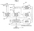
As shown in Fig. 1, an optical disk drive
101 includes a drive unit 102 that is hardware
resources for recording/reproducing information
on/from an optical disk, and further includes a
driver 103 of the drive unit 102. The drive unit
102 may not be an MRW drive unit but may a
conventional drive unit 102. On the other hand,
the driver 103 needs to a driver that complies with
the Mt. Rainier standard.
The drive unit 102 rotates an optical disk
104, which is an information recording medium such
as DVD+MRW or DVD+RW, and shines a laser beam on the
rotating optical disk 104 to perform the
recording/reproducing of information. For this
purpose, the drive unit 102 includes a motor 105 for
rotating the optical disk 104, an optical pickup 106
for shining laser light on the optical disk 104, and
a motor 107 for moving the optical pickup 106 in a
radial direction of the optical disk 104. The drive
unit 102 further includes a control system for
controlling the components described above.
As a control system, the drive unit 102
has a controller 108 that attends to the central
control of each component. The controller 108
controls a rotation control system 109, a pickup
control system 110, a motor control system 111, and
a signal processing system 112. The rotation
control system 109 controls the operation of the
motor 105, which drives and rotates the optical disk
104. The pickup control system 110 controls the
operation of the optical pickup 106, which shines
laser light on the optical disk 104. The motor
control system 111 controls the operation of the
motor 107, which moves the optical pickup 106 in a
radial direction of the optical disk 104.
The signal processing system 112 uses an
optical receiver device to detect laser light
reflected by the optical disk 104 as the laser light
is emitted by the optical pickup 106 under the
control of the pickup control system 110, and
processes the detected light signal. This signal
processing system 112 stores data read from the
optical disk 104 in a cache memory 113. The
controller 108 transfers the data stored in the
cache memory 113 to a host apparatus 115 connected
through an external interface 114.
The rotation control system 109, the
pickup control system 110, the motor control system
111, and the signal processing system 112, which
constitute the above-mentioned control system, may
be implemented as a digital circuit.
On the other hand, the controller 108
provided in the drive unit 102 is implemented by a
microcomputer, for example, and includes an
installed program 116 that serves as the driver 103
for information recording. Even if the program
116 for information recording is permanently stored
on recording medium such as a ROM in the controller
108, for example, it may additionally be stored in a
rewritable manner on a battery backup RAM, a
nonvolatile memory, etc.
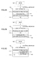
As another example of the storage of the
driver 103 of the drive unit 102, the program 116 of
the driver 103 for information recording may be
installed in a program storing section 117 provided
in the host apparatus 115, as shown in Fig. 2A.
Alternatively, the program 116 may be provided as
part of an OS 118 of the host apparatus 115 (refer
to Fig. 2B), or may be partially included in the OS
118 of the host apparatus 115 (refer to Fig. 2C).
In the configuration of the driver 103 of the drive
unit 102 illustrated in Figs. 2A through 2C, the
drive unit 102 and the host apparatus 115 together
make up an information recording system.
[Basic Operation]
In this configuration, the controller 108
controls and drives the drive unit 102 according to
the program 116 of the driver 103 for information
recording, thereby letting the optical pickup 106
irradiate the optical disk 104 with laser light.
Data is thus recorded on the optical disk 104
serving as an information recording medium
(corresponding to an information recording unit and
an information recording step).
In the case of the driver 103 complying
with the Mt. Rainier standard as in this embodiment,
defect management information and information about
formatting status are recorded in the MTA and the
STA of the optical disk 104, which is DVD+MRW. The
STA is a copy of what is stored in the MTA, and is
arranged in the data zone. When a defect is
detected in the DA during the recording of data, an
area in which data is recorded is reallocated to the
SA serving as a spare area (corresponding to a data
reallocating unit, a data reallocating step).
In this manner, the STA serving as a
defect management area and the SA serving as a spare
area are arranged in the data zone which is
accessible by the drive 102 having a conventional
configuration, thereby providing for the
conventional drive 102 to read the spare area.
The program 116 of the driver 103 for
information recording in this embodiment further
performs background formatting. In the background
formatting, a user making a formatting request is
notified of a formatting completion message after
recording only a portion of the lead-in zone, and
the remaining portions are recorded with dummy data
when there is no access from the user (i.e., a
background formatting unit and a background format
step).
After receiving the formatting completion
message, the user can record or reproduce data on a
random-access basis with respect to all the user
data area on the optical disk 104.
It is possible to take out the optical
disk 104 during the background formatting before the
recording of all the areas of the optical disk 104
is completed. When the optical disk 104 is ejected
during the background formatting, it is necessary
for the conventional drive to properly read the disk
having only a partial formatting. To this end, the
program 116 of the driver 103 for information
recording stores dummy data in unrecorded areas
intervening between recorded data. Further, the
program 116 of the driver 103 for information
recording records a TSTA from the position of the
LWA that is recorded with user data or recorded by
formatting, for the purpose of allowing the driver
103 to obtain defect management information. At the
end, a TLO is recorded, followed by the ejection of
the disk. Formatting may be resumed with respect
the disk that is ejected halfway through formatting
in this manner. When formatting is resumed, dummy
data is recorded from the position of the LWA.
These correspond to a background formatting resuming
unit and a background formatting resuming step.
In the case of DVD+MRW, on the other hand,
spare areas exist only in the SA1 and the SA2. The
SA2 may thus be used during the background
formatting. If the SA2 is used, it is necessary to
insert dummy data all the way from the position
where formatting is done to the position of the SA2
so as to allow the conventionally-configured drive
102 to read the data reallocated to the SA2. Since
the SA2 is situated at the very end of the user data
area, however, the optical disk 104 cannot be taken
out until formatting is complete if the SA2 is used
as a replacement. In order to avoid this in DVD+MRW,
as shown in Fig. 8B, data spared by (i.e.,
reallocated to) the SA2 is copied to the TSA2
following the formatted area, and, then, the disk is
ejected after recording the TSTA and the TLO
following the TSA2 (i.e., a temporary spare area
recording unit and a temporary spare area recording
step).
[Updating of Temporary Spare Area (TSA2)]
Depending on various conditions as will be
described, however, consistency between the SA2 and
the TSA2 may not be maintained. In such a case, a
user accessing the optical disk 104 may be given
incorrect information. In this embodiment, the
updating of the TSA2 is performed to obviate such a
problem.
Updating of a TSA2 performed by the driver
103 according to this embodiment will be described
with reference to Figs. 3, 4, and 9. In the
following, a description will be given by referring
to a case in which a user records data in the TSA2.
Fig. 3A is an illustrative drawing showing
a case in which a TSA2 is overwritten as a result of
the user recording of data in the partially
formatted optical disk 104 that is DVD+MRW. In Fig.
3A, a hatched region is an area that is overwritten,
which partially covers the TSA2.
The TSA2 will be left overwritten. When
the optical disk 104 having the TSA2 overwritten by
user data is inserted into the conventional drive
102, the conventional drive 102 gives incorrect
spare data to the user. Namely, when the TSA2 is
overwritten by user data during the process of
adding user data to the partially formatted optical
disk 104, the TSA2 will no longer correctly
represent the information of the SA2. If such an
optical disk 104 is inserted in the conventional
drive 102, incorrect information will be given to a
user.
In this embodiment, as shown in Fig. 3B,
the controller 108 attends to processing according
to the program 116 of the driver 103 for information
recording. When the TSA2 is overwritten by user
data, this processing records a TSA2 copied from the
SA2 on the optical disk 104 from the position of the
LWA at predetermined timing, and further records the
TSTA and the TLO following the TSA2 (corresponding
to a first updating unit).
This prevents the information of the TSA2
from being lost due to the overwriting user data
even if the user records data in the TSA2.
Here, Figs. 3A and 3B are provided to show
a situation in which the TSA2 is overwritten by user
data as a result of the user recording of data on
the partially formatted optical disk 104 that is
DVD+MRW. This embodiment successfully avoids a
problem caused by such a situation that the TSA2
does not properly reflect the information of the SA2.
A situation in which the TSA2 does not
correctly reflect the information of the SA2 is also
brought about when the data of the SA2 is updated.
Data of the SA2 may be updated when a user records
data in the areas reallocated to the SA2 or when a
new defect is found during the recording of user
data.
In this embodiment, even when such a
situation comes about, the controller 108 attends to
processing according to the program 116 of the
driver 103 for information recording. This
processing records a TSA2 copied from the SA2 on the
optical disk 104 from the position of the LWA at
predetermined timing, and further records the TSTA
and the TLO following the TSA2 (corresponding to a
second updating unit).
This prevents a situation in which the
TSA2 does not properly reflect the information of
the SA2.
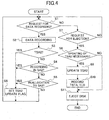
Fig. 4 is a flowchart showing a process of
updating a TSA2 performed by the controller 108
according to the program 116 of the driver 103 for
information recording. This process will be
described in the following.
When a data recording request is issued
from a user (step S1), data is recorded (step S2).
If an area requested by the user for data recording
is reallocated to the SA2, data is recorded in the
SA2.
A check is then made as to whether the
requested address is in the TSA2 (step S3). If it
is in the TSA2, a TSA2 update flag is set (step S6).
If the check at step S3 finds that the
requested address is not in the TSA2, a check is
further made as to whether the requested address has
been reallocated to the SA2 (step S4). If it has
been reallocated to the SA2, the TSA2 update flag is
set (step S6).
If the check at step S4 finds that the
requested address has not been reallocated to the
SA2, a check is further made as to whether recording
on the requested address has brought about
reallocation to the SA2 (step S5). If such
reallocation to the SA2 has occurred, the TSA2
update flag is set (step S6).
If it is ascertained at step S1 that there
is no data recording request from the user, a check
is made as to whether a request for ejecting the
optical disk 104 is made (step S7). If the request
for ejecting the optical disk 104 has been made (Yes
at step S7), it is checked whether the TSA2 update
flag is in the set status (step S8). If the TSA2
update flag is not in the set status, the disk is
discharged, and processing is brought to an end
(step S11). If the TSA2 update flag indicates the
set status, the TSA2 is newly recorded from the
position of the LWA (step S9). Then, the TSTA and
the TLO are recorded following the TSA2 (step S10),
and the disk is discharged (step S11) prior to the
closure of the processing.
In this embodiment as described above, the
updating of a TSA2 is performed at timing when a
request for ejecting the optical disk 104 is
received from the user. This prevents the
performance of a user request for data recording
from being degraded due to the updating of the TSA2
serving as a temporary spare area.
Alternatively, as another example, the
TSA2 may be updated at a time when a request for
formatting suspension is issued. In this case, the
check at step S7 for determining whether an eject
request is made is replaced by a check for
determining whether a request for formatting
suspension is made.
[Resuming of Background Formatting]
According to this embodiment, when a user
records data in the TSA2, the program 116 of the
driver 103 for information recording resumes
background formatting (corresponding to a first
resuming unit).
As shown in Fig. 3C, the resuming of
background formatting results in the recording of
dummy data being started from the position of the
LWA (i.e., the TLO start address). When the optical
disk 104 is to be taken out, the host apparatus 115
issues a request for formatting suspension. In
response to the request for formatting suspension,
the drive unit 102 starts recording a TSA2, a TSTA,
and a TLO from the new LWA before the discharge of
the optical disk 104. If there is no request for
formatting suspension from a user, the SA2, the STA
and the LO as would have been originally given will
be recorded.
In this manner, the loss of the TSA2
information due to the overwriting user data can be
prevented even when the user records data in the
TSA2.
Here, Fig. 3C is provided to show a
situation in which the TSA2 is overwritten by user
data as a result of the user recording of data on
the partially formatted optical disk 104 that is
DVD+MRW. This embodiment successfully avoids a
problem caused by such a situation that the TSA2
does not properly reflect the information of the SA2.
A situation in which the TSA2 does not
correctly reflect the information of the SA2 is also
brought about when the data of the SA2 is updated.
Data of the SA2 may be updated when a user records
data in the areas reallocated to the SA2 or when a
new defect is found during the recording of user
data.
In this embodiment, even when such a
situation comes about, the controller 108 attends to
processing according to the program 116 of the
driver 103 for information recording. This
processing resumes background formatting as shown in
Fig. 3C. That is, the. resuming of background
formatting starts by recording dummy data from the
position of the LWA (i.e., the TLO start address).
When the optical disk 104 is to be taken out, the
host apparatus 115 issues a request for formatting
suspension. In response to the request for
formatting suspension, the drive unit 102 starts
recording a TSA2, a TSTA, and a TLO from the new LWA
before the discharge of the optical disk 104
(corresponding to a second resuming unit).
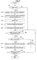
Fig. 5 is a flowchart showing a process of
resuming background formatting performed by the
controller 108 according to the program 116 of the
driver 103 for information recording. This process
will be described in the following.
When a data recording request is issued
from a user (step S21), data is recorded (step S22).
If an area requested by the user for data recording
is reallocated to the SA2, data is recorded in the
SA2.
A check is then made as to whether the
requested address is in the TSA2 (step S23). If it
is in the TSA2 (Yes at step S23), background
formatting is resumed (step S26).
If the requested address is not in the
TSA2 (No at step S23), a check is further made as to
whether the requested address has been reallocated
to the SA2 (step S24). If it has been reallocated
to the SA2 (Yes at step S24), background formatting
is resumed (step S26).
If the check at step S24 finds that the
requested address has not been reallocated to the
SA2 (No at step S24), a check is further made as to
whether recording on the requested address has
brought about reallocation to the SA2 (step S25).
If such reallocation to the SA2 has occurred (Yes at
step S25), background formatting is resumed (step
S26).
If it is ascertained at step S21 that
there is no data recording request from the user (No
at step S21), a check is made as to whether a
request for formatting suspension is made (step S27).
If the request for formatting suspension has been
made (Yes at step S27), it is checked whether
background formatting is underway (step S28).
If the check does not find that background
formatting is underway, processing is brought to an
end (No at step S28). If background formatting is
underway (Yes at step S28), the background
formatting is suspended (step S29). Then, the TSA2
is newly recorded from the position of the LWA (step
S30), and the TSTA and the TLO are recorded
following the TSA2 (step S31) prior to the closure
of the processing.
[Reproduction]
Fig. 6 is a flowchart showing a process of
reproducing data from an optical disk.
In reproduction, the drive unit 102 having
a conventional configuration and an MRW driver
(reader driver) work together to read data recorded
on the optical disk 104 that is an MRW disk.
The controller 108 operating based on the
program 116 of the driver 103 for information
recording checks whether the optical disk 104 is an
MRW disk (step S41). This check is made by
referring to a GAA (see Fig. 7) included in the DA
of the optical disk.
If the check finds that the optical disk
104 is not an MRW disk (No at step S41),
reproduction is commenced after awaiting a user
request for reproduction (steps S49-S52).
If it is ascertained that the optical disk
104 is an MRW disk (Yes at step S41) , search for a
TLO start address (step S42), search for a TSTA
start address (step S43), and reading of the TSTA
(step S44) are performed, thereby obtaining the TSA
and the TSA2 functioning as spare information (step
S45). The mounting of the MRW driver is then
completed (step S46). Reproduction starts after
awaiting a user request for reproduction (step S49-S52).
During reproduction, a check is made as to
whether there is any reallocated data in the DA
(step S48). If there is no reallocated data,
reproduction is continued until to the end (step
S52).
If there is reallocated data in the DA,
conversion to a reallocation address is made (step
S49). The reallocation address is then read (step
S50), and reproduction is continued until to the end
(step S52).
Further, the present invention is not
limited to these embodiments, but various variations
and modifications may be made without departing from
the scope of the present invention.
The present application is based on
Japanese priority application No. 2002-299335 filed
on October 11, 2002, Japanese priority application
No. 2002-308308 filed on October 23, 2002, and
Japanese priority application No. 2003-325195 filed
on September 17, 2003, with the Japanese Patent
Office, the entire contents of which are hereby
incorporated by reference.