EP1420365A2 - Coding method, coding apparatus and coding program of image information - Google Patents
Coding method, coding apparatus and coding program of image information Download PDFInfo
- Publication number
- EP1420365A2 EP1420365A2 EP03257076A EP03257076A EP1420365A2 EP 1420365 A2 EP1420365 A2 EP 1420365A2 EP 03257076 A EP03257076 A EP 03257076A EP 03257076 A EP03257076 A EP 03257076A EP 1420365 A2 EP1420365 A2 EP 1420365A2
- Authority
- EP
- European Patent Office
- Prior art keywords
- coding
- image information
- quantizing
- quantizing factor
- information
- Prior art date
- Legal status (The legal status is an assumption and is not a legal conclusion. Google has not performed a legal analysis and makes no representation as to the accuracy of the status listed.)
- Withdrawn
Links
Images



Classifications
-
- G—PHYSICS
- G06—COMPUTING OR CALCULATING; COUNTING
- G06T—IMAGE DATA PROCESSING OR GENERATION, IN GENERAL
- G06T9/00—Image coding
- G06T9/005—Statistical coding, e.g. Huffman, run length coding
Definitions
- the present invention relates to compression coding of image information.
- a motion predicting process such as DCT (Discrete Cosine Transform) is executed to the image data subjected to the coding. Then, obtained data is quantized by a suitable quantizing factor (quantizing bit number) of each frequency component, and is further codedby a variable length coding circuit.
- a suitable quantizing factor quantizing bit number
- allocation of the quantizing factor is executed so that a bit distribution of a low-frequency component is large because the low-frequency component is significant component for forming the image and the bit distribution of a high-frequency component is small. If a large quantizing factor is set, a coding quantity in each one-frame image is small. Conversely, if a small quantizing factor is set, the coding quantity in each one-frame image is large.
- the quantizing factor of the image data which would be input afterward was determined, and coding quantity allocation was executed. Namely, based on the average coding quantity of an image data portion for which the coding process had been completed before the current time (in the past) at each time during the coding process, setting of the quantizing factor for the coding process which would be executed after the current time (in the future) , i.e. , the coding quantity allocation, was executed.
- image data generally has scenes (or frames) which include large information quantities and small information quantities.
- the information quantity is large because image contents change largely, and the information quantity is not so large when similar image contents continue. Therefore, as described above, in a case that the coding quantity allocation is executed based on the average coding quantity until the current time in coding, the coding quantity obtained as a result of coding suddenly increases or decreases, if the image contents suddenly change as the scene changes.
- an overflow and an underflow may occur in a VBV buffer in which coded data is temporarily stored, or unnatural coding quantity adjustment may be executed so that the overflow and the underflow are prevented, e.g., the adj ustment which makes the quantizing factor suddenly change just before the overflow and the underflow occur.
- the present invention has been achieved in order to solve the above problems. It is an obj ect of this invention to execute proper coding quantity allocation through whole image data, based on a feature of the whole image data subjected to the coding.
- a coding method of image information according to the present invention includes a feature extraction process which quantizes and codes whole image information subjected to coding to extract feature information, a coding quantity predicting process which quantizes and codes the image information while changing a quantizing factor based on the feature information to determine a proper quantizing factor, and a coding process which utilizes a determined quantizing factor and quantizes and codes the image information to output a result as coded output data.
- the whole image information subj ected to the coding is quantized and coded to extract feature information in coding the image information.
- This process is regarded as a preparation which is executed in advance of an actual coding process.
- a coding quantity predicting process for determining the proper quantizing factor is executed by utilizing the feature information.
- the feature information is the information which indicates an information quantity according to image information contents subjected to the coding. If the quantizing factor is determined based on the feature information, the proper quantizing factor can be obtained in coding the image information.
- the coding quantity predicting process can be executed repeatedly until the proper quantizing factor is obtained.
- the actual coding process is executed. Namely, the image information subj ected to the coding is coded by utilizing the proper quantizing factor obtained in the coding quantity predicting process, and the result thereof is output as coded output data.
- the image information subjected to the coding is extracted in advance and the process in which the proper quantizing factor is determined based on the feature information is executed before the actual coding process, quantizing and coding which are suitable for the image information contents subjected to the coding and for the information quantity are executed. Therefore, failure of a VBV buffer during the coding process and sudden adjustment of the quantizing factor for preventing the failure of the VBV buffer can be avoided. Also, the image information can be coded by the proper coding quantity.
- the above coding quantity predicting process may include a factor setting process which sets the quantizing factor of each frame based on the feature information, an experimental coding process which utilizes a set quantizing factor and quantizes and codes of the image information to store result data of coding in a buffer, and a factor changing process which changes the quantizing factor of each frame when an overflow or an underflow occurs in the buffer.
- the proper quantizing factor is set of each frame, forming the image information, based on the feature information, and quantizing and coding are executed by utilizing the quantizing factor, it is determined whether the failure occurs in the buffer or not, i.e. , whether an overflow and an underflow occur or not. If the failure occurs in the buffer, the quantizing factor of each frame is adjusted, and it is determined whether the failure occurs in the buffer or not by executing quantizing and coding again. By repeating this process, it is possible that the quantizing factor which is suitable for the feature information of the image information and which does not make the buffer fail is obtained of each frame.
- the feature information may include a coding quantity of each frame obtained by coding the image information and information which specifies scenes constituting the image information.
- the experimental coding process may have a process which calculates a weighting value of each frame, and the factor changing process may set the quantizing factor changed based on the calculated weighting value and the quantizing factor which is utilized in a last experimental coding of the frame.
- the coding quantity of each frame and the information which specifies scenes constituting the image information are obtained as the feature information.
- the scene is a group of shots in the image information.
- the image information contents also change comparatively largely.
- a proper weighting value is set in each frame by utilizing the information which specifies the coding quantity and the scene of each frame, and a new quantizing factor is set by adjusting the quantizing factor utilized in the last experimental coding according to the weighting value. In that way, the quantizing factor which is suitable for the feature of the image information and which is allocated in each frame can be adjusted.
- the above coding method of the image information can be realized by executing a coding program, which is formed for executing a feature extraction process, the code quantity predicting process and the coding process, on a computer.
- a coding apparatus of image information which executes the above coding method include: a quantizing unit which quantizes the image information by a predetermined quantizing factor; a coding unit which codes quantizing data generated by the quantizing unit; a feature extraction unit which quantizes and codes the whole image information and extracts feature information; and a coding quantity predicting unit which quantizes and codes the image information while changing a quantizing factor and determines a proper quantizing factor, based on the feature information, wherein the quantizing unit and the coding unit utilizes the proper quantizing factor to quantize and code the image information and outputs a result as coded output data.
- FIG. 1 shows a schematic configuration of a coding apparatus for image data according to an embodiment of the present invention.
- a coding apparatus 1 performs compressive-coding of input image data D0 with a motion-compensation DCT system and outputs coded output data D4.
- the coding apparatus 1 includes a DCT unit 10, a quantizing unit 12, a coding unit 14, a VBV buffer 16 and a controller 20.
- the controller 20 has a memory 22 inside.
- the DCT unit 10 eliminates redundancy of the image data in a space domain by applying discrete cosine-conversion to the input image data.
- the data is shifted to low-frequency side if the image is converted into the data of the space frequency domain.
- DCT is usually executed per block of 8 ⁇ 8 pixel. As a result, factors of 8x8 are obtained as digital values. Data D1 thus obtained is supplied to the quantizing unit 12.
- the quantizing unit 12 quantizes the data D1 by the proper quantizing factor (quantizing bit number).
- the quantizing factor is appropriately determined according to a frequency component of the data D1.
- the quantizing factor of the low-frequency is large because the low-frequency component is significant component for forming the image, and the quantizing factor of the high-frequency is small because the high-frequency is less important than the low-frequency component.
- the quantizing factor in the quantizing unit 12 is controlled according to a controlling signal CS2 from the controller 20, which will be described in detail later.
- variable length coding is a coding method of eliminating the redundancy of the data by allocating a short code-length code to the data whose appearance probability is statistically high and allocating a long code-length code to the data whose appearance probability is low.
- Output data D3 of the coding unit 14 is temporarily stored in the VBV buffer 16, and is then output as the coded output data D4. It is preferred that the coded output data D4 is at a constant output rate because the data is supplied, as recording data, to a recording medium such as an optical disc.
- the VBV buffer 16 temporarily stores the output data D3 from the coding unit 14, and outputs the data at a constant rate.
- the VBV buffer 16 outputs the control signal CS1 which indicates the data quantity maintained inside to the controller 20.
- the controller 20 controls the quantizing factor in the quantizing unit 12 by utilizing the control signal CS1 which is supplied from the VBV buffer 16. Basically, since the output data D2 increases if the quantizing factor (bit number) in the quantizing unit 12 is large, the quantity of the output data D3 which is output from the coding unit 14, i.e., the coding quantity, becomes large. Conversely, if the quantizing factor in the quantizing unit 12 is small, the coding quantity becomes small. It is noted that the present invention is characterized in that the quantizing factor in the quantizing unit 12 is determined by utilizing not only the data quantity in the VBV buffer 16 but also the feature information of the input image data, which will be described in detail later.
- the coded output data D4 output from the VBV buffer 16 is also input to the controller 20.
- the controller 20 generates the feature information of the input image data based on the coded output data D4, and stores the information in the memory 22. Further, by utilizing the feature information to control the quantizing factor in the quantizing unit 12, the controller 20 allocates an optimum coding quantity to each frame of the input image data.
- FIG. 2 shows a flow of the coding process according to the present invention.
- the coding process for feature extraction of the input image data is executed before the actual coding process is executed.
- the coding process for the feature extraction is executed (step S1), and the feature information of the input image data is obtained.
- the coding quantity predicting process is executed (step S2) byutilizingthe feature information obtained in step S1. This process is to predict an optimum coding quantity for coding of the input image data and to set an optimum quantizing factor.
- the actual coding process is executed by utilizing the quantizing factor thus obtained (step S3). As a result that the proper coding process is executed, the coded output data is obtained.
- the coding process for the feature extraction is a process to examine the feature of the input image data, and the codingprocess is actually executed by utilizing the coding apparatus 1 shown in FIG. 1.
- the quantizing factor in the quantizing unit 12 is fixed to a constant value during the coding process for the feature extraction. If the quantizing factor is fixed, the information quantity of the input image data is judged by a single standard. Thus, a large changing portion and a small changing portion of the image contents of the input image data can be found. More concretely, if the controller 20 divides the coded output data D4 by each frame-unit, the coding quantity of each frame can be obtained.
- the scene changing portion is a portion at which the image data contents largely change, and the portion at which the scenes change in a movie and the other image corresponds to the scene changing portion, for example.
- the controller 20 can determine the portion, at which the coding quantity of each frame shows a larger change than the predetermined value, as the scene changing portion.
- the controller 20 generates, as the feature information, the information of (1) the coding quantity of each frame, (2) the information indicating the scene changingportion, and (3) the quantizing factor of each frame, and stores those information in the memory 22.
- the quantizing factor of each frame is the fixed value for all frames.
- FIG. 4A shows the example of the coding quantity variation during the coding process for the feature extraction.
- the horizontal axis indicates frame numbers of the input image data, which corresponds to time
- the vertical axis indicates the coding quantity of each frame.
- VBV buffer capacity is indicated by a broken line.
- a coding quantity per unit-time is constant, and an increasing rate of the coding quantity, which is an inclination of an increasing segment in the graph, is also constant. Since the coding quantity increases at the portion at which the information quantity in the input image data is large (the change of the image contents is large), a retained data quantity in the VBV buffer 16 becomes smaller than the capacity of the VBV buffer 16. As a result, the underflow may occur.
- the overflow may occur in a period that the information quantity of the input image data is small.
- a situation in which the overflow or the underflow is occurring is called the "failure of the VBV buffer". Since a buffer size of a decoder of the coded output data is set to the capacity of the VBV buffer 16, the coded output data can not be reproduced correctly by the decoder if the VBV buffer 16 fails. Thus, the occurrence of the overflow or the underflow means that the proper coding is not being executed. However, since the coding process for the feature extraction is the so-called experimental coding process in which the quantizing factor is fixed for the feature extraction of the input image data to be executed, occurrences of the overflow and the underflow is acceptable.
- the coding quantity predicting process (step S2) is executed.
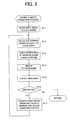
- FIG. 3 shows the coding quantity predicting process in detail.
- the coding quantity predicting process is to allocate the optimum coding quantity to each frame of the input image data by utilizing the feature information obtained during the coding process for the feature extraction, i.e., an experimental coding process which executes setting of the optimum quantizing factor of each frame. It is noted that the coding quantity predicting process is also executed by utilizing the feature information stored in the memory 22 and coding the input image data under control of the controller 20 shown in FIG. 1.
- the controller 20 divides the input image data D0 of each scene (step S11). Since the feature information obtained in step S1 includes the information of the scene changing portion, the input image data D0 can be divided, by utilizing the information, into plural groups of frame images forming scenes. Next, the controller 20 calculates the average coding quantity of each scene (step S12). Since the feature information includes the coding quantity of each frame, the average coding quantity of each frame can be calculated by adding up the coding quantity of plural frames forming each scene and dividing it by the frame number.
- significance of the frame corresponding to an ending portion in the scene is set low in each scene (step S13).
- the significance is determined by whether the frame largely affects the image contents in the input image data or not. Concretely, the significance affects the coding quantity allocated to the frame, i.e., the quantizing factor. Usually, during the scene change, an observer of reproduced image tends to have a strong impression of the image contents after the change. So, even if the quality of the frame image just before the scene change becomes worse slightly, there are fewadverse effects . Therefore, the significance of the frame at the ending portion of the scene is set low.
- Weighting value which is set to each frame, is a parameter indicating how much coding quantity should be allocated to the frame.
- a large weighting value is set to the frame whose information quantity is large and/or whose significance is high, and a small weighting value is set to the frame whose information quantity is small and/or whose significance is low.
- the weighting factors 1 to 5 are the predetermined values ranging between 0 and 1.
- the controller 20 After storing the weighting value, which is set of each frame in that way, in the memory 22, the controller 20 updates the quantizing factor of each frame according to the weighting value, and executes a coding simulation (experimental coding) (step S15).
- the update of the quantizing factor can be executed by multiplying the last value of the quantizing factor of each frame, which is obtained as the feature information and stored in the memory 22, by the weighting value of each frame.
- the coding simulation is a process which executes coding by the coding apparatus 1 by utilizing the quantizing factor actually determined.
- the controller 20 determines whether the VBV buffer 16 has failed or not based on the control signal CS1 from the VBV buffer 16, i . e . , whether the overflow or the underflow has occurred or not (step S16).
- the occurrence of the failure in the VBV buffer 16 means that the quantizing factor of each frame used in this coding simulation is inappropriate. Therefore, the controller 20 searches for the frame whose weighting value is minimum, and adjusts the quantizing factor of the frame (step S17).
- the reason why the quantizing factor is adjusted in the frame whose weighting value is minimum is to prevent a large effect to the image contents by adjusting the quantizing factor.
- the coding quantity is decreased by decreasing the quantizing factor in a case that the failure of the VBV buffer is the overflow, and the coding quantity is increased by increasing the quantizing factor in a case that the failure of the VBV buffer is the underflow.
- step S16 the process returns to step S12, and each frame is weighted again. And, by setting the quantizing factor, the coding simulation is repeated.
- step S16 the process goes ahead to step S3 shown in FIG. 2.
- FIG. 4B shows the example of variation of the coding quantity of each frame in the case that the failure does not occur in the VBV buffer. As is recognized by the comparison with FIG. 4A, since the overflow and the underflow do not occur, the coded output data at this time can be correctly decoded by the decoder.
- the coding apparatus 1 executes the actual coding process by utilizing the quantizing factor (step S3). If the failure of the VBV buffer is predicted during the actual coding process for some reason in spite of utilizing the quantizing factor determined in that way, the controller 20 can avoid the failure by adjusting the quantizing factor with using the control signal CS 1 from the VBV buffer 16.
- the coding process for the feature extraction of the input image data is executed, and the feature information of the input image data is obtained.
- weighting value is adjusted in the coding quantizing predicting process, and at the same time, the coding simulation is executed so that the optimum quantizing factor is set.
Landscapes
- Engineering & Computer Science (AREA)
- Multimedia (AREA)
- Physics & Mathematics (AREA)
- General Physics & Mathematics (AREA)
- Theoretical Computer Science (AREA)
- Compression Or Coding Systems Of Tv Signals (AREA)
- Compression Of Band Width Or Redundancy In Fax (AREA)
- Signal Processing For Digital Recording And Reproducing (AREA)
- Compression, Expansion, Code Conversion, And Decoders (AREA)
- Television Signal Processing For Recording (AREA)
Abstract
Description
Claims (5)
- A coding method of image information comprising:a feature extraction process which quantizes and codes whole image information subjected to coding to extract feature information;a coding quantity predicting process which quantizes and codes the image information, while changing a quantizing factor based on the feature information, to determine a proper quantizing factor; anda coding process which utilizes a determined quantizing factor and quantizes and codes the image information to output a result as coded output data.
- The coding method according to claim 1, wherein the coding quantity predicting process comprises:a factor setting process which sets the quantizing factor of each frame based on the feature information;an experimental coding process which utilizes a set quantizing factor and quantizes and codes of the image information to store result data of coding in a buffer (16); anda factor changing process which changes the quantizing factor of each frame when an overflow or an underflow occurs in the buffer.
- The coding method according to claim 2:
wherein the feature information comprises a coding quantity of each frame obtained by coding the image information, and information which specifies scenes constituting the image information;
wherein the experimental coding process has a process which calculates a weighting value of each frame; and
wherein the factor changing process changes the quantizing factor, based on the calculated weighting value and the quantizing factor which is utilized in a previous experimental coding of the frame. - A coding program of image information which makes a computer execute, by executing on the computer:a feature extraction process which quantizes and codes whole image information subj ected to coding and extracts feature information;a coding quantity predicting process which quantizes and codes the image information, while changing a quantizing factor and determines a proper quantizing factor, based on the feature information; anda coding process which utilizes the proper quantizing factor and quantizes and codes the image information to output a result as coded output data.
- A coding apparatus (1) of image information comprising:wherein the quantizing unit (12) and the coding unit (14) utilizes the proper quantizing factor to quantize and code the image information and outputs a result as coded output data.a quantizing unit (12) which quantizes the image information by a predetermined quantizing factor;a coding unit (14) which codes quantizing data generated by the quantizing unit;a feature extraction unit (20) which quantizes and codes the whole image information and extracts feature information; anda coding quantity predicting unit (20) which quantizes and codes the image information, while changing a quantizing factor and determines a proper quantizing factor, based on the feature information,
Applications Claiming Priority (2)
| Application Number | Priority Date | Filing Date | Title |
|---|---|---|---|
| JP2002332137 | 2002-11-15 | ||
| JP2002332137A JP2004166128A (en) | 2002-11-15 | 2002-11-15 | Method, device and program for coding image information |
Publications (2)
| Publication Number | Publication Date |
|---|---|
| EP1420365A2 true EP1420365A2 (en) | 2004-05-19 |
| EP1420365A3 EP1420365A3 (en) | 2004-06-23 |
Family
ID=32171413
Family Applications (1)
| Application Number | Title | Priority Date | Filing Date |
|---|---|---|---|
| EP20030257076 Withdrawn EP1420365A3 (en) | 2002-11-15 | 2003-11-10 | Coding method, coding apparatus and coding program of image information |
Country Status (3)
| Country | Link |
|---|---|
| US (1) | US20040096113A1 (en) |
| EP (1) | EP1420365A3 (en) |
| JP (1) | JP2004166128A (en) |
Cited By (1)
| Publication number | Priority date | Publication date | Assignee | Title |
|---|---|---|---|---|
| CN103096081A (en) * | 2013-01-15 | 2013-05-08 | 深圳市中瀛鑫科技股份有限公司 | Handling method of transformation coefficient and method and module and coder of wavelet transformation coding |
Families Citing this family (12)
| Publication number | Priority date | Publication date | Assignee | Title |
|---|---|---|---|---|
| US7042943B2 (en) | 2002-11-08 | 2006-05-09 | Apple Computer, Inc. | Method and apparatus for control of rate-distortion tradeoff by mode selection in video encoders |
| US20040141874A1 (en) * | 2003-01-15 | 2004-07-22 | Phillip Mullinax | System and apparatus for ozonating air and water for animal confinement houses |
| US8406293B2 (en) * | 2004-06-27 | 2013-03-26 | Apple Inc. | Multi-pass video encoding based on different quantization parameters |
| US8005139B2 (en) | 2004-06-27 | 2011-08-23 | Apple Inc. | Encoding with visual masking |
| EP1762093A4 (en) * | 2004-06-27 | 2011-06-29 | Apple Inc | Multi-pass video encoding |
| US7936938B2 (en) * | 2004-09-07 | 2011-05-03 | Canon Kabushiki Kaisha | Methods and devices for encoding a digital image signal and associated decoding methods and devices |
| US8208536B2 (en) | 2005-04-28 | 2012-06-26 | Apple Inc. | Method and apparatus for encoding using single pass rate controller |
| JP4644097B2 (en) * | 2005-10-31 | 2011-03-02 | 富士通セミコンダクター株式会社 | A moving picture coding program, a program storage medium, and a coding apparatus. |
| JP4668767B2 (en) * | 2005-10-31 | 2011-04-13 | 富士通セミコンダクター株式会社 | Moving picture coding apparatus and moving picture coding program |
| WO2008047714A1 (en) * | 2006-10-16 | 2008-04-24 | Panasonic Corporation | Code conversion method, transcoder, and integrated circuit thereof |
| JP2008236333A (en) * | 2007-03-20 | 2008-10-02 | Toshiba Corp | Video encoding apparatus and video encoding method |
| CN111724295B (en) * | 2019-03-18 | 2024-05-14 | 芯原微电子(成都)有限公司 | Collaborative access method and system for external memory and collaborative access architecture |
Family Cites Families (5)
| Publication number | Priority date | Publication date | Assignee | Title |
|---|---|---|---|---|
| US5677969A (en) * | 1995-02-23 | 1997-10-14 | Motorola, Inc. | Method, rate controller, and system for preventing overflow and underflow of a decoder buffer in a video compression system |
| US6415057B1 (en) * | 1995-04-07 | 2002-07-02 | Sony Corporation | Method and apparatus for selective control of degree of picture compression |
| US5677689A (en) * | 1995-08-31 | 1997-10-14 | Yovanof; Gregory S. | Fixed rate JPEG compliant still image compression |
| FI107496B (en) * | 1997-07-18 | 2001-08-15 | Nokia Mobile Phones Ltd | Image Compressor Call |
| JP2002252770A (en) * | 2001-02-22 | 2002-09-06 | Matsushita Graphic Communication Systems Inc | Classification method for image information, image coding method, and image coder |
-
2002
- 2002-11-15 JP JP2002332137A patent/JP2004166128A/en not_active Abandoned
-
2003
- 2003-11-10 EP EP20030257076 patent/EP1420365A3/en not_active Withdrawn
- 2003-11-17 US US10/713,032 patent/US20040096113A1/en not_active Abandoned
Cited By (1)
| Publication number | Priority date | Publication date | Assignee | Title |
|---|---|---|---|---|
| CN103096081A (en) * | 2013-01-15 | 2013-05-08 | 深圳市中瀛鑫科技股份有限公司 | Handling method of transformation coefficient and method and module and coder of wavelet transformation coding |
Also Published As
| Publication number | Publication date |
|---|---|
| EP1420365A3 (en) | 2004-06-23 |
| JP2004166128A (en) | 2004-06-10 |
| US20040096113A1 (en) | 2004-05-20 |
Similar Documents
| Publication | Publication Date | Title |
|---|---|---|
| EP0535960B1 (en) | Coding signal processor | |
| KR100505699B1 (en) | Encoding rate controller of video encoder providing for qualitative display using real time variable bit-rate control, video data transmission system having it and method thereof | |
| US5134476A (en) | Video signal encoding with bit rate control | |
| KR101012600B1 (en) | Rate control using image-based lookahead window | |
| US5677969A (en) | Method, rate controller, and system for preventing overflow and underflow of a decoder buffer in a video compression system | |
| KR950004118B1 (en) | Quantization Step Size Determination Method and Apparatus | |
| US7409097B2 (en) | Video encoding using variable bit rates | |
| KR100756596B1 (en) | Video data encoder and video data encoding method | |
| EP1096803A2 (en) | Video encoder and method for adjusting quantization step in real time | |
| US20130177074A1 (en) | Image Processing Apparatus | |
| US5550595A (en) | Apparatus and method for motion estimation with enhanced camera interface | |
| US8396120B2 (en) | Robust single-pass variable bit rate encoding | |
| US20040096113A1 (en) | Coding method, coding apparatus and coding program of image information | |
| JPH1075451A (en) | Video data compression apparatus and method | |
| US20050201460A1 (en) | System and method for controlling bit rate of an image | |
| JP2001251629A (en) | Video encoding device for scene characteristics detection | |
| US6137946A (en) | Picture editing apparatus and method using virtual buffer estimation | |
| RU2485711C2 (en) | Method of controlling video bitrate, apparatus for controlling video bitrate, machine-readable recording medium on which video bitrate control program is recorded | |
| US8780977B2 (en) | Transcoder | |
| JP2004328150A (en) | Video encoding apparatus and method | |
| JPH09149412A (en) | Video data compression method | |
| JP3218994B2 (en) | Image coding method and apparatus | |
| JPH042291A (en) | Coding device and coding method for picture data | |
| US7606436B2 (en) | Image encoding apparatus and quantization control method | |
| JPH09261638A (en) | Image coding device |
Legal Events
| Date | Code | Title | Description |
|---|---|---|---|
| PUAI | Public reference made under article 153(3) epc to a published international application that has entered the european phase |
Free format text: ORIGINAL CODE: 0009012 |
|
| PUAL | Search report despatched |
Free format text: ORIGINAL CODE: 0009013 |
|
| AK | Designated contracting states |
Kind code of ref document: A2 Designated state(s): AT BE BG CH CY CZ DE DK EE ES FI FR GB GR HU IE IT LI LU MC NL PT RO SE SI SK TR |
|
| AX | Request for extension of the european patent |
Extension state: AL LT LV MK |
|
| AK | Designated contracting states |
Kind code of ref document: A3 Designated state(s): AT BE BG CH CY CZ DE DK EE ES FI FR GB GR HU IE IT LI LU MC NL PT RO SE SI SK TR |
|
| AX | Request for extension of the european patent |
Extension state: AL LT LV MK |
|
| 17P | Request for examination filed |
Effective date: 20041209 |
|
| AKX | Designation fees paid |
Designated state(s): DE FR GB |
|
| 17Q | First examination report despatched |
Effective date: 20050511 |
|
| STAA | Information on the status of an ep patent application or granted ep patent |
Free format text: STATUS: THE APPLICATION IS DEEMED TO BE WITHDRAWN |
|
| 18D | Application deemed to be withdrawn |
Effective date: 20050922 |