EP1420234A1 - Method for selecting a binder for a thermal indicator in a gas turbine system - Google Patents
Method for selecting a binder for a thermal indicator in a gas turbine system Download PDFInfo
- Publication number
- EP1420234A1 EP1420234A1 EP03257148A EP03257148A EP1420234A1 EP 1420234 A1 EP1420234 A1 EP 1420234A1 EP 03257148 A EP03257148 A EP 03257148A EP 03257148 A EP03257148 A EP 03257148A EP 1420234 A1 EP1420234 A1 EP 1420234A1
- Authority
- EP
- European Patent Office
- Prior art keywords
- substrate
- indicator
- binder
- temperature
- turbine
- Prior art date
- Legal status (The legal status is an assumption and is not a legal conclusion. Google has not performed a legal analysis and makes no representation as to the accuracy of the status listed.)
- Granted
Links
- 239000011230 binding agent Substances 0.000 title claims abstract description 115
- 238000000034 method Methods 0.000 title claims abstract description 47
- 239000000758 substrate Substances 0.000 claims abstract description 110
- 238000012544 monitoring process Methods 0.000 claims abstract description 38
- 230000006866 deterioration Effects 0.000 claims abstract description 16
- 239000002245 particle Substances 0.000 claims description 33
- 230000006378 damage Effects 0.000 claims description 10
- 238000004891 communication Methods 0.000 claims description 7
- 239000012530 fluid Substances 0.000 claims description 6
- 230000008018 melting Effects 0.000 claims description 6
- 238000002844 melting Methods 0.000 claims description 6
- 239000007789 gas Substances 0.000 description 50
- 239000000463 material Substances 0.000 description 19
- 239000000203 mixture Substances 0.000 description 16
- 238000000576 coating method Methods 0.000 description 15
- MWUXSHHQAYIFBG-UHFFFAOYSA-N Nitric oxide Chemical compound O=[N] MWUXSHHQAYIFBG-UHFFFAOYSA-N 0.000 description 12
- 239000011248 coating agent Substances 0.000 description 12
- XLYOFNOQVPJJNP-UHFFFAOYSA-N water Substances O XLYOFNOQVPJJNP-UHFFFAOYSA-N 0.000 description 10
- 239000012720 thermal barrier coating Substances 0.000 description 9
- 230000005496 eutectics Effects 0.000 description 7
- KWGKDLIKAYFUFQ-UHFFFAOYSA-M lithium chloride Chemical compound [Li+].[Cl-] KWGKDLIKAYFUFQ-UHFFFAOYSA-M 0.000 description 6
- 239000000155 melt Substances 0.000 description 6
- 230000003628 erosive effect Effects 0.000 description 5
- 229910052693 Europium Inorganic materials 0.000 description 4
- 229910020451 K2SiO3 Inorganic materials 0.000 description 4
- OAICVXFJPJFONN-UHFFFAOYSA-N Phosphorus Chemical compound [P] OAICVXFJPJFONN-UHFFFAOYSA-N 0.000 description 4
- 230000007797 corrosion Effects 0.000 description 4
- 238000005260 corrosion Methods 0.000 description 4
- 230000002939 deleterious effect Effects 0.000 description 4
- OGPBJKLSAFTDLK-UHFFFAOYSA-N europium atom Chemical compound [Eu] OGPBJKLSAFTDLK-UHFFFAOYSA-N 0.000 description 4
- 239000000374 eutectic mixture Substances 0.000 description 4
- 239000012255 powdered metal Substances 0.000 description 4
- XEEYBQQBJWHFJM-UHFFFAOYSA-N Iron Chemical group [Fe] XEEYBQQBJWHFJM-UHFFFAOYSA-N 0.000 description 3
- 229910020489 SiO3 Inorganic materials 0.000 description 3
- 239000000919 ceramic Substances 0.000 description 3
- 238000002485 combustion reaction Methods 0.000 description 3
- 239000003269 fluorescent indicator Substances 0.000 description 3
- 238000010438 heat treatment Methods 0.000 description 3
- 229910052751 metal Inorganic materials 0.000 description 3
- 239000002184 metal Substances 0.000 description 3
- 230000001681 protective effect Effects 0.000 description 3
- 239000002520 smart material Substances 0.000 description 3
- 229910001388 sodium aluminate Inorganic materials 0.000 description 3
- 230000007704 transition Effects 0.000 description 3
- KEQXNNJHMWSZHK-UHFFFAOYSA-L 1,3,2,4$l^{2}-dioxathiaplumbetane 2,2-dioxide Chemical compound [Pb+2].[O-]S([O-])(=O)=O KEQXNNJHMWSZHK-UHFFFAOYSA-L 0.000 description 2
- 229910000951 Aluminide Inorganic materials 0.000 description 2
- 229910001477 LaPO4 Inorganic materials 0.000 description 2
- PXHVJJICTQNCMI-UHFFFAOYSA-N Nickel Chemical group [Ni] PXHVJJICTQNCMI-UHFFFAOYSA-N 0.000 description 2
- FAPWRFPIFSIZLT-UHFFFAOYSA-M Sodium chloride Chemical compound [Na+].[Cl-] FAPWRFPIFSIZLT-UHFFFAOYSA-M 0.000 description 2
- 229910052771 Terbium Inorganic materials 0.000 description 2
- 238000004458 analytical method Methods 0.000 description 2
- 229910052924 anglesite Inorganic materials 0.000 description 2
- FLJPGEWQYJVDPF-UHFFFAOYSA-L caesium sulfate Chemical compound [Cs+].[Cs+].[O-]S([O-])(=O)=O FLJPGEWQYJVDPF-UHFFFAOYSA-L 0.000 description 2
- 239000013522 chelant Substances 0.000 description 2
- 238000006243 chemical reaction Methods 0.000 description 2
- 239000000567 combustion gas Substances 0.000 description 2
- 238000009792 diffusion process Methods 0.000 description 2
- 230000000694 effects Effects 0.000 description 2
- 238000010285 flame spraying Methods 0.000 description 2
- 239000000446 fuel Substances 0.000 description 2
- YBMRDBCBODYGJE-UHFFFAOYSA-N germanium dioxide Chemical compound O=[Ge]=O YBMRDBCBODYGJE-UHFFFAOYSA-N 0.000 description 2
- 238000012423 maintenance Methods 0.000 description 2
- 229910044991 metal oxide Inorganic materials 0.000 description 2
- 150000004706 metal oxides Chemical class 0.000 description 2
- 230000001473 noxious effect Effects 0.000 description 2
- 230000003647 oxidation Effects 0.000 description 2
- 238000007254 oxidation reaction Methods 0.000 description 2
- SIWVEOZUMHYXCS-UHFFFAOYSA-N oxo(oxoyttriooxy)yttrium Chemical compound O=[Y]O[Y]=O SIWVEOZUMHYXCS-UHFFFAOYSA-N 0.000 description 2
- -1 phosphor compound Chemical class 0.000 description 2
- 238000007750 plasma spraying Methods 0.000 description 2
- BASFCYQUMIYNBI-UHFFFAOYSA-N platinum Chemical compound [Pt] BASFCYQUMIYNBI-UHFFFAOYSA-N 0.000 description 2
- BWHMMNNQKKPAPP-UHFFFAOYSA-L potassium carbonate Chemical compound [K+].[K+].[O-]C([O-])=O BWHMMNNQKKPAPP-UHFFFAOYSA-L 0.000 description 2
- 239000011253 protective coating Substances 0.000 description 2
- 238000007789 sealing Methods 0.000 description 2
- 239000002002 slurry Substances 0.000 description 2
- 238000004611 spectroscopical analysis Methods 0.000 description 2
- 238000001228 spectrum Methods 0.000 description 2
- 239000000126 substance Substances 0.000 description 2
- 229910004829 CaWO4 Inorganic materials 0.000 description 1
- 229910004613 CdTe Inorganic materials 0.000 description 1
- 229910052684 Cerium Inorganic materials 0.000 description 1
- 229910004664 Cerium(III) chloride Inorganic materials 0.000 description 1
- 229910021562 Chromium(II) fluoride Inorganic materials 0.000 description 1
- 229910021556 Chromium(III) chloride Inorganic materials 0.000 description 1
- 229910004650 HoF3 Inorganic materials 0.000 description 1
- 239000004831 Hot glue Substances 0.000 description 1
- 229910020246 KBO2 Inorganic materials 0.000 description 1
- 229910002226 La2O2 Inorganic materials 0.000 description 1
- 229910001216 Li2S Inorganic materials 0.000 description 1
- 229910013482 LuF3 Inorganic materials 0.000 description 1
- 229910019752 Mg2Si Inorganic materials 0.000 description 1
- 229910000831 Steel Inorganic materials 0.000 description 1
- 206010047513 Vision blurred Diseases 0.000 description 1
- 229910045601 alloy Inorganic materials 0.000 description 1
- 239000000956 alloy Substances 0.000 description 1
- PNEYBMLMFCGWSK-UHFFFAOYSA-N aluminium oxide Inorganic materials [O-2].[O-2].[O-2].[Al+3].[Al+3] PNEYBMLMFCGWSK-UHFFFAOYSA-N 0.000 description 1
- 229910052785 arsenic Inorganic materials 0.000 description 1
- 238000003556 assay Methods 0.000 description 1
- NKQIMNKPSDEDMO-UHFFFAOYSA-L barium bromide Chemical compound [Br-].[Br-].[Ba+2] NKQIMNKPSDEDMO-UHFFFAOYSA-L 0.000 description 1
- 229910001620 barium bromide Inorganic materials 0.000 description 1
- 230000008901 benefit Effects 0.000 description 1
- QCUOBSQYDGUHHT-UHFFFAOYSA-L cadmium sulfate Chemical compound [Cd+2].[O-]S([O-])(=O)=O QCUOBSQYDGUHHT-UHFFFAOYSA-L 0.000 description 1
- 229910000369 cadmium(II) sulfate Inorganic materials 0.000 description 1
- 238000005524 ceramic coating Methods 0.000 description 1
- 229910010293 ceramic material Inorganic materials 0.000 description 1
- VYLVYHXQOHJDJL-UHFFFAOYSA-K cerium trichloride Chemical compound Cl[Ce](Cl)Cl VYLVYHXQOHJDJL-UHFFFAOYSA-K 0.000 description 1
- 230000008859 change Effects 0.000 description 1
- 229910052804 chromium Inorganic materials 0.000 description 1
- QSWDMMVNRMROPK-UHFFFAOYSA-K chromium(3+) trichloride Chemical compound [Cl-].[Cl-].[Cl-].[Cr+3] QSWDMMVNRMROPK-UHFFFAOYSA-K 0.000 description 1
- 239000011636 chromium(III) chloride Substances 0.000 description 1
- RNFYGEKNFJULJY-UHFFFAOYSA-L chromium(ii) fluoride Chemical compound [F-].[F-].[Cr+2] RNFYGEKNFJULJY-UHFFFAOYSA-L 0.000 description 1
- 229910017052 cobalt Inorganic materials 0.000 description 1
- 239000010941 cobalt Chemical group 0.000 description 1
- GUTLYIVDDKVIGB-UHFFFAOYSA-N cobalt atom Chemical group [Co] GUTLYIVDDKVIGB-UHFFFAOYSA-N 0.000 description 1
- 150000001875 compounds Chemical class 0.000 description 1
- 239000012141 concentrate Substances 0.000 description 1
- PDZKZMQQDCHTNF-UHFFFAOYSA-M copper(1+);thiocyanate Chemical compound [Cu+].[S-]C#N PDZKZMQQDCHTNF-UHFFFAOYSA-M 0.000 description 1
- BERDEBHAJNAUOM-UHFFFAOYSA-N copper(I) oxide Inorganic materials [Cu]O[Cu] BERDEBHAJNAUOM-UHFFFAOYSA-N 0.000 description 1
- KRFJLUBVMFXRPN-UHFFFAOYSA-N cuprous oxide Chemical compound [O-2].[Cu+].[Cu+] KRFJLUBVMFXRPN-UHFFFAOYSA-N 0.000 description 1
- 230000008021 deposition Effects 0.000 description 1
- 238000001514 detection method Methods 0.000 description 1
- 238000010586 diagram Methods 0.000 description 1
- 239000012153 distilled water Substances 0.000 description 1
- 230000005684 electric field Effects 0.000 description 1
- 230000005670 electromagnetic radiation Effects 0.000 description 1
- 238000000921 elemental analysis Methods 0.000 description 1
- 229910052635 ferrosilite Inorganic materials 0.000 description 1
- 238000010304 firing Methods 0.000 description 1
- 231100001261 hazardous Toxicity 0.000 description 1
- 229910052742 iron Inorganic materials 0.000 description 1
- 238000004020 luminiscence type Methods 0.000 description 1
- AEDROEGYZIARPU-UHFFFAOYSA-K lutetium(iii) chloride Chemical compound Cl[Lu](Cl)Cl AEDROEGYZIARPU-UHFFFAOYSA-K 0.000 description 1
- 229910052748 manganese Inorganic materials 0.000 description 1
- 229910052960 marcasite Inorganic materials 0.000 description 1
- 238000004949 mass spectrometry Methods 0.000 description 1
- 229910052651 microcline Inorganic materials 0.000 description 1
- 229910052759 nickel Chemical group 0.000 description 1
- 231100000252 nontoxic Toxicity 0.000 description 1
- 230000003000 nontoxic effect Effects 0.000 description 1
- 125000002524 organometallic group Chemical group 0.000 description 1
- 229910052652 orthoclase Inorganic materials 0.000 description 1
- 230000001151 other effect Effects 0.000 description 1
- 239000013618 particulate matter Substances 0.000 description 1
- 230000000737 periodic effect Effects 0.000 description 1
- 229910052697 platinum Inorganic materials 0.000 description 1
- 229910000027 potassium carbonate Inorganic materials 0.000 description 1
- 230000008569 process Effects 0.000 description 1
- NIFIFKQPDTWWGU-UHFFFAOYSA-N pyrite Chemical compound [Fe+2].[S-][S-] NIFIFKQPDTWWGU-UHFFFAOYSA-N 0.000 description 1
- 229910052683 pyrite Inorganic materials 0.000 description 1
- 230000005855 radiation Effects 0.000 description 1
- 230000002285 radioactive effect Effects 0.000 description 1
- 230000009257 reactivity Effects 0.000 description 1
- 230000008439 repair process Effects 0.000 description 1
- 230000004044 response Effects 0.000 description 1
- 238000005070 sampling Methods 0.000 description 1
- 229910052654 sanidine Inorganic materials 0.000 description 1
- 239000011780 sodium chloride Substances 0.000 description 1
- 239000010959 steel Substances 0.000 description 1
- 230000002277 temperature effect Effects 0.000 description 1
- GZCRRIHWUXGPOV-UHFFFAOYSA-N terbium atom Chemical compound [Tb] GZCRRIHWUXGPOV-UHFFFAOYSA-N 0.000 description 1
- FDIFPFNHNADKFC-UHFFFAOYSA-K trifluoroholmium Chemical compound F[Ho](F)F FDIFPFNHNADKFC-UHFFFAOYSA-K 0.000 description 1
- 229910052844 willemite Inorganic materials 0.000 description 1
Images


Classifications
-
- G—PHYSICS
- G01—MEASURING; TESTING
- G01K—MEASURING TEMPERATURE; MEASURING QUANTITY OF HEAT; THERMALLY-SENSITIVE ELEMENTS NOT OTHERWISE PROVIDED FOR
- G01K11/00—Measuring temperature based upon physical or chemical changes not covered by groups G01K3/00, G01K5/00, G01K7/00 or G01K9/00
- G01K11/06—Measuring temperature based upon physical or chemical changes not covered by groups G01K3/00, G01K5/00, G01K7/00 or G01K9/00 using melting, freezing, or softening
-
- F—MECHANICAL ENGINEERING; LIGHTING; HEATING; WEAPONS; BLASTING
- F02—COMBUSTION ENGINES; HOT-GAS OR COMBUSTION-PRODUCT ENGINE PLANTS
- F02C—GAS-TURBINE PLANTS; AIR INTAKES FOR JET-PROPULSION PLANTS; CONTROLLING FUEL SUPPLY IN AIR-BREATHING JET-PROPULSION PLANTS
- F02C9/00—Controlling gas-turbine plants; Controlling fuel supply in air- breathing jet-propulsion plants
Definitions
- the invention relates to a method, article and system for monitoring a combustion system with a selected binder. More particularly, the invention is directed to an indicator in a selected binder.
- a gas turbine engine includes in serial flow communication, one or more compressors followed in turn by combustors and high and low pressure turbines disposed about a longitudinal axial centerline within an annular outer casing.
- the compressors are driven by the turbine to compress air, which is mixed with fuel and ignited in the combustors to generate hot combustion gases.
- the combustion gases flow downstream through the high and low pressure turbines to extract energy to drive the compressors to produce output power either as shaft power or thrust.
- a thermal barrier coating system includes an environmentally-resistant bond coating and a thermal barrier coating (TBC) of a ceramic material applied as a topcoat over a bond coat.
- Bond coats are typically formed of an oxidation-resistant alloy such as MCrAIY where M is iron, cobalt and/or nickel, or a diffusion aluminide or platinum aluminide. At high temperature, these bond coats form an oxide layer or scale that chemically bonds the ceramic layer to the underlying component.
- Maximum power output of a gas turbine is achieved by heating the gas flowing through the combustion section to as high a temperature as is feasible.
- the heated gas also heats the various turbine components as it flows through the turbine. These components may be critical components that have a direct impact on the operation and efficiency of the turbine. With time, continued flow of excessively high temperature air wears down the component protective TBC layer.
- So called "smart materials” have been proposed to monitor and detect on-line wear due to high temperature operation and other effects of operation in a corrosive environment.
- a smart material senses a change in an environment, and then using a feedback system, makes a useful response.
- Hanneman, U.S. 4,327,155 and Siemers et al., U.S. 4,327,120 provide examples of smart materials.
- Hanneman teaches a substrate that has a protective metallic or ceramic coating. The substrate is subject to a high degree of surface erosion that eventually wears away the protective coating.
- the protective coating can be periodically renewed or replaced by plasma or flame spraying with a powdered metal or a powdered metal oxide blend.
- Hanneman proposes a smart coating that includes a UV sensitive phosphor.
- the UV sensitive material-containing coating emits UV sensitive material as it wears. Monitoring the emission of UV sensitive material can indicate when additional plasma or flame spraying of the metal substrate with powdered metal or powdered metal oxide should be undertaken. Siemers et al. teaches that the particulate size of the phosphor component of the UV sensitive indicating material should be sized according to an Energy of Melting formula.
- the Hanneman and Siemers et al. materials can be used in systems to estimate parts life.
- life monitoring takes the form of detecting UV sensitive material and relating a quantity of detected material over a period of time to a data base that includes relationships of material over time with coating wear.
- detected material over time and wear relationship data is not available for new systems or, for that matter, for most old systems.
- known indicators are applied to a component in a non-uniform manner. In this case, detected indicators do not accurately reflect wear or other operational effects.
- Some coating life monitoring methods are based on average effects of stress and temperature profiles of all the parts. These methods are unable to focus on individual parts because they do not take into account the exposure circumstances of a particular part or section of a part. A particular part or section of a part may uniquely encounter wear or damage caused by foreign objects, varying operating conditions from site to site and occasional turbine over-firing. Such circumstances can uniquely influence coating and part life.
- the present invention provides a method, article and system to sense and monitor indicator emissions from a coating to provide accurate, particular location information to determine wear, maintenance scheduling and to reduce noxious emissions.
- the invention provides a method for forming a monitoring deposit on a substrate, comprising determining a temperature range to subject the substrate to provide a high temperature of operation up to less than a critical substrate deterioration temperature; selecting a binder to monitor temperature by emitting an indicator within the determined temperature range; combining the indicator and the binder; and applying the combined indicator and binder to the substrate to form the monitoring deposit.
- the invention relates to an article, comprising a substrate; and a combined indicator and binder applied into the substrate, wherein the binder emits the indicator within a temperature range determined to subject the substrate to high temperature operation up to less than a critical substrate deterioration temperature.
- the invention in another embodiment, relates to a method of monitoring a gas turbine system comprising selecting a binder to monitor temperature by emitting an indicator within a temperature range determined to permit subjecting a substrate in the system to high temperature operation up to less than a critical turbine substrate deterioration temperature; combining the indicator and the binder; and applying the combined indicator and binder to the substrate to form the monitoring deposit.
- the invention is a system for monitoring a gas turbine engine comprising a substrate; and a combined indicator and binder applied onto the substrate, wherein the binder emits the indicator within a temperature range determined to permit subjecting the substrate to high temperature operation up to less than a critical substrate deterioration temperature.
- luminescence means a light emission that cannot be attributed merely to the temperature of an emitting body, but results from such causes as chemical reactions at ordinary temperatures, electron bombardment, electromagnetic radiation or electric fields.
- a "phosphor” is a substance that converts part of an absorbed primary energy into emitted luminescent radiation.
- the term “indicator” includes a phosphor compound that exhibits fluorescence and non-luminescent materials that can be detected in a gas stream after release from a binder.
- the invention provides a particular binder and indicator combination monitoring deposit to a part that permits indicator release within a critical temperature range that is high enough to assure efficient turbine engine operation while avoiding excessively high temperatures that will deteriorate engine parts.
- the binder/indicator deposit comprises a binder that melts within the critical temperature range to release the indicator for detection.
- An embodiment of the invention relates to an "on-line" assessment method in which a gas turbine part is tagged with a monitoring deposit that includes a selected customized binder containing a specific indicator.
- the binder is selected according to a critical temperature of the part on which the binder/indicator composition is applied.
- the indicator is selected to specifically and uniquely identify its applied part as a source part to a down stream detector. At the critical temperature, the binder melts to release the unique indicator. When detected downstream, the indicator identifies the source part and its degree of deterioration.
- This information provides improved "on-line” knowledge of a coated part's condition and determines a replacement and repair strategy to improve machine operational up-time. "Online” means that the assessment is determined without interrupting the operation of the turbine.
- a preferred embodiment of invention includes smart binder/indicator compositions that serve as online indicators of the degree of wear and damage of gas turbine section parts.
- FIGURES 1 to 4 of the figures are schematic representations of indicator and binder combination monitoring deposits applied onto a substrate and FIG. 5 is a schematic representation of an indicator releasing from the binder of a combination monitoring deposit.
- binder/indicator composition 10 includes indicator 12 combined into binder 14 and applied onto substrate 16.
- FIGURE 1 shows a composition 10 in the form of indicator 12 particles that have been pre-coated with binder 14 and then applied to an upper surface 18 of the substrate 16.
- FIGURE 2 shows a composition 10 that has been formed by first applying indicator 12 particles to an upper surface 18 of the substrate 16 followed by application of binder 14 to encompass the indicator 12 particles.
- a well 20 is first formed into the substrate 16.
- Indicator 12 particles are deposited into the well 20, which is subsequently capped by the binder 14.
- Indicator 12 can be either a chemical compound or element. As shown, the indicator 12 is doped into the binder 14 or applied to a substrate 16 and covered by the binder 14. The indicator is detected upon release from the binder 14 when the binder begins to melt when a critical operating temperature is reached. The indicator is identified to indicate that a particular part has reached the critical temperature. In a preferred embodiment, hereinafter described in detail, different binder/indicator compositions are applied to different sets of parts of a gas turbine. Released indicators are in an exhaust stream, indicating wear or damage to particular turbine parts.
- the indicator is selected to be stable and relatively inactive with respect to diffusion at the high turbine operating temperatures involved, and to not have a deleterious effect on coating and turbine performance.
- the indicator is selected to retain fluorescence upon exposure to high temperatures for extended periods.
- the indicator will not react with or dissolve in the binder material. It is easily detected by a fluorescent particle sampling technique.
- the indicator is reliably detectable in small concentrations.
- Suitable fluorescent indicators are available commercially. For example, a variety of inorganic fluorescent indicators catalogue # SFP-0010, (white), #SFP-0013 (green) and SFP-0018 (red) are available from Spectra Systems Corporation, 321 South Main Street, Buffalo, RI 02903.
- a variety of binders is suitable in the invention.
- the binder must not chemically react or corrode the substrate material.
- the binder must not degrade physically during operation.
- the binder must melt at a characteristic temperature that is of interest and in the process, release the fluorescent particles into the turbine exhaust.
- the binder must be non-hazardous and non-toxic.
- the binder must not be prohibitively expensive.
- the binder must not react with, dissolve or degrade the fluorescent particles.
- a eutectic binder mixture can be used as the binder in another embodiment of the invention.
- the eutectic LiCl with 40 mol% KCI melts at 350 °C.
- a LiCl/NaCl mixture melts between 552 °C and 819 °C, depending on the ratio of the two components.
- a eutectic permits a combination to be customized for application to numerous parts sections wherein each is sensitive to a different temperature effect.
- An additional advantage of the eutectic binder is that variables related to chemical reactivity, physical erosion, corrosion etc., are roughly equivalent while the characteristic melting point can be varied for use in connection with a variety of turbine engine parts.
- the binder/indicator composition 10 can be applied in a number of different ways.
- the binder and indicator can be blended together, then melted and applied as spots at various locations on an airfoil.
- a small well is drilled into the surface of the airfoil, the well filled with an indicator such as fluorescent particles and a molten binder is applied to seal the well at the airfoil surface. Combinations of these techniques can be used.
- Suitable indicator materials include yttrium oxide doped with +3 europium, Ce 1XY La X Tb Y MgAl 11 O 19 , where O ⁇ X ⁇ 0.2 and 0.2 ⁇ Y ⁇ 0.4, cerium magnesium aluminate doped with +3 terbium, or yttrium oxide doped with +3 europium, especially Ce 0.7 Tb 0.3 MgAl 11 O 19 (CAT) and the like.
- CAT Ce 0.7 Tb 0.3 MgAl 11 O 19
- indicators include Zn 2 SiO 4 doped with Mn or As, La 2 O 2 S doped with Tb, Y 2 O 2 S doped with Eu, CaWO 4 , and Gd 2 O 2 S doped with Tb, LaPO 4 doped with Ce and Tb, LaPO 4 with Eu.
- indicators may be selected from radioactive isotopes or certain metal indicators such as Cr or Co.
- Some exemplary binder/indicator combinations include the binders of TABLE 1 and inorganic fluorescent indicators.
- Preferred binders include Na 2 O ⁇ Al 2 O 3 4 ⁇ SiO 3 , K 2 SiO 3 and K 2 Ca(SO 4 ) 2 in combination with organometallic indicators such as SFP-0010 (white) and SFP-0013 (green) and SFP-0018 (red) available from Spectra Systems Corporation, 321 South Main Street, Buffalo, RI 02903.
- a europium chelate indicator such as SFP-0008 (red) is a preferred indicator.
- the indicator can be present in the binder/indicator combination in any proportion so long as integrity of the composition is maintained until a critical temperature is reached at which the binder melts to release the indicator. Broadly, the indicator can be present in percent by weight of the composition in a range of 1% to 99%, desirably 25% to 95% and preferably 80% to 90%.
- the indicator and binder combination can be applied to any substrate in need of temperature monitoring in a deleterious operating environment.
- the substrate is a part of a gas turbine that is prone to wear or damage.
- the turbine parts include combustors, transition pieces and high pressure turbine airfoils.
- the substrate can be another turbine engine part as well, such as a first stage high pressure turbine blade. Coatings of the preferred embodiments of the invention may be applied to the entire surface of these parts, or alternatively, to a portion of these parts.
- the indicators are doped into layers or interfaces of coatings that are present in turbine parts that are subject to wear and damage, erosion, oxidation, and corrosion.
- a preferred substrate is a coating for insulating a gas turbine part.
- thermal barrier coating a ceramic insulating layer, referred to as a thermal barrier coating (TBC).
- TBC thermal barrier coating
- the heat-diffusible indicator can be applied to any substrate subject to exposure to a deleterious thermal environment.
- Metal substrates such as steel, for example valve seats, turbine buckets, turbine blades, vanes, combustor liners, transition pieces, nozzles, reaction vessels, pressure vessels, boilers and various other surfaces are among the substrates that can be monitored in accordance with the invention for differential erosion or corrosion.
- Suitable ceramic substrates include alumina shafts that are subject to differential wear or differential erosion or corrosion.
- FIGURE 6 is a perspective view of a turbine engine collection device 20 for collecting indicators from an exhaust stream of a turbine engine
- FIGURE 7 is a schematic cross-sectional view of the device 20 of FIGURE 6.
- These figures depict a single tube 22 that has multiple open ends 24 that face directly into the exhaust gas stream indicated generally by 26.
- the tube 22 collects a small percentage sample of the exhaust stream 26 and delivers its exhaust sample via duct 28 to a separator 30 such as a cyclone separator.
- the separator 30 concentrates the particulate matter while the sampled exhaust stream 26 cools.
- the concentrated output of separator 30 is directed to a water-gas separator 32 that comprises a cone-shaped surface 34 (shown in FIGURE 7).
- a stream of water 36 passing from a rinse water inlet 38 flows over the surface 34 to capture the concentrated particles.
- the stream of water 36 then flows down water outlet 40 shown at the bottom of FIGURE 7.
- Thermocouple 42 measures the temperature of the exhaust gas stream 26.
- a manifold 44 can be provided to distribute water stream 36 completely around the cone-shaped surface 34 circumference.
- the exhaust stream 26 exits separator 30 via primary exhaust return 46 or secondary exhaust return 48.
- the water stream is filtered by a particle filter 50 to recover a particulate indicator-containing fraction and the stream 36 is circulated to inlet 38.
- particles separated from the exhaust stream by the separator 32 are carried by exhaust gas to a compartment 62, which is lined with compartment filter 64 and is connected to the separator 32 for periodic retrieval and analysis.
- closing valve 66 and opening valve 68 causes indicator-containing particles to be deposited in compartment 62 by way of deposition on compartment filter 64.
- the collection device 20 is depicted by icon 20 in FIGURE 8.
- tubes 22 face directly into an exhaust gas stream 26 of turbine 50.
- the tubes 22 are in fluid communication with separator 30.
- Rinse water containing exhaust particles leaves the separator 30 at outlet 40 and proceeds to particle filter 50.
- Pump 54 continually forces rinse water back to separator inlet 38.
- the filter 50 is removed and the filtered particles are subjected to elemental analysis by analyzer 56 to assay for the presence of an indicator array 58.
- the individual indicators of array 58 are determined.
- a positive indication of the presence of an indicator associated with a particular turbine part generates a wear indicator signal 60 for that part.
- Analysis 56 of the particulate indicator-containing fraction can be accomplished by a number of methods including plasma flame spectrometry and mass spectrometry.
- a slurry of SFP-0010, white fluorescent particle material is prepared in distilled water. The slurry is introduced into the holes by means of a syringe. The water is evaporated by gentle heating.
- Na 2 O ⁇ Al 2 O 3 4 ⁇ SiO 3 (100 g, m.p. 1000 °C) binder is placed in a syringe and is melted by a hot glue gun. The melted binder is introduced as small droplet particles into the holes. Excess binder material is removed by attrition with fine emory paper so that the wells are flush with the airfoil surface.
- the airfoil is then re-introduced into service.
- a surface temperature of the airfoil reaches the melting point of the binder (1832 F)
- the binder melts, releasing the fluorescent particle material an exhaust stream.
- the material is captured by the device illustrated in FIGURES 6 and 7.
- the material is detected and identified by plasma flame spectrometry to indicate that the location of the pattern is subjected to a local temperature of at least 1000 °C.
Landscapes
- Engineering & Computer Science (AREA)
- Chemical & Material Sciences (AREA)
- Combustion & Propulsion (AREA)
- Physics & Mathematics (AREA)
- General Physics & Mathematics (AREA)
- Mechanical Engineering (AREA)
- General Engineering & Computer Science (AREA)
- Turbine Rotor Nozzle Sealing (AREA)
- Investigating Or Analyzing Non-Biological Materials By The Use Of Chemical Means (AREA)
- Control Of Turbines (AREA)
Abstract
Description
- The invention relates to a method, article and system for monitoring a combustion system with a selected binder. More particularly, the invention is directed to an indicator in a selected binder.
- A gas turbine engine includes in serial flow communication, one or more compressors followed in turn by combustors and high and low pressure turbines disposed about a longitudinal axial centerline within an annular outer casing. During operation, the compressors are driven by the turbine to compress air, which is mixed with fuel and ignited in the combustors to generate hot combustion gases. The combustion gases flow downstream through the high and low pressure turbines to extract energy to drive the compressors to produce output power either as shaft power or thrust.
- The operating environment within a gas turbine engine is both thermally and chemically hostile and deleterious to certain engine components. If the components are located in certain sections of the engine such as the combustors, high pressure turbine or augmentor, they cannot withstand long service exposure. Typically the surfaces of these components are coated with a protective system, such as a thermal barrier coating system. A thermal barrier coating system includes an environmentally-resistant bond coating and a thermal barrier coating (TBC) of a ceramic material applied as a topcoat over a bond coat. Bond coats are typically formed of an oxidation-resistant alloy such as MCrAIY where M is iron, cobalt and/or nickel, or a diffusion aluminide or platinum aluminide. At high temperature, these bond coats form an oxide layer or scale that chemically bonds the ceramic layer to the underlying component.
- Maximum power output of a gas turbine is achieved by heating the gas flowing through the combustion section to as high a temperature as is feasible. However, the heated gas also heats the various turbine components as it flows through the turbine. These components may be critical components that have a direct impact on the operation and efficiency of the turbine. With time, continued flow of excessively high temperature air wears down the component protective TBC layer.
- Additionally, unnecessarily high turbine engine combustion temperatures can compromise fuel efficiency and increase emission pollution. For example, in a gas turbine designed to emit nine nitrogen oxide (NOx) particles per million (ppm), an increase from 2730° F. (1499° C) to 2740° F. (1504° C) reduces turbine efficiency by about two percent and increases NOx emissions by about two ppm. On an annual basis, this can amount to millions of dollars of lost revenue and to several tons increase in NOx emission.
- So called "smart materials" have been proposed to monitor and detect on-line wear due to high temperature operation and other effects of operation in a corrosive environment. A smart material senses a change in an environment, and then using a feedback system, makes a useful response. Hanneman, U.S. 4,327,155 and Siemers et al., U.S. 4,327,120 provide examples of smart materials. Hanneman teaches a substrate that has a protective metallic or ceramic coating. The substrate is subject to a high degree of surface erosion that eventually wears away the protective coating. The protective coating can be periodically renewed or replaced by plasma or flame spraying with a powdered metal or a powdered metal oxide blend. Hanneman proposes a smart coating that includes a UV sensitive phosphor. The UV sensitive material-containing coating emits UV sensitive material as it wears. Monitoring the emission of UV sensitive material can indicate when additional plasma or flame spraying of the metal substrate with powdered metal or powdered metal oxide should be undertaken. Siemers et al. teaches that the particulate size of the phosphor component of the UV sensitive indicating material should be sized according to an Energy of Melting formula.
- The Hanneman and Siemers et al. materials can be used in systems to estimate parts life. Typically, life monitoring takes the form of detecting UV sensitive material and relating a quantity of detected material over a period of time to a data base that includes relationships of material over time with coating wear. However, detected material over time and wear relationship data is not available for new systems or, for that matter, for most old systems. Additionally, oftentimes known indicators are applied to a component in a non-uniform manner. In this case, detected indicators do not accurately reflect wear or other operational effects.
- Some coating life monitoring methods are based on average effects of stress and temperature profiles of all the parts. These methods are unable to focus on individual parts because they do not take into account the exposure circumstances of a particular part or section of a part. A particular part or section of a part may uniquely encounter wear or damage caused by foreign objects, varying operating conditions from site to site and occasional turbine over-firing. Such circumstances can uniquely influence coating and part life.
- Hence, it is desirable to monitor a particular part that may be subjected to a local heating that is not represented by an overall system temperature. There is a need for a method, article and system to sense and monitor UV sensitive material emission from a coating to provide accurate information and particular location information to determine wear, maintenance scheduling and to reduce noxious emissions.
- The present invention provides a method, article and system to sense and monitor indicator emissions from a coating to provide accurate, particular location information to determine wear, maintenance scheduling and to reduce noxious emissions. The invention provides a method for forming a monitoring deposit on a substrate, comprising determining a temperature range to subject the substrate to provide a high temperature of operation up to less than a critical substrate deterioration temperature; selecting a binder to monitor temperature by emitting an indicator within the determined temperature range; combining the indicator and the binder; and applying the combined indicator and binder to the substrate to form the monitoring deposit.
- Also, the invention relates to an article, comprising a substrate; and a combined indicator and binder applied into the substrate, wherein the binder emits the indicator within a temperature range determined to subject the substrate to high temperature operation up to less than a critical substrate deterioration temperature.
- In another embodiment, the invention relates to a method of monitoring a gas turbine system comprising selecting a binder to monitor temperature by emitting an indicator within a temperature range determined to permit subjecting a substrate in the system to high temperature operation up to less than a critical turbine substrate deterioration temperature; combining the indicator and the binder; and applying the combined indicator and binder to the substrate to form the monitoring deposit.
- In yet another embodiment, the invention is a system for monitoring a gas turbine engine comprising a substrate; and a combined indicator and binder applied onto the substrate, wherein the binder emits the indicator within a temperature range determined to permit subjecting the substrate to high temperature operation up to less than a critical substrate deterioration temperature.
- The invention will now be described in greater detail, by way of example, with reference to the drawings, in which:-
- FIGURES 1 to 4 are schematic representations of indicator and binder combination monitoring deposits applied onto a substrate;
- FIGURE 5 is a schematic representation of an indicator releasing from the binder of a combination monitoring deposit;
- FIGURE 6 is a schematic perspective view of an embodiment of the invention for collecting particles from an exhaust stream;
- FIGURE 7 is a schematic cross-sectional view of an embodiment of the invention for collecting particles from an exhaust stream; and
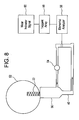
- FIGURE 8 is a schematic block diagram of system for collecting and detecting
-
- The term "luminescence" means a light emission that cannot be attributed merely to the temperature of an emitting body, but results from such causes as chemical reactions at ordinary temperatures, electron bombardment, electromagnetic radiation or electric fields. A "phosphor" is a substance that converts part of an absorbed primary energy into emitted luminescent radiation. In this application, the term "indicator" includes a phosphor compound that exhibits fluorescence and non-luminescent materials that can be detected in a gas stream after release from a binder.
- The invention provides a particular binder and indicator combination monitoring deposit to a part that permits indicator release within a critical temperature range that is high enough to assure efficient turbine engine operation while avoiding excessively high temperatures that will deteriorate engine parts. The binder/indicator deposit comprises a binder that melts within the critical temperature range to release the indicator for detection.
- An embodiment of the invention relates to an "on-line" assessment method in which a gas turbine part is tagged with a monitoring deposit that includes a selected customized binder containing a specific indicator. The binder is selected according to a critical temperature of the part on which the binder/indicator composition is applied. The indicator is selected to specifically and uniquely identify its applied part as a source part to a down stream detector. At the critical temperature, the binder melts to release the unique indicator. When detected downstream, the indicator identifies the source part and its degree of deterioration. This information provides improved "on-line" knowledge of a coated part's condition and determines a replacement and repair strategy to improve machine operational up-time. "Online" means that the assessment is determined without interrupting the operation of the turbine. A preferred embodiment of invention includes smart binder/indicator compositions that serve as online indicators of the degree of wear and damage of gas turbine section parts.
- Features of the invention will become apparent from the drawings and following detailed discussion, which by way of example without limitation describe preferred embodiments of the invention.
- FIGURES 1 to 4 of the figures are schematic representations of indicator and binder combination monitoring deposits applied onto a substrate and FIG. 5 is a schematic representation of an indicator releasing from the binder of a combination monitoring deposit. In these figures, binder/
indicator composition 10 includesindicator 12 combined intobinder 14 and applied ontosubstrate 16. - The binder/indicator composition of the invention can be formed and applied to a substrate in a variety of ways. FIGURE 1 shows a
composition 10 in the form ofindicator 12 particles that have been pre-coated withbinder 14 and then applied to anupper surface 18 of thesubstrate 16. FIGURE 2 shows acomposition 10 that has been formed by first applyingindicator 12 particles to anupper surface 18 of thesubstrate 16 followed by application ofbinder 14 to encompass theindicator 12 particles. In FIGURE 3, a well 20 is first formed into thesubstrate 16.Indicator 12 particles are deposited into the well 20, which is subsequently capped by thebinder 14. -
Indicator 12 can be either a chemical compound or element. As shown, theindicator 12 is doped into thebinder 14 or applied to asubstrate 16 and covered by thebinder 14. The indicator is detected upon release from thebinder 14 when the binder begins to melt when a critical operating temperature is reached. The indicator is identified to indicate that a particular part has reached the critical temperature. In a preferred embodiment, hereinafter described in detail, different binder/indicator compositions are applied to different sets of parts of a gas turbine. Released indicators are in an exhaust stream, indicating wear or damage to particular turbine parts. - The indicator is selected to be stable and relatively inactive with respect to diffusion at the high turbine operating temperatures involved, and to not have a deleterious effect on coating and turbine performance. The indicator is selected to retain fluorescence upon exposure to high temperatures for extended periods. The indicator will not react with or dissolve in the binder material. It is easily detected by a fluorescent particle sampling technique. Preferably, the indicator is reliably detectable in small concentrations. Suitable fluorescent indicators are available commercially. For example, a variety of inorganic fluorescent indicators catalogue # SFP-0010, (white), #SFP-0013 (green) and SFP-0018 (red) are available from Spectra Systems Corporation, 321 South Main Street, Providence, RI 02903.
- A variety of binders is suitable in the invention. The binder must not chemically react or corrode the substrate material. The binder must not degrade physically during operation. The binder must melt at a characteristic temperature that is of interest and in the process, release the fluorescent particles into the turbine exhaust. The binder must be non-hazardous and non-toxic. The binder must not be prohibitively expensive. The binder must not react with, dissolve or degrade the fluorescent particles.
- TABLE 1 provides a list of binders and their associated melting points.
Binder m.p. °C m.p. °F Binder m.p. °C m.p. °F Binder m.p. °C m.p. °F CeCl3 848 1558.4 K2Ca(SO4)2 1004 1839.2 PbSO4 1114 2037.2 BaBr2 880 1616 Yl3 1004 1839.2 CdTe 1121 2049.8 K2CO3 891 1635.8 Cs2SO4 1010 1850 KAlSi3O8 1140 2084 LuCl3 905 1661 Pb2(PO4)2 1014 1857.2 HoF3 1143 2089.4 La 918 1684.4 Erl3 1020 1868 FeSiO3 1146 2094.8 Gdl3 926 1698.8 Ac 1050 1922 CrCl3 1150 2102 Li2S 950 1742 In2S3 1050 1922 PbSO4 1170 2138 KBO2 950 1742 Lul3 1050 1922 FeS2 1171 2139.8 Dyl3 955 1751 PbMoO4 1060 1940 LuF3 1182 2159.6 GaS 965 1769 Sm 1074 1965.2 Mg3(PO4)2 1184 2163.2 Ce2(MO4)3 973 1783.4 Cu 1083 1981.4 FeS 1193 2179.4 Ca(PO3)2 975 1787 CuSCN 1084 1983.2 Ca3N2 1195 2183 K2SiO3 976 1788.8 GeO2 1086 1986.8 BaS 1200 2192 Hol3 989 1812.2 Mn3P2 1095 2003 Cu2O 1235 2255 NaF 993 1819.4 Al2S3 1100 2012 CaOFe2O3 1250 2282 Am 994 1821.2 CrF2 1100 2012 CdSO4 1000 1832 Fe3P 1100 2012 Na2OAl2O34SiO3 1000 1832 Mg2Si 1102 2015.6 - A eutectic binder mixture can be used as the binder in another embodiment of the invention. For example, the eutectic LiCl with 40 mol% KCI melts at 350 °C. A LiCl/NaCl mixture melts between 552 °C and 819 °C, depending on the ratio of the two components. A eutectic permits a combination to be customized for application to numerous parts sections wherein each is sensitive to a different temperature effect. An additional advantage of the eutectic binder is that variables related to chemical reactivity, physical erosion, corrosion etc., are roughly equivalent while the characteristic melting point can be varied for use in connection with a variety of turbine engine parts.
- As FIGURES. 1 to 4 illustrate, the binder/
indicator composition 10 can be applied in a number of different ways. In some cases, the binder and indicator can be blended together, then melted and applied as spots at various locations on an airfoil. In another embodiment, a small well is drilled into the surface of the airfoil, the well filled with an indicator such as fluorescent particles and a molten binder is applied to seal the well at the airfoil surface. Combinations of these techniques can be used. - Suitable indicator materials include yttrium oxide doped with +3 europium, Ce1XYLaXTbYMgAl11O19, where O<X<0.2 and 0.2<Y<0.4, cerium magnesium aluminate doped with +3 terbium, or yttrium oxide doped with +3 europium, especially Ce0.7Tb0.3MgAl11O19 (CAT) and the like. Additional phosphors that can be used as indicators include Zn2SiO4 doped with Mn or As, La2O2S doped with Tb, Y2O2S doped with Eu, CaWO4, and Gd2O2S doped with Tb, LaPO4 doped with Ce and Tb, LaPO4 with Eu. In addition to the luminescent indicators, indicators may be selected from radioactive isotopes or certain metal indicators such as Cr or Co.
- Some exemplary binder/indicator combinations include the binders of TABLE 1 and inorganic fluorescent indicators. Preferred binders include Na2O·Al2O34·SiO3, K2SiO3 and K2Ca(SO4)2 in combination with organometallic indicators such as SFP-0010 (white) and SFP-0013 (green) and SFP-0018 (red) available from Spectra Systems Corporation, 321 South Main Street, Providence, RI 02903. A europium chelate indicator such as SFP-0008 (red) is a preferred indicator. The indicator can be present in the binder/indicator combination in any proportion so long as integrity of the composition is maintained until a critical temperature is reached at which the binder melts to release the indicator. Broadly, the indicator can be present in percent by weight of the composition in a range of 1% to 99%, desirably 25% to 95% and preferably 80% to 90%.
- The indicator and binder combination can be applied to any substrate in need of temperature monitoring in a deleterious operating environment. Preferably, the substrate is a part of a gas turbine that is prone to wear or damage. The turbine parts include combustors, transition pieces and high pressure turbine airfoils. The substrate can be another turbine engine part as well, such as a first stage high pressure turbine blade. Coatings of the preferred embodiments of the invention may be applied to the entire surface of these parts, or alternatively, to a portion of these parts. Preferably, the indicators are doped into layers or interfaces of coatings that are present in turbine parts that are subject to wear and damage, erosion, oxidation, and corrosion. A preferred substrate is a coating for insulating a gas turbine part. One such coating is a ceramic insulating layer, referred to as a thermal barrier coating (TBC). The heat-diffusible indicator can be applied to any substrate subject to exposure to a deleterious thermal environment. Metal substrates, such as steel, for example valve seats, turbine buckets, turbine blades, vanes, combustor liners, transition pieces, nozzles, reaction vessels, pressure vessels, boilers and various other surfaces are among the substrates that can be monitored in accordance with the invention for differential erosion or corrosion. Suitable ceramic substrates include alumina shafts that are subject to differential wear or differential erosion or corrosion.
- An embodiment of the invention relates to a system for monitoring a gas turbine engine. The embodiment permits assessing conditions of the gas turbine coatings and substrates on-line. FIGURE 6 is a perspective view of a turbine
engine collection device 20 for collecting indicators from an exhaust stream of a turbine engine and FIGURE 7 is a schematic cross-sectional view of thedevice 20 of FIGURE 6. These figures depict asingle tube 22 that has multiple open ends 24 that face directly into the exhaust gas stream indicated generally by 26. Thetube 22 collects a small percentage sample of theexhaust stream 26 and delivers its exhaust sample viaduct 28 to aseparator 30 such as a cyclone separator. Theseparator 30 concentrates the particulate matter while the sampledexhaust stream 26 cools. The concentrated output ofseparator 30 is directed to a water-gas separator 32 that comprises a cone-shaped surface 34 (shown in FIGURE 7). A stream ofwater 36 passing from a rinsewater inlet 38 flows over thesurface 34 to capture the concentrated particles. The stream ofwater 36 then flows downwater outlet 40 shown at the bottom of FIGURE 7. Thermocouple 42 measures the temperature of theexhaust gas stream 26. A manifold 44 can be provided to distributewater stream 36 completely around the cone-shapedsurface 34 circumference. Theexhaust stream 26 exits separator 30 viaprimary exhaust return 46 orsecondary exhaust return 48. The water stream is filtered by a particle filter 50 to recover a particulate indicator-containing fraction and thestream 36 is circulated toinlet 38. - Again with reference to FIGURE 7, particles separated from the exhaust stream by the
separator 32 are carried by exhaust gas to acompartment 62, which is lined withcompartment filter 64 and is connected to theseparator 32 for periodic retrieval and analysis. For example, closingvalve 66 andopening valve 68 causes indicator-containing particles to be deposited incompartment 62 by way of deposition oncompartment filter 64. - The
collection device 20 is depicted byicon 20 in FIGURE 8. As discussed generally with reference to FIGURES. 6 and 7 and more specifically herein with reference to FIGURE 8,tubes 22 face directly into anexhaust gas stream 26 of turbine 50. Thetubes 22 are in fluid communication withseparator 30. Rinse water containing exhaust particles leaves theseparator 30 atoutlet 40 and proceeds to particle filter 50.Pump 54 continually forces rinse water back toseparator inlet 38. The filter 50 is removed and the filtered particles are subjected to elemental analysis byanalyzer 56 to assay for the presence of anindicator array 58. The individual indicators ofarray 58 are determined. A positive indication of the presence of an indicator associated with a particular turbine part generates awear indicator signal 60 for that part.Analysis 56 of the particulate indicator-containing fraction can be accomplished by a number of methods including plasma flame spectrometry and mass spectrometry. - The following Examples are illustrative and should not be construed as a limitation on the scope of the claims unless a limitation is specifically recited.
- A pattern of 0.3 mm X 0.3 mm cylindrical holes, regularly spaced at 1 cm intervals to form a grid, is drilled with a laser into a MCrAIY coating on an airfoil surface. A slurry of SFP-0010, white fluorescent particle material is prepared in distilled water. The slurry is introduced into the holes by means of a syringe. The water is evaporated by gentle heating. Na2O·Al2O34·SiO3 (100 g, m.p. 1000 °C) binder is placed in a syringe and is melted by a hot glue gun. The melted binder is introduced as small droplet particles into the holes. Excess binder material is removed by attrition with fine emory paper so that the wells are flush with the airfoil surface.
- The airfoil is then re-introduced into service. When a surface temperature of the airfoil reaches the melting point of the binder (1832 F), the binder melts, releasing the fluorescent particle material an exhaust stream. The material is captured by the device illustrated in FIGURES 6 and 7. The material is detected and identified by plasma flame spectrometry to indicate that the location of the pattern is subjected to a local temperature of at least 1000 °C.
- For the sake of good order, various aspects of the invention are set out in the following clauses:-
- 1. A method for forming a monitoring deposit on a substrate (16),
comprising:
- determining a temperature range to subject the substrate (16) to provide a high temperature of operation up to less than a critical substrate deterioration temperature;
- selecting a binder (14) to monitor temperature by emitting an indicator within the determined temperature range;
- combining the indicator and the binder (14); and
- applying the combined indicator and binder (14) to the substrate (16) to form the monitoring deposit.
- 2. The method of clause 1, additionally comprising collecting the indicator from an exhaust gas stream which passed over the substrate (16) to provide a particulate containing fraction.
- 3. The method of clause 1, additionally comprising collecting the indicator from an exhaust gas stream which passed over the substrate (16) to provide a particulate containing fraction.
- 4. The method of clause 1, additionally comprising collecting the indicator from an exhaust gas stream which passed over the substrate (16) to provide a particulate containing fraction and analyzing the particulate containing fraction for the indicator.
- 5. The method of clause 1, additionally comprising collecting the indicator from an exhaust gas stream which passed over the substrate (16) to provide a particulate containing fraction and analyzing the particulate containing fraction for the indicator to determine wear or damage to the part.
- 6. The method of clause 1, additionally comprising collecting the indicator from an exhaust gas stream which passed over the substrate (16) to provide a particulate containing fraction; concentrating particles in the particulate containing fraction; and analyzing the particulate containing fraction.
- 7. The method of clause 1, additionally comprising collecting the indicator from an exhaust gas stream which passed over the part to provide a particulate containing fraction; concentrating particles in the particulate containing fraction; and analyzing the particulate containing fraction for the indicator to determine wear or damage to the part.
- 8. The method of clause 1, comprising selecting a eutectic composition as the binder (14).
- 9. The method of clause 1, comprising forming a pattern of wells in a surface (18) of the substrate (16), placing indicator into the wells and sealing the well with binder (14) to form the monitoring deposit.
- 10. The method of clause 1, comprising applying the combined indicator and binder (14) at a first selected location on the substrate (16) to form a monitoring deposit at a first location and applying a different binder or different indicator at a second selected location to form a separate monitoring deposit on the substrate (16) to permit simultaneous monitoring of both the first location and second location.
- 11. An article, comprising:
- a substrate (16); and
- a combined indicator and binder (14) applied into the substrate (16), wherein the binder (14) emits the indicator within a temperature range determined to subject the substrate (16) to high temperature operation up to less than a critical substrate deterioration temperature
- 12. The article of clause 11, wherein the indicator is a phosphor.
- 13. The article of clause 11, wherein the indicator is a eutectic mixture.
- 14. The article of clause 11, wherein the binder (14) is a eutectic mixture of LiCl with KCl.
- 15. The article of clause 11, wherein the binder (14) is a eutectic mixture of LiCI with NaCI.
- 16. The article of clause 11, wherein the binder (14) is a eutectic mixture of components in a proportion selected to provide release of indicator within the determined temperature range.
- 17. The article of clause 11, wherein the binder (14) is K2SiO3, Na2O·Al2O34·SiO3, K2SiO3 or K2Ca(SO4)2 and the indicator is an europium chelate.
- 18. The article of clause 11, wherein the indicator is present in the combined indicator and binder (14) in a percent by weight from 1% to 99%.
- 19. The article of clause 11, wherein the indicator is present in the combined indicator and binder (14) in a percent by weight from 25% to 95%.
- 20. The article of clause 11, wherein the indicator is present in the combined indicator and binder (14) in a percent by weight from 80% to 90%,
- 21. A method of monitoring a gas turbine system, comprising:
- selecting a binder (14) to monitor temperature by emitting an indicator within a temperature range determined to permit subjecting a substrate (16) in the system to high temperature operation up to less than a critical turbine substrate deterioration temperature
- combining the indicator and the binder (14); and
- applying the combined indicator and binder (14) to the substrate (16) to form the monitoring deposit.
- 22. The method of clause 21, wherein the binder (14) releases the indicator into an exhaust gas stream, when the system operating temperature reaches a melting point of the binder (14).
- 23. The method of clause 21, additionally comprising collecting the indicator from an exhaust gas stream which passed over the turbine substrate part to provide a particulate containing fraction.
- 24. The method of clause 21, additionally comprising collecting the indicator from an exhaust gas stream which passed over the turbine substrate part to provide a particulate containing fraction.
- 25. The method of clause 21, additionally comprising collecting the indicator from an exhaust gas stream which passed over the turbine substrate part to provide a particulate containing fraction and analyzing the particulate containing fraction for the indicator.
- 26. The method of clause 21, additionally comprising collecting the indicator from an exhaust gas stream which passed over the turbine substrate part to provide a particulate containing fraction and analyzing the particulate containing fraction for the indicator to determine wear or damage to the gas turbine part.
- 27. The method of clause 21, additionally comprising collecting the indicator from an exhaust gas stream which passed over the turbine substrate part to provide a particulate containing fraction; concentrating particles in the particulate containing fraction; and analyzing the particulate containing fraction.
- 28. The method of clause 21, additionally comprising collecting the indicator from an exhaust gas stream which passed over the turbine substrate part to provide a particulate containing fraction; concentrating particles in the particulate containing fraction; and analyzing the particulate containing fraction for the indicator to determine wear or damage to the gas turbine part.
- 29. The method of clause 21, wherein the substrate (16) is a gas turbine part selected from a combustor, transition piece and airfoil.
- 30. The method of clause 21, wherein the substrate (16) comprises a thermal barrier coating (TBC).
- 31. The method of clause 21, comprising selecting a eutectic composition as the binder (14).
- 32. The method of clause 21, comprising applying a plurality of combined indicators and binders (14) to a plurality of part substrates.
- 33. The method of clause 21, comprising selecting a plurality of binders (14) for application to a plurality of part substrates, each binder (14) selected according to a temperature range determined to permit subjecting the respective part substrate on which the binder (14) is applied to a high temperature operation up to less than a critical substrate deterioration temperature for the respective part substrate.
- 34. The method of clause 21, additionally comprising selecting a plurality of indicators for application to a plurality of part substrates, each indicator selected to be different from each other indicator.
- 35. The method of clause 21, comprising selecting a eutectic composition as the binder (14).
- 36. The method of clause 21, comprising forming a pattern of wells in a surface (18) of the substrate (16), placing indicator into the wells and sealing the well with binder (14) to form the monitoring deposit.
- 37. The method of clause 21, comprising applying the combined indicator and binder (14) at a first selected location on the substrate (16) to form a monitoring deposit at a first location and applying a different binder (14) or different indicator at a second selected location to form a separate monitoring deposit on the substrate (16) to permit simultaneous monitoring of both the first location and second location.
- 38. A system for monitoring a gas turbine engine, comprising:
- a substrate (16); and
- a combined indicator and binder (14) applied onto the substrate (16), wherein the binder (14) emits the indicator within a temperature range determined to permit subjecting the substrate (16) to high temperature operation up to less than a critical substrate deterioration temperature.
- 39. The system of
clause 38 including a sensor to sense the indicator when released from the binder (14). - 40. The system of
clause 38, further comprising a exhaust gas collector in fluid communication with the turbine substrate (16), whereby the collector samples a portion of an exhaust gas that passes over the substrate (16). - 41. The system of
clause 38, further comprising a exhaust gas collector in fluid communication with the turbine substrate (16), whereby the collector samples a portion of an exhaust gas that passes over the substrate (16) and
an exhaust particle seperator (30) connected to the gas exhaust collector, whereby the seperator (30) separates particles from the exhaust gas. - 42. The system of
clause 38, further comprising a exhaust gas collector in fluid communication with the turbine substrate (16), whereby the collector samples a portion of an exhaust gas that passes over the substrate (16) and
an exhaust particle seperator (30) connected to the gas exhaust collector, whereby the seperator (30) separates particles from the exhaust gas and further comprising an analyzer connected to the seperator (30), wherein the analyzer is capable of detecting the indicator. -
Claims (10)
- A method of monitoring a gas turbine system, comprising:selecting a binder (14) to monitor temperature by emitting an indicator within a temperature range determined to permit subjecting a substrate (16) in the system to high temperature operation up to less than a critical turbine substrate deterioration temperaturecombining the indicator and the binder (14); andapplying the combined indicator and binder (14) to the substrate (16) to form the monitoring deposit.
- The method of claim 1, wherein the binder (14) releases the indicator into an exhaust gas stream, when the system operating temperature reaches a melting point of the binder (14).
- The method of claim 1 or 2, additionally comprising collecting the indicator from an exhaust gas stream which passed over the turbine substrate part to provide a particulate containing fraction.
- The method of claim 3, additionally comprising analyzing the particulate containing fraction for the indicator.
- The method of claim 4, wherein the particulate containing fraction is analysed to determine wear or damage to the gas turbine part.
- A system for monitoring a gas turbine engine, comprising:a substrate (16); anda combined indicator and binder (14) applied onto the substrate (16), wherein the binder (14) emits the indicator within a temperature range determined to permit subjecting the substrate (16) to high temperature operation up to less than a critical substrate deterioration temperature.
- The system of claim 6 including a sensor to sense the indicator when released from the binder (14).
- The system of claim 6 or 7, further comprising a exhaust gas collector in fluid communication with the turbine substrate (16), whereby the collector samples a portion of an exhaust gas that passes over the substrate (16).
- The system of claim 8, wherein the collector samples a portion of an exhaust gas that passes over the substrate (16) and wherein an exhaust particle separator (30) is connected to the gas exhaust collector, whereby the separator (30) separates particles from the exhaust gas.
- The system of claim 9, further comprising a exhaust gas collector in fluid communication with the turbine substrate (16), whereby the collector samples a portion of an exhaust gas that passes over the substrate (16) and
an exhaust particle separator (30) connected to the gas exhaust collector, whereby the separator (30) separates particles from the exhaust gas and further comprising an analyzer connected to the separator (30), wherein the analyzer is capable of detecting the indicator.
Applications Claiming Priority (2)
| Application Number | Priority Date | Filing Date | Title |
|---|---|---|---|
| US294727 | 1989-01-06 | ||
| US10/294,727 US7052737B2 (en) | 2002-11-15 | 2002-11-15 | Forming a monitoring deposit on a substrate |
Publications (2)
| Publication Number | Publication Date |
|---|---|
| EP1420234A1 true EP1420234A1 (en) | 2004-05-19 |
| EP1420234B1 EP1420234B1 (en) | 2015-09-02 |
Family
ID=32176193
Family Applications (1)
| Application Number | Title | Priority Date | Filing Date |
|---|---|---|---|
| EP03257148.1A Expired - Lifetime EP1420234B1 (en) | 2002-11-15 | 2003-11-12 | Method for selecting a binder for a thermal indicator in a gas turbine system |
Country Status (5)
| Country | Link |
|---|---|
| US (1) | US7052737B2 (en) |
| EP (1) | EP1420234B1 (en) |
| JP (1) | JP4439243B2 (en) |
| KR (1) | KR100825142B1 (en) |
| CN (1) | CN1510415B (en) |
Cited By (3)
| Publication number | Priority date | Publication date | Assignee | Title |
|---|---|---|---|---|
| EP1724026A1 (en) * | 2005-05-20 | 2006-11-22 | General Electric Company | Temperature dependent transparent optical coatings for high temperature absorption |
| EP1724027A1 (en) * | 2005-05-20 | 2006-11-22 | General Electric Company | Temperature dependent transparent optical coatings for high temperature reflection |
| US9791351B2 (en) | 2015-02-06 | 2017-10-17 | General Electric Company | Gas turbine combustion profile monitoring |
Families Citing this family (20)
| Publication number | Priority date | Publication date | Assignee | Title |
|---|---|---|---|---|
| US7270890B2 (en) * | 2002-09-23 | 2007-09-18 | Siemens Power Generation, Inc. | Wear monitoring system with embedded conductors |
| DE202004007476U1 (en) * | 2004-03-26 | 2004-09-02 | Stabila-Meßgeräte Gustav Ullrich GmbH | Alignment device for formation of linear optical markings, e.g. a laser-level instrument, whereby markings are formed with grooved shaped lenses that cause light to reflect in different directions dependent on its incident position |
| US7123031B2 (en) * | 2004-12-20 | 2006-10-17 | Siemens Power Generation, Inc. | System for on-line assessment of the condition of thermal coating on a turbine vane |
| US8247018B2 (en) * | 2005-06-20 | 2012-08-21 | Authentiform Technologies, Llc | Methods for quality control |
| US8458475B2 (en) * | 2005-06-20 | 2013-06-04 | Authentiform Technologies, L.L.C. | Systems and methods for product authentication |
| US7874489B2 (en) * | 2005-06-20 | 2011-01-25 | Authentiform Technologies, Llc | Product authentication |
| US7632012B2 (en) * | 2005-09-01 | 2009-12-15 | Siemens Energy, Inc. | Method of measuring in situ differential emissivity and temperature |
| EP2265677B1 (en) * | 2008-04-09 | 2019-05-15 | Battelle Memorial Institute | Corrosion detection product and method |
| US8490474B2 (en) * | 2010-12-30 | 2013-07-23 | General Electric Company | Methods, systems and apparatus for detecting material defects in combustors of combustion turbine engines |
| US20120169326A1 (en) * | 2010-12-30 | 2012-07-05 | General Electric Company | Methods, systems and apparatus for detecting material defects in combustors of combustion turbine engines |
| US8158428B1 (en) * | 2010-12-30 | 2012-04-17 | General Electric Company | Methods, systems and apparatus for detecting material defects in combustors of combustion turbine engines |
| EP2915098A4 (en) | 2012-10-30 | 2016-07-06 | Certirx Corp | Product, image, or document authentication, verification, and item identification |
| EP2943714A4 (en) * | 2013-01-09 | 2016-08-17 | Cidra Corporate Services Inc | INTELLIGENT PIPE CONCEPT USING A MARKER SENSOR AND / OR COLORED-COLOR CODE ELEMENTS TO MONITOR THE WEAR OF A COATING IN COATED PIPES, ESPECIALLY IN A URETHANE-COATED PIPE |
| US20150125681A1 (en) * | 2013-11-06 | 2015-05-07 | United Technologies Corporation | High Temperature Imaging Media for Digital Image Correlation |
| US9804058B2 (en) | 2014-02-27 | 2017-10-31 | Pratt & Whitney Canada Corp. | Method of facilitating visual detection of a crack in a component of a gas turbine engine |
| US9790834B2 (en) | 2014-03-20 | 2017-10-17 | General Electric Company | Method of monitoring for combustion anomalies in a gas turbomachine and a gas turbomachine including a combustion anomaly detection system |
| JP2016138672A (en) * | 2015-01-26 | 2016-08-04 | 住友重機械工業株式会社 | Fluidized bed reactor |
| US9453727B1 (en) | 2015-08-03 | 2016-09-27 | Siemens Energy, Inc. | Nondestructive detection of dimensional changes in a substrate using subsurface markers |
| WO2022026115A1 (en) * | 2020-07-03 | 2022-02-03 | Raytheon Technologies Corporation | Dislocator chemistries for turbine abradable or machinable coating systems |
| CN119978878B (en) * | 2025-01-06 | 2025-11-18 | 北京航空航天大学 | Phosphorescent temperature-measuring coating and preparation method thereof |
Citations (5)
| Publication number | Priority date | Publication date | Assignee | Title |
|---|---|---|---|---|
| US4272988A (en) * | 1975-04-15 | 1981-06-16 | Westinghouse Electric Corp. | Multiple signal thermoparticulating coating |
| US4327155A (en) * | 1980-12-29 | 1982-04-27 | General Electric Company | Coated metal structures and method for making |
| US4327120A (en) * | 1981-01-28 | 1982-04-27 | General Electric Company | Method for coating a metal substrate |
| DE3638265C1 (en) * | 1986-11-10 | 1988-03-03 | Mtu Muenchen Gmbh | Temperature/time indicator |
| US6200088B1 (en) * | 1998-08-06 | 2001-03-13 | Siemens Westinghouse Power Corporation | On-line monitor for detecting excessive temperatures of critical components of a turbine |
Family Cites Families (7)
| Publication number | Priority date | Publication date | Assignee | Title |
|---|---|---|---|---|
| CA1163872A (en) * | 1982-01-21 | 1984-03-20 | Rodney E. Hanneman | Coated metal structures and method for making |
| DE3737502A1 (en) * | 1986-11-10 | 1988-05-19 | Mtu Muenchen Gmbh | Temperature indicator |
| DE3638266A1 (en) * | 1986-11-10 | 1988-05-19 | Mtu Muenchen Gmbh | Temperature indicator |
| US5578828A (en) * | 1994-11-15 | 1996-11-26 | General Electric Company | Flame sensor window coating compensation |
| US5865598C1 (en) * | 1997-07-02 | 2001-01-02 | Siemens Westinghouse Power | Hot spot detection system for vanes or blades of a combustion turbine |
| EP1105550B1 (en) | 1998-07-27 | 2003-03-12 | Imperial College Of Science, Technology & Medicine | Thermal barrier coating with thermoluminescent indicator material embedded therein |
| US6644917B2 (en) * | 2001-08-14 | 2003-11-11 | General Electric Company | Smart coating system with chemical taggants for coating condition assessment |
-
2002
- 2002-11-15 US US10/294,727 patent/US7052737B2/en not_active Expired - Lifetime
-
2003
- 2003-11-12 EP EP03257148.1A patent/EP1420234B1/en not_active Expired - Lifetime
- 2003-11-14 JP JP2003385258A patent/JP4439243B2/en not_active Expired - Fee Related
- 2003-11-14 KR KR1020030080532A patent/KR100825142B1/en not_active Expired - Fee Related
- 2003-11-15 CN CN2003101198488A patent/CN1510415B/en not_active Expired - Fee Related
Patent Citations (5)
| Publication number | Priority date | Publication date | Assignee | Title |
|---|---|---|---|---|
| US4272988A (en) * | 1975-04-15 | 1981-06-16 | Westinghouse Electric Corp. | Multiple signal thermoparticulating coating |
| US4327155A (en) * | 1980-12-29 | 1982-04-27 | General Electric Company | Coated metal structures and method for making |
| US4327120A (en) * | 1981-01-28 | 1982-04-27 | General Electric Company | Method for coating a metal substrate |
| DE3638265C1 (en) * | 1986-11-10 | 1988-03-03 | Mtu Muenchen Gmbh | Temperature/time indicator |
| US6200088B1 (en) * | 1998-08-06 | 2001-03-13 | Siemens Westinghouse Power Corporation | On-line monitor for detecting excessive temperatures of critical components of a turbine |
Cited By (3)
| Publication number | Priority date | Publication date | Assignee | Title |
|---|---|---|---|---|
| EP1724026A1 (en) * | 2005-05-20 | 2006-11-22 | General Electric Company | Temperature dependent transparent optical coatings for high temperature absorption |
| EP1724027A1 (en) * | 2005-05-20 | 2006-11-22 | General Electric Company | Temperature dependent transparent optical coatings for high temperature reflection |
| US9791351B2 (en) | 2015-02-06 | 2017-10-17 | General Electric Company | Gas turbine combustion profile monitoring |
Also Published As
| Publication number | Publication date |
|---|---|
| US7052737B2 (en) | 2006-05-30 |
| JP2004169698A (en) | 2004-06-17 |
| JP4439243B2 (en) | 2010-03-24 |
| CN1510415B (en) | 2010-04-28 |
| KR100825142B1 (en) | 2008-04-24 |
| US20040096314A1 (en) | 2004-05-20 |
| EP1420234B1 (en) | 2015-09-02 |
| CN1510415A (en) | 2004-07-07 |
| KR20040042895A (en) | 2004-05-20 |
Similar Documents
| Publication | Publication Date | Title |
|---|---|---|
| US7052737B2 (en) | Forming a monitoring deposit on a substrate | |
| CA2950548C (en) | Coating inspection method | |
| US7858952B2 (en) | Coatings and a method of optically detecting corrosion in coatings | |
| US6943357B2 (en) | Thermal barrier coatings, components, method and apparatus for determining past-service conditions and remaining life thereof | |
| Wenglarz et al. | Chemical aspects of deposition/corrosion from coal-water fuels under gas turbine conditions | |
| US6644917B2 (en) | Smart coating system with chemical taggants for coating condition assessment | |
| CN101205833A (en) | Thermal barrier coating | |
| JP2002511943A (en) | Detecting device for hot spot of stationary or moving blade of combustion turbine | |
| EP2452178A1 (en) | Luminescent wear sensing | |
| Horner et al. | Development of a water-cooled gas turbine | |
| Pilgrim et al. | Thermal barrier sensor coatings-sensing damage and ageing in critical components | |
| JP4986730B2 (en) | Judgment method for coating deterioration of high temperature metal products | |
| US20120190118A1 (en) | Component having a protective layer that can be monitored magnetically and method for operating a component | |
| Nakamori et al. | Hot corrosion and its prevention in high temperature heavy oil firing gas turbines | |
| Cheruvu et al. | In-service degradation and life prediction of coatings for advanced land-based gas turbine buckets | |
| Wada et al. | Degradation of gas turbine blade materials in integrated coal-gasification combined cycle plant | |
| Horner et al. | Water-Cooled Gas Turbine Technology Development: Fuels Flexibility | |
| Diamantino et al. | NEWS4CSP Project–New Coatings Approaches to Protect Metallic Materials From Heat Transfer Fluids | |
| Allison et al. | Phosphor Thermometry of Gas Turbine Surfaces | |
| Birks et al. | Study of the Erosion Corrosion of Alloys and Coatings. | |
| Srivastava et al. | Method And Apparatus For Determining Health Of Thermal Barrier Coatings | |
| Blanton et al. | Heavy fuels ash deposit formation and removal in water-cooled high temperature gas turbines | |
| Sumner et al. | Lifetime prediction for gas turbine materials in power generation | |
| Minchener et al. | IEA Grimethorpe 2× 2M PFBC Facility: Turbine Materials Testing in a Cascade Loop | |
| Tiwari et al. | Fireside Corrosion in Boilers |
Legal Events
| Date | Code | Title | Description |
|---|---|---|---|
| PUAI | Public reference made under article 153(3) epc to a published international application that has entered the european phase |
Free format text: ORIGINAL CODE: 0009012 |
|
| AK | Designated contracting states |
Kind code of ref document: A1 Designated state(s): AT BE BG CH CY CZ DE DK EE ES FI FR GB GR HU IE IT LI LU MC NL PT RO SE SI SK TR |
|
| AX | Request for extension of the european patent |
Extension state: AL LT LV MK |
|
| 17P | Request for examination filed |
Effective date: 20041119 |
|
| AKX | Designation fees paid |
Designated state(s): CH DE FR GB IT LI |
|
| 17Q | First examination report despatched |
Effective date: 20100908 |
|
| GRAP | Despatch of communication of intention to grant a patent |
Free format text: ORIGINAL CODE: EPIDOSNIGR1 |
|
| INTG | Intention to grant announced |
Effective date: 20150407 |
|
| GRAS | Grant fee paid |
Free format text: ORIGINAL CODE: EPIDOSNIGR3 |
|
| GRAA | (expected) grant |
Free format text: ORIGINAL CODE: 0009210 |
|
| AK | Designated contracting states |
Kind code of ref document: B1 Designated state(s): CH DE FR GB IT LI |
|
| REG | Reference to a national code |
Ref country code: GB Ref legal event code: FG4D |
|
| REG | Reference to a national code |
Ref country code: CH Ref legal event code: EP |
|
| REG | Reference to a national code |
Ref country code: DE Ref legal event code: R096 Ref document number: 60347985 Country of ref document: DE |
|
| REG | Reference to a national code |
Ref country code: FR Ref legal event code: PLFP Year of fee payment: 13 |
|
| REG | Reference to a national code |
Ref country code: DE Ref legal event code: R097 Ref document number: 60347985 Country of ref document: DE |
|
| PLBE | No opposition filed within time limit |
Free format text: ORIGINAL CODE: 0009261 |
|
| STAA | Information on the status of an ep patent application or granted ep patent |
Free format text: STATUS: NO OPPOSITION FILED WITHIN TIME LIMIT |
|
| 26N | No opposition filed |
Effective date: 20160603 |
|
| REG | Reference to a national code |
Ref country code: FR Ref legal event code: PLFP Year of fee payment: 14 |
|
| REG | Reference to a national code |
Ref country code: FR Ref legal event code: PLFP Year of fee payment: 15 |
|
| REG | Reference to a national code |
Ref country code: FR Ref legal event code: PLFP Year of fee payment: 16 |
|
| PGFP | Annual fee paid to national office [announced via postgrant information from national office to epo] |
Ref country code: DE Payment date: 20181023 Year of fee payment: 16 |
|
| PGFP | Annual fee paid to national office [announced via postgrant information from national office to epo] |
Ref country code: IT Payment date: 20181023 Year of fee payment: 16 Ref country code: CH Payment date: 20181030 Year of fee payment: 16 Ref country code: FR Payment date: 20181024 Year of fee payment: 16 Ref country code: GB Payment date: 20181024 Year of fee payment: 16 |
|
| REG | Reference to a national code |
Ref country code: DE Ref legal event code: R119 Ref document number: 60347985 Country of ref document: DE |
|
| REG | Reference to a national code |
Ref country code: CH Ref legal event code: PL |
|
| PG25 | Lapsed in a contracting state [announced via postgrant information from national office to epo] |
Ref country code: LI Free format text: LAPSE BECAUSE OF NON-PAYMENT OF DUE FEES Effective date: 20191130 Ref country code: CH Free format text: LAPSE BECAUSE OF NON-PAYMENT OF DUE FEES Effective date: 20191130 |
|
| GBPC | Gb: european patent ceased through non-payment of renewal fee |
Effective date: 20191112 |
|
| PG25 | Lapsed in a contracting state [announced via postgrant information from national office to epo] |
Ref country code: FR Free format text: LAPSE BECAUSE OF NON-PAYMENT OF DUE FEES Effective date: 20191130 Ref country code: GB Free format text: LAPSE BECAUSE OF NON-PAYMENT OF DUE FEES Effective date: 20191112 Ref country code: IT Free format text: LAPSE BECAUSE OF NON-PAYMENT OF DUE FEES Effective date: 20191112 Ref country code: DE Free format text: LAPSE BECAUSE OF NON-PAYMENT OF DUE FEES Effective date: 20200603 |