EP1420218A2 - Heat-save cooler - Google Patents
Heat-save cooler Download PDFInfo
- Publication number
- EP1420218A2 EP1420218A2 EP03025862A EP03025862A EP1420218A2 EP 1420218 A2 EP1420218 A2 EP 1420218A2 EP 03025862 A EP03025862 A EP 03025862A EP 03025862 A EP03025862 A EP 03025862A EP 1420218 A2 EP1420218 A2 EP 1420218A2
- Authority
- EP
- European Patent Office
- Prior art keywords
- cooling fluid
- heat exchanger
- liquid
- heat
- cooler
- Prior art date
- Legal status (The legal status is an assumption and is not a legal conclusion. Google has not performed a legal analysis and makes no representation as to the accuracy of the status listed.)
- Granted
Links
Images

Classifications
-
- F—MECHANICAL ENGINEERING; LIGHTING; HEATING; WEAPONS; BLASTING
- F25—REFRIGERATION OR COOLING; COMBINED HEATING AND REFRIGERATION SYSTEMS; HEAT PUMP SYSTEMS; MANUFACTURE OR STORAGE OF ICE; LIQUEFACTION SOLIDIFICATION OF GASES
- F25B—REFRIGERATION MACHINES, PLANTS OR SYSTEMS; COMBINED HEATING AND REFRIGERATION SYSTEMS; HEAT PUMP SYSTEMS
- F25B40/00—Subcoolers, desuperheaters or superheaters
- F25B40/04—Desuperheaters
-
- F—MECHANICAL ENGINEERING; LIGHTING; HEATING; WEAPONS; BLASTING
- F25—REFRIGERATION OR COOLING; COMBINED HEATING AND REFRIGERATION SYSTEMS; HEAT PUMP SYSTEMS; MANUFACTURE OR STORAGE OF ICE; LIQUEFACTION SOLIDIFICATION OF GASES
- F25B—REFRIGERATION MACHINES, PLANTS OR SYSTEMS; COMBINED HEATING AND REFRIGERATION SYSTEMS; HEAT PUMP SYSTEMS
- F25B13/00—Compression machines, plants or systems, with reversible cycle
-
- F—MECHANICAL ENGINEERING; LIGHTING; HEATING; WEAPONS; BLASTING
- F25—REFRIGERATION OR COOLING; COMBINED HEATING AND REFRIGERATION SYSTEMS; HEAT PUMP SYSTEMS; MANUFACTURE OR STORAGE OF ICE; LIQUEFACTION SOLIDIFICATION OF GASES
- F25B—REFRIGERATION MACHINES, PLANTS OR SYSTEMS; COMBINED HEATING AND REFRIGERATION SYSTEMS; HEAT PUMP SYSTEMS
- F25B41/00—Fluid-circulation arrangements
- F25B41/30—Expansion means; Dispositions thereof
- F25B41/385—Dispositions with two or more expansion means arranged in parallel on a refrigerant line leading to the same evaporator
-
- F—MECHANICAL ENGINEERING; LIGHTING; HEATING; WEAPONS; BLASTING
- F25—REFRIGERATION OR COOLING; COMBINED HEATING AND REFRIGERATION SYSTEMS; HEAT PUMP SYSTEMS; MANUFACTURE OR STORAGE OF ICE; LIQUEFACTION SOLIDIFICATION OF GASES
- F25B—REFRIGERATION MACHINES, PLANTS OR SYSTEMS; COMBINED HEATING AND REFRIGERATION SYSTEMS; HEAT PUMP SYSTEMS
- F25B43/00—Arrangements for separating or purifying gases or liquids; Arrangements for vaporising the residuum of liquid refrigerant, e.g. by heat
-
- F—MECHANICAL ENGINEERING; LIGHTING; HEATING; WEAPONS; BLASTING
- F25—REFRIGERATION OR COOLING; COMBINED HEATING AND REFRIGERATION SYSTEMS; HEAT PUMP SYSTEMS; MANUFACTURE OR STORAGE OF ICE; LIQUEFACTION SOLIDIFICATION OF GASES
- F25B—REFRIGERATION MACHINES, PLANTS OR SYSTEMS; COMBINED HEATING AND REFRIGERATION SYSTEMS; HEAT PUMP SYSTEMS
- F25B2313/00—Compression machines, plants or systems with reversible cycle not otherwise provided for
- F25B2313/023—Compression machines, plants or systems with reversible cycle not otherwise provided for using multiple indoor units
- F25B2313/0233—Compression machines, plants or systems with reversible cycle not otherwise provided for using multiple indoor units in parallel arrangements
- F25B2313/02331—Compression machines, plants or systems with reversible cycle not otherwise provided for using multiple indoor units in parallel arrangements during cooling
-
- F—MECHANICAL ENGINEERING; LIGHTING; HEATING; WEAPONS; BLASTING
- F25—REFRIGERATION OR COOLING; COMBINED HEATING AND REFRIGERATION SYSTEMS; HEAT PUMP SYSTEMS; MANUFACTURE OR STORAGE OF ICE; LIQUEFACTION SOLIDIFICATION OF GASES
- F25B—REFRIGERATION MACHINES, PLANTS OR SYSTEMS; COMBINED HEATING AND REFRIGERATION SYSTEMS; HEAT PUMP SYSTEMS
- F25B2313/00—Compression machines, plants or systems with reversible cycle not otherwise provided for
- F25B2313/025—Compression machines, plants or systems with reversible cycle not otherwise provided for using multiple outdoor units
- F25B2313/0253—Compression machines, plants or systems with reversible cycle not otherwise provided for using multiple outdoor units in parallel arrangements
- F25B2313/02533—Compression machines, plants or systems with reversible cycle not otherwise provided for using multiple outdoor units in parallel arrangements during heating
-
- F—MECHANICAL ENGINEERING; LIGHTING; HEATING; WEAPONS; BLASTING
- F25—REFRIGERATION OR COOLING; COMBINED HEATING AND REFRIGERATION SYSTEMS; HEAT PUMP SYSTEMS; MANUFACTURE OR STORAGE OF ICE; LIQUEFACTION SOLIDIFICATION OF GASES
- F25B—REFRIGERATION MACHINES, PLANTS OR SYSTEMS; COMBINED HEATING AND REFRIGERATION SYSTEMS; HEAT PUMP SYSTEMS
- F25B2400/00—General features or devices for refrigeration machines, plants or systems, combined heating and refrigeration systems or heat-pump systems, i.e. not limited to a particular subgroup of F25B
- F25B2400/23—Separators
-
- F—MECHANICAL ENGINEERING; LIGHTING; HEATING; WEAPONS; BLASTING
- F25—REFRIGERATION OR COOLING; COMBINED HEATING AND REFRIGERATION SYSTEMS; HEAT PUMP SYSTEMS; MANUFACTURE OR STORAGE OF ICE; LIQUEFACTION SOLIDIFICATION OF GASES
- F25B—REFRIGERATION MACHINES, PLANTS OR SYSTEMS; COMBINED HEATING AND REFRIGERATION SYSTEMS; HEAT PUMP SYSTEMS
- F25B2700/00—Sensing or detecting of parameters; Sensors therefor
- F25B2700/04—Refrigerant level
Definitions
- the present invention relates to a heat-save cooler.
- the present invention relates to a single- or reversible-cycle cooler for centralized air conditioning systems, to which the following description refers purely by way of example.
- centralized air conditioning systems normally comprise a cooler for cooling the liquid circulating in the fan convectors (fan coils) forming part of the system, so as to enable the fan convectors to withdraw heat from the surrounding environment and so cool the air in the rooms of the building in which they are installed.
- the cooler In centralized air conditioning systems, the cooler (or coolers) normally operates on the heat pump principle, and is therefore capable of both cooling and heating the liquid circulating in the hydraulic circuit of the air conditioning system, so that the fan convectors of the air conditioning system can selectively withdraw or yield heat to or from the surrounding environment, depending on the time of year, with no need for a boiler.
- addition of the "heat-save" function has also called for the addition of an auxiliary heat exchanger, immediately downstream from the delivery side of the compressor, where the high-pressure cooling fluid from the compressor exchanges heat with an external liquid eventually used for purposes not necessarily related to temperature control of the building, such as the production of hot water for domestic purposes.
- auxiliary heat exchanger also calls for an auxiliary storage tank for storing additional liquid cooling fluid, by which to compensate, when necessary, for variations in the volume of the cooling fluid on passing to the liquid state in the auxiliary heat exchanger.
- a heat-save cooler comprising a first heat exchanger where a cooling fluid exchanges heat with the outside environment; a second heat exchanger where said cooling fluid exchanges heat with a first liquid; a cooling fluid compressor unit where said cooling fluid is compressed to increase its pressure; and a third heat exchanger where said cooling fluid exchanges heat with a second liquid; said third heat exchanger being located immediately downstream from said compressor unit; and the cooler being characterized by also comprising a liquid-gas separating unit located immediately downstream from said third heat exchanger to retain the liquid cooling fluid issuing from said third heat exchanger.
- Number 1 in Figure 1 indicates as a whole a heat-save cooler, which may be used to advantage in centralized air conditioning systems of buildings; which systems normally comprise a number of fan convectors appropriately distributed within the building being temperature controlled, and at least one cooler for heating or cooling the heat-carrying liquid (normally water) conducted to the various fan convectors via the hydraulic circuit of the air conditioning system.
- a heat-save cooler which may be used to advantage in centralized air conditioning systems of buildings; which systems normally comprise a number of fan convectors appropriately distributed within the building being temperature controlled, and at least one cooler for heating or cooling the heat-carrying liquid (normally water) conducted to the various fan convectors via the hydraulic circuit of the air conditioning system.
- Cooler 1 operates on the heat pump principle, by which heat is transferred from one environment to another by subjecting a gaseous cooling fluid to a closed thermodynamic cycle, such as the Carnot cycle.
- a gaseous cooling fluid to a closed thermodynamic cycle, such as the Carnot cycle.
- the thermodynamic principles on which the heat pump is based are widely known and therefore not described in detail.
- Cooler 1 comprises a first heat exchanger 2 where the cooling fluid exchanges heat with the outside environment; a second heat exchanger 3 where the cooling fluid exchanges heat with the heat-carrying liquid conducted to the fan convectors via the hydraulic circuit of the air conditioning system; and a third heat exchanger 4 where the cooling fluid exchanges heat with a second liquid eventually used for other purposes not necessarily related to temperature control of the building, e.g. producing hot water for domestic use.
- Cooler 1 also comprises a cooling fluid compressor unit 5 where the cooling fluid is subjected to compression (e.g. adiabatic compression) so that the pressure of the cooling fluid leaving compressor unit 5 is greater than the pressure of the cooling fluid entering the compressor unit; and a cooling fluid distributor 6 for selectively and appropriately connecting, on command, the delivery side 5a and intake side 5b of compressor unit 5 to heat exchangers 2 and 3.
- compression e.g. adiabatic compression
- distributor 6 selectively connects delivery side 5a and intake side 5b of compressor unit 5 to heat exchangers 2 and 3 to enable cooler 1 to selectively:
- Heat exchangers 2, 3, 4 and compressor unit 5 are devices widely used in the sector, and are therefore not described in detail.
- heat exchanger 2 permits heat exchange between the cooling fluid and outside environment, so as to produce condensation or evaporation of the cooling fluid, depending on the difference in temperature between the cooling fluid and outside environment.
- heat exchanger 2 allows the cooling fluid flowing through it to cool gradually and yield heat to the outside environment, while the noncondensed part of the fluid passes from the gaseous to the liquid state. Conversely, when the temperature of the cooling fluid entering heat exchanger 2 is lower than that of the outside environment, heat exchanger 2 allows the cooling fluid flowing through it to heat gradually and absorb heat from the outside environment, while passing from the liquid to the gaseous state.
- heat exchanger 2 has two inlets and two outlets for the cooling fluid, which are appropriately connected to each other to define, in heat exchanger 2, a cooling path, along which the high-temperature cooling fluid is gradually cooled and yields heat to the outside environment, while passing from the gaseous to the liquid state; and a heating path, along which the low-temperature cooling fluid is gradually heated and absorbs heat from the outside environment, while passing from the liquid to the gaseous state.
- heat exchanger 2 is defined by a known, forced-air, external heat exchanger, which has an inlet 2a for high-temperature gaseous cooling fluid, an outlet 2b for medium-temperature liquid cooling fluid, an inlet 2c for medium-temperature liquid cooling fluid, and an outlet 2d for low-temperature gaseous cooling fluid, and which coincides with inlet 2a.
- Inlet 2a and outlet 2b of heat exchanger 2 define the ends of the cooling path; inlet 2a is connected directly to distributor 6 by a first connecting pipe 7; and outlet 2b is connected directly to heat exchanger 3 by a second connecting pipe 8, along which are fitted a known non-return valve 9 and a known dehydration filter 10.
- Non-return valve 9 is so oriented as to only allow cooling fluid to flow from heat exchanger 2 to dehydration filter 10.
- Inlet 2c and outlet 2d of heat exchanger 2 define the ends of the heating path; inlet 2c is connected directly to heat exchanger 3 by a connecting pipe 11 connected to pipe 8 immediately downstream from dehydration filter 10; and outlet 2d is connected directly to distributor 6 by pipe 7.
- heat exchanger 3 permits heat exchange between the cooling fluid and the heat-carrying liquid supplied to the fan convectors, so as to increase or reduce the temperature of the cooling fluid by withdrawing or yielding heat from or to the heat-carrying liquid circulating in the air conditioning system.
- heat exchanger 3 allows the cooling fluid flowing through it to cool gradually and yield heat to, and so heat, the heat-carrying liquid. Conversely, when the temperature of the cooling fluid entering heat exchanger 3 is lower than that of the heat-carrying liquid, heat exchanger 3 allows the cooling fluid flowing through it to heat gradually and absorb heat from, and so cool, the heat-carrying liquid.
- Heat exchanger 3 has a primary circuit, along which flows the heat-carrying liquid conducted to the fan convectors of the air conditioning system; and a secondary circuit, along which the cooling fluid flows.
- the inlet and outlet of the primary circuit - hereinafter indicated 3a and 3b - are connected to the hydraulic circuit of the air conditioning system; and the inlet and outlet of the secondary circuit - hereinafter indicated 3c and 3d - are connected, one directly to heat exchanger 2, and the other to distributor 6.
- inlet 3c of heat exchanger 3 is connected directly to pipe 8 with the interposition of a controlled on-off valve 12 located immediately downstream from the junction of pipes 11 and 8 to intercept cooling fluid flow to and from dehydration filter 10; and outlet 3d of heat exchanger 3 is connected directly to distributor 6 by a connecting pipe 13.
- Heat exchanger 4 permits heat exchange between the cooling fluid and water for domestic use, so that the cooling fluid is cooled by yielding heat to, and so heating, the domestic water.
- the temperature of the cooling fluid entering heat exchanger 4 is always higher than that of the domestic water, so that the cooling fluid flowing through heat exchanger 4 is cooled gradually and yields heat to the domestic water, but not vice versa.
- heat exchanger 4 has a primary circuit, along which flows the domestic water to be heated; and a secondary circuit, along which the cooling fluid flows.
- the inlet and outlet of the primary circuit - hereinafter indicated 4a and 4b - are obviously connected to the hydraulic circuit of the building; and the inlet and outlet of the secondary circuit - hereinafter indicted 4c and 4d - are connected, one to the delivery side 5a of compressor unit 5, and the other to distributor 6, so as to connect heat exchanger 4 immediately downstream from compressor unit 5.
- inlet 4c of heat exchanger 4 is connected by a pipe 14 directly to delivery side 5a of compressor unit 5; and outlet 4d of heat exchanger 4 is connected to distributor 6 by a connecting pipe 15, which is fitted with a non-return valve 16 oriented to only permit cooling fluid flow from heat exchanger 4 to distributor 6.
- cooler 1 also comprises a liquid-gas separating unit 17 for retaining the liquid cooling fluid issuing from heat exchanger 4, so as to prevent the liquid cooling fluid from flowing along pipe 15 to distributor 6.
- the separating unit is substantially defined by a liquid-gas separating tank 18 located along pipe 15, immediately downstream from heat exchanger 4 (i.e. upstream from non-return valve 16), to continually separate the liquid cooling fluid from the gaseous cooling fluid, and to retain inside it all the liquid cooling fluid issuing from heat exchanger 4.
- Liquid-gas separating tank 18 is widely used in this sector for other applications, and is therefore not described in detail, except to state that it has a drain outlet 18a at the bottom by which to draw off liquid cooling fluid accumulated inside the tank.
- liquid-gas separating unit 17 also comprises : a connecting pipe 19 which, by means of an end fork, connects drain outlet 18a of the tank to both inlet 2c of heat exchanger 2 and inlet 3c of heat exchanger 3; a controlled on-off valve 20 located along pipe 19, immediately downstream from drain outlet 18a, to control liquid cooling fluid flow from the liquid-gas separating tank; and an expansion valve 21 for rapidly expanding the cooling fluid flowing along pipe 19.
- expansion valve 21 is located downstream from on-off valve 20, and rapidly expands the cooling fluid flowing along pipe 19 so that the pressure of the cooling fluid issuing from expansion valve 21 is lower than the pressure of the cooling fluid entering the valve.
- liquid-gas separating unit 17 preferably, though not necessarily, also comprises a level switch 22 housed inside liquid-gas separating tank 18 to open on-off valve 20 when the liquid level inside liquid-gas separating tank 18 exceeds a predetermined threshold value; and two non-return valves 23 and 24, the first of which is located along the end portion of pipe 19 connected to inlet 3c of heat exchanger 3 to only permit cooling fluid flow to inlet 3c of heat exchanger 3, and the second of which is located along the end portion of pipe 19 connected to inlet 2c of heat exchanger 2 to only permit cooling fluid flow to inlet 2c of heat exchanger 2.
- cooling fluid compressor unit 5 is, as stated, known, and comprises a conventional screw or piston compressor 25 for gaseous fluids (or similar); and a liquid-gas separating tank 26 located upstream from the intake side of compressor 25 to prevent the liquid cooling fluid from reaching the intake side of, and so irreparably damaging, compressor 25.
- Cooling fluid compressor unit 5 preferably, though not necessarily, also comprises a non-return valve (not shown) located immediately downstream from delivery side 5a of compressor 25 and so oriented as to only permit gaseous cooling fluid flow to heat exchanger 4.
- distributor 6 of cooler 1 is defined by a conventional, electrically controlled, four-way valve 27, which is driven by an electronic central control unit (not shown) of the cooler, together with on-off valve 12 and possibly on-off valve 20.
- four-way valve 27 is a slide valve, which has four inlets selectively connectable directly with one another in pairs, and which can alternatively assume two distinct operating configurations enabling two of the four inlets of the valve to selectively and alternatively communicate directly with either one of the other two inlets of the valve.
- four-way valve 27 has two primary inlets and two secondary inlets; and the primary inlets can be connected selectively and alternatively to either one of the two secondary inlets of the valve, but can never communicate directly with each other.
- four-way valve 27 has four inlets 27a, 27b, 27c, 27d, and can assume two distinct operating configurations : in a first operating configuration, inlet 27a communicates directly with inlet 27b, while inlet 27c communicates directly with inlet 27d; in a second operating configuration, inlet 27a communicates directly with inlet 27d, while inlet 27c communicates directly with inlet 27b.
- inlet 27a of four-way valve 27 is connected directly by pipe 15 to liquid-gas separating unit 17; inlet 27b is connected directly to pipe 7; inlet 27c is connected directly by a pipe 29 to liquid-gas separating tank 26 and intake side 5b of compressor unit 5; and inlet 27d of four-way valve 27 is connected directly to pipe 13 from heat exchanger 3.
- inlets 27a and 27c define the primary inlets, and inlets 27b and 27d the secondary inlets of four-way valve 27.
- cooler 1 also has at least one expansion valve 28 for rapidly expanding the cooling fluid, so as to complete the closed thermodynamic cycle in opposition to compressor unit 5, which rapidly compresses the cooling fluid.
- expansion valve 28 rapidly expands the in-transit cooling fluid, so that the pressure of the cooling fluid issuing from expansion valve 28 is lower than the pressure of the cooling fluid entering the valve, and is obviously located along the pipe connecting the heat exchanger in which the cooling fluid is cooled to the heat exchanger in which the cooling fluid is heated before returning to compressor unit 5.
- cooler 1 comprises three expansion valves 28 : a first expansion valve 28 is located along pipe 8, between inlet 3c of heat exchanger 3 and on-off valve 12; and a second and third expansion valve 28 are located along pipe 11, at inlet 2c of heat exchanger 2.
- cooler 1 also comprises a bypass circuit 31, by which the cooling fluid from inlet 3c of heat exchanger 3 bypasses the expansion valve 28 along pipe 8.
- Bypass circuit 31 comprises a connecting pipe 32 having a first end branch connected to pipe 8, between inlet 3c of heat exchanger 3 and expansion valve 28, and a second end branch connected to pipe 8, between non-return valve 9 and dehydration filter 10; a cooling fluid storage tank 33 located along pipe 32; and a non-return valve 34 located along pipe 32, between storage tank 33 and pipe 8.
- the non-return valve 34 is so oriented as to only allow cooling fluid flow from storage tank 33 to dehydration filter 10, but not vice versa.
- cooler 1 Operation of cooler 1 will now be described, assuming it is initially in the summer configuration, i.e. in the operating mode in which it withdraws heat from the heat-carrying liquid at heat exchanger 3, and yields heat to the outside environment at heat exchanger 2.
- on-off valve 12 is in the open position, and four-way valve 27 is in the first operating position wherein inlet 27a communicates directly with inlet 27b, and inlet 27c communicates directly with inlet 27d.
- the cooling fluid from compressor 25 flows successively through pipe 14, heat exchanger 4, pipe 15, liquid-gas separating tank 18, and non-return valve 16 to inlet 27a of four-way valve 27 of distributor 6.
- the cooling fluid flows through four-way valve 27, out through inlet 27b, and along pipe 7 to inlet 2a of heat exchanger 2, where it yields heat to the outside environment and is cooled.
- the cooling fluid flows out of heat exchanger 2 through outlet 2b and successively, along pipe 8, through non-return valve 9, dehydration filter 10, on-off valve 12 and, finally, expansion valve 28, where it is expanded rapidly before flowing through inlet 3c of heat exchanger 3.
- the cooling fluid absorbs heat from the heat-carrying liquid circulating in the hydraulic circuit of the air conditioning system, then flows along pipe 13 to distributor 6, and from there back to compressor 25 via liquid-gas separating tank 26.
- cooling fluid from heat exchanger 3 flows along pipe 13 to inlet 27d of four-way valve 27, out through inlet 27c of the valve, and along pipe 29 to liquid-gas separating tank 26 communicating directly with the intake side of compressor 25.
- outlet 3d of heat exchanger 3 communicates directly with intake side 5b of compressor unit 5, which is therefore able to draw in by suction not only the cooling fluid from pipe 8, but also all the cooling fluid in bypass circuit 31, i.e. in pipe 32 and storage tank 33.
- emptying bypass circuit 31 obviously has no effect on normal cooling fluid flow from heat exchanger 2 along pipe 8.
- the electronic central control unit (not shown) governing operation of cooler 1 closes on-off valve 12 and sets four-way valve 27 to the second operating position.
- cooling fluid from compressor 25 flows successively through pipe 14, heat exchanger 4, pipe 15, liquid-gas separating tank 18, and non-return valve 16 to inlet 27a of four-way valve 27 of distributor 6, where it flows out through inlet 27d of four-way valve 27 and along pipe 13 into heat exchanger 3 through outlet 3d.
- the cooling fluid flows out through inlet 3c of heat exchanger 3; flows along an initial portion of pipe 8 and is side-tracked into bypass circuit 31 before reaching expansion valve 28 in pipe 8; flows along pipe 32 and successively through storage tank 33 and non-return valve 34; and eventually flows back to pipe 8 upstream from dehydration filter 10.
- Expansion valve 28 in fact, prevents the cooling fluid from flowing along pipe 8 directly to on-off valve 12.
- the cooling fluid flows through dehydration filter 10, and is then side-tracked along pipe 11, along which it flows through expansion valves 28 before reaching inlet 2c of heat exchanger 2.
- the cooling fluid is subjected to rapid (e.g. isoenthalpic) expansion, thus bringing about a rapid fall in temperature.
- the cooling fluid is heated by absorbing heat from the outside environment, and flows out of the exchanger through inlet 2d and along pipe 7 to inlet 27b of four-way valve 27.
- cooling fluid is directed to inlet 27c of the valve, from which it flows along pipe 29 to liquid-gas separating tank 26 communicating directly with the intake side of compressor 25.
- liquid-gas separating tank 18 retains all the liquid cooling fluid issuing from heat exchanger 4, regardless of whether all or part of the cooling fluid flowing through heat exchanger 4 condenses and yields heat.
- level switch 22 inside liquid-gas separating tank 18 opens on-off valve 20 to allow the liquid cooling fluid to flow along pipe 19 to expansion valve 21.
- liquid cooling fluid is subjected to rapid (e.g. isoenthalpic) expansion, thus bringing about a rapid fall in pressure and temperature.
- rapid e.g. isoenthalpic
- the cooling fluid issuing from expansion valve 21 is forced towards inlet 2c/3c of the heat exchanger 2/3 currently operating as an evaporator, i.e. towards the inlet of the heat exchanger in which the cooling fluid is able to absorb heat to increase its own temperature and pass entirely to the gaseous state.
- cooler 1 liquid-gas separating unit 17 immediately downstream from heat exchanger 4 provides for disassociating the quantity of cooling fluid in cooler 1 from operation with or without heat saving by means of heat exchanger 4, so that cooler 1 can be loaded with the amount of cooling fluid actually required for correct operation, as in the absence of heat exchanger 4.
- liquid-gas separating unit 17 provides for eliminating the auxiliary liquid cooling fluid storage tank and everything connected to it, thus greatly improving reliability of the cooler as a whole.
- cooler 1 As described and illustrated herein without, however, departing from the scope of the present invention.
- heat-save cooler 1 may be a single- as opposed to a reversible-cycle type, and therefore have no distributor 6 or any other summer-to-winter switching components, i.e. four-way valve 27, bypass circuit 31, etc.
- pipe 15 is connected directly to pipe 7, and pipe 13 is connected directly to pipe 29.
Landscapes
- Engineering & Computer Science (AREA)
- Mechanical Engineering (AREA)
- General Engineering & Computer Science (AREA)
- Thermal Sciences (AREA)
- Physics & Mathematics (AREA)
- Power Engineering (AREA)
- Chemical & Material Sciences (AREA)
- Analytical Chemistry (AREA)
- Separation By Low-Temperature Treatments (AREA)
- Other Air-Conditioning Systems (AREA)
- Freezing, Cooling And Drying Of Foods (AREA)
- Heat-Exchange Devices With Radiators And Conduit Assemblies (AREA)
- Sorption Type Refrigeration Machines (AREA)
Abstract
Description
- The present invention relates to a heat-save cooler.
- More specifically, the present invention relates to a single- or reversible-cycle cooler for centralized air conditioning systems, to which the following description refers purely by way of example.
- As is known, centralized air conditioning systems normally comprise a cooler for cooling the liquid circulating in the fan convectors (fan coils) forming part of the system, so as to enable the fan convectors to withdraw heat from the surrounding environment and so cool the air in the rooms of the building in which they are installed.
- In centralized air conditioning systems, the cooler (or coolers) normally operates on the heat pump principle, and is therefore capable of both cooling and heating the liquid circulating in the hydraulic circuit of the air conditioning system, so that the fan convectors of the air conditioning system can selectively withdraw or yield heat to or from the surrounding environment, depending on the time of year, with no need for a boiler.
- Over the past few years, given the enormous amount of heat produced by the coolers in normal operating conditions, various manufacturers, to make better use of available resources, have opted to recover all or part of this heat and use it for producing hot water for domestic or other purposes, a function which hitherto has always been performed by boilers external to the air conditioning system.
- The addition of this extra function, however, has seriously complicated design of the coolers, which must now be able to heat or cool the liquid circulating in the air conditioning system as a function of environmental conditions, while at the same time ensuring enough heat is produced for use, on request, in producing hot water for domestic or other purposes.
- More specifically, addition of the "heat-save" function has also called for the addition of an auxiliary heat exchanger, immediately downstream from the delivery side of the compressor, where the high-pressure cooling fluid from the compressor exchanges heat with an external liquid eventually used for purposes not necessarily related to temperature control of the building, such as the production of hot water for domestic purposes.
- The presence of an auxiliary heat exchanger also calls for an auxiliary storage tank for storing additional liquid cooling fluid, by which to compensate, when necessary, for variations in the volume of the cooling fluid on passing to the liquid state in the auxiliary heat exchanger.
- Early passage to the liquid state of part of the high-pressure cooling fluid from the compressor, in fact, drastically reduces the total volume of the gaseous cooling fluid in the cooler, thus compromising operation of the cooler unless additional cooling fluid is fed immediately into the circuit.
- It should be pointed out that early passage to the liquid state of part of the high-pressure cooling fluid from the compressor only occurs when the "heat-save" function is active, i.e. when the external liquid is circulated in the auxiliary heat exchanger to absorb heat from the cooling fluid, so that various devices are required to connect the auxiliary cooling fluid storage tank, on command, to the cooler circuit.
- The increase in the complexity of the coolers has brought about a serious reduction in reliability as a whole, and hence high running cost, which accounts for their not being used on a wide scale.
- It is an object of the present invention to provide a single- or reversible-cycle heat-save cooler designed to eliminate the aforementioned drawbacks.
- According to the present invention, there is provided a heat-save cooler comprising a first heat exchanger where a cooling fluid exchanges heat with the outside environment; a second heat exchanger where said cooling fluid exchanges heat with a first liquid; a cooling fluid compressor unit where said cooling fluid is compressed to increase its pressure; and a third heat exchanger where said cooling fluid exchanges heat with a second liquid; said third heat exchanger being located immediately downstream from said compressor unit; and the cooler being characterized by also comprising a liquid-gas separating unit located immediately downstream from said third heat exchanger to retain the liquid cooling fluid issuing from said third heat exchanger.
- A non-limiting embodiment of the present invention will be described by way of example with reference to the accompanying drawings, in which:
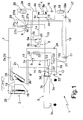
- Figure 1 shows, schematically, a heat-save cooler in accordance with the teachings of the present invention;
- Figure 2 shows a section, with parts removed for clarity, of a component part of the Figure 1 cooler.
-
- Number 1 in Figure 1 indicates as a whole a heat-save cooler, which may be used to advantage in centralized air conditioning systems of buildings; which systems normally comprise a number of fan convectors appropriately distributed within the building being temperature controlled, and at least one cooler for heating or cooling the heat-carrying liquid (normally water) conducted to the various fan convectors via the hydraulic circuit of the air conditioning system.
- In the following description, specific reference is made purely by way of example to a reversible-cycle heat-save cooler, and this is no way to be inferred as excluding single-cycle coolers. i.e. for simply cooling the heat-carrying liquid conducted to the fan convectors.
- Cooler 1 operates on the heat pump principle, by which heat is transferred from one environment to another by subjecting a gaseous cooling fluid to a closed thermodynamic cycle, such as the Carnot cycle. The thermodynamic principles on which the heat pump is based are widely known and therefore not described in detail.
- Cooler 1 comprises a
first heat exchanger 2 where the cooling fluid exchanges heat with the outside environment; a second heat exchanger 3 where the cooling fluid exchanges heat with the heat-carrying liquid conducted to the fan convectors via the hydraulic circuit of the air conditioning system; and athird heat exchanger 4 where the cooling fluid exchanges heat with a second liquid eventually used for other purposes not necessarily related to temperature control of the building, e.g. producing hot water for domestic use. - Cooler 1 also comprises a cooling
fluid compressor unit 5 where the cooling fluid is subjected to compression (e.g. adiabatic compression) so that the pressure of the cooling fluid leavingcompressor unit 5 is greater than the pressure of the cooling fluid entering the compressor unit; and a cooling fluid distributor 6 for selectively and appropriately connecting, on command, thedelivery side 5a andintake side 5b ofcompressor unit 5 toheat exchangers 2 and 3. - More specifically, distributor 6 selectively connects
delivery side 5a andintake side 5b ofcompressor unit 5 toheat exchangers 2 and 3 to enable cooler 1 to selectively: - cool the heat-carrying liquid circulating in the hydraulic circuit of the air conditioning system, so as to transfer heat to the outside environment;
- cool the heat-carrying liquid circulating in the hydraulic circuit of the air conditioning system, so as to transfer heat to the outside environment and/or to the liquid eventually used for other purposes not directly related to temperature control of the building;
- heat the heat-carrying liquid circulating in the hydraulic circuit of the air conditioning system, so as to withdraw heat from the outside environment; or
- heat the heat-carrying liquid circulating in the hydraulic circuit of the air conditioning system and the liquid eventually used for other purposes not necessarily related to temperature control of the building, so as to again withdraw heat from the outside environment.
- In the following description, specific reference is made, for the sake of simplicity, to the production of hot water for domestic use, though this in no way excludes use of the second liquid for other purposes.
-
Heat exchangers compressor unit 5 are devices widely used in the sector, and are therefore not described in detail. - With reference to Figure 1,
heat exchanger 2 permits heat exchange between the cooling fluid and outside environment, so as to produce condensation or evaporation of the cooling fluid, depending on the difference in temperature between the cooling fluid and outside environment. - More specifically, when the temperature of the cooling fluid entering
heat exchanger 2 is higher than that of the outside environment,heat exchanger 2 allows the cooling fluid flowing through it to cool gradually and yield heat to the outside environment, while the noncondensed part of the fluid passes from the gaseous to the liquid state. Conversely, when the temperature of the cooling fluid enteringheat exchanger 2 is lower than that of the outside environment,heat exchanger 2 allows the cooling fluid flowing through it to heat gradually and absorb heat from the outside environment, while passing from the liquid to the gaseous state. - In the example shown,
heat exchanger 2 has two inlets and two outlets for the cooling fluid, which are appropriately connected to each other to define, inheat exchanger 2, a cooling path, along which the high-temperature cooling fluid is gradually cooled and yields heat to the outside environment, while passing from the gaseous to the liquid state; and a heating path, along which the low-temperature cooling fluid is gradually heated and absorbs heat from the outside environment, while passing from the liquid to the gaseous state. - More specifically, in the example shown,
heat exchanger 2 is defined by a known, forced-air, external heat exchanger, which has aninlet 2a for high-temperature gaseous cooling fluid, anoutlet 2b for medium-temperature liquid cooling fluid, aninlet 2c for medium-temperature liquid cooling fluid, and anoutlet 2d for low-temperature gaseous cooling fluid, and which coincides withinlet 2a. -
Inlet 2a andoutlet 2b ofheat exchanger 2 define the ends of the cooling path;inlet 2a is connected directly to distributor 6 by a first connectingpipe 7; andoutlet 2b is connected directly to heat exchanger 3 by a second connectingpipe 8, along which are fitted a known non-return valve 9 and a known dehydration filter 10. Non-return valve 9 is so oriented as to only allow cooling fluid to flow fromheat exchanger 2 to dehydration filter 10. -
Inlet 2c andoutlet 2d ofheat exchanger 2, on the other hand, define the ends of the heating path;inlet 2c is connected directly to heat exchanger 3 by a connectingpipe 11 connected topipe 8 immediately downstream from dehydration filter 10; andoutlet 2d is connected directly to distributor 6 bypipe 7. - With reference to Figure 1, heat exchanger 3 permits heat exchange between the cooling fluid and the heat-carrying liquid supplied to the fan convectors, so as to increase or reduce the temperature of the cooling fluid by withdrawing or yielding heat from or to the heat-carrying liquid circulating in the air conditioning system.
- More specifically, when the temperature of the cooling fluid entering heat exchanger 3 is higher than that of the heat-carrying liquid, heat exchanger 3 allows the cooling fluid flowing through it to cool gradually and yield heat to, and so heat, the heat-carrying liquid. Conversely, when the temperature of the cooling fluid entering heat exchanger 3 is lower than that of the heat-carrying liquid, heat exchanger 3 allows the cooling fluid flowing through it to heat gradually and absorb heat from, and so cool, the heat-carrying liquid.
- Heat exchanger 3 has a primary circuit, along which flows the heat-carrying liquid conducted to the fan convectors of the air conditioning system; and a secondary circuit, along which the cooling fluid flows.
- The inlet and outlet of the primary circuit - hereinafter indicated 3a and 3b - are connected to the hydraulic circuit of the air conditioning system; and the inlet and outlet of the secondary circuit - hereinafter indicated 3c and 3d - are connected, one directly to
heat exchanger 2, and the other to distributor 6. - More specifically,
inlet 3c of heat exchanger 3 is connected directly topipe 8 with the interposition of a controlled on-offvalve 12 located immediately downstream from the junction ofpipes outlet 3d of heat exchanger 3 is connected directly to distributor 6 by a connectingpipe 13. -
Heat exchanger 4 permits heat exchange between the cooling fluid and water for domestic use, so that the cooling fluid is cooled by yielding heat to, and so heating, the domestic water. - In this case, the temperature of the cooling fluid entering
heat exchanger 4 is always higher than that of the domestic water, so that the cooling fluid flowing throughheat exchanger 4 is cooled gradually and yields heat to the domestic water, but not vice versa. - Like heat exchanger 3,
heat exchanger 4 has a primary circuit, along which flows the domestic water to be heated; and a secondary circuit, along which the cooling fluid flows. - The inlet and outlet of the primary circuit - hereinafter indicated 4a and 4b - are obviously connected to the hydraulic circuit of the building; and the inlet and outlet of the secondary circuit - hereinafter indicted 4c and 4d - are connected, one to the
delivery side 5a ofcompressor unit 5, and the other to distributor 6, so as to connectheat exchanger 4 immediately downstream fromcompressor unit 5. - More specifically,
inlet 4c ofheat exchanger 4 is connected by apipe 14 directly todelivery side 5a ofcompressor unit 5; andoutlet 4d ofheat exchanger 4 is connected to distributor 6 by a connectingpipe 15, which is fitted with anon-return valve 16 oriented to only permit cooling fluid flow fromheat exchanger 4 to distributor 6. - With reference to Figures 1 and 2, along
pipe 15, cooler 1 also comprises a liquid-gas separatingunit 17 for retaining the liquid cooling fluid issuing fromheat exchanger 4, so as to prevent the liquid cooling fluid from flowing alongpipe 15 to distributor 6. The separating unit is substantially defined by a liquid-gas separatingtank 18 located alongpipe 15, immediately downstream from heat exchanger 4 (i.e. upstream from non-return valve 16), to continually separate the liquid cooling fluid from the gaseous cooling fluid, and to retain inside it all the liquid cooling fluid issuing fromheat exchanger 4. - Liquid-
gas separating tank 18 is widely used in this sector for other applications, and is therefore not described in detail, except to state that it has adrain outlet 18a at the bottom by which to draw off liquid cooling fluid accumulated inside the tank. - In addition, liquid-
gas separating unit 17 also comprises : a connectingpipe 19 which, by means of an end fork, connectsdrain outlet 18a of the tank to bothinlet 2c ofheat exchanger 2 andinlet 3c of heat exchanger 3; a controlled on-offvalve 20 located alongpipe 19, immediately downstream fromdrain outlet 18a, to control liquid cooling fluid flow from the liquid-gas separating tank; and anexpansion valve 21 for rapidly expanding the cooling fluid flowing alongpipe 19. - More specifically,
expansion valve 21 is located downstream from on-offvalve 20, and rapidly expands the cooling fluid flowing alongpipe 19 so that the pressure of the cooling fluid issuing fromexpansion valve 21 is lower than the pressure of the cooling fluid entering the valve. - With reference to Figures 1 and 2, liquid-
gas separating unit 17 preferably, though not necessarily, also comprises alevel switch 22 housed inside liquid-gas separatingtank 18 to open on-offvalve 20 when the liquid level inside liquid-gas separating tank 18 exceeds a predetermined threshold value; and twonon-return valves pipe 19 connected toinlet 3c of heat exchanger 3 to only permit cooling fluid flow to inlet 3c of heat exchanger 3, and the second of which is located along the end portion ofpipe 19 connected toinlet 2c ofheat exchanger 2 to only permit cooling fluid flow to inlet 2c ofheat exchanger 2. - With reference to Figure 1, cooling
fluid compressor unit 5 is, as stated, known, and comprises a conventional screw orpiston compressor 25 for gaseous fluids (or similar); and a liquid-gas separatingtank 26 located upstream from the intake side ofcompressor 25 to prevent the liquid cooling fluid from reaching the intake side of, and so irreparably damaging,compressor 25. Coolingfluid compressor unit 5 preferably, though not necessarily, also comprises a non-return valve (not shown) located immediately downstream fromdelivery side 5a ofcompressor 25 and so oriented as to only permit gaseous cooling fluid flow toheat exchanger 4. - With reference to Figure 1, in the example shown, distributor 6 of cooler 1 is defined by a conventional, electrically controlled, four-
way valve 27, which is driven by an electronic central control unit (not shown) of the cooler, together with on-offvalve 12 and possibly on-offvalve 20. - More specifically, four-
way valve 27 is a slide valve, which has four inlets selectively connectable directly with one another in pairs, and which can alternatively assume two distinct operating configurations enabling two of the four inlets of the valve to selectively and alternatively communicate directly with either one of the other two inlets of the valve. - In other words, four-
way valve 27 has two primary inlets and two secondary inlets; and the primary inlets can be connected selectively and alternatively to either one of the two secondary inlets of the valve, but can never communicate directly with each other. - More specifically, four-
way valve 27 has fourinlets inlet 27a communicates directly withinlet 27b, whileinlet 27c communicates directly withinlet 27d; in a second operating configuration,inlet 27a communicates directly withinlet 27d, whileinlet 27c communicates directly withinlet 27b. - As for connection of four-
way valve 27 to the other components of cooler 1,inlet 27a of four-way valve 27 is connected directly bypipe 15 to liquid-gas separating unit 17;inlet 27b is connected directly topipe 7;inlet 27c is connected directly by apipe 29 to liquid-gas separating tank 26 andintake side 5b ofcompressor unit 5; andinlet 27d of four-way valve 27 is connected directly topipe 13 from heat exchanger 3. - As will be clear,
inlets inlets way valve 27. - With reference to Figure 1, cooler 1 also has at least one
expansion valve 28 for rapidly expanding the cooling fluid, so as to complete the closed thermodynamic cycle in opposition tocompressor unit 5, which rapidly compresses the cooling fluid. - More specifically,
expansion valve 28 rapidly expands the in-transit cooling fluid, so that the pressure of the cooling fluid issuing fromexpansion valve 28 is lower than the pressure of the cooling fluid entering the valve, and is obviously located along the pipe connecting the heat exchanger in which the cooling fluid is cooled to the heat exchanger in which the cooling fluid is heated before returning tocompressor unit 5. - More specifically, in the example shown, cooler 1 comprises three expansion valves 28 : a
first expansion valve 28 is located alongpipe 8, betweeninlet 3c of heat exchanger 3 and on-offvalve 12; and a second andthird expansion valve 28 are located alongpipe 11, atinlet 2c ofheat exchanger 2. - With reference to Figure 1, in the example shown, cooler 1 also comprises a
bypass circuit 31, by which the cooling fluid frominlet 3c of heat exchanger 3 bypasses theexpansion valve 28 alongpipe 8.Bypass circuit 31 comprises a connectingpipe 32 having a first end branch connected topipe 8, betweeninlet 3c of heat exchanger 3 andexpansion valve 28, and a second end branch connected topipe 8, between non-return valve 9 and dehydration filter 10; a cooling fluid storage tank 33 located alongpipe 32; and anon-return valve 34 located alongpipe 32, between storage tank 33 andpipe 8. Thenon-return valve 34 is so oriented as to only allow cooling fluid flow from storage tank 33 to dehydration filter 10, but not vice versa. - Operation of cooler 1 will now be described, assuming it is initially in the summer configuration, i.e. in the operating mode in which it withdraws heat from the heat-carrying liquid at heat exchanger 3, and yields heat to the outside environment at
heat exchanger 2. - In this operating mode, on-off
valve 12 is in the open position, and four-way valve 27 is in the first operating position whereininlet 27a communicates directly withinlet 27b, andinlet 27c communicates directly withinlet 27d. - With reference to Figure 1, the cooling fluid from
compressor 25 flows successively throughpipe 14,heat exchanger 4,pipe 15, liquid-gas separating tank 18, andnon-return valve 16 toinlet 27a of four-way valve 27 of distributor 6. On reachinginlet 27a, the cooling fluid flows through four-way valve 27, out throughinlet 27b, and alongpipe 7 toinlet 2a ofheat exchanger 2, where it yields heat to the outside environment and is cooled. - The cooling fluid flows out of
heat exchanger 2 throughoutlet 2b and successively, alongpipe 8, through non-return valve 9, dehydration filter 10, on-offvalve 12 and, finally,expansion valve 28, where it is expanded rapidly before flowing throughinlet 3c of heat exchanger 3. - Inside heat exchanger 3, the cooling fluid absorbs heat from the heat-carrying liquid circulating in the hydraulic circuit of the air conditioning system, then flows along
pipe 13 to distributor 6, and from there back tocompressor 25 via liquid-gas separating tank 26. - More specifically, the cooling fluid from heat exchanger 3 flows along
pipe 13 toinlet 27d of four-way valve 27, out throughinlet 27c of the valve, and alongpipe 29 to liquid-gas separating tank 26 communicating directly with the intake side ofcompressor 25. - It should be pointed out that, in this operating mode,
outlet 3d of heat exchanger 3 communicates directly withintake side 5b ofcompressor unit 5, which is therefore able to draw in by suction not only the cooling fluid frompipe 8, but also all the cooling fluid inbypass circuit 31, i.e. inpipe 32 and storage tank 33. Given the orientation ofnon-return valve 34, emptyingbypass circuit 31 obviously has no effect on normal cooling fluid flow fromheat exchanger 2 alongpipe 8. - To heat the heat-carrying liquid circulating in the hydraulic circuit of the air conditioning system, i.e. to switch from the summer to the winter configuration, the electronic central control unit (not shown) governing operation of cooler 1 closes on-off
valve 12 and sets four-way valve 27 to the second operating position. - In which case, the cooling fluid from
compressor 25 flows successively throughpipe 14,heat exchanger 4,pipe 15, liquid-gas separating tank 18, andnon-return valve 16 toinlet 27a of four-way valve 27 of distributor 6, where it flows out throughinlet 27d of four-way valve 27 and alongpipe 13 into heat exchanger 3 throughoutlet 3d. - After yielding heat to the heat-carrying liquid circulating in heat exchanger 3, the cooling fluid flows out through
inlet 3c of heat exchanger 3; flows along an initial portion ofpipe 8 and is side-tracked intobypass circuit 31 before reachingexpansion valve 28 inpipe 8; flows alongpipe 32 and successively through storage tank 33 andnon-return valve 34; and eventually flows back topipe 8 upstream from dehydration filter 10.Expansion valve 28, in fact, prevents the cooling fluid from flowing alongpipe 8 directly to on-offvalve 12. - On reaching
pipe 8 once more, the cooling fluid flows through dehydration filter 10, and is then side-tracked alongpipe 11, along which it flows throughexpansion valves 28 before reachinginlet 2c ofheat exchanger 2. As in the previous cases, on flowing throughexpansion valves 28, the cooling fluid is subjected to rapid (e.g. isoenthalpic) expansion, thus bringing about a rapid fall in temperature. - Inside
heat exchanger 2, the cooling fluid is heated by absorbing heat from the outside environment, and flows out of the exchanger throughinlet 2d and alongpipe 7 toinlet 27b of four-way valve 27. - Inside four-
way valve 27, the cooling fluid is directed toinlet 27c of the valve, from which it flows alongpipe 29 to liquid-gas separating tank 26 communicating directly with the intake side ofcompressor 25. - As regards liquid-
gas separating unit 17, the liquid-gas separating tank 18 retains all the liquid cooling fluid issuing fromheat exchanger 4, regardless of whether all or part of the cooling fluid flowing throughheat exchanger 4 condenses and yields heat. - On detecting a liquid cooling fluid level in liquid-
gas separating tank 18 over and above a predetermined threshold,level switch 22 inside liquid-gas separating tank 18 opens on-offvalve 20 to allow the liquid cooling fluid to flow alongpipe 19 toexpansion valve 21. - At this point, the liquid cooling fluid is subjected to rapid (e.g. isoenthalpic) expansion, thus bringing about a rapid fall in pressure and temperature.
- Because of the two
non-return valves pipe 19, and the difference in pressure at the ends of the two end portions ofpipe 19, the cooling fluid issuing fromexpansion valve 21 is forced towardsinlet 2c/3c of theheat exchanger 2/3 currently operating as an evaporator, i.e. towards the inlet of the heat exchanger in which the cooling fluid is able to absorb heat to increase its own temperature and pass entirely to the gaseous state. - The advantages of cooler 1 are obvious: liquid-
gas separating unit 17 immediately downstream fromheat exchanger 4 provides for disassociating the quantity of cooling fluid in cooler 1 from operation with or without heat saving by means ofheat exchanger 4, so that cooler 1 can be loaded with the amount of cooling fluid actually required for correct operation, as in the absence ofheat exchanger 4. - That is, liquid-
gas separating unit 17 provides for eliminating the auxiliary liquid cooling fluid storage tank and everything connected to it, thus greatly improving reliability of the cooler as a whole. - Clearly, changes may be made to cooler 1 as described and illustrated herein without, however, departing from the scope of the present invention.
- In particular, as stated, heat-save cooler 1 may be a single- as opposed to a reversible-cycle type, and therefore have no distributor 6 or any other summer-to-winter switching components, i.e. four-
way valve 27,bypass circuit 31, etc. In which case,pipe 15 is connected directly topipe 7, andpipe 13 is connected directly topipe 29.
Claims (8)
- A heat-save cooler (1) comprising a first heat exchanger (2) where a cooling fluid exchanges heat with the outside environment; a second heat exchanger (3) where said cooling fluid exchanges heat with a first liquid; a cooling fluid compressor unit (5) where said cooling fluid is compressed to increase its pressure; and a third heat exchanger (4) where said cooling fluid exchanges heat with a second liquid; said third heat exchanger (4) being located immediately downstream from said compressor unit (5); and the cooler (1) being characterized by also comprising a liquid-gas separating unit (17) located immediately downstream from said third heat exchanger (4) to retain the liquid cooling fluid issuing from said third heat exchanger (4).
- A cooler as claimed in Claim 1, characterized by also comprising a cooling fluid distributor (6) for appropriately connecting said third heat exchanger (4) and said compressor unit (5) to said first (2) and said second (3) heat exchanger.
- A cooler as claimed in Claim 1 or 2, characterized in that said liquid-gas separating unit (17) comprises a liquid-gas separating tank (18) located immediately downstream from said third heat exchanger (4) and for continually separating liquid cooling fluid from gaseous cooling fluid, and retaining inside it all the liquid cooling fluid issuing from said third heat exchanger (4).
- A cooler as claimed in Claim 3, characterized in that said liquid-gas separating tank (18) has a drain outlet (18a) by which to draw off liquid cooling fluid accumulated in the tank.
- A cooler as claimed in Claim 4, characterized in that said liquid-gas separating unit (17) also comprises a connecting pipe (19) for connecting said drain outlet (18a) of the liquid-gas separating tank (18) to both the inlet (2c) of said first heat exchanger (2) and the inlet (3c) of said second heat exchanger (3); a controlled on-off valve (20) located along the connecting pipe (19), downstream from said drain outlet (18a), to control liquid cooling fluid flow from said liquid-gas separating tank (18); and an expansion valve (21) for rapidly expanding the cooling fluid flowing along said connecting pipe (19).
- A cooler as claimed in Claim 5, characterized in that said liquid-gas separating unit (17) also comprises a level switch (22) for opening the on-off valve (20) when the liquid level in said liquid-gas separating tank (18) exceeds a predetermined threshold value.
- A cooler as claimed in Claim 5 or 6, characterized in that said liquid-gas separating unit (17) also comprises a first non-return valve (23) located along the end portion of the connecting pipe (19) communicating with the inlet (3c) of said second heat exchanger (3), so as to only permit cooling fluid flow to the inlet (3c) of the second heat exchanger (3); and a second non-return valve (24) located along the end portion of said connecting pipe (19) communicating with the inlet (2c) of said first heat exchanger (2), so as to only permit cooling fluid flow to the inlet (2c) of the first heat exchanger (2).
- A cooler as claimed in any one of Claims 2 to 7, characterized in that said cooling fluid distributor (6) comprises a four-way valve (27) having four inlets (27a, 27b, 27c, 27d) selectively connectable directly in pairs.
Applications Claiming Priority (2)
| Application Number | Priority Date | Filing Date | Title |
|---|---|---|---|
| ITTO20020982 | 2002-11-13 | ||
| IT000982A ITTO20020982A1 (en) | 2002-11-13 | 2002-11-13 | REFRIGERATING MACHINE WITH HEAT RECOVERY |
Publications (3)
| Publication Number | Publication Date |
|---|---|
| EP1420218A2 true EP1420218A2 (en) | 2004-05-19 |
| EP1420218A3 EP1420218A3 (en) | 2004-12-22 |
| EP1420218B1 EP1420218B1 (en) | 2008-09-10 |
Family
ID=32170753
Family Applications (1)
| Application Number | Title | Priority Date | Filing Date |
|---|---|---|---|
| EP03025862A Expired - Lifetime EP1420218B1 (en) | 2002-11-13 | 2003-11-11 | Heat-save cooler |
Country Status (5)
| Country | Link |
|---|---|
| EP (1) | EP1420218B1 (en) |
| AT (1) | ATE408103T1 (en) |
| DE (1) | DE60323443D1 (en) |
| ES (1) | ES2312712T3 (en) |
| IT (1) | ITTO20020982A1 (en) |
Cited By (2)
| Publication number | Priority date | Publication date | Assignee | Title |
|---|---|---|---|---|
| WO2013164036A1 (en) * | 2012-05-04 | 2013-11-07 | Carrier Corporation | Refrigeration circuit and heating and cooling system |
| CN111927759A (en) * | 2020-08-14 | 2020-11-13 | 烟台华顺机械工程设备有限公司 | Overhead traveling crane track auxiliary protection equipment suitable for high-temperature environment |
Citations (6)
| Publication number | Priority date | Publication date | Assignee | Title |
|---|---|---|---|---|
| US3324671A (en) * | 1966-04-19 | 1967-06-13 | Westinghouse Electric Corp | Refrigeration systems |
| US3461907A (en) * | 1966-08-18 | 1969-08-19 | Charles P Wood Jr | Liquid level control device for refrigeration systems |
| US5651265A (en) * | 1994-07-15 | 1997-07-29 | Grenier; Michel A. | Ground source heat pump system |
| US5758514A (en) * | 1995-05-02 | 1998-06-02 | Envirotherm Heating & Cooling Systems, Inc. | Geothermal heat pump system |
| US6427480B1 (en) * | 2000-04-26 | 2002-08-06 | Denso Corporation | Refrigerant cycle system |
| US6449964B1 (en) * | 2000-06-30 | 2002-09-17 | Vortex Aircon | Regenerative refrigeration system with mixed refrigerants |
-
2002
- 2002-11-13 IT IT000982A patent/ITTO20020982A1/en unknown
-
2003
- 2003-11-11 DE DE60323443T patent/DE60323443D1/en not_active Expired - Fee Related
- 2003-11-11 ES ES03025862T patent/ES2312712T3/en not_active Expired - Lifetime
- 2003-11-11 AT AT03025862T patent/ATE408103T1/en not_active IP Right Cessation
- 2003-11-11 EP EP03025862A patent/EP1420218B1/en not_active Expired - Lifetime
Patent Citations (6)
| Publication number | Priority date | Publication date | Assignee | Title |
|---|---|---|---|---|
| US3324671A (en) * | 1966-04-19 | 1967-06-13 | Westinghouse Electric Corp | Refrigeration systems |
| US3461907A (en) * | 1966-08-18 | 1969-08-19 | Charles P Wood Jr | Liquid level control device for refrigeration systems |
| US5651265A (en) * | 1994-07-15 | 1997-07-29 | Grenier; Michel A. | Ground source heat pump system |
| US5758514A (en) * | 1995-05-02 | 1998-06-02 | Envirotherm Heating & Cooling Systems, Inc. | Geothermal heat pump system |
| US6427480B1 (en) * | 2000-04-26 | 2002-08-06 | Denso Corporation | Refrigerant cycle system |
| US6449964B1 (en) * | 2000-06-30 | 2002-09-17 | Vortex Aircon | Regenerative refrigeration system with mixed refrigerants |
Cited By (3)
| Publication number | Priority date | Publication date | Assignee | Title |
|---|---|---|---|---|
| WO2013164036A1 (en) * | 2012-05-04 | 2013-11-07 | Carrier Corporation | Refrigeration circuit and heating and cooling system |
| CN111927759A (en) * | 2020-08-14 | 2020-11-13 | 烟台华顺机械工程设备有限公司 | Overhead traveling crane track auxiliary protection equipment suitable for high-temperature environment |
| CN111927759B (en) * | 2020-08-14 | 2022-02-11 | 烟台华顺机械工程设备有限公司 | Overhead traveling crane track auxiliary protection equipment suitable for high-temperature environment |
Also Published As
| Publication number | Publication date |
|---|---|
| ATE408103T1 (en) | 2008-09-15 |
| EP1420218A3 (en) | 2004-12-22 |
| DE60323443D1 (en) | 2008-10-23 |
| ES2312712T3 (en) | 2009-03-01 |
| EP1420218B1 (en) | 2008-09-10 |
| ITTO20020982A1 (en) | 2004-05-14 |
Similar Documents
| Publication | Publication Date | Title |
|---|---|---|
| CN100485290C (en) | Method and arrangement for defrosting vapor compression system | |
| EP2488804B1 (en) | Heating device with irreversible thermodynamic cycle for heating installations having high delivery temperature | |
| CN103175344A (en) | Cold-region used multi-connected heat pump system and control method thereof | |
| CN102645060A (en) | Multi-split air conditioning system | |
| CN108844250B (en) | Low-ambient-temperature air source heat pump system | |
| EP3296664B1 (en) | Air conditioner | |
| WO2014101225A1 (en) | Heat pump water heater | |
| JP2008196832A (en) | Expansion valve mechanism and passage switching device | |
| CN109323877B (en) | Heat exchanger comprehensive test system based on refrigeration cycle | |
| CN108759157B (en) | One-time throttling two-stage compression heat pump system | |
| EP2159511B1 (en) | Air conditioning system | |
| EP1420218B1 (en) | Heat-save cooler | |
| CN212457490U (en) | Secondary throttling double-condensation refrigerating system and air conditioner | |
| CN212457492U (en) | Triple throttling enthalpy-increasing double-condensation refrigerating system and air conditioner | |
| CN212457491U (en) | Triple throttling enthalpy-increasing double-condensation refrigerating system and air conditioner | |
| CN212778013U (en) | Double-enthalpy-increasing double-condensing three-stage compression refrigeration system and air conditioner | |
| CN108007010B (en) | Heat pump system | |
| CN209944563U (en) | Air conditioner | |
| CN209819923U (en) | Refrigeration, heating and hot water triple supply system | |
| CN109591545B (en) | Air-supplementing enthalpy-increasing heat pump system with throttling multi-port thermal expansion valve, vehicle and method | |
| KR102042218B1 (en) | Heat Pump | |
| CN111550944A (en) | Triple throttling enthalpy-increasing double-condensation refrigerating system, air conditioner and control method | |
| CN217715103U (en) | Double-circulation composite air source heat pump system | |
| JPS6146347Y2 (en) | ||
| CN212320082U (en) | High-efficiency heat pump water heater |
Legal Events
| Date | Code | Title | Description |
|---|---|---|---|
| PUAI | Public reference made under article 153(3) epc to a published international application that has entered the european phase |
Free format text: ORIGINAL CODE: 0009012 |
|
| AK | Designated contracting states |
Kind code of ref document: A2 Designated state(s): AT BE BG CH CY CZ DE DK EE ES FI FR GB GR HU IE IT LI LU MC NL PT RO SE SI SK TR |
|
| AX | Request for extension of the european patent |
Extension state: AL LT LV MK |
|
| PUAL | Search report despatched |
Free format text: ORIGINAL CODE: 0009013 |
|
| AK | Designated contracting states |
Kind code of ref document: A3 Designated state(s): AT BE BG CH CY CZ DE DK EE ES FI FR GB GR HU IE IT LI LU MC NL PT RO SE SI SK TR |
|
| AX | Request for extension of the european patent |
Extension state: AL LT LV MK |
|
| 17P | Request for examination filed |
Effective date: 20050621 |
|
| AKX | Designation fees paid |
Designated state(s): AT BE BG CH CY CZ DE DK EE ES FI FR GB GR HU IE IT LI LU MC NL PT RO SE SI SK TR |
|
| 17Q | First examination report despatched |
Effective date: 20071017 |
|
| GRAP | Despatch of communication of intention to grant a patent |
Free format text: ORIGINAL CODE: EPIDOSNIGR1 |
|
| GRAS | Grant fee paid |
Free format text: ORIGINAL CODE: EPIDOSNIGR3 |
|
| GRAA | (expected) grant |
Free format text: ORIGINAL CODE: 0009210 |
|
| AK | Designated contracting states |
Kind code of ref document: B1 Designated state(s): AT BE BG CH CY CZ DE DK EE ES FI FR GB GR HU IE IT LI LU MC NL PT RO SE SI SK TR |
|
| REG | Reference to a national code |
Ref country code: GB Ref legal event code: FG4D |
|
| REG | Reference to a national code |
Ref country code: CH Ref legal event code: EP |
|
| REG | Reference to a national code |
Ref country code: IE Ref legal event code: FG4D |
|
| REF | Corresponds to: |
Ref document number: 60323443 Country of ref document: DE Date of ref document: 20081023 Kind code of ref document: P |
|
| PGFP | Annual fee paid to national office [announced via postgrant information from national office to epo] |
Ref country code: DE Payment date: 20081022 Year of fee payment: 6 |
|
| PG25 | Lapsed in a contracting state [announced via postgrant information from national office to epo] |
Ref country code: AT Free format text: LAPSE BECAUSE OF FAILURE TO SUBMIT A TRANSLATION OF THE DESCRIPTION OR TO PAY THE FEE WITHIN THE PRESCRIBED TIME-LIMIT Effective date: 20080910 Ref country code: FI Free format text: LAPSE BECAUSE OF FAILURE TO SUBMIT A TRANSLATION OF THE DESCRIPTION OR TO PAY THE FEE WITHIN THE PRESCRIBED TIME-LIMIT Effective date: 20080910 Ref country code: SI Free format text: LAPSE BECAUSE OF FAILURE TO SUBMIT A TRANSLATION OF THE DESCRIPTION OR TO PAY THE FEE WITHIN THE PRESCRIBED TIME-LIMIT Effective date: 20080910 |
|
| PGFP | Annual fee paid to national office [announced via postgrant information from national office to epo] |
Ref country code: ES Payment date: 20081027 Year of fee payment: 6 |
|
| REG | Reference to a national code |
Ref country code: ES Ref legal event code: FG2A Ref document number: 2312712 Country of ref document: ES Kind code of ref document: T3 |
|
| NLV1 | Nl: lapsed or annulled due to failure to fulfill the requirements of art. 29p and 29m of the patents act | ||
| PG25 | Lapsed in a contracting state [announced via postgrant information from national office to epo] |
Ref country code: BE Free format text: LAPSE BECAUSE OF FAILURE TO SUBMIT A TRANSLATION OF THE DESCRIPTION OR TO PAY THE FEE WITHIN THE PRESCRIBED TIME-LIMIT Effective date: 20080910 |
|
| PGFP | Annual fee paid to national office [announced via postgrant information from national office to epo] |
Ref country code: IT Payment date: 20081120 Year of fee payment: 6 |
|
| PG25 | Lapsed in a contracting state [announced via postgrant information from national office to epo] |
Ref country code: BG Free format text: LAPSE BECAUSE OF FAILURE TO SUBMIT A TRANSLATION OF THE DESCRIPTION OR TO PAY THE FEE WITHIN THE PRESCRIBED TIME-LIMIT Effective date: 20081210 |
|
| PGFP | Annual fee paid to national office [announced via postgrant information from national office to epo] |
Ref country code: FR Payment date: 20081128 Year of fee payment: 6 |
|
| PG25 | Lapsed in a contracting state [announced via postgrant information from national office to epo] |
Ref country code: RO Free format text: LAPSE BECAUSE OF FAILURE TO SUBMIT A TRANSLATION OF THE DESCRIPTION OR TO PAY THE FEE WITHIN THE PRESCRIBED TIME-LIMIT Effective date: 20080910 Ref country code: NL Free format text: LAPSE BECAUSE OF FAILURE TO SUBMIT A TRANSLATION OF THE DESCRIPTION OR TO PAY THE FEE WITHIN THE PRESCRIBED TIME-LIMIT Effective date: 20080910 Ref country code: PT Free format text: LAPSE BECAUSE OF FAILURE TO SUBMIT A TRANSLATION OF THE DESCRIPTION OR TO PAY THE FEE WITHIN THE PRESCRIBED TIME-LIMIT Effective date: 20090210 Ref country code: CZ Free format text: LAPSE BECAUSE OF FAILURE TO SUBMIT A TRANSLATION OF THE DESCRIPTION OR TO PAY THE FEE WITHIN THE PRESCRIBED TIME-LIMIT Effective date: 20080910 Ref country code: SK Free format text: LAPSE BECAUSE OF FAILURE TO SUBMIT A TRANSLATION OF THE DESCRIPTION OR TO PAY THE FEE WITHIN THE PRESCRIBED TIME-LIMIT Effective date: 20080910 |
|
| PG25 | Lapsed in a contracting state [announced via postgrant information from national office to epo] |
Ref country code: MC Free format text: LAPSE BECAUSE OF NON-PAYMENT OF DUE FEES Effective date: 20081130 |
|
| REG | Reference to a national code |
Ref country code: CH Ref legal event code: PL |
|
| PLBE | No opposition filed within time limit |
Free format text: ORIGINAL CODE: 0009261 |
|
| STAA | Information on the status of an ep patent application or granted ep patent |
Free format text: STATUS: NO OPPOSITION FILED WITHIN TIME LIMIT |
|
| PG25 | Lapsed in a contracting state [announced via postgrant information from national office to epo] |
Ref country code: EE Free format text: LAPSE BECAUSE OF FAILURE TO SUBMIT A TRANSLATION OF THE DESCRIPTION OR TO PAY THE FEE WITHIN THE PRESCRIBED TIME-LIMIT Effective date: 20080910 Ref country code: DK Free format text: LAPSE BECAUSE OF FAILURE TO SUBMIT A TRANSLATION OF THE DESCRIPTION OR TO PAY THE FEE WITHIN THE PRESCRIBED TIME-LIMIT Effective date: 20080910 |
|
| 26N | No opposition filed |
Effective date: 20090611 |
|
| GBPC | Gb: european patent ceased through non-payment of renewal fee |
Effective date: 20081210 |
|
| PG25 | Lapsed in a contracting state [announced via postgrant information from national office to epo] |
Ref country code: CH Free format text: LAPSE BECAUSE OF NON-PAYMENT OF DUE FEES Effective date: 20081130 Ref country code: IE Free format text: LAPSE BECAUSE OF NON-PAYMENT OF DUE FEES Effective date: 20081111 Ref country code: LI Free format text: LAPSE BECAUSE OF NON-PAYMENT OF DUE FEES Effective date: 20081130 |
|
| PG25 | Lapsed in a contracting state [announced via postgrant information from national office to epo] |
Ref country code: GB Free format text: LAPSE BECAUSE OF NON-PAYMENT OF DUE FEES Effective date: 20081210 |
|
| PG25 | Lapsed in a contracting state [announced via postgrant information from national office to epo] |
Ref country code: SE Free format text: LAPSE BECAUSE OF FAILURE TO SUBMIT A TRANSLATION OF THE DESCRIPTION OR TO PAY THE FEE WITHIN THE PRESCRIBED TIME-LIMIT Effective date: 20081210 |
|
| PG25 | Lapsed in a contracting state [announced via postgrant information from national office to epo] |
Ref country code: CY Free format text: LAPSE BECAUSE OF FAILURE TO SUBMIT A TRANSLATION OF THE DESCRIPTION OR TO PAY THE FEE WITHIN THE PRESCRIBED TIME-LIMIT Effective date: 20080910 Ref country code: HU Free format text: LAPSE BECAUSE OF FAILURE TO SUBMIT A TRANSLATION OF THE DESCRIPTION OR TO PAY THE FEE WITHIN THE PRESCRIBED TIME-LIMIT Effective date: 20090311 Ref country code: LU Free format text: LAPSE BECAUSE OF NON-PAYMENT OF DUE FEES Effective date: 20081111 |
|
| REG | Reference to a national code |
Ref country code: FR Ref legal event code: ST Effective date: 20100730 |
|
| PG25 | Lapsed in a contracting state [announced via postgrant information from national office to epo] |
Ref country code: TR Free format text: LAPSE BECAUSE OF FAILURE TO SUBMIT A TRANSLATION OF THE DESCRIPTION OR TO PAY THE FEE WITHIN THE PRESCRIBED TIME-LIMIT Effective date: 20080910 |
|
| PG25 | Lapsed in a contracting state [announced via postgrant information from national office to epo] |
Ref country code: FR Free format text: LAPSE BECAUSE OF NON-PAYMENT OF DUE FEES Effective date: 20091130 Ref country code: GR Free format text: LAPSE BECAUSE OF FAILURE TO SUBMIT A TRANSLATION OF THE DESCRIPTION OR TO PAY THE FEE WITHIN THE PRESCRIBED TIME-LIMIT Effective date: 20081211 |
|
| PG25 | Lapsed in a contracting state [announced via postgrant information from national office to epo] |
Ref country code: DE Free format text: LAPSE BECAUSE OF NON-PAYMENT OF DUE FEES Effective date: 20100601 |
|
| REG | Reference to a national code |
Ref country code: ES Ref legal event code: FD2A Effective date: 20110307 |
|
| PG25 | Lapsed in a contracting state [announced via postgrant information from national office to epo] |
Ref country code: IT Free format text: LAPSE BECAUSE OF NON-PAYMENT OF DUE FEES Effective date: 20091111 |
|
| PG25 | Lapsed in a contracting state [announced via postgrant information from national office to epo] |
Ref country code: ES Free format text: LAPSE BECAUSE OF NON-PAYMENT OF DUE FEES Effective date: 20110304 |
|
| PG25 | Lapsed in a contracting state [announced via postgrant information from national office to epo] |
Ref country code: ES Free format text: LAPSE BECAUSE OF NON-PAYMENT OF DUE FEES Effective date: 20091112 |