EP1420195A2 - Continuously variable ratio drive - Google Patents
Continuously variable ratio drive Download PDFInfo
- Publication number
- EP1420195A2 EP1420195A2 EP03077045A EP03077045A EP1420195A2 EP 1420195 A2 EP1420195 A2 EP 1420195A2 EP 03077045 A EP03077045 A EP 03077045A EP 03077045 A EP03077045 A EP 03077045A EP 1420195 A2 EP1420195 A2 EP 1420195A2
- Authority
- EP
- European Patent Office
- Prior art keywords
- mobile element
- gearbox
- continuously variable
- variable ratio
- bush
- Prior art date
- Legal status (The legal status is an assumption and is not a legal conclusion. Google has not performed a legal analysis and makes no representation as to the accuracy of the status listed.)
- Granted
Links
Images


Classifications
-
- F—MECHANICAL ENGINEERING; LIGHTING; HEATING; WEAPONS; BLASTING
- F16—ENGINEERING ELEMENTS AND UNITS; GENERAL MEASURES FOR PRODUCING AND MAINTAINING EFFECTIVE FUNCTIONING OF MACHINES OR INSTALLATIONS; THERMAL INSULATION IN GENERAL
- F16H—GEARING
- F16H55/00—Elements with teeth or friction surfaces for conveying motion; Worms, pulleys or sheaves for gearing mechanisms
- F16H55/32—Friction members
- F16H55/52—Pulleys or friction discs of adjustable construction
- F16H55/56—Pulleys or friction discs of adjustable construction of which the bearing parts are relatively axially adjustable
-
- F—MECHANICAL ENGINEERING; LIGHTING; HEATING; WEAPONS; BLASTING
- F16—ENGINEERING ELEMENTS AND UNITS; GENERAL MEASURES FOR PRODUCING AND MAINTAINING EFFECTIVE FUNCTIONING OF MACHINES OR INSTALLATIONS; THERMAL INSULATION IN GENERAL
- F16H—GEARING
- F16H63/00—Control outputs from the control unit to change-speed- or reversing-gearings for conveying rotary motion or to other devices than the final output mechanism
- F16H63/02—Final output mechanisms therefor; Actuating means for the final output mechanisms
- F16H63/04—Final output mechanisms therefor; Actuating means for the final output mechanisms a single final output mechanism being moved by a single final actuating mechanism
- F16H63/06—Final output mechanisms therefor; Actuating means for the final output mechanisms a single final output mechanism being moved by a single final actuating mechanism the final output mechanism having an indefinite number of positions
- F16H63/062—Final output mechanisms therefor; Actuating means for the final output mechanisms a single final output mechanism being moved by a single final actuating mechanism the final output mechanism having an indefinite number of positions electric or electro-mechanical actuating means
Definitions
- the present invention refers to a continuously variable ratio drive.
- the invention refers to a gearbox with expandable conical pulleys using a transmission belt for a two-wheeled vehicle like a scooter.
- the principle upon which the operation of the gearbox is based is that of changing, moment by moment, the drive of the vehicle, as the load acting upon it (driver, fuel, baggage), the gradient of the road, the aerodynamic resistance, etc., vary.
- the gearbox is used to alter the rotation speed of the drive shaft to suit that of the driving wheel, and thus takes on the function of torque multiplier, i.e. a device which must provide greater "driving force" where the power of the motor is insufficient to drive forward the vehicle.
- torque we mean the rotation moment which the shaft can transmit, at each drive imparted upon the piston due to the explosion of the air-petrol mixture, said piston transferring to the shaft a force which, multiplied by the "crank arm”, generates a torque or rotation moment.
- the mechanical gearbox allows the best compromise between the resistances in operation and the speed of advancement to be sought after.
- the power delivered by the engine is sent to the driving wheel passing first from the primary transmission, then reaching the rear wheel of the motorcycle by means of the end transmission.
- stepless speed change gear which in the form of a centrifugal change gear, known simply as a "change gear" has become one of the most widespread transmission systems in small and medium cc motorcycles thanks to the advantages which it offers in terms of pickup and low running costs.
- Such a device is substantially a progressive gearbox capable of developing a continuous, and therefore infinite, range of ratios between a minimum and a maximum, established at the design stage.
- a varier consists of two pulleys and and a trapezoidal belt, each pulley consisting of two plates with a frusto-conical profile, facing each other so as to constitute a race upon which the transmission belt winds.
- the moving together and apart of the mobile plate with respect to the fixed one on the drive pulley causes, through the trapezoidal belt, the opposite displacement of the mobile plate on the driven pulley, the mobile plate which is kept pressed against the fixed one thanks to the force applied by a spring.
- the consequent variation of the winding radii of the trapezoidal belt on the pulleys generates the corresponding variation in the transmission ratio.
- CVTs Continuously variable ratios drive, or CVTs, are realised according to numerous types, all suitable for improving the performances of the vehicle thanks to an increase in the miles per gallon and a reduction in emissions, obtained thanks to the possibility of always keeping the motor on the best thermal yield values.
- Such automatic CVT gearboxes with respect to conventional gearboxes also allow a reduction in polluting emissions to be obtained.
- the movement of the mobile part of the drive pulley is realised by inertia by a centrifugal regulator system with a variable number of clutch balls or rollers, which therefore constrains the functionality not allowing the intervention of the driver or of suitable devices.
- the main purpose of the present invention is that of realising a Continuously variable ratio drive which does not have the aforementioned drawbacks of the prior art being totally controlled from the outside.
- such a gearbox allows different ways of operating which can be selected by the driver of the vehicle and which can be actuated under the control of an electronic gearcase.
- the continuously variable ratio drive of the type with expandable conical pulleys for an internal combustion engine comprises a pair of pulleys, one being a drive pulley and the other being a driven pulley, between which a transmission belt slides, the drive pulley in turn comprising an axially mobile element, and a fixed element both in the form of frusto-conical discs facing towards each other so as to constitute a groove in which the belt slides, the mobile element being operatively connected to an electric motor commanded and driven by an electronic unit and suitable for causing the axial movement of the mobile element through engagement of cylindrical pins, housed in holes formed in an outer bush placed in rotation by the electric motor, in helical slots formed in an inner bush bound axially to the outside of the mobile element.
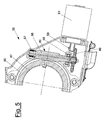
- an internal combustion engine 10 of the two or four stroke type is partially illustrated, the engine having, housed in a suitably shaped case 11, a continuously variable ratio drive of the type with expandable conical pulleys, generically indicated with 20.
- the continuously variable ratio drive 20 comprises two pairs of conical pulleys of which just the drive pulley 32 is illustrated, mounted on an entry shaft 51 of the gearbox.
- the illustrated drive pulley in turn comprises an axially mobile element 32', and a fixed element 32'' both in the form of frusto-conical discs and facing each other so as to constitute a groove in which a belt 31, preferably trapezoidal, slides.
- the mobile element 32' is moved axially, so as to vary the winding radii of the trapezoidal belt 31 on the drive and driven pulleys and consequently the transmission ratio.
- a suitable electric motor 61 through a suitable transmission realised as a non-exclusive example by a pair of conical wheels 59, 60, makes a shaft 56, carrying a worm screw 49, move, supported by tw rolling bearings 57 and 58.
- the worm screw 49 in turn makes a helical wheel 50 rotate integral with a cylindrical outer bush 47.
- an outer bush 47 is supported by a rolling bearing 45 at one end and rotates on a coaxial cylindrical inner bush 38.
- the rolling bearing 45 is mounted on a bush for holding bearings 44 and is locked through a ring nut 46.
- the bush for holding bearings 44 is bound onto the entry shaft 51 of the gearbox by a screw 52.
- the bearing 48 constitutes an additional support for all of the command system of the gearbox.
- the outer bush 47 carries housings which receive two or more cylindrical pins 37.
- the cylindrical pins 37 engage in helical slots 40 formed in the cylindrical inner bush 38.
- This bush 38 is locked against rotation through a flange 36, fixed to it rigidly, which carries a bush 54 in which a pin 53, fixed to the case 11 in the housing portion of the gearbox slides, through the interposition of a suitable ring 55 suitably made from an anti-friction material.
- the mobile element 32' of the drive pulley 32 is axially bound to the inner bush 38 through the interposition of a bearing 35.
- Such a mobile element 32' slides axially on the spacer 41, coaxial with the entry shaft 51 of the gearbox 20.
- the anti-friction bushes 33 are positioned between the spacer 41 and the mobile element 32' of the drive pulley 32.
- the mobile element 32' is bound to the entry shaft 51 of the gearbox through a sliding joint comprising a slide ring 42 and a plastic sliding block 43 radially fixed to the entry shaft 51 of the gearbox, said sliding block being arranged so as to engage in axial recesses 39 formed in the mobile element 32' of the drive pulley 32.
- the sliding joint 42, 43 is lubricated through suitable grease which contributes to improving the sliding of the anti-friction bushes 33 on the spacer 41, and which is suitably contained by an oil seal 34, mounted on one of the ends of the hole of the mobile mobile element 32' of the drive pulley 32 and by the screens of the rolling bearings 45.
- the gearbox 20 according to the preferred embodiment of the invention has the following operation.
- the electric motor 61 commanded by an electronic control unit, makes the shaft 56, carrying the worm screw 49, rotate.
- the worm screw 49 makes the helical wheel 50 rotate integral with the outer bush 47, which rotates on the bearing 45 and on the inner bush 38.
- Such an inner bush 38 cannot rotate on its own axis since the flange 36 is rigidly bound to it, at the ends of which the bush 54 is fixed and inside of which the pin 53, fixed to the wall of the case 11, slides, in such a way countering the tangential component of the forces between inner bush 38 and cylindrical pins 37.
- This axial movement can take place in the two directions, according to the direction of rotation of the outer bush 47, i.e. according to the direction of rotation of the electric motor 61 which commands the gearbox.
- the axial movement of the inner bush 38 is transferred to the mobile element 32' of the drive pulley 32 through the rolling bearing 35.
- This axial movement of the mobile element 32' causes the variation in the winding radius of the trapedoidal belt 31 and consequently the variation in the transmission ratio between the drive pulley 32 and the driven pulley.
- the drive torque is transferred from the entry shaft 51 of the gearbox to the mobile element 32' of the drive pulley 32 through the slider 42 and the sliding block 43.
- the gearbox 20 allows the aforementioned centrifugal speed varier to be replaced with a device which allows the way the gearbox operates to be controlled from the outside.
- Such a control provides different command possibilities of the gearbox, able to be selected freely by the driver of the vehicle and capable of being actuated as well as being controlable through an electronic gearcase.
Landscapes
- General Engineering & Computer Science (AREA)
- Engineering & Computer Science (AREA)
- Mechanical Engineering (AREA)
- Transmissions By Endless Flexible Members (AREA)
- Vehicle Body Suspensions (AREA)
- Control Of Transmission Device (AREA)
- Valve Device For Special Equipments (AREA)
- Threshing Machine Elements (AREA)
- Extrusion Moulding Of Plastics Or The Like (AREA)
- Transmission Devices (AREA)
- Valve-Gear Or Valve Arrangements (AREA)
- Liquid Crystal Substances (AREA)
- Primary Cells (AREA)
Abstract
Description
Claims (9)
- Continuously variable ratio drive of the type with expandable conical pulleys for internal combustion engines comprising a pair of pulleys, one being a drive pulley and the other being a driven pulley, between which a transmission belt (31) slides, the drive pulley (32) in turn comprising an axially mobile element (32'), and a fixed element (32'') both in the form of frusto-conical discs facing towards each other so as to constitute a groove in which the belt (31) slides, characterised in that said mobile element (32') is operatively connected to an electric motor (61) driven and controlled by an electronic unit and suitable for causing the axial movement of the mobile element (32') through engagement of cylindrical pins (37), housed in holes formed in an outer bush (47) placed in rotation by said electric motor (61), in helical slots (40) formed in an inner bush (38) bound axially to the outside of said mobile element (32').
- Continuously variable ratio drive according to claim 1, wherein said electric motor (61) is connected through a suitable transmission to a shaft (56) carrying a worm screw (49) suitable for transferring the motion to a helical wheel (50) integral with said outer bush (47).
- Continuously variable ratio drive according to claim 1, wherein said outer bush (47) is supported by a rolling bearing (45) at one end and rotates on said coaxial cylindrical inner bush (38).
- Continuously variable ratio drive according to claim 1, wherein said cylindrical inner bush (38) is locked against rotation through a flange (36) rigidly fixed to it carrying a bush (54) in which a pin (53) is slidably foreseen fixed to a case (11) housing the gearbox.
- Continuously variable ratio drive according to claim 1, wherein said mobile element (32') of the drive pulley (32) is axially bound to the inner bush (38), through the interposition of a bearing (35).
- Continuously variable ratio drive according to claim 5, wherein said mobile element (32') is arranged to slide axially on a spacer (41), arranged coaxial to the entry shaft (51) of the gearbox (20), with anti-friction bushes (33) being positioned between the spacer (41) and the mobile element (32').
- Continuously variable ratio drive according to claim 6, wherein said mobile element (32') is arranged bound to the entry shaft (51) of the gearbox through a sliding joint comprising a slide ring (42) and a sliding block (43) preferably made from plastic radially fixed to the entry shaft (51) of the gearbox, said sliding block (43) being arranged so as to engage in axial recesses (39) formed in the mobile element (32') of the drive pulley (32).
- Transmission system for an engine comprising a gearbox (20) according to any one of the previous claims.
- Motorised two-wheeled vehicle equipped with a transmission system comprising a gearbox (20) according to any one of claims 1 to 8.
Priority Applications (1)
| Application Number | Priority Date | Filing Date | Title |
|---|---|---|---|
| SI200331255T SI1420195T1 (en) | 2002-11-12 | 2003-06-30 | Continuously variable ratio drive |
Applications Claiming Priority (2)
| Application Number | Priority Date | Filing Date | Title |
|---|---|---|---|
| IT002391A ITMI20022391A1 (en) | 2002-11-12 | 2002-11-12 | CONTINUOUSLY CHANGED SPEED CHANGE |
| ITMI20022391 | 2002-11-12 |
Publications (3)
| Publication Number | Publication Date |
|---|---|
| EP1420195A2 true EP1420195A2 (en) | 2004-05-19 |
| EP1420195A3 EP1420195A3 (en) | 2005-06-08 |
| EP1420195B1 EP1420195B1 (en) | 2008-06-11 |
Family
ID=32170735
Family Applications (1)
| Application Number | Title | Priority Date | Filing Date |
|---|---|---|---|
| EP03077045A Expired - Lifetime EP1420195B1 (en) | 2002-11-12 | 2003-06-30 | Continuously variable ratio drive |
Country Status (10)
| Country | Link |
|---|---|
| EP (1) | EP1420195B1 (en) |
| CN (1) | CN100368704C (en) |
| AT (1) | ATE398253T1 (en) |
| DE (1) | DE60321529D1 (en) |
| DK (1) | DK1420195T3 (en) |
| ES (1) | ES2305399T3 (en) |
| IT (1) | ITMI20022391A1 (en) |
| PT (1) | PT1420195E (en) |
| SI (1) | SI1420195T1 (en) |
| TW (1) | TWI278407B (en) |
Cited By (5)
| Publication number | Priority date | Publication date | Assignee | Title |
|---|---|---|---|---|
| EP1614939A1 (en) * | 2004-07-08 | 2006-01-11 | Yamaha Hatsudoki Kabushiki Kaisha | Power unit |
| EP2108865A1 (en) * | 2004-07-08 | 2009-10-14 | Yamaha Hatsudoki Kabushiki Kaisha | Power unit and straddle-type vehicle provided with the power unit |
| CN101178026B (en) * | 2006-11-07 | 2010-06-09 | 本田技研工业株式会社 | Power unit |
| ITMI20112250A1 (en) * | 2011-12-13 | 2013-06-14 | Piaggio & C Spa | TRANSMISSION SYSTEM WITH DEVICE FOR ADJUSTING THE CHANGE CURVE |
| EP2685131A4 (en) * | 2011-03-08 | 2014-10-29 | Toyota Motor Co Ltd | TRANSMISSION WITH CONTINUOUS VARIATION OF BELT TYPE |
Families Citing this family (4)
| Publication number | Priority date | Publication date | Assignee | Title |
|---|---|---|---|---|
| JP4530926B2 (en) * | 2005-07-04 | 2010-08-25 | ヤマハ発動機株式会社 | Power unit and straddle-type vehicle equipped with the power unit |
| WO2012129417A1 (en) | 2011-03-22 | 2012-09-27 | Bombardier Recreational Products Inc. | Continuously variable transmission driving pulley |
| RU202842U1 (en) * | 2020-12-07 | 2021-03-10 | Евгений Николаевич Коптяев | MECHANICAL REDUCER |
| CN119079009A (en) * | 2024-11-08 | 2024-12-06 | 浙江新霸科技有限公司 | Speed changing system of a scooter |
Family Cites Families (7)
| Publication number | Priority date | Publication date | Assignee | Title |
|---|---|---|---|---|
| JPS5817248A (en) * | 1981-07-22 | 1983-02-01 | Nissan Motor Co Ltd | Stepless speed change engine auxiliary machinery driving apparatus |
| US4735598A (en) * | 1985-07-10 | 1988-04-05 | Aisin-Warner Kabushiki Kaisha | Continuously variable V-belt transmission |
| FR2657132B1 (en) * | 1990-01-12 | 1995-02-10 | Ibc Europ Eurl | SPEED DRIVE PULLEY EQUIPPED WITH A TRANSMISSION MEMBRANE. |
| JP2967374B2 (en) * | 1990-11-20 | 1999-10-25 | 本田技研工業株式会社 | Continuously variable transmission for vehicles |
| IT1297763B1 (en) * | 1997-07-10 | 1999-12-20 | Davide Boiani | DEVICE TO CONTROL A DISCRETIONALLY MODULABLE VARIATION OF THE GEAR RATIO OF A CONTINUOUS SPEED VARIANT. |
| CN2370220Y (en) * | 1998-07-17 | 2000-03-22 | 宋能训 | Slideway roller of driven wheel external shaft casing |
| JP4260278B2 (en) * | 1999-03-31 | 2009-04-30 | Nskワーナー株式会社 | V pulley control mechanism for belt type continuously variable transmission |
-
2002
- 2002-11-12 IT IT002391A patent/ITMI20022391A1/en unknown
-
2003
- 2003-06-30 DE DE60321529T patent/DE60321529D1/en not_active Expired - Lifetime
- 2003-06-30 ES ES03077045T patent/ES2305399T3/en not_active Expired - Lifetime
- 2003-06-30 AT AT03077045T patent/ATE398253T1/en not_active IP Right Cessation
- 2003-06-30 EP EP03077045A patent/EP1420195B1/en not_active Expired - Lifetime
- 2003-06-30 SI SI200331255T patent/SI1420195T1/en unknown
- 2003-06-30 DK DK03077045T patent/DK1420195T3/en active
- 2003-06-30 PT PT03077045T patent/PT1420195E/en unknown
- 2003-11-11 TW TW092131506A patent/TWI278407B/en not_active IP Right Cessation
- 2003-11-12 CN CNB2003101143095A patent/CN100368704C/en not_active Expired - Lifetime
Cited By (8)
| Publication number | Priority date | Publication date | Assignee | Title |
|---|---|---|---|---|
| EP1614939A1 (en) * | 2004-07-08 | 2006-01-11 | Yamaha Hatsudoki Kabushiki Kaisha | Power unit |
| EP2108865A1 (en) * | 2004-07-08 | 2009-10-14 | Yamaha Hatsudoki Kabushiki Kaisha | Power unit and straddle-type vehicle provided with the power unit |
| EP2290265A1 (en) * | 2004-07-08 | 2011-03-02 | Yamaha Hatsudoki Kabushiki Kaisha | Power unit and staddle-type vehicle provided with the power unit |
| CN101178026B (en) * | 2006-11-07 | 2010-06-09 | 本田技研工业株式会社 | Power unit |
| EP2685131A4 (en) * | 2011-03-08 | 2014-10-29 | Toyota Motor Co Ltd | TRANSMISSION WITH CONTINUOUS VARIATION OF BELT TYPE |
| ITMI20112250A1 (en) * | 2011-12-13 | 2013-06-14 | Piaggio & C Spa | TRANSMISSION SYSTEM WITH DEVICE FOR ADJUSTING THE CHANGE CURVE |
| WO2013098689A1 (en) * | 2011-12-13 | 2013-07-04 | Piaggio & C. S.P.A. | Transmission system with device for regulating the gear change curve |
| US9518641B2 (en) | 2011-12-13 | 2016-12-13 | Piaggio & C. S.P.A. | Transmission system with device for regulating the gear change curve |
Also Published As
| Publication number | Publication date |
|---|---|
| EP1420195A3 (en) | 2005-06-08 |
| ITMI20022391A1 (en) | 2004-05-13 |
| EP1420195B1 (en) | 2008-06-11 |
| TW200415067A (en) | 2004-08-16 |
| DK1420195T3 (en) | 2008-07-21 |
| ATE398253T1 (en) | 2008-07-15 |
| CN100368704C (en) | 2008-02-13 |
| TWI278407B (en) | 2007-04-11 |
| ES2305399T3 (en) | 2008-11-01 |
| DE60321529D1 (en) | 2008-07-24 |
| PT1420195E (en) | 2008-07-07 |
| SI1420195T1 (en) | 2008-08-31 |
| CN1501009A (en) | 2004-06-02 |
Similar Documents
| Publication | Publication Date | Title |
|---|---|---|
| CN1026432C (en) | Continuously variable transmission for vehicles | |
| EP2901043B1 (en) | Pneumatically assisted continuously variable transmission | |
| CA2439356C (en) | Driving pulley for a continuously variable transmission | |
| US6637283B2 (en) | Control apparatus for a continuously variable transmission | |
| CA2858205C (en) | Continuously variable transmission, clutch system, vehicle and method for controlling a transmission | |
| EP2263023B1 (en) | Planetary transmission | |
| US6494806B2 (en) | Lubricating oil supply system for infinitely variable transmission | |
| EP1420195B1 (en) | Continuously variable ratio drive | |
| TWI707098B (en) | A continuously variable transmission device with gear regulation device | |
| WO2010060184A1 (en) | Driving pulley of a continuously variable transmission | |
| US5582556A (en) | Variable ratio transmission | |
| US20130157793A1 (en) | Driven Clutch System | |
| EP1568922B1 (en) | Control system for a gearshift | |
| JP2003004108A (en) | Power transmission device for vehicles | |
| RU2805893C1 (en) | Disc-type variable drive | |
| EP4542083A1 (en) | Scissor-ramp mechanism for a continuously variable transmission | |
| JP2002372140A (en) | V-belt type continuously variable transmission | |
| KR101742640B1 (en) | Manual Transmission for two-wheel Vehicle | |
| KR100250284B1 (en) | Cvt apparatus for vehicles | |
| KR810001934B1 (en) | Automotive automatic transmission | |
| GB2565318A (en) | Toothed V-belt CVT | |
| JP2001182792A (en) | Continuously variable transmission for vehicles | |
| TH46927A (en) | Continuously variable transmission for automotive |
Legal Events
| Date | Code | Title | Description |
|---|---|---|---|
| PUAI | Public reference made under article 153(3) epc to a published international application that has entered the european phase |
Free format text: ORIGINAL CODE: 0009012 |
|
| AK | Designated contracting states |
Kind code of ref document: A2 Designated state(s): AT BE BG CH CY CZ DE DK EE ES FI FR GB GR HU IE IT LI LU MC NL PT RO SE SI SK TR |
|
| AX | Request for extension of the european patent |
Extension state: AL LT LV MK |
|
| PUAL | Search report despatched |
Free format text: ORIGINAL CODE: 0009013 |
|
| AK | Designated contracting states |
Kind code of ref document: A3 Designated state(s): AT BE BG CH CY CZ DE DK EE ES FI FR GB GR HU IE IT LI LU MC NL PT RO SE SI SK TR |
|
| AX | Request for extension of the european patent |
Extension state: AL LT LV MK |
|
| RIC1 | Information provided on ipc code assigned before grant |
Ipc: 7F 16H 63/06 B Ipc: 7F 16H 55/56 B Ipc: 7F 16H 61/00 A |
|
| 17P | Request for examination filed |
Effective date: 20051125 |
|
| AKX | Designation fees paid |
Designated state(s): AT BE BG CH CY CZ DE DK EE ES FI FR GB GR HU IE IT LI LU MC NL PT RO SE SI SK TR |
|
| GRAP | Despatch of communication of intention to grant a patent |
Free format text: ORIGINAL CODE: EPIDOSNIGR1 |
|
| GRAS | Grant fee paid |
Free format text: ORIGINAL CODE: EPIDOSNIGR3 |
|
| GRAA | (expected) grant |
Free format text: ORIGINAL CODE: 0009210 |
|
| AK | Designated contracting states |
Kind code of ref document: B1 Designated state(s): AT BE BG CH CY CZ DE DK EE ES FI FR GB GR HU IE IT LI LU MC NL PT RO SE SI SK TR |
|
| REG | Reference to a national code |
Ref country code: GB Ref legal event code: FG4D |
|
| REG | Reference to a national code |
Ref country code: CH Ref legal event code: EP |
|
| REG | Reference to a national code |
Ref country code: RO Ref legal event code: EPE |
|
| REG | Reference to a national code |
Ref country code: PT Ref legal event code: SC4A Free format text: AVAILABILITY OF NATIONAL TRANSLATION Effective date: 20080626 |
|
| REG | Reference to a national code |
Ref country code: GR Ref legal event code: EP Ref document number: 20080401658 Country of ref document: GR |
|
| REG | Reference to a national code |
Ref country code: DK Ref legal event code: T3 |
|
| REF | Corresponds to: |
Ref document number: 60321529 Country of ref document: DE Date of ref document: 20080724 Kind code of ref document: P |
|
| PGFP | Annual fee paid to national office [announced via postgrant information from national office to epo] |
Ref country code: CH Payment date: 20080625 Year of fee payment: 6 Ref country code: CZ Payment date: 20080617 Year of fee payment: 6 Ref country code: DK Payment date: 20080627 Year of fee payment: 6 Ref country code: LU Payment date: 20080624 Year of fee payment: 6 |
|
| REG | Reference to a national code |
Ref country code: CH Ref legal event code: NV Representative=s name: BOHEST AG |
|
| REG | Reference to a national code |
Ref country code: SE Ref legal event code: TRGR |
|
| REG | Reference to a national code |
Ref country code: IE Ref legal event code: FG4D |
|
| PGFP | Annual fee paid to national office [announced via postgrant information from national office to epo] |
Ref country code: SI Payment date: 20080617 Year of fee payment: 6 Ref country code: TR Payment date: 20080618 Year of fee payment: 6 Ref country code: PT Payment date: 20080630 Year of fee payment: 6 Ref country code: MC Payment date: 20080626 Year of fee payment: 6 Ref country code: FI Payment date: 20080630 Year of fee payment: 6 Ref country code: BG Payment date: 20080624 Year of fee payment: 6 |
|
| PGFP | Annual fee paid to national office [announced via postgrant information from national office to epo] |
Ref country code: EE Payment date: 20080611 Year of fee payment: 6 Ref country code: IE Payment date: 20080611 Year of fee payment: 6 Ref country code: NL Payment date: 20080630 Year of fee payment: 6 |
|
| REG | Reference to a national code |
Ref country code: ES Ref legal event code: FG2A Ref document number: 2305399 Country of ref document: ES Kind code of ref document: T3 |
|
| PGFP | Annual fee paid to national office [announced via postgrant information from national office to epo] |
Ref country code: AT Payment date: 20080724 Year of fee payment: 6 Ref country code: RO Payment date: 20080624 Year of fee payment: 6 Ref country code: SK Payment date: 20080619 Year of fee payment: 6 |
|
| REG | Reference to a national code |
Ref country code: EE Ref legal event code: HC1A Ref document number: E002361 Country of ref document: EE |
|
| REG | Reference to a national code |
Ref country code: HU Ref legal event code: AG4A Ref document number: E003962 Country of ref document: HU |
|
| PGFP | Annual fee paid to national office [announced via postgrant information from national office to epo] |
Ref country code: BE Payment date: 20080709 Year of fee payment: 6 Ref country code: HU Payment date: 20080619 Year of fee payment: 6 |
|
| PGFP | Annual fee paid to national office [announced via postgrant information from national office to epo] |
Ref country code: CY Payment date: 20080613 Year of fee payment: 6 |
|
| PLBE | No opposition filed within time limit |
Free format text: ORIGINAL CODE: 0009261 |
|
| STAA | Information on the status of an ep patent application or granted ep patent |
Free format text: STATUS: NO OPPOSITION FILED WITHIN TIME LIMIT |
|
| 26N | No opposition filed |
Effective date: 20090312 |
|
| PGFP | Annual fee paid to national office [announced via postgrant information from national office to epo] |
Ref country code: GR Payment date: 20080626 Year of fee payment: 6 |
|
| PG25 | Lapsed in a contracting state [announced via postgrant information from national office to epo] |
Ref country code: IT Free format text: LAPSE BECAUSE OF NON-PAYMENT OF DUE FEES Effective date: 20080630 |
|
| BERE | Be: lapsed |
Owner name: PIAGGIO & C. S.P.A. Effective date: 20090630 |
|
| REG | Reference to a national code |
Ref country code: PT Ref legal event code: MM4A Free format text: LAPSE DUE TO NON-PAYMENT OF FEES Effective date: 20091231 |
|
| PG25 | Lapsed in a contracting state [announced via postgrant information from national office to epo] |
Ref country code: MC Free format text: LAPSE BECAUSE OF NON-PAYMENT OF DUE FEES Effective date: 20090630 Ref country code: FI Free format text: LAPSE BECAUSE OF NON-PAYMENT OF DUE FEES Effective date: 20090630 Ref country code: CZ Free format text: LAPSE BECAUSE OF NON-PAYMENT OF DUE FEES Effective date: 20090630 |
|
| REG | Reference to a national code |
Ref country code: CH Ref legal event code: PL |
|
| REG | Reference to a national code |
Ref country code: DK Ref legal event code: EBP |
|
| REG | Reference to a national code |
Ref country code: EE Ref legal event code: MM4A Ref document number: E002361 Country of ref document: EE Effective date: 20090630 |
|
| NLV4 | Nl: lapsed or anulled due to non-payment of the annual fee |
Effective date: 20100101 |
|
| REG | Reference to a national code |
Ref country code: SK Ref legal event code: MM4A Ref document number: E 3687 Country of ref document: SK Effective date: 20090630 |
|
| EUG | Se: european patent has lapsed | ||
| PG25 | Lapsed in a contracting state [announced via postgrant information from national office to epo] |
Ref country code: PT Free format text: LAPSE BECAUSE OF NON-PAYMENT OF DUE FEES Effective date: 20091231 Ref country code: CY Free format text: LAPSE BECAUSE OF NON-PAYMENT OF DUE FEES Effective date: 20090630 |
|
| REG | Reference to a national code |
Ref country code: IE Ref legal event code: MM4A Ref country code: SI Ref legal event code: KO00 Effective date: 20100224 |
|
| PG25 | Lapsed in a contracting state [announced via postgrant information from national office to epo] |
Ref country code: RO Free format text: LAPSE BECAUSE OF NON-PAYMENT OF DUE FEES Effective date: 20090630 Ref country code: HU Free format text: LAPSE BECAUSE OF NON-PAYMENT OF DUE FEES Effective date: 20090701 Ref country code: CH Free format text: LAPSE BECAUSE OF NON-PAYMENT OF DUE FEES Effective date: 20090630 Ref country code: IE Free format text: LAPSE BECAUSE OF NON-PAYMENT OF DUE FEES Effective date: 20090630 Ref country code: LI Free format text: LAPSE BECAUSE OF NON-PAYMENT OF DUE FEES Effective date: 20090630 Ref country code: EE Free format text: LAPSE BECAUSE OF NON-PAYMENT OF DUE FEES Effective date: 20090630 |
|
| PG25 | Lapsed in a contracting state [announced via postgrant information from national office to epo] |
Ref country code: SK Free format text: LAPSE BECAUSE OF NON-PAYMENT OF DUE FEES Effective date: 20090630 Ref country code: SI Free format text: LAPSE BECAUSE OF NON-PAYMENT OF DUE FEES Effective date: 20090701 |
|
| PG25 | Lapsed in a contracting state [announced via postgrant information from national office to epo] |
Ref country code: BE Free format text: LAPSE BECAUSE OF NON-PAYMENT OF DUE FEES Effective date: 20090630 Ref country code: AT Free format text: LAPSE BECAUSE OF NON-PAYMENT OF DUE FEES Effective date: 20090630 |
|
| PG25 | Lapsed in a contracting state [announced via postgrant information from national office to epo] |
Ref country code: NL Free format text: LAPSE BECAUSE OF NON-PAYMENT OF DUE FEES Effective date: 20100101 Ref country code: BG Free format text: FAILURE TO ELECT DOMICILE IN THE NATIONAL COUNTRY Effective date: 20091231 Ref country code: DK Free format text: LAPSE BECAUSE OF NON-PAYMENT OF DUE FEES Effective date: 20090630 |
|
| PG25 | Lapsed in a contracting state [announced via postgrant information from national office to epo] |
Ref country code: LU Free format text: LAPSE BECAUSE OF NON-PAYMENT OF DUE FEES Effective date: 20090630 |
|
| PG25 | Lapsed in a contracting state [announced via postgrant information from national office to epo] |
Ref country code: SE Free format text: LAPSE BECAUSE OF NON-PAYMENT OF DUE FEES Effective date: 20090701 |
|
| PGRI | Patent reinstated in contracting state [announced from national office to epo] |
Ref country code: IT Effective date: 20110616 |
|
| PGFP | Annual fee paid to national office [announced via postgrant information from national office to epo] |
Ref country code: SE Payment date: 20080630 Year of fee payment: 6 |
|
| PG25 | Lapsed in a contracting state [announced via postgrant information from national office to epo] |
Ref country code: TR Free format text: LAPSE BECAUSE OF NON-PAYMENT OF DUE FEES Effective date: 20090630 |
|
| REG | Reference to a national code |
Ref country code: GR Ref legal event code: ML Ref document number: 20080401658 Country of ref document: GR Effective date: 20130104 |
|
| PG25 | Lapsed in a contracting state [announced via postgrant information from national office to epo] |
Ref country code: GR Free format text: LAPSE BECAUSE OF NON-PAYMENT OF DUE FEES Effective date: 20130204 |
|
| PG25 | Lapsed in a contracting state [announced via postgrant information from national office to epo] |
Ref country code: GR Free format text: LAPSE BECAUSE OF NON-PAYMENT OF DUE FEES Effective date: 20090630 |
|
| REG | Reference to a national code |
Ref country code: FR Ref legal event code: PLFP Year of fee payment: 14 |
|
| REG | Reference to a national code |
Ref country code: FR Ref legal event code: PLFP Year of fee payment: 15 |
|
| REG | Reference to a national code |
Ref country code: FR Ref legal event code: PLFP Year of fee payment: 16 |
|
| PGFP | Annual fee paid to national office [announced via postgrant information from national office to epo] |
Ref country code: IT Payment date: 20220608 Year of fee payment: 20 Ref country code: GB Payment date: 20220621 Year of fee payment: 20 Ref country code: DE Payment date: 20220620 Year of fee payment: 20 |
|
| PGFP | Annual fee paid to national office [announced via postgrant information from national office to epo] |
Ref country code: FR Payment date: 20220627 Year of fee payment: 20 |
|
| PGFP | Annual fee paid to national office [announced via postgrant information from national office to epo] |
Ref country code: ES Payment date: 20220701 Year of fee payment: 20 |
|
| REG | Reference to a national code |
Ref country code: DE Ref legal event code: R071 Ref document number: 60321529 Country of ref document: DE |
|
| P01 | Opt-out of the competence of the unified patent court (upc) registered |
Effective date: 20230529 |
|
| REG | Reference to a national code |
Ref country code: GB Ref legal event code: PE20 Expiry date: 20230629 |
|
| REG | Reference to a national code |
Ref country code: ES Ref legal event code: FD2A Effective date: 20230726 |
|
| PG25 | Lapsed in a contracting state [announced via postgrant information from national office to epo] |
Ref country code: GB Free format text: LAPSE BECAUSE OF EXPIRATION OF PROTECTION Effective date: 20230629 Ref country code: ES Free format text: LAPSE BECAUSE OF EXPIRATION OF PROTECTION Effective date: 20230701 |