EP1420180A1 - Axialwaelzlager mit radialer Abstützung - Google Patents
Axialwaelzlager mit radialer Abstützung Download PDFInfo
- Publication number
- EP1420180A1 EP1420180A1 EP02102571A EP02102571A EP1420180A1 EP 1420180 A1 EP1420180 A1 EP 1420180A1 EP 02102571 A EP02102571 A EP 02102571A EP 02102571 A EP02102571 A EP 02102571A EP 1420180 A1 EP1420180 A1 EP 1420180A1
- Authority
- EP
- European Patent Office
- Prior art keywords
- roller bearing
- intermediate ring
- axial
- collar
- bearing according
- Prior art date
- Legal status (The legal status is an assumption and is not a legal conclusion. Google has not performed a legal analysis and makes no representation as to the accuracy of the status listed.)
- Granted
Links
- 238000005096 rolling process Methods 0.000 title claims description 22
- 230000002093 peripheral effect Effects 0.000 claims abstract description 9
- 239000000463 material Substances 0.000 claims description 10
- 229910000906 Bronze Inorganic materials 0.000 claims description 6
- 230000005540 biological transmission Effects 0.000 claims description 6
- 239000010974 bronze Substances 0.000 claims description 6
- KUNSUQLRTQLHQQ-UHFFFAOYSA-N copper tin Chemical compound [Cu].[Sn] KUNSUQLRTQLHQQ-UHFFFAOYSA-N 0.000 claims description 6
- 239000004033 plastic Substances 0.000 claims description 6
- 229920003023 plastic Polymers 0.000 claims description 6
- 229920006362 Teflon® Polymers 0.000 claims description 4
- 239000002184 metal Substances 0.000 claims description 4
- 229920003223 poly(pyromellitimide-1,4-diphenyl ether) Polymers 0.000 claims description 4
- 229910001369 Brass Inorganic materials 0.000 claims description 3
- 239000004642 Polyimide Substances 0.000 claims description 3
- 229920003997 Torlon® Polymers 0.000 claims description 3
- 239000010951 brass Substances 0.000 claims description 3
- 239000011248 coating agent Substances 0.000 claims description 3
- 238000000576 coating method Methods 0.000 claims description 3
- 229920001721 polyimide Polymers 0.000 claims description 3
- 229920001343 polytetrafluoroethylene Polymers 0.000 claims description 3
- 239000004810 polytetrafluoroethylene Substances 0.000 claims description 3
- 235000015095 lager Nutrition 0.000 description 5
- 230000008878 coupling Effects 0.000 description 4
- 238000010168 coupling process Methods 0.000 description 4
- 238000005859 coupling reaction Methods 0.000 description 4
- 239000000945 filler Substances 0.000 description 3
- 238000005299 abrasion Methods 0.000 description 2
- 238000013459 approach Methods 0.000 description 2
- 238000001816 cooling Methods 0.000 description 2
- 238000013461 design Methods 0.000 description 2
- 125000006850 spacer group Chemical group 0.000 description 2
- OOKDYUQHMDBHMB-UHFFFAOYSA-N 3,6-dichloro-2-methoxybenzoic acid;2-(2,4-dichlorophenoxy)acetic acid;n-methylmethanamine Chemical compound CNC.CNC.COC1=C(Cl)C=CC(Cl)=C1C(O)=O.OC(=O)COC1=CC=C(Cl)C=C1Cl OOKDYUQHMDBHMB-UHFFFAOYSA-N 0.000 description 1
- 229910000897 Babbitt (metal) Inorganic materials 0.000 description 1
- OKTJSMMVPCPJKN-UHFFFAOYSA-N Carbon Chemical compound [C] OKTJSMMVPCPJKN-UHFFFAOYSA-N 0.000 description 1
- 229910000831 Steel Inorganic materials 0.000 description 1
- 230000004308 accommodation Effects 0.000 description 1
- 239000011324 bead Substances 0.000 description 1
- 238000006243 chemical reaction Methods 0.000 description 1
- 230000006735 deficit Effects 0.000 description 1
- 238000011161 development Methods 0.000 description 1
- 230000018109 developmental process Effects 0.000 description 1
- 230000000694 effects Effects 0.000 description 1
- 229910002804 graphite Inorganic materials 0.000 description 1
- 239000010439 graphite Substances 0.000 description 1
- 239000000314 lubricant Substances 0.000 description 1
- 238000011089 mechanical engineering Methods 0.000 description 1
- 238000000034 method Methods 0.000 description 1
- 210000001331 nose Anatomy 0.000 description 1
- 229920000642 polymer Polymers 0.000 description 1
- 239000010959 steel Substances 0.000 description 1
- 238000012360 testing method Methods 0.000 description 1
- 229920001169 thermoplastic Polymers 0.000 description 1
- 239000012815 thermoplastic material Substances 0.000 description 1
- 239000004416 thermosoftening plastic Substances 0.000 description 1
- 238000012546 transfer Methods 0.000 description 1
Images

Classifications
-
- F—MECHANICAL ENGINEERING; LIGHTING; HEATING; WEAPONS; BLASTING
- F16—ENGINEERING ELEMENTS AND UNITS; GENERAL MEASURES FOR PRODUCING AND MAINTAINING EFFECTIVE FUNCTIONING OF MACHINES OR INSTALLATIONS; THERMAL INSULATION IN GENERAL
- F16C—SHAFTS; FLEXIBLE SHAFTS; ELEMENTS OR CRANKSHAFT MECHANISMS; ROTARY BODIES OTHER THAN GEARING ELEMENTS; BEARINGS
- F16C19/00—Bearings with rolling contact, for exclusively rotary movement
- F16C19/54—Systems consisting of a plurality of bearings with rolling friction
- F16C19/545—Systems comprising at least one rolling bearing for radial load in combination with at least one rolling bearing for axial load
-
- F—MECHANICAL ENGINEERING; LIGHTING; HEATING; WEAPONS; BLASTING
- F16—ENGINEERING ELEMENTS AND UNITS; GENERAL MEASURES FOR PRODUCING AND MAINTAINING EFFECTIVE FUNCTIONING OF MACHINES OR INSTALLATIONS; THERMAL INSULATION IN GENERAL
- F16C—SHAFTS; FLEXIBLE SHAFTS; ELEMENTS OR CRANKSHAFT MECHANISMS; ROTARY BODIES OTHER THAN GEARING ELEMENTS; BEARINGS
- F16C19/00—Bearings with rolling contact, for exclusively rotary movement
- F16C19/22—Bearings with rolling contact, for exclusively rotary movement with bearing rollers essentially of the same size in one or more circular rows, e.g. needle bearings
- F16C19/30—Bearings with rolling contact, for exclusively rotary movement with bearing rollers essentially of the same size in one or more circular rows, e.g. needle bearings for axial load mainly
-
- F—MECHANICAL ENGINEERING; LIGHTING; HEATING; WEAPONS; BLASTING
- F16—ENGINEERING ELEMENTS AND UNITS; GENERAL MEASURES FOR PRODUCING AND MAINTAINING EFFECTIVE FUNCTIONING OF MACHINES OR INSTALLATIONS; THERMAL INSULATION IN GENERAL
- F16C—SHAFTS; FLEXIBLE SHAFTS; ELEMENTS OR CRANKSHAFT MECHANISMS; ROTARY BODIES OTHER THAN GEARING ELEMENTS; BEARINGS
- F16C19/00—Bearings with rolling contact, for exclusively rotary movement
- F16C19/22—Bearings with rolling contact, for exclusively rotary movement with bearing rollers essentially of the same size in one or more circular rows, e.g. needle bearings
- F16C19/34—Bearings with rolling contact, for exclusively rotary movement with bearing rollers essentially of the same size in one or more circular rows, e.g. needle bearings for both radial and axial load
- F16C19/38—Bearings with rolling contact, for exclusively rotary movement with bearing rollers essentially of the same size in one or more circular rows, e.g. needle bearings for both radial and axial load with two or more rows of rollers
- F16C19/381—Bearings with rolling contact, for exclusively rotary movement with bearing rollers essentially of the same size in one or more circular rows, e.g. needle bearings for both radial and axial load with two or more rows of rollers with at least one row for radial load in combination with at least one row for axial load
-
- F—MECHANICAL ENGINEERING; LIGHTING; HEATING; WEAPONS; BLASTING
- F16—ENGINEERING ELEMENTS AND UNITS; GENERAL MEASURES FOR PRODUCING AND MAINTAINING EFFECTIVE FUNCTIONING OF MACHINES OR INSTALLATIONS; THERMAL INSULATION IN GENERAL
- F16C—SHAFTS; FLEXIBLE SHAFTS; ELEMENTS OR CRANKSHAFT MECHANISMS; ROTARY BODIES OTHER THAN GEARING ELEMENTS; BEARINGS
- F16C19/00—Bearings with rolling contact, for exclusively rotary movement
- F16C19/22—Bearings with rolling contact, for exclusively rotary movement with bearing rollers essentially of the same size in one or more circular rows, e.g. needle bearings
- F16C19/44—Needle bearings
Definitions
- the invention relates to an axial roller bearing according to the preamble of claim 1.
- This measure is intended to ensure that the cage rotates when the Axial bearing between the discs can rotate freely and when lifting or at Re-approaching a disc does not exceed the forces occurring in the bearing entire cage, but only between the cage shelf and the two axially directed Collar of the running disks are transferred. This is not just intended to wear out reduced, but also the service life of such a camp with a filigree cage be increased considerably. However, the cage speed is not independent of the relative speeds of the thrust washers, which reduces the service life again.
- the bearings intended in particular for automotive transmissions should also be designed in this way be that the discs and the cage by a positive engagement behind one Unit are summarized. With such a complete component, the Assembly process much easier.
- the invention is therefore based on the problem of proposing an axial bearing with which at least low radial loads can be transmitted.
- the generic axial rolling bearing generally has at least one peripheral Edge of the disc on at least one collar and this is with the other Disc matched to each other so that a circumferential annular gap is created in an intermediate ring is arranged.
- the intermediate ring allows one over the Support the radial loads introduced, insofar as they are material-related does not exceed the specific limit values of the load capacity of the ring.
- each of the two discs to form a Provide an annular gap with a collar.
- the intermediate ring should consist of material selected from the group consisting of sintered bronze, brass, highly heat-resistant and low-wear plastics made of polyimide, in particular Vespel ® or Torlon ® and PTFE, especially Teflon®.
- the thermoplastic materials mentioned have in Trying the necessary longevity shown to be part of a centering bearing - Elements in automatic transmissions used in particular by motor vehicles become.
- Vespel ® brand of E.I. DuPont de Nemours and Co. US
- Torlon ® brand of Solvay Advanced Polymers, L.L.C., U.S.
- Teflon ® brand of E.I. DuPont de Nemours and Co. US
- fillers such as graphite in a suitable amount to the plastic at the close.
- the intermediate ring is approximately square Cross-section formed, so has a height-width ratio of 1. However, it can thinner intermediate rings up to a ratio of about 5% can also be used.
- Embodiments are also possible in which the intermediate ring is not separate is formed, but is connected to a running disk or a collar. This Connection or the ring can also be formed as a coating of a collar.
- the game should be 0.005 to 0.9 mm, but preferably 0.01 to Limited to 0.05 mm.
- the intermediate ring is as Rolling bearing cage is formed, the rolling elements support mainly in the radial direction.
- Conceivable as rolling elements are z.
- the two collars form advantageously a tread as parallel as possible.
- balls ball tracks are advantageously arranged in the flanges, but not so must be as pronounced as with a raidal ball bearing, since it is essentially about the axial support goes.
- the two collars have one corresponding inclination, advantageously the inclination with respect to the Axial direction is less than in known tapered roller bearings. The less the slope is, the better radial centering is achieved under axial load.
- a second or more rows of axial rolling elements can also be achieved be arranged, each separated by thrust washers.
- a similar effect will achieved when appropriate spacers between a washer and the axial rolling elements is used.
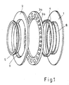
- FIG. 1 shows in perspective an axial needle roller bearing according to the invention Assembly.
- a running plate 1 made of sheet steel has on its inner peripheral Edge of a collar 8 on which an intermediate ring 4 made of the plastic Vespel ® can be put on.
- a needle roller cage 3a with pockets has bearing rollers 3b in the pockets for rolling on the running disks 1, 2.
- On a disc 2 with collar 9 This needle roller cage 3a can be put on its inner edge.
- cover plate 5 is placed over collar 8 pushed and thus secures the position of the intermediate ring 4.
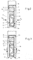
- the intermediate ring 4 sits within the cage in an annular gap 10 between the Collar 8 and 9 and has no play there.
- the needle roller cage 3a with rollers 3b is in axial direction of the running disks 1, 2 with the rolling surfaces 12, 13 and in radi aler Surrounded inward by the collar 9.
- the running disk 1 is open a paragraph of a component 7, not shown, while the disc 1 in is similarly connected to the component 6, not shown.
- the thrust bearing transmits axial forces FA from component 7 via a when components 6, 7 move relative common contact surface 14 to the coupled with it disc 1 and on the rolling surface 13 and the rollers 3b on the rolling surface 12 of the disc 2 and di e Coupling surface 11 to the component 6, so that a reaction force FA also arises there.
- Fig. 3 shows the same situation as in Fig. 2, but showing the transmission a radial load FR, which radially outwards in both directions shown or could be transmitted on the inside of both running disks 1, 2 via the components 6, 7, e.g. B. from the collar 8 via the intermediate ring 4 in the annular gap 10 on the coupling surface 23, on the coupling surface 22 further to the running disk 1 or its collar 9 and over Coupling surface or contact surface 21 to the component 6, not shown. Completeness for the sake of a bearing surface 24 between the disc 1 and component 7 is also shown.
- the intermediate ring e.g. B. made of the PTFE plastic Teflon®, thinner and had a height-width ratio of only 5 -15%
- the tests in the Operation a play of about 0.3 mm in the annular gap between the collars 8, 9.
- the collar 8 in the reduced annular gap instead of a separate one Intermediate ring, only to be provided with a coating of sintered bronze. The one there Damage-free radial loads were even higher, however running tolerance worsened.
- an annular gap was created between 0.05 and 0.8 mm.
- FIG. 4 shows an axial bearing which corresponds in structure to the bearing from FIGS. 2 and 3, but where the annular gap 10, and thus also the intermediate ring 4 and the collar 8 and 9th are arranged on the outer circumference of the thrust bearing.
- FIG. 5 An embodiment of the thrust bearing with two intermediate rings is shown in Fig. 5.
- Each disk 1 and 2 have collars 8 and 9 both on the inner radius and on the outer radius on.
- the intermediate ring 27 is designed as a bearing cage for rolling elements 28.
- the Rolling elements are arranged in the annular gap 10, the che by the two flans 8 and 9 of the Discs 1 and 2 is formed.
- two sets of rolling elements 3a arranged between the discs 1 and 2 the two sets by a free rotatable thrust washer 29 are separated.
- a sentence of Rolling elements 3a can also be replaced by a suitable spacer.
Landscapes
- Engineering & Computer Science (AREA)
- General Engineering & Computer Science (AREA)
- Mechanical Engineering (AREA)
- Rolling Contact Bearings (AREA)
Abstract
Description
- Fig. 1
- eine Explosionsdarstellung der wesentlichen T eile eines erfindungsgemäßen Axialwälzlagers;
- Fig. 2
- das Lager gemäß Fig. 1 im Teilschnitt nach den Zusammenbau mit Darstellung der Krafteinleitung bei Axiallast;
- Fig. 3
- das Lager gemäß Fig. 1 im Teilschnitt nach den Zusammenbau mit Darstellung der Krafteinleitung unter Radiallast,
- Fig. 4
- den Teilschnitt eines Lagers mit einem Kragen am äußeren Rand;
- Fig. 5
- den Teilschnitt eines Lagers mit Kragen an äußeren und inneren Rand und mit zwei Zwischenringen; und
- Fig. 6
- den Teilschnitt eines Lagers mit zwei Reihen Wälzkörpern und einem Zwischenring als Wälzlagerkäfig.
Claims (11)
dadurch gekennzeichnet,daß
mindestens an dem einem peripheren Rand der einen Laufscheibe (1, 2) mindestens eine Kragen (8, 9) und die andere Laufscheibe (1, 2) so aufeinander abgestimmt sind, daß ein umlaufender Ringspalt (10) entsteht, in dem ein Zwischenring (4) angeordnet ist.
dadurch gekennzeichnet,daß
der innere periphere Rand einer oder beider Laufscheiben (1, 2) einen Kragen (8, 9) aufweist.
dadurch gekennzeichnet,daß
der äußere periphere Rand einer oder beider Laufscheiben (1, 2) einen Kragen (8, 9) aufweist.
dadurch gekennzeichnet,daß
zumindest ein Ringspalte (10) zwischen Kragen (8, 9) an beiden Laufscheiben (1, 2) gebildet ist.
dadurch gekennzeichnet,daß
der Zwischenring (4) aus einem Material besteht, ausgewählt aus der Gruppe, umfassend, Sintermetall, insbesond ere Sinterbronze, Lagerbronze, Messing, hoch wärmebeständige und verschleißarme Kunststoffe aus Polyimid, insbesondere Vespel® oder Torlon® und PTFE, insbesondere Teflon® .
dadurch geke nnzeichnet,daß
der Zwischenring (4) ein Höhen -Breitenverhältnis von 1 nicht übersteigt.
dadurch gekennzeichnet,daß
der Zwischenring mit einer der Laufscheiben (1, 2) verbunden ist.
dadurch gekennzeichnet,daß
der Zwischenring als Beschichtung des Kragens einer der Laufscheiben ausgebildet ist.
dadurch gekennzeichnet,daß
der Zwischenring (27) als Wälzlager (28) aufnehmender Wälzlagerkäfig ausgebildet ist, wobei die Wälzkörper (28) hauptsächlich in radialer Richtung stützen.
dadurch gekennzeichnet, daß
für Anwendungen an Bauteilen mit höheren Betriebstemperaturen ein radiales Spiel im Ringspalt (10) bei eingefügtem Zwischenring (4) so eingestellt ist, daß es bei Raumtemperatur Null und bei Betriebstemperatur etwa zwischen 0,005 und 0,9 mm, vorzugsweise etwa 0,01 bis 0,05 mm beträgt.
Priority Applications (2)
| Application Number | Priority Date | Filing Date | Title |
|---|---|---|---|
| EP02102571A EP1420180B1 (de) | 2002-11-13 | 2002-11-13 | Axialwaelzlager mit radialer Abstützung |
| DE50210989T DE50210989D1 (de) | 2002-11-13 | 2002-11-13 | Axialwaelzlager mit radialer Abstützung |
Applications Claiming Priority (1)
| Application Number | Priority Date | Filing Date | Title |
|---|---|---|---|
| EP02102571A EP1420180B1 (de) | 2002-11-13 | 2002-11-13 | Axialwaelzlager mit radialer Abstützung |
Publications (2)
| Publication Number | Publication Date |
|---|---|
| EP1420180A1 true EP1420180A1 (de) | 2004-05-19 |
| EP1420180B1 EP1420180B1 (de) | 2007-09-26 |
Family
ID=32116318
Family Applications (1)
| Application Number | Title | Priority Date | Filing Date |
|---|---|---|---|
| EP02102571A Expired - Lifetime EP1420180B1 (de) | 2002-11-13 | 2002-11-13 | Axialwaelzlager mit radialer Abstützung |
Country Status (2)
| Country | Link |
|---|---|
| EP (1) | EP1420180B1 (de) |
| DE (1) | DE50210989D1 (de) |
Cited By (1)
| Publication number | Priority date | Publication date | Assignee | Title |
|---|---|---|---|---|
| DE102006031943A1 (de) * | 2006-07-11 | 2008-01-17 | Schaeffler Kg | Axialwälzlager |
Citations (4)
| Publication number | Priority date | Publication date | Assignee | Title |
|---|---|---|---|---|
| GB1187290A (en) * | 1966-12-08 | 1970-04-08 | Schaeffler Wilhelm | Improvements in Seals in Roller Thrust Bearings |
| EP0399259A1 (de) * | 1989-05-20 | 1990-11-28 | INA Wälzlager Schaeffler KG | Axial-Radialwälzlager |
| EP0597438A1 (de) * | 1992-11-12 | 1994-05-18 | Ford-Werke Aktiengesellschaft | Radial-Nadellager-Baueinheit mit integrierter Radial-Axialabdichtung und ggf. Axialabstützung |
| US5474390A (en) * | 1994-03-31 | 1995-12-12 | The Torrington Company | Thrust bearing assembly |
Family Cites Families (2)
| Publication number | Priority date | Publication date | Assignee | Title |
|---|---|---|---|---|
| DE3822779C1 (de) * | 1988-07-06 | 1989-08-24 | Ford-Werke Ag, 5000 Koeln, De | |
| DE19535085A1 (de) * | 1995-09-21 | 1997-03-27 | Schaeffler Waelzlager Kg | Axialwälzlager |
-
2002
- 2002-11-13 EP EP02102571A patent/EP1420180B1/de not_active Expired - Lifetime
- 2002-11-13 DE DE50210989T patent/DE50210989D1/de not_active Expired - Lifetime
Patent Citations (4)
| Publication number | Priority date | Publication date | Assignee | Title |
|---|---|---|---|---|
| GB1187290A (en) * | 1966-12-08 | 1970-04-08 | Schaeffler Wilhelm | Improvements in Seals in Roller Thrust Bearings |
| EP0399259A1 (de) * | 1989-05-20 | 1990-11-28 | INA Wälzlager Schaeffler KG | Axial-Radialwälzlager |
| EP0597438A1 (de) * | 1992-11-12 | 1994-05-18 | Ford-Werke Aktiengesellschaft | Radial-Nadellager-Baueinheit mit integrierter Radial-Axialabdichtung und ggf. Axialabstützung |
| US5474390A (en) * | 1994-03-31 | 1995-12-12 | The Torrington Company | Thrust bearing assembly |
Cited By (1)
| Publication number | Priority date | Publication date | Assignee | Title |
|---|---|---|---|---|
| DE102006031943A1 (de) * | 2006-07-11 | 2008-01-17 | Schaeffler Kg | Axialwälzlager |
Also Published As
| Publication number | Publication date |
|---|---|
| EP1420180B1 (de) | 2007-09-26 |
| DE50210989D1 (de) | 2007-11-08 |
Similar Documents
| Publication | Publication Date | Title |
|---|---|---|
| DE19839430C2 (de) | Radialkolbenpumpe | |
| EP1090233B1 (de) | Mehrreihiges radiallager | |
| EP1957812B1 (de) | Radialwälzlager, insbesondere einreihiges rillenwälzlager | |
| DE3743853A1 (de) | Innenlaufring eines kupplungsausruecklagers | |
| DE102007030217A9 (de) | Käfig | |
| EP1957811B1 (de) | Radialwälzlager, insbesondere einreihiges rillenwälzlager | |
| DE102007049050A1 (de) | Anordnung eines Radial-Nadellagers | |
| DE19680243C1 (de) | Klemmrollenfreilauf | |
| DE19535085A1 (de) | Axialwälzlager | |
| EP2325509B1 (de) | Wälzlager mit aus blech hergestellten lagerringen | |
| DE102008046237A1 (de) | Reibungsarmes Rollenlager | |
| WO2008116707A1 (de) | Radialwälzlager | |
| WO2008068123A1 (de) | Stützlager eines doppelkupplungsgetriebes | |
| EP1420180B1 (de) | Axialwaelzlager mit radialer Abstützung | |
| DE102019111105A1 (de) | Wälzlageranordnung | |
| EP2598762B1 (de) | Lageranordnung und getriebe | |
| DE102022106927A1 (de) | Kegelrollenlager und -anordnung | |
| DE102008047819A1 (de) | Laufrolle mit Zylinderrollenlagerung | |
| DE102023101298B4 (de) | Wälzlageranordnung und Lenksystem | |
| DE102023206387A1 (de) | Wälzlager, Tripoderoller mit Wälzlager sowie Verfahren zur Herstellung eines Wälzlagers | |
| DE102009052179A1 (de) | Lagerungseinheit zur Aufnahme radialer und axialer Kräfte, Verfahren zum Messen des Axialspiels der Lagerringe einer Lagerungseinheit sowie Abpassscheibe | |
| DE102020118220A1 (de) | Axialwälzlager | |
| DE102022115634A1 (de) | Zweireihiges Pendelrollenlager | |
| DE102009056260A1 (de) | Käfigsegment für einen Kunststoffkäfig eines Wälzlagers und Wälzlager mit einem solchen Käfigsegment | |
| DE102019133045A1 (de) | Axialwälzlager, Verfahren zur Herstellung eines Axialwälzlagers und Verfahren zur Demontage eines Axialwälzlagers |
Legal Events
| Date | Code | Title | Description |
|---|---|---|---|
| PUAI | Public reference made under article 153(3) epc to a published international application that has entered the european phase |
Free format text: ORIGINAL CODE: 0009012 |
|
| AK | Designated contracting states |
Kind code of ref document: A1 Designated state(s): AT BE BG CH CY CZ DE DK EE ES FI FR GB GR IE IT LI LU MC NL PT SE SK TR |
|
| AX | Request for extension of the european patent |
Extension state: AL LT LV MK RO SI |
|
| 17P | Request for examination filed |
Effective date: 20041119 |
|
| AKX | Designation fees paid |
Designated state(s): DE FR GB |
|
| 17Q | First examination report despatched |
Effective date: 20050112 |
|
| RAP1 | Party data changed (applicant data changed or rights of an application transferred) |
Owner name: FORD GLOBAL TECHNOLOGIES, LLC |
|
| RIN1 | Information on inventor provided before grant (corrected) |
Inventor name: FUSS, JOSEF Inventor name: PREMISKI, VLADIMIR |
|
| RAP1 | Party data changed (applicant data changed or rights of an application transferred) |
Owner name: FORD GLOBAL TECHNOLOGIES, LLC. |
|
| GRAP | Despatch of communication of intention to grant a patent |
Free format text: ORIGINAL CODE: EPIDOSNIGR1 |
|
| GRAS | Grant fee paid |
Free format text: ORIGINAL CODE: EPIDOSNIGR3 |
|
| GRAA | (expected) grant |
Free format text: ORIGINAL CODE: 0009210 |
|
| AK | Designated contracting states |
Kind code of ref document: B1 Designated state(s): DE FR GB |
|
| REG | Reference to a national code |
Ref country code: GB Ref legal event code: FG4D Free format text: NOT ENGLISH |
|
| REF | Corresponds to: |
Ref document number: 50210989 Country of ref document: DE Date of ref document: 20071108 Kind code of ref document: P |
|
| GBT | Gb: translation of ep patent filed (gb section 77(6)(a)/1977) | ||
| ET | Fr: translation filed | ||
| PLBE | No opposition filed within time limit |
Free format text: ORIGINAL CODE: 0009261 |
|
| STAA | Information on the status of an ep patent application or granted ep patent |
Free format text: STATUS: NO OPPOSITION FILED WITHIN TIME LIMIT |
|
| 26N | No opposition filed |
Effective date: 20080627 |
|
| PGFP | Annual fee paid to national office [announced via postgrant information from national office to epo] |
Ref country code: DE Payment date: 20091130 Year of fee payment: 8 |
|
| PGFP | Annual fee paid to national office [announced via postgrant information from national office to epo] |
Ref country code: FR Payment date: 20091120 Year of fee payment: 8 Ref country code: GB Payment date: 20091007 Year of fee payment: 8 |
|
| GBPC | Gb: european patent ceased through non-payment of renewal fee |
Effective date: 20101113 |
|
| REG | Reference to a national code |
Ref country code: FR Ref legal event code: ST Effective date: 20110801 |
|
| REG | Reference to a national code |
Ref country code: DE Ref legal event code: R119 Ref document number: 50210989 Country of ref document: DE Effective date: 20110601 Ref country code: DE Ref legal event code: R119 Ref document number: 50210989 Country of ref document: DE Effective date: 20110531 |
|
| PG25 | Lapsed in a contracting state [announced via postgrant information from national office to epo] |
Ref country code: FR Free format text: LAPSE BECAUSE OF NON-PAYMENT OF DUE FEES Effective date: 20101130 |
|
| PG25 | Lapsed in a contracting state [announced via postgrant information from national office to epo] |
Ref country code: GB Free format text: LAPSE BECAUSE OF NON-PAYMENT OF DUE FEES Effective date: 20101113 |
|
| PG25 | Lapsed in a contracting state [announced via postgrant information from national office to epo] |
Ref country code: DE Free format text: LAPSE BECAUSE OF NON-PAYMENT OF DUE FEES Effective date: 20110531 |