EP1420116A2 - Metal sheet pile - Google Patents
Metal sheet pile Download PDFInfo
- Publication number
- EP1420116A2 EP1420116A2 EP03021193A EP03021193A EP1420116A2 EP 1420116 A2 EP1420116 A2 EP 1420116A2 EP 03021193 A EP03021193 A EP 03021193A EP 03021193 A EP03021193 A EP 03021193A EP 1420116 A2 EP1420116 A2 EP 1420116A2
- Authority
- EP
- European Patent Office
- Prior art keywords
- metal sheet
- sheet pile
- pair
- flange
- hat
- Prior art date
- Legal status (The legal status is an assumption and is not a legal conclusion. Google has not performed a legal analysis and makes no representation as to the accuracy of the status listed.)
- Granted
Links
Images



Classifications
-
- E—FIXED CONSTRUCTIONS
- E02—HYDRAULIC ENGINEERING; FOUNDATIONS; SOIL SHIFTING
- E02D—FOUNDATIONS; EXCAVATIONS; EMBANKMENTS; UNDERGROUND OR UNDERWATER STRUCTURES
- E02D5/00—Bulkheads, piles, or other structural elements specially adapted to foundation engineering
- E02D5/02—Sheet piles or sheet pile bulkheads
- E02D5/03—Prefabricated parts, e.g. composite sheet piles
- E02D5/04—Prefabricated parts, e.g. composite sheet piles made of steel
Definitions
- the present invention relates to a metal sheet pile used for earth-retaining structures, fundamental structures, bank protection structures and a water cut-off walls in the civil engineering and construction fields.
- the present invention relates to the shape of a hat-type metal sheet pile.
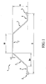
- Figure 1 illustrates the present invention; however, this figure will also be used below for explanation purposes to identify the various elements of a typical metal sheet pile according to the background art.
- this discussion is directed to the present inventors' analysis of the background art and should not be construed to be an admission of prior art.
- a hat-type metal sheet pile of the present invention includes a flange 2, a pair of webs 3, 3, a pair of arms 4, 4 and a pair of joints 5, 5.
- Each of the pair of webs 3, 3 is connected to a respective end of the flange 2 so as to be line-symmetric with each other.
- Each of the pair of arms 4, 4 is connected at one thereof to the other end of the pair of webs 3, 3, respectively.
- the pair of arms 4, 4 is parallel to the flange 2.
- each of the pair of joints 5, 5 is connected to the other end of the pair of arms 4,4, respectively.
- Figure 1 shows a hat-type metal sheet pile where an effective width is B [mm], a height is H [mm], a web width is Bw [mm], a flange width is Bf [mm] and a flange thickness is t [mm].
- the effective width B is defined as a distance between an interfitting center of a left joint 5 and an interfitting center of right joint 5.
- the interfitting center is defined as a center position of an area where a joint of one sheet pile and a joint of adjacent sheet pile overlap to interfit or interlock in the width direction of the sheet piles to form a pair of interfitted or interlocked joints.
- a hat-type metal sheet pile is typically manufactured by a well-known method, i.e., rolling a hot bloom or slab of a piece of metal, typically steel, which has been heated to about 1250°C in a furnace in advance.
- the rectangular hot piece of steel is passed a number of times using groove rolls, which have a complicated shape to form a final cross-section.
- the metal sheet pile having the final cross-section is cut-off to make a predetermined length product when at a high temperature and is then cooled down. Bending and/or a warping caused during the rolling process is/are eliminated by using a roller straightener or a press straightener.
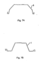
- Typical metal sheet piles are U-type metal sheet piles and a hat-type metal sheet piles. Outlines of U-type metal sheet piles and hat-type metal shape piles are shown in outline form in Figures 7A and 7B, respectively.
- a plurality of metal sheet piles are interlocked with each other by interfitting the joints 5. Therefore, it is economically advantageous to reduce the number of metal sheet piles by increasing the effective width B [mm] of a single metal sheet pile.
- the effective width of metal sheet piles according to the background art has been 600 mm at the maximum.
- Metal sheet piles are required to have a certain cross-sectional rigidity according to the intended use of the metal sheet pile.
- a geometrical moment of inertia I is more than 6,000 [cm 4 /m] (I > 6,000 [cm 4 /m]).
- An object of the present invention is to provide a hat-type metal sheet pile, which has more than a 700 mm effective width and a superior cross-section performance to a metal sheet pile according to the background art.
- Figure 2 is a graph illustrating a cross-sectional performance of background art metal sheet pile.
- the horizontal axis includes W [kg/m 2 ], a metal sheet pile weight per unit area of the wall of metal sheet pile, and the vertical axis shows the geometrical moment of inertia I [cm 4 /m].
- I ⁇ (470W - 38,000), wherein I has been calculated according to the following formula.
- I x ⁇ A y 2 dA
- y the distance from the gravity-center axis
- A the cross-sectional area of the metal sheet pile.
- a hat-type metal sheet pile which has more than a 700 mm effective width and a geometrical moment of inertia I [cm 4 /m] which is more than (470W - 38,000)
- the inventor of the present application has also examined the shape of a hat-type metal sheet pile which has a predetermined value of the geometrical moment of inertia I [cm 4 /m] and a predetermined effective width B [mm] by changing a height of the hat-type metal sheet pile in order to obtain a shape which can obtain a geometrical moment of inertia I [cm 4 /m], which is more than (470W - 38,000).
- a metal sheet pile according to the present invention comprises:
- a hat-type metal sheet pile of the present invention includes a flange 2, a pair of webs 3, 3, a pair of arms 4, 4 and a pair of joints 5, 5.
- Each of the pair of webs 3, 3 is connected to a respective end of the flange 2 so as to be line-symmetric with each other.
- Each of the pair of arms 4, 4 is connected at one thereof the other end of the pair of webs 3, 3, respectively.
- the pair of arms 4, 4 is parallel to the flange 2.
- each of the pair of joints 5, 5 is connected to the other end of the pair of arms 4,4, respectively.
- Figure 1 shows a hat-type metal sheet pile where an effective width is B mm, a height is H mm, a web width is Bw mm, a flange width is Bf mm and a flange thickness is t mm.
- the effective width B [mm] is defined as a distance between an interfitting center of a left joint 5 and an interfitting center of right joint 5.
- the interfitting center is defined as a center position of an area where a joint of one sheet pile and a joint of adjacent sheet pile overlap to interfit in the width direction of the sheet piles.
- a plurality of cross-sectional shapes of hat-type metal sheet piles which have a predetermined value of I [cm 4 /m] and a predetermined effective width B [mm], are determined by the following steps. First, one shape is tentatively fixed and I [cm 4 /m] is calculated based on the shape. Second, if the calculated value of I [cm 4 /m] is less than the predetermined value, a height of the shape is increased and/or a web angle is increased and then I [cm 4 /m] is calculated again. If the calculated value is more than the predetermined value, a height of the shape is decreased and/or a web angle is decreased and then I [cm 4 /m] is calculated.
- This calculation process is repeated until the calculated value becomes close enough to the predetermined value and to determine the final convergent shape.
- a predetermined value of geometrical moment of inertia I [cm 4 /m] 10,000 [cm 4 /m], 25,000 [cm 4 /m] and 45,000 [cm 4 /m] were selected.
- a predetermined effective width B [mm] 700 mm, 750 mm, 800 mm, 850 mm, 900 mm and 1,000 mm were selected.
- a hat-type metal sheet pile having a geometric moment of inertia I of 10,000 [cm 4 /m] and an effective width B of 700 mm is designed for a plurality of heights to determine the condition which meet the inequality I > 470W - 38,000.
- a hat-type metal sheet pile with I of 10,000 [cm 4 /m] and B of 750 mm is designed for a plurality of heights to determine the condition which meet the inequality I > 470W - 38,000. This operation is repeated with respect to other selected values of I [cm 4 /m] and B [mm] mentioned above, and all the conditions (all the shapes) which meet the inequality I > 470W - 38,000 are obtained.
- Figure 4 is a graph showing a relationship between the effective width B [mm] and (the flange width Bf [mm])/(the effective width B [mm]) with respect to a hat-type metal sheet pile with a predetermined value of I [cm 4 /m] and a predetermined effective width B [mm], which meets the inequality I > 470W - 38,000.
- An area under the approximate line in the graph meets the inequality I > 470W - 38,000.
- the aforementioned relationship between the effective width B [mm] and the flange width Bf [mm] was derived from examining the shape of a hat-type metal sheet pile which has a predetermined value of the geometrical moment of inertia I [cm 4 /m] and a predetermined effective width B [mm] by changing a height of the hat-type metal sheet pile. As long as the height is more than a certain value, the inequality; I >470W - 38,000 is met and the relationship between B and Bf is Bf/B ⁇ 0.0005B - 0.05 or Bf ⁇ 0.0005B 2 - 0.05B.
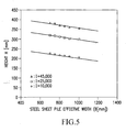
- Figure 5 is a graph showing a relationship between the effective width B [mm] and a lower limit of the height H [mm] to meet the relation of the inequality; I > 470W - 38,000 with respect to predetermined values of the geometrical moment of inertia I [cm 4 /m] and predetermined values of the effective width B [mm].
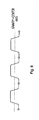
- Figure 8 illustrates outlines of several hat-type metal sheet piles, which are interlocked one after another to form a continuous metal wall. If the inequality; Bf x 0.6 ⁇ B - Bf - Bw x 2 ⁇ Bf x 1.1 is met, the gravity-center axis can be positioned approximately in the middle of the height of the metal sheet piles.
- the height H [mm] of a metal sheet pile is normally restricted to less than 380 mm because a metal sheet pile is manufactured by rolling a slab and an effective roll diameter of the rolling facility is restricted.
- the effective width B [mm] and the flange thickness t [mm] are limited to less than 1,200 mm and 28 mm, respectively, because of a limited rolling load capacity.
- Figure 6 illustrates a hat-type metal sheet pile and a vibrohammer chucking the sheet pile.
- a chucking device of a vibrohammer is 200 to 250 mm wide. Therefore the flange width should be more than 280 mm to allow for the chucking width of the vibrohammer, with a margin on each side remaining.
- the ratio of the flange width Bf [mm]/the flange thickness t [mm] is large, an applied load for driving the hat-type sheet pile may cause a local buckling or a local buckling may occur while the metal sheet piles are used as a wall, since the wall may collapse.
- the ratio, of the flange width Bf [mm]/the flange thickness t [mm] should be less than 32.4.
- hat-type metal sheet pile which meets all of the requirements or desired conditions set forth above can be determined as follows, where the hat-type metal sheet pile has a geometrical moment of inertia of 9,500 to 10,500 [cm 4 /m] and an effective width B of 890 to 920 [mm].
- the condition 280 ⁇ Bf ⁇ 0.0005 x B 2 -0.05 x B is always met, and if the height H is more than 210 [mm], the condition -0.073 x B + 0.0043 x I + 230 ⁇ H ⁇ 380 is always met (Upper limit of the height H could be 380 [mm] but actually 350 [mm] would be recommended for easier manufacturing.), then tentative values of the flange width Bf and the height H are determined so that the inequality Bf x 0.6 ⁇ B - Bf- Bw x 2 ⁇ Bf x 1.1 can be met, and a geometrical moment of inertia I can be calculated.
- the tentatively determined height and/or web angle can be changed to larger value to repeat the same calculation. If the calculated value of the geometrical moment of inertia I is more than 9,500 to 10,500, the tentatively determined height and/or web angle can be changed to smaller value to repeat the same calculation. These operations are repeated until the calculated value of I falls into the range of 9,500 to 10,500. The final shape of the sheet pile can then be fixed.
- a hat-type metal sheet pile having an effective width of more than 700 mm and excellent cross-section performance which has never been on the market, can be produced by designing the shape of the sheet pile so that the effective width B is between 700 and 1200 mm, the flange width Bf can meet the inequality condition 280 ⁇ Bf ⁇ 0.0005 x B 2 -0.05 x B, and the height H can meet another inequality condition -0.073 x B+0.0043 x I+230 ⁇ H ⁇ 380.
- hat-type metal sheet piles have been designed so as to meet the following three conditions.
- Other hat-shaped metal sheet piles have been designed for comparison without meeting some of the three conditions.
- Table 1 indicates the a hat-type metal sheet pile which meets the three conditions (examples 1-9) has a superior cross-sectional performance to that of a background art metal sheet pile, and a hat-type metal sheet pile without meeting some of the three conditions (comparative examples 10-16) are inferior to a background art metal sheet pile with respect to the cross-sectional performance.
Landscapes
- Engineering & Computer Science (AREA)
- Structural Engineering (AREA)
- Mining & Mineral Resources (AREA)
- Composite Materials (AREA)
- Life Sciences & Earth Sciences (AREA)
- General Life Sciences & Earth Sciences (AREA)
- Chemical & Material Sciences (AREA)
- Paleontology (AREA)
- Civil Engineering (AREA)
- General Engineering & Computer Science (AREA)
- Bulkheads Adapted To Foundation Construction (AREA)
- Reduction Rolling/Reduction Stand/Operation Of Reduction Machine (AREA)
- Paper (AREA)
Abstract
Description
a metal sheet pile according to the present invention comprises:
Bf x 0.6 ≤ B - Bf - Bw x 2 ≤ Bf x 1.1, wherein Bf is the flange width and B is the effective width.

Claims (6)
- A metal sheet pile comprising:wherein a cross-sectional dimension of said metal sheet pile meets all of the following inequalities:a flange;a pair of webs, each of said pair of webs being connected at one end thereof to opposite ends of said flange, respectively, so as to be line-symmetric with each other;a pair of arms, each of said pair of arms being connected at one end thereof to another end of said pair of webs, respectively; anda pair of joints, each of said pair of joints being connected to another end of said pair of arms, respectively,
- A metal sheet pile comprising:wherein the metal sheet pile has a geometrical moment of inertia I of 9,500 to 10,500 [cm4/m] and a cross-sectional dimension of said metal sheet pile meets all of the following inequalities:;a flange;a pair of webs, each of said pair of webs being connected at one end thereof to opposite ends of said flange, respectively, so as to be line-symmetric with each other;a pair of arms, each of said pair of arms being connected at one end thereof to another end of said pair of webs, respectively; anda pair of joints, each of said pair of joints being connected to another end of said pair of arms, respectively,
- The metal sheet pile according to claim 1 or 2, wherein the cross-sectional dimension of said metal sheet pile further meets the inequality
Bf x 0.6 ≤ B - Bf - 2 x Bw ≤ Bf x 1.1, where Bw is a width [mm] of said webs in the direction parallel to said flange. - The metal sheet pile according to any one of claims 1 to 3, wherein a thickness of the flange is less than 28 mm.
- The metal sheet pile according to any one of claims 1 to 4, wherein said metal sheet pile is made of steel.
- The metal sheet pile according to any one of claims 1 to 5, wherein said pair of arms is parallel to said flange.
Applications Claiming Priority (4)
| Application Number | Priority Date | Filing Date | Title |
|---|---|---|---|
| JP2002331761 | 2002-11-15 | ||
| JP2002331761A JP3458109B1 (en) | 2002-11-15 | 2002-11-15 | Hat-type steel sheet pile |
| JP2003204491A JP4069030B2 (en) | 2003-07-31 | 2003-07-31 | How to set the shape of a hat-type steel sheet pile |
| JP2003204491 | 2003-07-31 |
Publications (3)
| Publication Number | Publication Date |
|---|---|
| EP1420116A2 true EP1420116A2 (en) | 2004-05-19 |
| EP1420116A3 EP1420116A3 (en) | 2005-04-06 |
| EP1420116B1 EP1420116B1 (en) | 2017-05-31 |
Family
ID=32179159
Family Applications (1)
| Application Number | Title | Priority Date | Filing Date |
|---|---|---|---|
| EP03021193.2A Expired - Lifetime EP1420116B1 (en) | 2002-11-15 | 2003-09-24 | Metal sheet pile |
Country Status (4)
| Country | Link |
|---|---|
| US (1) | US6939086B2 (en) |
| EP (1) | EP1420116B1 (en) |
| KR (1) | KR100571076B1 (en) |
| CN (1) | CN1229553C (en) |
Cited By (1)
| Publication number | Priority date | Publication date | Assignee | Title |
|---|---|---|---|---|
| NL1032218C2 (en) * | 2006-07-20 | 2008-01-22 | Halteren Infra B V Van | Method for setting a sheet pile. |
Families Citing this family (24)
| Publication number | Priority date | Publication date | Assignee | Title |
|---|---|---|---|---|
| KR100711499B1 (en) * | 2005-12-22 | 2007-04-24 | 주식회사 포스코 | Connection-type high strength wide sheet pile |
| JP4927086B2 (en) * | 2006-09-05 | 2012-05-09 | 新日本製鐵株式会社 | Steel material for underground continuous wall, method for manufacturing steel material for underground continuous wall, underground continuous wall, and method for constructing underground continuous wall |
| CN102656319B (en) * | 2009-12-11 | 2014-10-01 | 杰富意钢铁株式会社 | Z-shaped steel sheet pile |
| JP5764945B2 (en) * | 2011-02-01 | 2015-08-19 | Jfeスチール株式会社 | Hat-shaped steel sheet pile |
| JP5500317B2 (en) * | 2011-07-14 | 2014-05-21 | 新日鐵住金株式会社 | Combination steel sheet pile and method of disassembling combination steel sheet pile |
| KR20140139050A (en) * | 2012-05-16 | 2014-12-04 | 제이에프이 스틸 가부시키가이샤 | Z-shaped steel sheet pile, and steel sheet pile wall formed from said z-shaped steel sheet pile |
| CN103572748B (en) * | 2012-07-27 | 2015-11-18 | 杰富意钢铁株式会社 | Hat steel sheet pile |
| KR101390883B1 (en) | 2012-07-27 | 2014-05-27 | 제이에프이 스틸 가부시키가이샤 | Hat-type steel sheet pile |
| JP6296199B1 (en) * | 2016-11-17 | 2018-03-20 | Jfeスチール株式会社 | Hat-shaped steel sheet pile and wall |
| TWI685601B (en) * | 2017-10-02 | 2020-02-21 | 日商日本製鐵股份有限公司 | Hat-shaped steel sheet pile |
| USD938811S1 (en) * | 2019-03-26 | 2021-12-21 | Richard Heindl | Sheet pile connector |
| USD938809S1 (en) * | 2019-03-26 | 2021-12-21 | Richard Heindl | Sheet pile connector |
| USD938810S1 (en) * | 2019-03-26 | 2021-12-21 | Richard Heindl | Sheet pile connector |
| USD938267S1 (en) * | 2019-03-26 | 2021-12-14 | Richard Heindl | Sheet pile connector |
| USD947015S1 (en) | 2020-07-22 | 2022-03-29 | Richard Heindl | Sheet pile connector |
| CN114134862B (en) * | 2021-11-05 | 2023-07-28 | 国网福建省电力有限公司 | Underwater trash device with water blocking function |
| USD1054844S1 (en) | 2023-02-06 | 2024-12-24 | Richard Heindl | Sheet pile |
| CA223291S (en) * | 2023-02-06 | 2025-04-07 | Heindl Richard | Sheet pile corner |
| CA223292S (en) * | 2023-02-06 | 2025-04-07 | Heindl Richard | Sheet pile corner |
| CA223293S (en) * | 2023-02-06 | 2024-09-24 | Heindl Richard | Sheet pile |
| JP1788671S (en) | 2024-04-02 | 2025-01-09 | Sheet pile connector | |
| UA47621S (en) | 2024-04-02 | 2025-07-10 | Гайндль Річард | 1. SHEET PILE |
| UA47620S (en) | 2024-04-02 | 2025-07-10 | Гайндль Річард | 1. SHEET PILE |
| USD1122739S1 (en) | 2024-04-02 | 2026-04-21 | Richard Heindl | Sheet pile connector |
Family Cites Families (7)
| Publication number | Priority date | Publication date | Assignee | Title |
|---|---|---|---|---|
| US1019227A (en) * | 1911-08-07 | 1912-03-05 | Armand Desoer | Metal sheeting-pile. |
| JPS6085326U (en) | 1983-11-10 | 1985-06-12 | 日本鋼管株式会社 | U-shaped steel sheet pile |
| AU649327B2 (en) * | 1991-04-29 | 1994-05-19 | Subterranean Systems Pte. Ltd. | Improvements to building construction methods and materials |
| JP2689794B2 (en) | 1991-11-15 | 1997-12-10 | 住友金属工業株式会社 | Asymmetric U-shaped steel sheet pile by hot rolling |
| JP2964933B2 (en) | 1995-07-31 | 1999-10-18 | 住友金属工業株式会社 | Underground structure, asymmetric U-shaped sheet pile, and method of placing asymmetric U-shaped sheet pile |
| JP3755296B2 (en) | 1998-05-25 | 2006-03-15 | 株式会社トーメック | How to hold hat-type retaining steel |
| GB9816698D0 (en) * | 1998-07-31 | 1998-09-30 | British Steel Plc | Steel sheet piling |
-
2003
- 2003-09-24 EP EP03021193.2A patent/EP1420116B1/en not_active Expired - Lifetime
- 2003-09-28 CN CNB031602363A patent/CN1229553C/en not_active Expired - Lifetime
- 2003-09-29 KR KR1020030067225A patent/KR100571076B1/en not_active Expired - Fee Related
- 2003-09-30 US US10/673,141 patent/US6939086B2/en not_active Expired - Lifetime
Cited By (2)
| Publication number | Priority date | Publication date | Assignee | Title |
|---|---|---|---|---|
| NL1032218C2 (en) * | 2006-07-20 | 2008-01-22 | Halteren Infra B V Van | Method for setting a sheet pile. |
| WO2008010701A1 (en) * | 2006-07-20 | 2008-01-24 | Van Halteren Infra B.V. | Method for bending a sheet pile wall |
Also Published As
| Publication number | Publication date |
|---|---|
| CN1229553C (en) | 2005-11-30 |
| CN1500942A (en) | 2004-06-02 |
| US6939086B2 (en) | 2005-09-06 |
| US20040101370A1 (en) | 2004-05-27 |
| KR100571076B1 (en) | 2006-04-14 |
| EP1420116B1 (en) | 2017-05-31 |
| EP1420116A3 (en) | 2005-04-06 |
| KR20040042807A (en) | 2004-05-20 |
Similar Documents
| Publication | Publication Date | Title |
|---|---|---|
| EP1420116A2 (en) | Metal sheet pile | |
| JP4528326B2 (en) | How to set the shape of a hat-type steel sheet pile | |
| KR100322317B1 (en) | Asymmetrical steel pile plate and its manufacturing method | |
| EP2677083A1 (en) | Metal sheet pile | |
| JP4069030B2 (en) | How to set the shape of a hat-type steel sheet pile | |
| CA1150986A (en) | Method for producing i-beam having centrally corrugated web and rolls for producing such i-beam | |
| JPS61262404A (en) | Hot rolling method for wide flange beam | |
| GB2071188A (en) | Steel H-sheet pile and producing method thereof | |
| US4367642A (en) | Method of producing H-beams | |
| US4550582A (en) | Method of producing steel H-sheet pile | |
| CN101522335B (en) | Method for bending sheet pile walls | |
| JP2001355286A (en) | Square steel pipe | |
| JP3064870B2 (en) | Rolling apparatus for section steel and method for rolling section steel using the apparatus | |
| JP7775149B2 (en) | Hat-shaped steel sheet pile | |
| JPH07178402A (en) | Method for manufacturing shaped steel for steel wall | |
| EP2140952A2 (en) | A method of roll-forming a pallet rack upright | |
| JPH11342401A (en) | Shape steel and its manufacturing method | |
| JPS6174708A (en) | Universal rolling mill | |
| JPH044902A (en) | Hot rolling method of h-shape steel | |
| JP2001340901A (en) | H-shaped sheet pile rolling method | |
| JP3272879B2 (en) | Rolling method of shaped steel with flange | |
| RU2312724C1 (en) | Shaped triangular tube | |
| JPH03142001A (en) | Manufacture of h-shaped steel having curved web | |
| WO2025174269A1 (en) | Z-shaped sheet pile | |
| RU2369458C1 (en) | Corrugated channeled sheet |
Legal Events
| Date | Code | Title | Description |
|---|---|---|---|
| PUAI | Public reference made under article 153(3) epc to a published international application that has entered the european phase |
Free format text: ORIGINAL CODE: 0009012 |
|
| 17P | Request for examination filed |
Effective date: 20031024 |
|
| AK | Designated contracting states |
Kind code of ref document: A2 Designated state(s): AT BE BG CH CY CZ DE DK EE ES FI FR GB GR HU IE IT LI LU MC NL PT RO SE SI SK TR |
|
| AX | Request for extension of the european patent |
Extension state: AL LT LV MK |
|
| PUAL | Search report despatched |
Free format text: ORIGINAL CODE: 0009013 |
|
| AK | Designated contracting states |
Kind code of ref document: A3 Designated state(s): AT BE BG CH CY CZ DE DK EE ES FI FR GB GR HU IE IT LI LU MC NL PT RO SE SI SK TR |
|
| AX | Request for extension of the european patent |
Extension state: AL LT LV MK |
|
| AKX | Designation fees paid |
Designated state(s): DE FR GB LU |
|
| 17Q | First examination report despatched |
Effective date: 20110121 |
|
| RAP1 | Party data changed (applicant data changed or rights of an application transferred) |
Owner name: NIPPON STEEL & SUMITOMO METAL CORPORATION |
|
| GRAP | Despatch of communication of intention to grant a patent |
Free format text: ORIGINAL CODE: EPIDOSNIGR1 |
|
| INTG | Intention to grant announced |
Effective date: 20160929 |
|
| GRAJ | Information related to disapproval of communication of intention to grant by the applicant or resumption of examination proceedings by the epo deleted |
Free format text: ORIGINAL CODE: EPIDOSDIGR1 |
|
| GRAP | Despatch of communication of intention to grant a patent |
Free format text: ORIGINAL CODE: EPIDOSNIGR1 |
|
| GRAJ | Information related to disapproval of communication of intention to grant by the applicant or resumption of examination proceedings by the epo deleted |
Free format text: ORIGINAL CODE: EPIDOSDIGR1 |
|
| GRAP | Despatch of communication of intention to grant a patent |
Free format text: ORIGINAL CODE: EPIDOSNIGR1 |
|
| INTG | Intention to grant announced |
Effective date: 20161125 |
|
| INTG | Intention to grant announced |
Effective date: 20161205 |
|
| GRAS | Grant fee paid |
Free format text: ORIGINAL CODE: EPIDOSNIGR3 |
|
| GRAA | (expected) grant |
Free format text: ORIGINAL CODE: 0009210 |
|
| AK | Designated contracting states |
Kind code of ref document: B1 Designated state(s): DE FR GB LU |
|
| REG | Reference to a national code |
Ref country code: GB Ref legal event code: FG4D |
|
| REG | Reference to a national code |
Ref country code: DE Ref legal event code: R081 Ref document number: 60350277 Country of ref document: DE Owner name: NIPPON STEEL CORPORATION, JP Free format text: FORMER OWNER: NIPPON STEEL CORP., TOKIO/TOKYO, JP |
|
| REG | Reference to a national code |
Ref country code: DE Ref legal event code: R096 Ref document number: 60350277 Country of ref document: DE |
|
| REG | Reference to a national code |
Ref country code: FR Ref legal event code: PLFP Year of fee payment: 15 |
|
| REG | Reference to a national code |
Ref country code: DE Ref legal event code: R097 Ref document number: 60350277 Country of ref document: DE |
|
| PLBE | No opposition filed within time limit |
Free format text: ORIGINAL CODE: 0009261 |
|
| STAA | Information on the status of an ep patent application or granted ep patent |
Free format text: STATUS: NO OPPOSITION FILED WITHIN TIME LIMIT |
|
| 26N | No opposition filed |
Effective date: 20180301 |
|
| REG | Reference to a national code |
Ref country code: FR Ref legal event code: PLFP Year of fee payment: 16 |
|
| REG | Reference to a national code |
Ref country code: DE Ref legal event code: R082 Ref document number: 60350277 Country of ref document: DE Representative=s name: VOSSIUS & PARTNER PATENTANWAELTE RECHTSANWAELT, DE Ref country code: DE Ref legal event code: R081 Ref document number: 60350277 Country of ref document: DE Owner name: NIPPON STEEL CORPORATION, JP Free format text: FORMER OWNER: NIPPON STEEL & SUMITOMO METAL CORPORATION, TOKYO, JP |
|
| PGFP | Annual fee paid to national office [announced via postgrant information from national office to epo] |
Ref country code: LU Payment date: 20220916 Year of fee payment: 20 Ref country code: GB Payment date: 20220804 Year of fee payment: 20 Ref country code: DE Payment date: 20220803 Year of fee payment: 20 |
|
| PGFP | Annual fee paid to national office [announced via postgrant information from national office to epo] |
Ref country code: FR Payment date: 20220808 Year of fee payment: 20 |
|
| REG | Reference to a national code |
Ref country code: DE Ref legal event code: R071 Ref document number: 60350277 Country of ref document: DE |
|
| REG | Reference to a national code |
Ref country code: GB Ref legal event code: PE20 Expiry date: 20230923 |
|
| PG25 | Lapsed in a contracting state [announced via postgrant information from national office to epo] |
Ref country code: GB Free format text: LAPSE BECAUSE OF EXPIRATION OF PROTECTION Effective date: 20230923 |