EP1419716A2 - Waffenschrank mit flexibler Inneneinrichtung - Google Patents
Waffenschrank mit flexibler Inneneinrichtung Download PDFInfo
- Publication number
- EP1419716A2 EP1419716A2 EP03026501A EP03026501A EP1419716A2 EP 1419716 A2 EP1419716 A2 EP 1419716A2 EP 03026501 A EP03026501 A EP 03026501A EP 03026501 A EP03026501 A EP 03026501A EP 1419716 A2 EP1419716 A2 EP 1419716A2
- Authority
- EP
- European Patent Office
- Prior art keywords
- safe
- module
- configurable
- clip
- gun
- Prior art date
- Legal status (The legal status is an assumption and is not a legal conclusion. Google has not performed a legal analysis and makes no representation as to the accuracy of the status listed.)
- Withdrawn
Links
Images


Classifications
-
- A—HUMAN NECESSITIES
- A47—FURNITURE; DOMESTIC ARTICLES OR APPLIANCES; COFFEE MILLS; SPICE MILLS; SUCTION CLEANERS IN GENERAL
- A47B—TABLES; DESKS; OFFICE FURNITURE; CABINETS; DRAWERS; GENERAL DETAILS OF FURNITURE
- A47B81/00—Cabinets or racks specially adapted for other particular purposes, e.g. for storing guns or skis
- A47B81/005—Devices for storing or displaying rifles, guns, pistols or elongated objects such as fishing rods storing fishing rods
-
- A—HUMAN NECESSITIES
- A47—FURNITURE; DOMESTIC ARTICLES OR APPLIANCES; COFFEE MILLS; SPICE MILLS; SUCTION CLEANERS IN GENERAL
- A47B—TABLES; DESKS; OFFICE FURNITURE; CABINETS; DRAWERS; GENERAL DETAILS OF FURNITURE
- A47B96/00—Details of cabinets, racks or shelf units not covered by a single one of groups A47B43/00 - A47B95/00; General details of furniture
- A47B96/06—Brackets or similar supporting means for cabinets, racks or shelves
- A47B96/067—Horizontal rails as suspension means in a cantilever arrangement
-
- A—HUMAN NECESSITIES
- A47—FURNITURE; DOMESTIC ARTICLES OR APPLIANCES; COFFEE MILLS; SPICE MILLS; SUCTION CLEANERS IN GENERAL
- A47B—TABLES; DESKS; OFFICE FURNITURE; CABINETS; DRAWERS; GENERAL DETAILS OF FURNITURE
- A47B97/00—Furniture or accessories for furniture, not provided for in other groups of this subclass
Definitions
- the present invention relates to a gun safe with a configurable interior. More particularly, the present invention relates to a gun safe having a unique modular gun rack, a versatile interior door storage system, and removable floor/storage compartment.
- conventional firearm safes provide non-movable firearm racks rigidly attached to the three interior walls of the safe.
- the firearm racks consist of a predetermined number of barrel receiving portions that protrude from the three interior walls into the safe.
- the racks define the number of long-arm guns that can be aligned against each wall and thereby, define and restrict utilization of the interior of the safe not occupied by the guns or occupied by guns having a peculiar shape.
- peripheral items such as scopes, barrels, pistols, cleaning equipment and paperwork in the safe.
- conventional firearm safes sometimes provide fixed shelves where these peripheral items can be placed, stacking these items on the shelves prohibits easy access, resulting in excessive time expended to locate these items.
- the floor of conventional fire arm safes is below, and not flush with the door opening, thereby forming a lower lip. When removing guns from the safe having such a floor design, the butt portion often collides with this lower lip, thereby damaging the gun.
- a safe having a unique modular gun rack, a versatile interior door storage system, and removable floor/storage compartment.
- the modular gun rack of the present invention includes one or more individual barrel receiving modules secured to the internal walls by a "Z" shaped bracket.
- This novel bracket provides versatility in the lateral placement of the receiving modules and allows for the secure mounting of the receiving modules to the walls of the safe without the use of known retention methods such as with screws or bolts.
- the receiving modules are also designed to receive various shaped gun barrels and can accommodate guns with scopes attached.
- the inside of the safe door includes bungee cord elements and cinches.
- the length of bungee cord is held in place by a series of knobs attached to the inside of the door.
- the bungee cord and cinches hold peripheral items such as gun barrels, scopes, and paperwork against the inside of the door.
- Storage bags are also provided.
- a unique floor is positioned flush with the door opening and is removable. The removable floor can be locked into place to provide an additional level of security for articles stored within the safe.
- FIG. 1 is a perspective view of a plurality of gun receiving modules and a corner receiving module according to the present invention
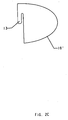
- FIG. 1b is a perspective view of a bracket that forms a part of the present invention.
- FIG. 1c is a side elevational view of the bracket shown in FIG. 1b and one of the gun receiving modules shown in FIG. 1a;
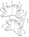
- FIG. 2a is a front perspective view of one of the gun receiving modules shown in FIG. 1a;
- FIG. 2b is a rear perspective view of the gun receiving module shown in FIG. 2a;
- FIG. 2c is a side elevational view of the gun receiving module shown in FIG. 2a;
- FIG. 2d is a perspective view of an alternative embodiment of the gun receiving module shown in FIG. 2a;
- FIG. 2e is a side elevational view of an extension module
- FIG. 2f is a side elevational view of another embodiment of a gun receiving module according to the present invention.
- FIG. 2g is a front perspective view of the gun receiving module shown in FIG. 2f;
- FIG. 2h is a front perspective view of yet another embodiment of a gun receiving module in accordance with the present invention.
- FIG. 2i is a front perspective view of yet another embodiment of a gun receiving module in accordance with the present invention.
- FIG. 2j is a front perspective view of the gun receive module shown in FIG. 2i;
- FIG. 2k is a front perspective view of another embodiment of a gun receiving module in accordance with the present invention.
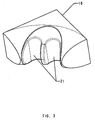
- FIG. 3 is a front perspective view of the corner receiving module in accordance with the present invention.
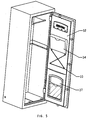
- FIG. 4 is a front perspective view of a safe showing the inside surface of its door including bungee cord elements and clinches in accordance with the present invention
- FIG. 4a is an enlarged view of the bottom portion of the safe door showing a bungee cord element and clinches positioned against the interior portion of a safe door;
- FIG. 5 is a front perspective view showing a plurality of knobs for fastening storage compartment to a cover for a safe door;
- FIG. 6 is a perspective view of a safe cover having storage bags coupled thereto;
- FIG. 7 is an enlarged view of the inside of a safe door showing a plurality of hook mounted thereto;
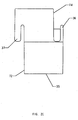
- FIG. 8 is a perspective view of a removable safe floor in accordance with the present invention.
- the interior gun rack of the present invention has one or more individual barrel receiving modules 10' and a corner receiving module 18 secured to interior walls 11 on a "Z" shaped bracket 12.
- Module 10' includes a clip 13 for attaching the module to wall 11 and a cradle 14' for receiving a gun barrel (not shown).
- FIGS. 2d and 2f-2g show a series of second embodiments including arcuate shaped barrel receiving modules 10'.
- FIGS. 2h-2k show yet other shaped modules.
- cradle 14' is uniquely shaped to receive many different barrel types. Barrel receiving modules 10' may also include optional straps for securing the gun barrel against the cradle. Strap ends are secured to the module while connecting means of straps, such as for example, snaps or Velcro, are used to join the straps together once the gun barrel is in place in a respective cradle.
- substantially rigid bracket 12 includes a first leg 45 and a second leg 46 connected by transition member 47 to thereby position second leg 46 parallel to but offset from first leg 45.
- First leg 45 of bracket 12 is secured to wall 11 of the safe by conventional attaching means 49 such as, for example, rivets, screw, bolts or welding.
- Second leg 46 of bracket 12 protrudes upward spaced from the wall 11 by transition member 47, forming a groove 48 between second leg 46 and wall 11.
- Thickness 20 of clip 13 is sized slightly less than thickness 26 of groove 48, while stock thickness 22 of bracket 12 is slightly less than gap 24 of clip 13.
- barrel receiving module 10' is mounted to wall 11 by simply sliding clip 13 of the barrel receiving module into the groove 48.
- This mechanism allows the barrel receiving module to be secured firmly against wall 11.
- the present invention allows the receiving module to be positioned and re-positioned anywhere laterally along bracket 12 and along the walls of the safe to accommodate the number of guns stored and a variety of gun barrel shapes and designs.
- receiving module 10' includes cradle 14' for receiving the barrel of a gun, and clip 13, for securing the individual barrel receiving module to bracket 12.
- bracket 12 is fixedly mounted on the internal walls 11 of the safe and, in turn, individual barrel receiving modules 10' are attached to bracket 12 by clip 13.
- cradle 14' includes a uniquely shaped concave recess to accommodate barrels of various gun types such as, but not limited to, double barrel, side-by-side, under and over, and the like.
- Cradle 14' may have a soft contact surface such as, for example, rubber to further protect the gun barrels from scratches or nicks.
- This soft contact surface can be either a separate piece or integrally attached or molded to the module 10'. While clip 13 is shown with three prongs spaced across the full width of the module in the above disclosed embodiments, it is contemplated that the clip of the present invention can instead include a single prong spaced across the width of the module.
- an extension is used to space the barrels a greater distance from the wall.
- One particular extension means is an extension module, having a coupling end and an extension cradle similar in contour to cradle 14'.
- the coupling end of the extension module is shaped to fit into the concave recess of cradle 14'.
- the extension module can be attached to receiving module 10' by a screw or screws, or by plastic spring clips and recesses molded into the modules.
- the cradle serves to position a received gun barrel a greater distance from the wall of the safe and thereby provides additional wall clearance for a barrel mounted scope.
- Double clip extender 35 has a first extension clip 37 extending from a first side 72 and a extension second clip 36 extending from a second side 74.
- the first extension clip 37 is sized for inserting into groove 48 of bracket 12 and the second extension clip 36 is sized for receiving clip 13 of barrel receiving module 10'.
- Second extension clip 36 is a reverse or mirror image of first extension clip 37 so that double extender 35 can be oriented in either direction.
- second extension clip 36 may also include a recess portion that is adapted to be positioned adjacent to clip 13 of receiving module 10' when clip extender 35 is coupled with receiving module 10'.
- receiving module 10" may also be elongated so that the cradle 14' is positioned further away from clip 13 compared to the receiving module 10' shown in FIG. 2a.
- Module 38 has a first cradle 40 for receiving barrels without scopes and second cradle 39 for receiving barrels with scopes.
- the module has a short side 41 and a long side 42 generally perpendicular to the short side.
- Short side 41 and long side 42 each have a clip 43, 44, respectively, for attaching module 38 to bracket 12 as described above.
- clip 44 is used to attach module 38 to bracket 12
- cradle 40 for receiving a gun barrel without a scope is available for use.
- clip 43 is used to attach module 38 to bracket 12
- cradle 39 for receiving a gun barrel with a scope is available for use.
- Modules may have a secondary clip 44' on long side 42 for adjusting the vertical position of cradle 40.
- a unique corner barrel receiving module 18 contains two barrel receiving cradles 21, and may have a recess on an upper surface of corner barrel receiving module 18.
- the clip (not shown) is sized to be received by bracket 12 as described above, for corner module 18 to be positioned at intersecting corners of walls 11. In this manner, the corners of the safe can be efficiently utilized for the storage of guns.
- the recess may be suitable for holding aerosol cans or small objects that can be easily misplaced. It will be understood that, while corner module 18 in FIG. 3 is shown as a flat module in FIG. 1a, corner module 18 can also be formed as an arcuate module as in FIG. 2a.
- hooks and other universal hanging devices having clips 13 as described above, can be easily hung on bracket 12 making the design even more versatile.
- the inside surface of the safe door includes bungee cord elements and cinches for storing peripheral items such as gun barrels, scopes, and paperwork against the inside door panel.
- the inside of the safe door 31 has a length of bungee cord 30, criss-crossed against the door surface and held in place by a series of knobs 33.
- Cinch 29 is used to tighten the bungee cord as needed to secure the peripheral items in place.
- a lip 35 is formed in the bottom of the door surface to add additional support for long items held by the bungee cord 30.
- the knobs 33 can also serve as snaps or buttons, for fastening bags 34, to provide additional storage compartments.
- the knobs can also serve to hold the cover 32 on the door surface.
- cover 32 can be formed of Velcro material for attaching pockets and other items equipped with Velcro fasteners. Referring to FIG. 6, the cover 32 can hold storage bags having Velcro fasteners 36. The combination of the Velcro and the bungee cord provides a greater degree of support for items attached to the inside of the door.
- the inside of the door 31 has optional recesses for receiving recess pockets 37 (FIG. 5). In this optional embodiment recess pockets 37 are mounted flush with the door surface.
- panel 51 which in the example shown also serves as a nameplate, includes a row of hooks 50, attached to the inside of door 31.
- This row of hooks 50 comprises hooks 52, rigidly mounted to panel 51.
- the hooks 52 may be used to hold straps, buckles, or other items.
- the floor, or false bottom of the safe may be removable, and can be locked into place to provide an additional level of security for articles stored within the safe.
- the floor of the safe of the present invention has an additional storage compartment 62 which lies between cover panels 63 (only one shown), and the true bottom 65 of the safe.
- the cover panels (one shown as 63a) form a bottom of the safe, which is flush with the lower lip 64 of the door opening. Making the one or more cover panels 63 flush with the bottom edge of the access opening in the enclosure reduces the chance that a gun will catch on the lower lip of the safe when a gun is removed from the safe.
- Cover panels 63 can be carpeted or rubberized and, when in place, serve to conceal the contents stored below.
- a lock may also be provided to add further security and protection for the contents stored below cover panels 63.
Landscapes
- Supports Or Holders For Household Use (AREA)
- Toys (AREA)
Priority Applications (1)
| Application Number | Priority Date | Filing Date | Title |
|---|---|---|---|
| MXPA03010550 MXPA03010550A (es) | 2002-11-18 | 2003-11-18 | Caja de seguridad para pistolas con interior configurable. |
Applications Claiming Priority (2)
| Application Number | Priority Date | Filing Date | Title |
|---|---|---|---|
| US42720002P | 2002-11-18 | 2002-11-18 | |
| US427200P | 2002-11-18 |
Publications (2)
| Publication Number | Publication Date |
|---|---|
| EP1419716A2 true EP1419716A2 (de) | 2004-05-19 |
| EP1419716A3 EP1419716A3 (de) | 2004-07-28 |
Family
ID=32176765
Family Applications (1)
| Application Number | Title | Priority Date | Filing Date |
|---|---|---|---|
| EP03026501A Withdrawn EP1419716A3 (de) | 2002-11-18 | 2003-11-17 | Waffenschrank mit flexibler Inneneinrichtung |
Country Status (5)
| Country | Link |
|---|---|
| US (1) | US20040130250A1 (de) |
| EP (1) | EP1419716A3 (de) |
| CN (1) | CN1534160A (de) |
| CA (1) | CA2449760A1 (de) |
| TW (1) | TW200418410A (de) |
Cited By (1)
| Publication number | Priority date | Publication date | Assignee | Title |
|---|---|---|---|---|
| FR3027780A1 (fr) * | 2014-11-05 | 2016-05-06 | Georges Symoens | Moulures de protection pour interstices indesirables |
Families Citing this family (10)
| Publication number | Priority date | Publication date | Assignee | Title |
|---|---|---|---|---|
| US7877920B2 (en) | 2003-10-24 | 2011-02-01 | Provo Steel & Supply Co. | Door-mounted rifle rack |
| US7409790B2 (en) * | 2003-10-24 | 2008-08-12 | Provo Steel & Supply Co. | Gun safe door storage system |
| USRE44568E1 (en) | 2003-10-24 | 2013-11-05 | Prosteel Security Products, Inc. | Gun safe door storage system |
| US20060283820A1 (en) * | 2005-06-01 | 2006-12-21 | Crawford Peters | Pull-out gun racking system |
| US20090152879A1 (en) * | 2007-12-12 | 2009-06-18 | Malgorzata Pala | Cabinet and latch |
| US9226577B2 (en) * | 2012-07-26 | 2016-01-05 | Prosteel Security Products Inc. | Modular safe interior |
| US20150090163A1 (en) * | 2013-09-27 | 2015-04-02 | Rhino Metals, Inc. | Interior safe door overlays |
| US9247811B2 (en) * | 2014-06-19 | 2016-02-02 | Jeffery Alan Spencer | Firearm safe |
| US10750860B1 (en) * | 2019-10-29 | 2020-08-25 | Emily Arndt | Toy gun safe |
| CN112190038A (zh) * | 2020-11-18 | 2021-01-08 | 宁波市鄞州润平贸易有限公司 | 枪柜装置 |
Citations (9)
| Publication number | Priority date | Publication date | Assignee | Title |
|---|---|---|---|---|
| US3291317A (en) * | 1964-07-31 | 1966-12-13 | Dudley H Bowen | Gun rack with locking means |
| US3899983A (en) * | 1974-05-03 | 1975-08-19 | Antonio Januario Hernandez | Safe having a concealed compartment |
| FR2383581A7 (fr) * | 1977-03-08 | 1978-10-06 | Mahe Charles | Systeme de suspension aux portes planes |
| US4796762A (en) * | 1987-06-24 | 1989-01-10 | Law Donel G | Storage rack |
| US4846430A (en) * | 1988-07-08 | 1989-07-11 | Ke Yeoug Sh | Door back hanging organizer device |
| GB2261811A (en) * | 1991-11-22 | 1993-06-02 | James David Mortimer | Pan lid storage assembly |
| DE4401117C1 (de) * | 1994-01-17 | 1995-09-21 | Lothar Sagerer | Halter für Gewehre |
| DE19700330A1 (de) * | 1996-01-19 | 1997-07-24 | Franz Koenig | Schrank |
| US6415932B1 (en) * | 2001-01-16 | 2002-07-09 | Jon Fiscus | Gun barrel rest with detachable extender |
Family Cites Families (16)
| Publication number | Priority date | Publication date | Assignee | Title |
|---|---|---|---|---|
| US2269940A (en) * | 1939-01-30 | 1942-01-13 | Henry J Johnson | Storage device |
| US2371433A (en) * | 1944-04-07 | 1945-03-13 | William M Davis | Tool supporting rack |
| US2783896A (en) * | 1955-05-04 | 1957-03-05 | Victor A Agostini | Gun rack |
| US4209098A (en) * | 1978-05-26 | 1980-06-24 | Adams John R | Adjustable storage system for fishing rods |
| US5224609A (en) * | 1992-02-07 | 1993-07-06 | The Drackett Company | Merchandise display system |
| ES1021968U (es) * | 1992-07-15 | 1993-03-01 | Hispano Mecano Electrica, S.A. | Armario para aparatos electricos, perfeccionado. |
| US5325686A (en) * | 1993-04-26 | 1994-07-05 | Bentley James K | Wall mount gun lock assembly |
| US5915572A (en) * | 1995-12-28 | 1999-06-29 | Dennis Hancock | Rifle support rack |
| US5687856A (en) * | 1996-03-26 | 1997-11-18 | Kendrena; Ken | Tool and implement hanging system |
| US5772295A (en) * | 1996-09-16 | 1998-06-30 | Sundmark; Daniel S. | Concealable storage cabinet |
| US5921407A (en) * | 1997-06-27 | 1999-07-13 | Kabanek; Sandra S. | Holder for holding surgical instrumentalities in spread arrangement |
| CA2230736C (en) * | 1998-03-03 | 2007-02-06 | Donald G. Coburn | Dispensing cabinet |
| US6042207A (en) * | 1998-07-28 | 2000-03-28 | Liberty Safe & Security Products, Inc. | Reconfigurable interior structure for safes and the like |
| US6637707B1 (en) * | 1999-12-13 | 2003-10-28 | All Rite Products, Inc. | Removable holder |
| US6582038B2 (en) * | 2001-07-12 | 2003-06-24 | Comercial Acros Whirlpool, S.A. De C.V. | Storage bin mounting system for a refrigerator door |
| USD476782S1 (en) * | 2002-09-17 | 2003-07-01 | Craig Alan Huddleston | Dewrinkle machine |
-
2003
- 2003-11-17 US US10/715,241 patent/US20040130250A1/en not_active Abandoned
- 2003-11-17 EP EP03026501A patent/EP1419716A3/de not_active Withdrawn
- 2003-11-17 TW TW092132194A patent/TW200418410A/zh unknown
- 2003-11-18 CN CNA2003101163968A patent/CN1534160A/zh active Pending
- 2003-11-18 CA CA002449760A patent/CA2449760A1/en not_active Abandoned
Patent Citations (9)
| Publication number | Priority date | Publication date | Assignee | Title |
|---|---|---|---|---|
| US3291317A (en) * | 1964-07-31 | 1966-12-13 | Dudley H Bowen | Gun rack with locking means |
| US3899983A (en) * | 1974-05-03 | 1975-08-19 | Antonio Januario Hernandez | Safe having a concealed compartment |
| FR2383581A7 (fr) * | 1977-03-08 | 1978-10-06 | Mahe Charles | Systeme de suspension aux portes planes |
| US4796762A (en) * | 1987-06-24 | 1989-01-10 | Law Donel G | Storage rack |
| US4846430A (en) * | 1988-07-08 | 1989-07-11 | Ke Yeoug Sh | Door back hanging organizer device |
| GB2261811A (en) * | 1991-11-22 | 1993-06-02 | James David Mortimer | Pan lid storage assembly |
| DE4401117C1 (de) * | 1994-01-17 | 1995-09-21 | Lothar Sagerer | Halter für Gewehre |
| DE19700330A1 (de) * | 1996-01-19 | 1997-07-24 | Franz Koenig | Schrank |
| US6415932B1 (en) * | 2001-01-16 | 2002-07-09 | Jon Fiscus | Gun barrel rest with detachable extender |
Cited By (1)
| Publication number | Priority date | Publication date | Assignee | Title |
|---|---|---|---|---|
| FR3027780A1 (fr) * | 2014-11-05 | 2016-05-06 | Georges Symoens | Moulures de protection pour interstices indesirables |
Also Published As
| Publication number | Publication date |
|---|---|
| CN1534160A (zh) | 2004-10-06 |
| US20040130250A1 (en) | 2004-07-08 |
| EP1419716A3 (de) | 2004-07-28 |
| CA2449760A1 (en) | 2004-05-18 |
| TW200418410A (en) | 2004-10-01 |
Similar Documents
| Publication | Publication Date | Title |
|---|---|---|
| US5957308A (en) | Pistol hanging system for gun safes | |
| US7584861B2 (en) | Expandable modular rack for storing at least one pistol of any width and/or at least one similarly configured item in its/their normal upright position | |
| US8955697B2 (en) | Firearm magazine storage rack | |
| US5168994A (en) | Handgun storage container | |
| US5758933A (en) | Combination maintenance center, firearm support and utility storage box | |
| US8456819B1 (en) | Personal storage device with charging capability | |
| US7409790B2 (en) | Gun safe door storage system | |
| US20110226712A1 (en) | Storage rack system | |
| US6042207A (en) | Reconfigurable interior structure for safes and the like | |
| EP1419716A2 (de) | Waffenschrank mit flexibler Inneneinrichtung | |
| US20090145866A1 (en) | Wall organizing system | |
| US20040140280A1 (en) | Gun safe with pull out delivery system | |
| US20030164663A1 (en) | Modular display case | |
| US5317888A (en) | Cabinet for use beneath a bed frame | |
| US20070068835A1 (en) | Enclosure for gun cleaning tools and materials | |
| US11566868B2 (en) | Firearm storage device | |
| US10413060B2 (en) | Firearm storage apparatus | |
| USRE44568E1 (en) | Gun safe door storage system | |
| US10024620B1 (en) | Multi-directional locking gun mount and methods of use for a variety of applications | |
| US7775411B2 (en) | Cycle bag with an adjustable retention device for securement to a rack | |
| US7877920B2 (en) | Door-mounted rifle rack | |
| US6422671B1 (en) | Key cabinet with staggered key panels | |
| US20110113992A1 (en) | Security lock box | |
| US6059388A (en) | Consealable jewelry box | |
| US20040140235A1 (en) | Carousel device for storing guns |
Legal Events
| Date | Code | Title | Description |
|---|---|---|---|
| PUAI | Public reference made under article 153(3) epc to a published international application that has entered the european phase |
Free format text: ORIGINAL CODE: 0009012 |
|
| AK | Designated contracting states |
Kind code of ref document: A2 Designated state(s): AT BE BG CH CY CZ DE DK EE ES FI FR GB GR HU IE IT LI LU MC NL PT RO SE SI SK TR |
|
| AX | Request for extension of the european patent |
Extension state: AL LT LV MK |
|
| PUAL | Search report despatched |
Free format text: ORIGINAL CODE: 0009013 |
|
| AK | Designated contracting states |
Kind code of ref document: A3 Designated state(s): AT BE BG CH CY CZ DE DK EE ES FI FR GB GR HU IE IT LI LU MC NL PT RO SE SI SK TR |
|
| AX | Request for extension of the european patent |
Extension state: AL LT LV MK |
|
| 17P | Request for examination filed |
Effective date: 20050112 |
|
| AKX | Designation fees paid |
Designated state(s): AT BE BG CH CY CZ DE DK EE ES FI FR GB GR HU IE IT LI LU MC NL PT RO SE SI SK TR |
|
| STAA | Information on the status of an ep patent application or granted ep patent |
Free format text: STATUS: THE APPLICATION IS DEEMED TO BE WITHDRAWN |
|
| 18D | Application deemed to be withdrawn |
Effective date: 20060215 |