EP1419409B1 - Optical fiber cable with dimensionally stable polymeric component - Google Patents
Optical fiber cable with dimensionally stable polymeric component Download PDFInfo
- Publication number
- EP1419409B1 EP1419409B1 EP02745302A EP02745302A EP1419409B1 EP 1419409 B1 EP1419409 B1 EP 1419409B1 EP 02745302 A EP02745302 A EP 02745302A EP 02745302 A EP02745302 A EP 02745302A EP 1419409 B1 EP1419409 B1 EP 1419409B1
- Authority
- EP
- European Patent Office
- Prior art keywords
- optical fiber
- fiber cable
- cable according
- previous
- copolymer
- Prior art date
- Legal status (The legal status is an assumption and is not a legal conclusion. Google has not performed a legal analysis and makes no representation as to the accuracy of the status listed.)
- Expired - Lifetime
Links
- 239000013307 optical fiber Substances 0.000 title claims abstract description 76
- 239000000463 material Substances 0.000 claims abstract description 74
- 239000002667 nucleating agent Substances 0.000 claims abstract description 27
- 239000004711 α-olefin Substances 0.000 claims abstract description 23
- 229920005606 polypropylene copolymer Polymers 0.000 claims abstract description 5
- 229920001577 copolymer Polymers 0.000 claims description 31
- 239000000203 mixture Substances 0.000 claims description 19
- 230000003014 reinforcing effect Effects 0.000 claims description 19
- 229920000098 polyolefin Polymers 0.000 claims description 17
- VXNZUUAINFGPBY-UHFFFAOYSA-N 1-Butene Chemical compound CCC=C VXNZUUAINFGPBY-UHFFFAOYSA-N 0.000 claims description 14
- -1 alicyclic carboxylic acids Chemical class 0.000 claims description 13
- QQONPFPTGQHPMA-UHFFFAOYSA-N propylene Natural products CC=C QQONPFPTGQHPMA-UHFFFAOYSA-N 0.000 claims description 13
- 238000004519 manufacturing process Methods 0.000 claims description 12
- FBPFZTCFMRRESA-JGWLITMVSA-N D-glucitol Chemical class OC[C@H](O)[C@@H](O)[C@H](O)[C@H](O)CO FBPFZTCFMRRESA-JGWLITMVSA-N 0.000 claims description 10
- 230000003287 optical effect Effects 0.000 claims description 10
- 230000002093 peripheral effect Effects 0.000 claims description 10
- 125000004805 propylene group Chemical group [H]C([H])([H])C([H])([*:1])C([H])([H])[*:2] 0.000 claims description 9
- 239000000454 talc Chemical class 0.000 claims description 9
- 229910052623 talc Inorganic materials 0.000 claims description 9
- 238000000034 method Methods 0.000 claims description 8
- 229920005604 random copolymer Polymers 0.000 claims description 7
- LIKMAJRDDDTEIG-UHFFFAOYSA-N 1-hexene Chemical compound CCCCC=C LIKMAJRDDDTEIG-UHFFFAOYSA-N 0.000 claims description 6
- KWKAKUADMBZCLK-UHFFFAOYSA-N 1-octene Chemical compound CCCCCCC=C KWKAKUADMBZCLK-UHFFFAOYSA-N 0.000 claims description 6
- WSSSPWUEQFSQQG-UHFFFAOYSA-N 4-methyl-1-pentene Chemical compound CC(C)CC=C WSSSPWUEQFSQQG-UHFFFAOYSA-N 0.000 claims description 6
- YWAKXRMUMFPDSH-UHFFFAOYSA-N pentene Chemical compound CCCC=C YWAKXRMUMFPDSH-UHFFFAOYSA-N 0.000 claims description 6
- 150000001336 alkenes Chemical class 0.000 claims description 5
- 239000000155 melt Substances 0.000 claims description 5
- 238000002844 melting Methods 0.000 claims description 5
- 230000008018 melting Effects 0.000 claims description 5
- JRZJOMJEPLMPRA-UHFFFAOYSA-N olefin Natural products CCCCCCCC=C JRZJOMJEPLMPRA-UHFFFAOYSA-N 0.000 claims description 5
- 238000002834 transmittance Methods 0.000 claims description 5
- 125000004169 (C1-C6) alkyl group Chemical group 0.000 claims description 4
- VGGSQFUCUMXWEO-UHFFFAOYSA-N Ethene Chemical compound C=C VGGSQFUCUMXWEO-UHFFFAOYSA-N 0.000 claims description 4
- 239000005977 Ethylene Substances 0.000 claims description 4
- YHQXBTXEYZIYOV-UHFFFAOYSA-N 3-methylbut-1-ene Chemical compound CC(C)C=C YHQXBTXEYZIYOV-UHFFFAOYSA-N 0.000 claims description 3
- LDTAOIUHUHHCMU-UHFFFAOYSA-N 3-methylpent-1-ene Chemical compound CCC(C)C=C LDTAOIUHUHHCMU-UHFFFAOYSA-N 0.000 claims description 3
- CTQNGGLPUBDAKN-UHFFFAOYSA-N O-Xylene Chemical compound CC1=CC=CC=C1C CTQNGGLPUBDAKN-UHFFFAOYSA-N 0.000 claims description 3
- 239000002253 acid Substances 0.000 claims description 3
- 150000007513 acids Chemical class 0.000 claims description 3
- 125000001931 aliphatic group Chemical class 0.000 claims description 3
- 229910052783 alkali metal Inorganic materials 0.000 claims description 3
- 150000001340 alkali metals Chemical class 0.000 claims description 3
- 125000000217 alkyl group Chemical group 0.000 claims description 3
- AZDRQVAHHNSJOQ-UHFFFAOYSA-N alumane Chemical class [AlH3] AZDRQVAHHNSJOQ-UHFFFAOYSA-N 0.000 claims description 3
- 125000003710 aryl alkyl group Chemical group 0.000 claims description 3
- 125000003118 aryl group Chemical class 0.000 claims description 3
- 125000004432 carbon atom Chemical group C* 0.000 claims description 3
- 238000002425 crystallisation Methods 0.000 claims description 3
- 230000008025 crystallization Effects 0.000 claims description 3
- 229910010272 inorganic material Inorganic materials 0.000 claims description 3
- 239000011147 inorganic material Substances 0.000 claims description 3
- TVMXDCGIABBOFY-UHFFFAOYSA-N n-Octanol Natural products CCCCCCCC TVMXDCGIABBOFY-UHFFFAOYSA-N 0.000 claims description 3
- 229920001384 propylene homopolymer Polymers 0.000 claims description 3
- 150000003839 salts Chemical class 0.000 claims description 3
- 239000008096 xylene Substances 0.000 claims description 3
- 125000003545 alkoxy group Chemical group 0.000 claims description 2
- 238000001125 extrusion Methods 0.000 abstract description 8
- 239000000835 fiber Substances 0.000 description 22
- 239000000945 filler Substances 0.000 description 11
- 229910052751 metal Inorganic materials 0.000 description 10
- 239000002184 metal Substances 0.000 description 10
- 239000010410 layer Substances 0.000 description 8
- 229910000831 Steel Inorganic materials 0.000 description 7
- 239000010959 steel Substances 0.000 description 7
- 238000001816 cooling Methods 0.000 description 6
- 229920000573 polyethylene Polymers 0.000 description 6
- 229920001155 polypropylene Polymers 0.000 description 6
- 229920005653 propylene-ethylene copolymer Polymers 0.000 description 6
- 239000004698 Polyethylene Substances 0.000 description 5
- 239000004743 Polypropylene Substances 0.000 description 5
- XLYOFNOQVPJJNP-UHFFFAOYSA-N water Substances O XLYOFNOQVPJJNP-UHFFFAOYSA-N 0.000 description 5
- 239000003921 oil Substances 0.000 description 4
- 230000008569 process Effects 0.000 description 4
- 229920005989 resin Polymers 0.000 description 4
- 239000011347 resin Substances 0.000 description 4
- 238000000113 differential scanning calorimetry Methods 0.000 description 3
- 229920000728 polyester Polymers 0.000 description 3
- 239000002861 polymer material Substances 0.000 description 3
- 229920005675 propylene-butene random copolymer Polymers 0.000 description 3
- 239000002990 reinforced plastic Substances 0.000 description 3
- YWEWWNPYDDHZDI-JJKKTNRVSA-N (1r)-1-[(4r,4ar,8as)-2,6-bis(3,4-dimethylphenyl)-4,4a,8,8a-tetrahydro-[1,3]dioxino[5,4-d][1,3]dioxin-4-yl]ethane-1,2-diol Chemical compound C1=C(C)C(C)=CC=C1C1O[C@H]2[C@@H]([C@H](O)CO)OC(C=3C=C(C)C(C)=CC=3)O[C@H]2CO1 YWEWWNPYDDHZDI-JJKKTNRVSA-N 0.000 description 2
- 239000004952 Polyamide Substances 0.000 description 2
- 230000008901 benefit Effects 0.000 description 2
- IAQRGUVFOMOMEM-UHFFFAOYSA-N butene Natural products CC=CC IAQRGUVFOMOMEM-UHFFFAOYSA-N 0.000 description 2
- 150000001875 compounds Chemical class 0.000 description 2
- 239000006185 dispersion Substances 0.000 description 2
- 239000013536 elastomeric material Substances 0.000 description 2
- 239000011152 fibreglass Substances 0.000 description 2
- 230000006872 improvement Effects 0.000 description 2
- 229920002647 polyamide Polymers 0.000 description 2
- 239000004417 polycarbonate Substances 0.000 description 2
- 239000000843 powder Substances 0.000 description 2
- 239000000047 product Substances 0.000 description 2
- 230000001681 protective effect Effects 0.000 description 2
- 239000000126 substance Substances 0.000 description 2
- 229920002397 thermoplastic olefin Polymers 0.000 description 2
- 230000000007 visual effect Effects 0.000 description 2
- 229920002799 BoPET Polymers 0.000 description 1
- ZOXJGFHDIHLPTG-UHFFFAOYSA-N Boron Chemical compound [B] ZOXJGFHDIHLPTG-UHFFFAOYSA-N 0.000 description 1
- 229920000049 Carbon (fiber) Polymers 0.000 description 1
- RYGMFSIKBFXOCR-UHFFFAOYSA-N Copper Chemical compound [Cu] RYGMFSIKBFXOCR-UHFFFAOYSA-N 0.000 description 1
- FBPFZTCFMRRESA-FSIIMWSLSA-N D-Glucitol Natural products OC[C@H](O)[C@H](O)[C@@H](O)[C@H](O)CO FBPFZTCFMRRESA-FSIIMWSLSA-N 0.000 description 1
- 229920000181 Ethylene propylene rubber Polymers 0.000 description 1
- 229920002430 Fibre-reinforced plastic Polymers 0.000 description 1
- 229920000271 Kevlar® Polymers 0.000 description 1
- 239000005041 Mylar™ Substances 0.000 description 1
- XUIMIQQOPSSXEZ-UHFFFAOYSA-N Silicon Chemical compound [Si] XUIMIQQOPSSXEZ-UHFFFAOYSA-N 0.000 description 1
- 238000010521 absorption reaction Methods 0.000 description 1
- 230000002411 adverse Effects 0.000 description 1
- 229910052782 aluminium Inorganic materials 0.000 description 1
- XAGFODPZIPBFFR-UHFFFAOYSA-N aluminium Chemical compound [Al] XAGFODPZIPBFFR-UHFFFAOYSA-N 0.000 description 1
- 239000003963 antioxidant agent Substances 0.000 description 1
- 230000003078 antioxidant effect Effects 0.000 description 1
- 239000004760 aramid Substances 0.000 description 1
- 229920006231 aramid fiber Polymers 0.000 description 1
- 239000002585 base Substances 0.000 description 1
- 239000002199 base oil Substances 0.000 description 1
- 230000005540 biological transmission Effects 0.000 description 1
- 230000000903 blocking effect Effects 0.000 description 1
- 229910052796 boron Inorganic materials 0.000 description 1
- 239000004917 carbon fiber Substances 0.000 description 1
- 230000000052 comparative effect Effects 0.000 description 1
- 238000010276 construction Methods 0.000 description 1
- 229910052802 copper Inorganic materials 0.000 description 1
- 239000010949 copper Substances 0.000 description 1
- 238000001514 detection method Methods 0.000 description 1
- 229920001971 elastomer Polymers 0.000 description 1
- 239000000806 elastomer Substances 0.000 description 1
- 239000008393 encapsulating agent Substances 0.000 description 1
- 229920006351 engineering plastic Polymers 0.000 description 1
- 229920001038 ethylene copolymer Polymers 0.000 description 1
- 238000009778 extrusion testing Methods 0.000 description 1
- 238000005562 fading Methods 0.000 description 1
- 239000012467 final product Substances 0.000 description 1
- 229910021485 fumed silica Inorganic materials 0.000 description 1
- 239000011521 glass Substances 0.000 description 1
- 239000003365 glass fiber Substances 0.000 description 1
- 230000009477 glass transition Effects 0.000 description 1
- 239000008187 granular material Substances 0.000 description 1
- 229920001903 high density polyethylene Polymers 0.000 description 1
- 239000004700 high-density polyethylene Substances 0.000 description 1
- 238000000265 homogenisation Methods 0.000 description 1
- 229920001519 homopolymer Polymers 0.000 description 1
- 230000002209 hydrophobic effect Effects 0.000 description 1
- 238000009434 installation Methods 0.000 description 1
- 239000004761 kevlar Substances 0.000 description 1
- 238000002789 length control Methods 0.000 description 1
- 229920001179 medium density polyethylene Polymers 0.000 description 1
- 239000004701 medium-density polyethylene Substances 0.000 description 1
- 238000002156 mixing Methods 0.000 description 1
- 230000004048 modification Effects 0.000 description 1
- 238000012986 modification Methods 0.000 description 1
- 239000002245 particle Substances 0.000 description 1
- ISWSIDIOOBJBQZ-UHFFFAOYSA-N phenol group Chemical group C1(=CC=CC=C1)O ISWSIDIOOBJBQZ-UHFFFAOYSA-N 0.000 description 1
- 229920003023 plastic Polymers 0.000 description 1
- 239000004033 plastic Substances 0.000 description 1
- 229920003229 poly(methyl methacrylate) Polymers 0.000 description 1
- 229920001495 poly(sodium acrylate) polymer Polymers 0.000 description 1
- 229920000058 polyacrylate Polymers 0.000 description 1
- 229920013639 polyalphaolefin Polymers 0.000 description 1
- 229920000515 polycarbonate Polymers 0.000 description 1
- 229920000642 polymer Polymers 0.000 description 1
- 239000013047 polymeric layer Substances 0.000 description 1
- 229920000193 polymethacrylate Polymers 0.000 description 1
- 239000004926 polymethyl methacrylate Substances 0.000 description 1
- 229920005749 polyurethane resin Polymers 0.000 description 1
- 229920000915 polyvinyl chloride Polymers 0.000 description 1
- 239000004800 polyvinyl chloride Substances 0.000 description 1
- 229910052710 silicon Inorganic materials 0.000 description 1
- 239000010703 silicon Substances 0.000 description 1
- NNMHYFLPFNGQFZ-UHFFFAOYSA-M sodium polyacrylate Chemical compound [Na+].[O-]C(=O)C=C NNMHYFLPFNGQFZ-UHFFFAOYSA-M 0.000 description 1
- 239000000600 sorbitol Substances 0.000 description 1
- 229960002920 sorbitol Drugs 0.000 description 1
- 239000003381 stabilizer Substances 0.000 description 1
- 230000008961 swelling Effects 0.000 description 1
- 239000012815 thermoplastic material Substances 0.000 description 1
- 230000008719 thickening Effects 0.000 description 1
- 239000002562 thickening agent Substances 0.000 description 1
- 239000013008 thixotropic agent Substances 0.000 description 1
- 230000009974 thixotropic effect Effects 0.000 description 1
- 238000001429 visible spectrum Methods 0.000 description 1
Images

Classifications
-
- G—PHYSICS
- G02—OPTICS
- G02B—OPTICAL ELEMENTS, SYSTEMS OR APPARATUS
- G02B6/00—Light guides; Structural details of arrangements comprising light guides and other optical elements, e.g. couplings
- G02B6/44—Mechanical structures for providing tensile strength and external protection for fibres, e.g. optical transmission cables
- G02B6/4401—Optical cables
- G02B6/4429—Means specially adapted for strengthening or protecting the cables
- G02B6/443—Protective covering
-
- C—CHEMISTRY; METALLURGY
- C08—ORGANIC MACROMOLECULAR COMPOUNDS; THEIR PREPARATION OR CHEMICAL WORKING-UP; COMPOSITIONS BASED THEREON
- C08L—COMPOSITIONS OF MACROMOLECULAR COMPOUNDS
- C08L23/00—Compositions of homopolymers or copolymers of unsaturated aliphatic hydrocarbons having only one carbon-to-carbon double bond; Compositions of derivatives of such polymers
- C08L23/02—Compositions of homopolymers or copolymers of unsaturated aliphatic hydrocarbons having only one carbon-to-carbon double bond; Compositions of derivatives of such polymers not modified by chemical after-treatment
- C08L23/10—Homopolymers or copolymers of propene
- C08L23/14—Copolymers of propene
-
- G—PHYSICS
- G02—OPTICS
- G02B—OPTICAL ELEMENTS, SYSTEMS OR APPARATUS
- G02B6/00—Light guides; Structural details of arrangements comprising light guides and other optical elements, e.g. couplings
- G02B6/44—Mechanical structures for providing tensile strength and external protection for fibres, e.g. optical transmission cables
- G02B6/4401—Optical cables
- G02B6/4429—Means specially adapted for strengthening or protecting the cables
- G02B6/44384—Means specially adapted for strengthening or protecting the cables the means comprising water blocking or hydrophobic materials
-
- C—CHEMISTRY; METALLURGY
- C08—ORGANIC MACROMOLECULAR COMPOUNDS; THEIR PREPARATION OR CHEMICAL WORKING-UP; COMPOSITIONS BASED THEREON
- C08F—MACROMOLECULAR COMPOUNDS OBTAINED BY REACTIONS ONLY INVOLVING CARBON-TO-CARBON UNSATURATED BONDS
- C08F210/00—Copolymers of unsaturated aliphatic hydrocarbons having only one carbon-to-carbon double bond
- C08F210/04—Monomers containing three or four carbon atoms
- C08F210/06—Propene
-
- C—CHEMISTRY; METALLURGY
- C08—ORGANIC MACROMOLECULAR COMPOUNDS; THEIR PREPARATION OR CHEMICAL WORKING-UP; COMPOSITIONS BASED THEREON
- C08K—Use of inorganic or non-macromolecular organic substances as compounding ingredients
- C08K5/00—Use of organic ingredients
- C08K5/0008—Organic ingredients according to more than one of the "one dot" groups of C08K5/01 - C08K5/59
- C08K5/0083—Nucleating agents promoting the crystallisation of the polymer matrix
-
- C—CHEMISTRY; METALLURGY
- C08—ORGANIC MACROMOLECULAR COMPOUNDS; THEIR PREPARATION OR CHEMICAL WORKING-UP; COMPOSITIONS BASED THEREON
- C08L—COMPOSITIONS OF MACROMOLECULAR COMPOUNDS
- C08L2203/00—Applications
- C08L2203/12—Applications used for fibers
-
- C—CHEMISTRY; METALLURGY
- C08—ORGANIC MACROMOLECULAR COMPOUNDS; THEIR PREPARATION OR CHEMICAL WORKING-UP; COMPOSITIONS BASED THEREON
- C08L—COMPOSITIONS OF MACROMOLECULAR COMPOUNDS
- C08L2203/00—Applications
- C08L2203/20—Applications use in electrical or conductive gadgets
- C08L2203/202—Applications use in electrical or conductive gadgets use in electrical wires or wirecoating
-
- C—CHEMISTRY; METALLURGY
- C08—ORGANIC MACROMOLECULAR COMPOUNDS; THEIR PREPARATION OR CHEMICAL WORKING-UP; COMPOSITIONS BASED THEREON
- C08L—COMPOSITIONS OF MACROMOLECULAR COMPOUNDS
- C08L2207/00—Properties characterising the ingredient of the composition
- C08L2207/02—Heterophasic composition
-
- C—CHEMISTRY; METALLURGY
- C08—ORGANIC MACROMOLECULAR COMPOUNDS; THEIR PREPARATION OR CHEMICAL WORKING-UP; COMPOSITIONS BASED THEREON
- C08L—COMPOSITIONS OF MACROMOLECULAR COMPOUNDS
- C08L23/00—Compositions of homopolymers or copolymers of unsaturated aliphatic hydrocarbons having only one carbon-to-carbon double bond; Compositions of derivatives of such polymers
- C08L23/02—Compositions of homopolymers or copolymers of unsaturated aliphatic hydrocarbons having only one carbon-to-carbon double bond; Compositions of derivatives of such polymers not modified by chemical after-treatment
- C08L23/16—Elastomeric ethene-propene or ethene-propene-diene copolymers, e.g. EPR and EPDM rubbers
-
- G—PHYSICS
- G02—OPTICS
- G02B—OPTICAL ELEMENTS, SYSTEMS OR APPARATUS
- G02B6/00—Light guides; Structural details of arrangements comprising light guides and other optical elements, e.g. couplings
- G02B6/44—Mechanical structures for providing tensile strength and external protection for fibres, e.g. optical transmission cables
- G02B6/4401—Optical cables
- G02B6/4415—Cables for special applications
- G02B6/4427—Pressure resistant cables, e.g. undersea cables
Definitions
- the invention relates to an optical fiber cable comprising a component of polymeric material having, in particular, an improved dimensional stability and to said optical fiber cable component. More in particular, said cable component is preferably in the form of a tube of polymeric material comprising at least one optical fiber housed therein.
- fiber optic buffer tubes have been primarily made from engineering resins (such as polybutylenterephtalate (PBT), polycarbonate, polyamides), the use of polyolefin buffer tubes have become increasingly attractive.
- PBT polybutylenterephtalate
- polycarbonate polycarbonate
- polyamides polyamides
- US 5,574,816 discloses a buffer tube for an optical fiber cable made from a propylene-ethylene copolymer resin having nucleating agents and filler materials disbursed therein.
- the nucleating agents and filler materials improve compression-tension resistance and thermal expansion properties of the polypropylene-polyethylene buffer tube; further, a low shrinkage, without negatively affecting flexibility and cost, is observed.
- Examples of materials suitable for realising the buffer tubes are Stamylan 83E10N, a polypropylene resin produced by DSM Engineering Plastics of Geleen, The Netherlands, having approximately 11 weight percent polyethylene and 0.4 weight percent talc nucleating agent.
- optical fiber components such as a buffer tube, a polymeric jacket or a slotted core, made of a thermoplastic polyolefin, preferably a propylene or ethylene homopolymer or a propylene-ethylene copolymer, characterized by a Melt Flow Index (MFI) higher than 3 and wherein a nucleating agent is disbursed therein, which result in substantial improvements in buffer tube crystallinity and crystallization rates, as well as reduced post extrusion shrinkage and improved crush resistance, gel compatibility and fiber length control.
- MFI Melt Flow Index
- US 5,751,880 relates to an optical unit for an optical fiber telecommunications cable, the unit comprising a tube of plastics material, preferably polyethylene, polypropylene or polyvinyl chloride, having a modulus of elasticity less than 1500 MPa at 20°C and a stress/elongation curve without a yield point.
- the proposed materials provide flexible and elastic tubes for the optical fiber unit, thereby making handling thereof easier. Because of its flexibility, the optical unit has greatly reduced "memory" thereby facilitating splicing operations on stranded loose tube structure cables.
- EP-A-1,024,382 discloses a telecommunications cable element having a transmission element disposed in a buffer tube made from thermoplastic polyolefin elastomeric buffer material, preferably a propylene-ethylene copolymer, having a modulus of elasticity below about 500 MPa at room temperature and below about 1500 MPa at -40°C.
- the polyolefin has an elongation at break below about 500% and an MFI above about 3. Flexibility of the elastomeric material is maintained over a wide range of temperature; further, its compatibility with low cost, thixotropic, water-blocking gel filling materials is observed.
- WO 01/09658 discloses a submarine optical cable comprising a polymeric buffer tube, specifically a polyester, e.g. polybutyleneterephtalate, a polyolefin, e.g. an ethylene or propylene homopolymer or an ethylene-propylene copolymer, or a polyamide, and a substantially non-deformable and hermetic elongated hollow body wherein at least one reinforcing element longitudinally extending along the whole length of the tube is embedded in the peripheral wall of said buffer tube.
- a polymeric buffer tube specifically a polyester, e.g. polybutyleneterephtalate, a polyolefin, e.g. an ethylene or propylene homopolymer or an ethylene-propylene copolymer, or a polyamide, and a substantially non-deformable and hermetic elongated hollow body wherein at least one reinforcing element longitudinally extending along the whole length of the tube is embedded in the
- the Applicant has however observed that the polyolefin materials used heretofore for manufacturing the optical buffer tubes may cause undesirable variations in the shape of the extruded buffer tubes. In particular, it has been observed that it may result difficult to maintain the desired substantially circular shape of the extruded buffer tube.
- the buffer tube is in fact subjected to a cooling step, typically by passing the tube along a water-cooling trough.
- a possible non-homogeneous (or differential) cooling of the tube e.g.
- the Applicant has now found that by selecting a suitable polyolefin material, in particular a copolymer of polypropylene with a C 4 -C 8 ⁇ -olefin, it is possible to avoid or at least substantially reduce the above shape variations of the extruded component, in particular of a buffer tube containing optical fibers.
- optical fiber cable component or "(extruded) component of an optical fiber cable” is referred to any conventional component which may advantageously be manufactured by using a polymeric material as above defined.
- these components have at least one reinforcing element or strength member embedded therein.
- these components are apt to receive and house at least one optical fiber therein.
- the term may thus comprise polymeric outer sheaths of optical cables or any intermediate polymeric sheath disposed to surround an inner structure of an optical fiber cable, preferably those wherein at least one reinforcing longitudinal element (such as a steel wire or a fiber glass rod) is disposed therein.
- said term is referred to those components designed for housing optical fibers therein, such as a so-called “slotted core” or more preferably a buffer tube.
- said buffer tube is centrally disposed within a cable structure and more preferably it comprises at least one longitudinal reinforcing element embedded into its peripheral wall.
- the above copolymer has the further advantages of being extrudable at relatively lower temperatures and of resulting in a component which has improved transparency with respect to the conventional polyolefins employed in the art.
- a lower extrusion temperature of the material allows, for instance, a reduced shrinkage of a jelly-like filler disposed within a tube made from said material, with consequent improved filling of said tube.
- an improved transparency of a component, in particular of a buffer tube made from said material may allow an easier visual detection of the different optical fibers housed therein as well as an easier visual determination of the amount of filling material contained therein.
- the present invention relates to an optical fiber cable comprising a cable component wherein the cable component is made of a polymeric material comprising a crystalline random copolymer of propylene with at least one C 4 -C 8 ⁇ -olefin.
- said polymeric material is a thermoplastic material.
- said cable component is substantially made of said copolymer.
- said cable component is a buffer tube defined by a peripheral polymeric wall and containing at least one optical fiber housed therein.
- a longitudinal reinforcing element is embedded in said peripheral wall of said buffer tube.
- the present invention relates to an optical fiber cable component made of a polymeric material comprising a crystalline random copolymer of propylene with at least one C 4 -C 8 ⁇ -olefin.
- the ⁇ -olefin can be selected for example from 1-butene, 1-pentene, 3-methyl-1-butene, 4-methyl-1-pentene, 1-hexene, 3,4-dimethyl-1-butene, 1-octene, and the like or a mixture thereof.
- 1-butene is particularly preferred for implementing the invention.
- the copolymer contains from about 1% to about 12%, more preferably from about 4% to about 10% by weight of C 4 -C 8 ⁇ -olefin, with respect to the total weight of the copolymer.
- a nucleating agent is disbursed into the polymeric material.
- the nucleating agent is preferably in the range of 0.05% to 1%, particularly 0.1% to 0.5% by weight, with respect to the total weight of the copolymer.
- said nucleating agents are inorganic materials, D-sorbitol derivatives, salts of aliphatic monobasic or dibasic acids, aralkyl acids, or alkali metal or aluminum salts of aromatic or alicyclic carboxylic acids, talc, or a mixture thereof and the like.
- D-sorbitol derivatives are preferred.
- Extruded optical fiber components in particular buffer tubes made of the above defined polymeric material, preferably in combination with the above nucleating agents, revealed advantageous dimensional stability properties.
- the Applicant indeed observed that a buffer tube according to the invention shows an improved dimensional stability, in particular upon cooling after extrusion.
- Dimensional stability of the tube means that the tube maintains its substantially circular shape, in particular when it is cooled after being extruded.
- the tube is preferably cooled, in particular into a water bath under negative pressure.
- Preferred materials are thus those which allow to extrude a tube of substantially circular shape by applying the lowest possible vacuum.
- a cable component comprising a copolymer as above defined further shows a transparency higher than those ones made of the conventional polyolefin materials, the transmittance of the polymeric material forming said component being of above 70%, preferably of above 80%, measured on a 1 mm thickness layer of said material.
- a further advantage obtainable when manufacturing an optical fiber cable according to the invention stands in the possibility to adopt process temperatures lower than the ones used with the conventional polyolefin materials.
- optical fiber cable component of the invention makes it suitable for both terrestrial and undersea uses.
- a buffer tube having a reinforcing element such as the buffer tube described in the above cited WO 01/09658 , incorporated herein for reference.
- the buffer tube disclosed in the preferred embodiment of said WO 01/09658 is centrally disposed and aligned with the central axis of the optical fiber cable; substantially because of the presence of said reinforcing element, commonly a steel wire embedded into the wall of the tube, the optical fiber cable presents a peripheral wall having a variable thickness.
- the present invention relates to an optical fiber cable component and to an optical fiber cable comprising said component, wherein said component is made of a polymeric material comprising a crystalline random copolymer of propylene with at least one C 4 -C 8 ⁇ -olefin, as above defined, preferably with a nucleating agent, as above defined, disbursed therein.
- the copolymer contains from about 1% to about 12%, more preferably from about 4% to about 10% by weight of the C 4 -C 8 ⁇ -olefin, with respect to the total weight of the copolymer.
- Said copolymer preferably has a melting point of from about 140°C to about 156°C; preferably, its crystallization point is from about 90°C to 120°C, both measured by DSC (Differential Scanning Calorimetry) at a temperature variation of 10°C/min.
- the content of fractions insoluble in xylene at 25°C is preferably higher that about 93%, more preferably higher than about 95%.
- Examples of commercial copolymers suitable for manufacturing an optical fiber component according to the present invention are propylene-butene random copolymers sold by Montell under the tradenames Clyrell ® or Moplen ® , in particular Clyrell 721 RCXP, Clyrell 831 RCXP or Moplen Ultra 925 RCXP.
- said copolymer has a Melt Flow Index (MFI) in the range from 1 to 15, more preferably from 1 to 10 g/10 min, measured at 190°C (ASTM 1238).
- MFI Melt Flow Index
- the above polymeric material comprised into said component should have a sufficiently high flexural modulus (method ISO 178) in order to impart the desired protection to the optical fibers housed therein.
- said modulus is of at least about 500 MPa, preferably at least 800 MPa or higher.
- Said modulus is however preferably not too high, e.g. below about 1500 MPa, in order to avoid an excessive stiffness of the cable component.
- said random copolymer of propylene containing at least one C 4 -C 8 ⁇ -olefin is used in the pure state.
- the polymeric portion of a buffer tube according to the invention can advantageously be made entirely from said propylene copolymer.
- the random copolymer of propylene containing at least one C 4 -C 8 ⁇ -olefin can be used in admixture with at least a second olefin polymer, such as propylene homopolymer or crystalline propylene copolymer containing from 1% to 3% by weight of ethylene.
- the amount of said second olefin polymer, when present, can be in the range of from about 10% to about 40%, preferably from about 10% to about 30%, with respect to the total weight of the copolymer of propylene containing at least one C 4 -C 8 ⁇ -olefin.
- a nucleating agent particularly in the range of 0.05% to 1%, more particularly 0.1% to 0.5% by weight, with respect to the total weight of the copolymer, is preferably disbursed into the polymeric material in order to further increase the dimensional stability of the optical fiber cable component.
- suitable nucleating agents are inorganic materials, D-sorbitol derivatives, salts of aliphatic monobasic or dibasic acids, aralkyl acids, or alkali metal or aluminum salts of aromatic or alicyclic carboxylic acids, talc or a mixture thereof, and the like.
- D-sorbitol derivatives are preferred, which allow to obtain increased transparency of the product.
- Particularly preferred is a D-sorbitol derivative of the following formula: wherein R and R 1 are independently a group, wherein R 2 represents a C 1 -C 6 alkyl or alkoxy group and n is 1, 2 or 3.
- R and R 1 are independently a group, wherein R 2 represents a C 1 -C 6 alkyl or alkoxy group and n is 1, 2 or 3.
- the above D-sorbitol derivatives, wherein R and R 1 are a group, R 2 being a C 1 -C 6 alkyl group and n being 1, 2 or 3, are the most preferred.
- the optical fiber cable component according to the invention is preferably a buffer tube containing at least one optical fiber housed therein.
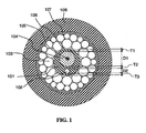
- Fig. 1 shows a preferred embodiment of a cable according to the invention, in particular of the submarine type, wherein a single polymeric buffer tube, comprising a reinforcing element (102) is centrally disposed within a layer of metallic wires (103), according to the cable disclosed in WO 01/09658 .
- said buffer tube is made of a polymeric material comprising a crystalline random copolymer of propylene with at least one C 4 -C 8 ⁇ -olefin, as above defined, preferably with a nucleating agent, as above defined, disbursed therein.
- the buffer tube (101) according to the preferred embodiment of fig. 1 preferably has an outer diameter of from about 2.0 mm to about 6.0 mm, more preferably of from about 2.5 mm to about 4.0 mm.
- the optical fibers can be, for example, multimode fibers, single-mode fibers, such as standard single-mode fibers, dispersion-shifted (DS) fibers, non-zero dispersion (NZD) fibers, or fibers with a large effective area and the like, depending on the application requirements of the cable. Combinations of the above fibers in different sections of the cable can also be used.
- the thickness of the peripheral wall of such buffer tube may vary from a maximum of e.g. about 1.5 mm in correspondence with the portion embedding the strength member, to a minimum of e.g. about 0.2 in correspondence with the diametrically opposed portion. Said thickness will depend, among other variables, from the elastic modulus of the material and from the outer diameter of the tube, in order to protect the fibers during the manufacturing process and the cable installation.
- the thickness (T1) of the buffer tube is of from about 0.2 mm to about 0.6 mm, more preferably of about 0.3 mm.
- the distance (T2), between the tubular passage 104 and the reinforcing element (102), and the distance (T3), between the reinforcing element and the outer surface of the buffer tube will have a similar thickness.
- the reinforcing element (102) can be made of metal (e.g. steel), glass reinforced plastic, aramid fibers reinforced plastic, carbon fibers reinforced plastic or boron fibers reinforced plastic.
- said reinforcing element is a steel wire.
- the diameter D2 of said reinforcing element can be from about 0.3 mm to about 0.8 mm, depending on the dimensions of the buffer tube, preferably of from about 0.4 mm to about 0.65 mm.
- the material employed for such reinforcing element is steel, having a Young modulus of about 180.000-200.000 MPa.
- a buffer tube 101 can be made of a propylene-butene copolymer having an elastic modulus of about 950-1100 (method ISO 178).
- Said tube may have an outer diameter of about 3.5 mm, a thickness T1 of about 0.3 mm, a tubular passage diameter D1 of about 2.1 mm and a steel wire reinforcing element with a diameter D2 of 0.5 mm.
- Thickness T2 and T3 can both be of about 0.3 mm and the total thickness of the portion of peripheral wall embedding said strength member will thus be of about 1.1 mm.
- a number of optical fibers (105) is housed inside the buffer tube (104), said optical fibers being immersed in a jelly-like filler.
- the fibers are housed within the buffer with an excess length of from about 0% to about 0.1%.
- Suitable jelly-like materials for filling the buffer tube (104) typically comprise a base oil, preferably of the synthetic type, particularly those showing good compatibility with olefin polymeric materials (i.e. which do not cause any substantial modification of the physicochemical and mechanical properties of the polymeric material contacted therewith).
- Suitable synthetic oils showing good compatibility with olefin polymeric materials can be selected among silicon oils, polyalphaolefin oils or poly-internal olefin oils.
- the filler composition may contain a thickening/thixotropic agent, such as silanized pyrogenic silica.
- the composition may alternatively or in addition contain a "viscosity improver" such as an elastomeric polymer with a low glass transition point, which by increasing the viscosity of the solution improves its performance as a filling material.
- a viscosity improver such as an elastomeric polymer with a low glass transition point, which by increasing the viscosity of the solution improves its performance as a filling material.
- said compositions may further contain an antioxidant.
- examples of such filler composition are disclosed, for instance; in US 5,455,881 or in EP-A-811,864 .
- Such jelly-like filler should have a viscosity sufficiently low to be easily introduced into the buffer tubes during the manufacturing process and to allow a substantially free relative movement of the fibers inside the tube.
- jelly-like materials suitable for being used as water-blocking filler inside the above buffer tubes are compound K550 ® (Huber Group) or H55 ® (SICPA).
- a layer of metallic wires (103) is then disposed in a helical lay around the buffer tube and presents the characteristics of an arch for withstanding pressure.
- metallic wires of different diameter can advantageously be disposed in a double helical lay according to the so-called Warrington structure.
- the outer surface of the buffer tube can be in contact with the surface of the metallic wires or, preferably, as shown in fig. 1 , a small gap of e.g. about 0.1-0.2 mm is left between said two surfaces.
- the metallic wires are typically made of steel.
- the outer diameter of the double helical lay of metallic wires can be of about 7-9 mm.
- a suitable water-blocking material is discontinuously disposed in the interstices (106) between the outer surface of the buffer tube and the metal wires and in between the metal wires.
- the elastomeric filling material is a water-blocking hydrophobic elastomer, such as a polyurethane-resin.
- the filling of the interstices is preferably accomplished in a discontinuous manner, in such a way that from about 10% to about 80%, preferably from about 20% to about 60% of the total length of the cavity is left free from the filler.
- a discontinuous filling can be accomplished by completely filling a number of longitudinal portions of the cavity with the water-blocking material, each of said filled portions being separated by the subsequent filled portion by a portion substantially free from said filling material.
- the filling material can be disposed in said cavity by filling lengths of from about 10 to about 50 m of said cavity, followed by similar length portions free from said material.
- the cavity can thus be filled, for instance, by about 30 meters with said elastomeric composition, the subsequent 20 meters of the cavity being then left free from the filling material, the further subsequent 30 meters being filled with the filling material, the further subsequent 20 meters being left free, the further subsequent 30 meters being filled again with the elastomeric material and so on.
- a tubular metal sheath (107) (e.g. of copper or aluminum) is then formed around the helical lay of metal wires.
- the thickness of the metal sheath is comprised between about 0.4 mm to about 0.8 mm, depending on the specific electrical resistance required for the cable as described in WO 01/09658 .
- An outer polymeric sheath (108) is then disposed to surround formed metallic sheath.
- Said protective sheath has a thickness of e.g. 2.5-6 mm, preferably of from about 3 to about 5 mm, and can be advantageously made of polyethylene (e.g. high density - HDPE - or medium density - MDPE - polyethylene).
- the cable according to fig. 1 can be typically manufactured in three separate stages, as described in WO 01/09658 herein incorporated by reference as far as manufacturing is concerned.
- First the polymeric buffer tube with the optical fibers immersed into the filling material is manufactured by extrusion and wound on a take-up bobbin.
- the second stage of the manufacturing process comprises disposing the helical lay of the metal wires surrounding the buffer tube, together with the provision of the filling material in the desired interstices, and disposing the metal sheath around the metal wires.
- the third stage (which can also be done on-line after the second stage), comprises the extrusion of the outer polymeric protective sheath.
- the Applicant has found that the use of the above mentioned C 4 -C 8 ⁇ -olefin containing propylene copolymer results in an improved control of the process parameters and of the geometrical features of the buffer tube during the manufacturing process, as well as in an improved transparence of the final product.
- Fig. 2 shows an alternative embodiment of a cable according to the invention, in particular of a terrestrial cable.
- the cable shown in Figure 2 has in its radially innermost position a reinforcing element(201), typically made from glass-fibre reinforced plastic, coated with a layer (202) of polymeric material, for instance a polyolefin.
- the cable has one or more polymeric buffer tubes (203) according to the invention, said tubes comprising a number of optical fibers (204), which are embedded in a filling material (205).
- the optical fiber can be, for example, multimode fibers, single-mode fibers, such as standard single-mode fibers, dispersion-shifted (DS) fibers, non-zero dispersion (NZD) fibers, or fibers with a large effective area and the like, depending on the application requirements of the cable. Combinations of the above fibers in different sections and/or tubes of the cable can also be used.
- filling compositions suitable for being used as water-blocking filler inside the above buffer tubes are those mentioned previously with respect to the buffer tube of fig. 1 .
- the number of buffer tubes (203) present in the cable (which may also be arranged on several superposed layers) and the dimensions of these tubular elements depend on the intended capacity of the cable, as well as on the conditions under which this cable will be used. For example, six, eight or more tubular elements, arranged in one or more layers (for example up to 48 tubes), can be disposed around the central element.
- the buffer tubes (203) are disposed in a helical lay around the central member, said lay being either a continuous helix or preferably an open helix obtained by alternate (S-Z) stranding of the tube.
- one or more tubes may be replaced by one or more rods, in order to preserve the symmetry of the helical configuration in case the fiber count is lower than the full fiber count.
- the central element can be replaced by a further tubular element as those previously mentioned, apt to contain optical fibers.
- the interstices (206) among the buffer tubes can also be filled with a filling compositions such as those previously mentioned, said compositions having preferably a higher viscosity.
- a water swellable powder i.e. a compound having the property of gelling/swelling upon water absorption
- sodium polyacrylate or polymethacrylate can be advantageously added to the jelly-like composition as disclosed, for example, in US patent no. 5,715,343 .
- Stranded tubes are generally bound together with a polymeric yarn or tape (not shown), e.g. a polyester or polypropylene yarn, in order to held them firmly in their helical configuration during manufacturing processes.
- a polymeric yarn or tape e.g. a polyester or polypropylene yarn
- a further polymeric tape (not shown), for instance of polyester (e.g. Mylar ® ), can be optionally wound with overlapping around the stranded buffer tubes in order to allow an effective containment of the interstitial water-blocking filler.
- a water-blocking (or water swellable) tape (207) can be wound around the whole structure.
- Such water-blocking tapes generally comprise a polymeric base tape on the surface of which a superabsorbent swellable material (e.g. polyacrylate or polymethylmethacrylate) in the form of powder is chemically or thermally fixed. Examples of suitable water-swellable tapes are those commercialized by Freudenberg under the trademark Viledon ® , e.g. Viledon ® K3415, K3416, K3417 or K3516.
- the stranded tubes can then be wrapped by a reinforcing layer (208), e.g. made of aramidic yarns (Kevlar ® ) or glass thread, optionally containing two sheath cutting threads (209) disposed longitudinally with respect to the cable.
- a reinforcing layer e.g. made of aramidic yarns (Kevlar ® ) or glass thread, optionally containing two sheath cutting threads (209) disposed longitudinally with respect to the cable.
- An outer polymeric layer e.g. of polyolefin (for instance as above defined for the component according to the present invention) is then disposed to surround the cable structure.
- a metal tape (not shown), preferably corrugated, can be disposed between the outer sheath (210) and the reinforcing layer.
- any optical cable component as herein defined can be made of and manufactured with the polymeric material as above defined, which can be therefore used for cable components such as slotted cores containing optical fibers, polymeric tapes, e.g. for wrapping a plurality of buffer tubes, or jackets disposed to surround inner radial portions (e.g. a group of buffer tubes) of an optical cable.
- Finapro 4660G - a crystalline "heterophasic" propylene/ethylene copolymer, produced by Fina Chemicals, consisting of about 85% linear polypropylene and 15% ethylene-propylene rubber. Melt Index (MI) measured at 230°C and 2.16 kg is 3.5 g/10 min.
- Clyrell 831 RCXP - a crystalline propylene-butene random copolymer comprising about 5.2% butene, produced by Montell, MI 1.8 g/10 min at 230°C and 2.16 kg.
- compositions of the examples 2 to 6 were obtained by mixing the polymer material with the powdered nucleating agent in a 20 mm double-screw Brabender at a temperature of about 190°C to complete homogenization.
- the material left the double-screw mixer in the form of granules.
- compositions of Examples 1-6 were then used to feed a 30 mm strainer and obtain an extruded tube with an outer diameter of 3.5 mm, an inner diameter of 2.0 mm and a minimum and maximum thickness of 0.2 and 1.1 mm, respectively, according to the buffer tube exemplified with reference to fig. 1 .
- the melt temperature at the head outlet was 210°C whereas it was about 20°C lower in the case of examples 4 to 6.
- a Shape Index which is an integer number in a scale from 1 to 10 corresponding to the % ovalization of the tube (as reported in the following table 2)
- mm Hg depression
- the following table shows the correlation between the shape index value and the observed percentage of ovalization of the tube, wherein the percentage of ovalization is expressed as percentage difference between the maximum and the minimum measured outer diameter of the extruded tube.
- Table 2 Shape index (SI) Percentage ovalization (po) 10 po ⁇ 0.5 9 0.5 ⁇ po ⁇ 1.75 8 1.75 ⁇ po ⁇ 3.0 7 3.0 ⁇ po ⁇ 4..25 6 4.25 ⁇ po ⁇ 5.5 5 5.5 ⁇ po ⁇ 6.75 4 6.75 ⁇ po ⁇ 8.0 3 8.0 ⁇ po ⁇ 9.25 2 9.25 ⁇ po ⁇ 10.5 1 po > 10.5
- the standard propylene-ethylene copolymer Finapro 4660G material when added with a sorbitol derivative as nucleating agent (Ex. 3), shows a shape index of 9 with an applied depression of 200 mmHg.
- the buffer tubes of the invention comprising the above defined polymer material, when added with the same nucleating agent (Ex. 5 and 6), show instead a shape index of 10 with an even reduced applied depression of 100 and 150 mmHg respectively.
- the polymer material suitable for the invention shows a very good transparency adversely from heterophase propylene-ethylene copolymers and regardless of the added nucleating agent. Transparency was determined by measuring the transmittance of a ray of light in the visible spectrum (400-700 nm) through a 1 mm thick material sample using an UV visible spectrophotometer Varian, mod. CARY3E.
- the melting points were measured by Mettler DSC instrumentation (second melting value) with a scanning rate of 10°C/min (instrument head type DSC 30, microprocessor type PC 11, Mettler software Graphware TA72AT.1); the relevant values evidently show how the compositions of the invention allow to use lower process temperatures.
Landscapes
- Physics & Mathematics (AREA)
- Chemical & Material Sciences (AREA)
- General Physics & Mathematics (AREA)
- Optics & Photonics (AREA)
- Health & Medical Sciences (AREA)
- Chemical Kinetics & Catalysis (AREA)
- Medicinal Chemistry (AREA)
- Polymers & Plastics (AREA)
- Organic Chemistry (AREA)
- Compositions Of Macromolecular Compounds (AREA)
- Laying Of Electric Cables Or Lines Outside (AREA)
- Addition Polymer Or Copolymer, Post-Treatments, Or Chemical Modifications (AREA)
Abstract
Description
- The invention relates to an optical fiber cable comprising a component of polymeric material having, in particular, an improved dimensional stability and to said optical fiber cable component. More in particular, said cable component is preferably in the form of a tube of polymeric material comprising at least one optical fiber housed therein.
- As mentioned in
US patent no. 5,911,023 , in designing the cable structure, it is important to ensure that process or construction induced stresses related to cable production do not interfere with optical fiber performance. For extruded components, such as buffer tubes containing optical fibers, poor flexibility, compression-tension resistance and thermal expansion properties may result in an overall reduced efficiency of the optical fibers and residual stress in the finished product. - According to the above cited patent, while fiber optic buffer tubes have been primarily made from engineering resins (such as polybutylenterephtalate (PBT), polycarbonate, polyamides), the use of polyolefin buffer tubes have become increasingly attractive.
- For instance,
US 5,574,816 discloses a buffer tube for an optical fiber cable made from a propylene-ethylene copolymer resin having nucleating agents and filler materials disbursed therein. The nucleating agents and filler materials improve compression-tension resistance and thermal expansion properties of the polypropylene-polyethylene buffer tube; further, a low shrinkage, without negatively affecting flexibility and cost, is observed. Examples of materials suitable for realising the buffer tubes are Stamylan 83E10N, a polypropylene resin produced by DSM Engineering Plastics of Geleen, The Netherlands, having approximately 11 weight percent polyethylene and 0.4 weight percent talc nucleating agent. - The above cited
US 5,911,023 discloses optical fiber components, such as a buffer tube, a polymeric jacket or a slotted core, made of a thermoplastic polyolefin, preferably a propylene or ethylene homopolymer or a propylene-ethylene copolymer, characterized by a Melt Flow Index (MFI) higher than 3 and wherein a nucleating agent is disbursed therein, which result in substantial improvements in buffer tube crystallinity and crystallization rates, as well as reduced post extrusion shrinkage and improved crush resistance, gel compatibility and fiber length control. -
US 5,751,880 relates to an optical unit for an optical fiber telecommunications cable, the unit comprising a tube of plastics material, preferably polyethylene, polypropylene or polyvinyl chloride, having a modulus of elasticity less than 1500 MPa at 20°C and a stress/elongation curve without a yield point. The proposed materials provide flexible and elastic tubes for the optical fiber unit, thereby making handling thereof easier. Because of its flexibility, the optical unit has greatly reduced "memory" thereby facilitating splicing operations on stranded loose tube structure cables. -
EP-A-1,024,382 discloses a telecommunications cable element having a transmission element disposed in a buffer tube made from thermoplastic polyolefin elastomeric buffer material, preferably a propylene-ethylene copolymer, having a modulus of elasticity below about 500 MPa at room temperature and below about 1500 MPa at -40°C. Preferably, the polyolefin has an elongation at break below about 500% and an MFI above about 3. Flexibility of the elastomeric material is maintained over a wide range of temperature; further, its compatibility with low cost, thixotropic, water-blocking gel filling materials is observed. - International patent application publ. No.
WO 01/09658 - Documents
WO97/19991 EP 0339804 , andUS 6,121,401 disclose extrudable materials comprising a C4 - C8 α-olefin. - The Applicant has however observed that the polyolefin materials used heretofore for manufacturing the optical buffer tubes may cause undesirable variations in the shape of the extruded buffer tubes. In particular, it has been observed that it may result difficult to maintain the desired substantially circular shape of the extruded buffer tube. After extrusion, the buffer tube is in fact subjected to a cooling step, typically by passing the tube along a water-cooling trough. As observed by the Applicant, a possible non-homogeneous (or differential) cooling of the tube (e.g. because of a variation in the thickness of the tube walls or because of the different temperatures between the polymeric melt forming the tube and the filling material and/or optical fibers contained therein), may determine an unwanted and uncontrollable variation of the desired shape of the tube. While this shape variation may be caused on any extruded component of an optical fiber cable which is subjected to a differential cooling, it becomes much more apparent when said element is a buffer tube, particularly having a non-symmetric design, for instance a buffer tube having a single strength member embedded into the peripheral wall of the buffer tube, such as the one disclosed in the above cited
WO 01/09658 - The Applicant has now found that by selecting a suitable polyolefin material, in particular a copolymer of polypropylene with a C4-C8 α-olefin, it is possible to avoid or at least substantially reduce the above shape variations of the extruded component, in particular of a buffer tube containing optical fibers.
- As used herein and for the purposes of the present invention, the term "optical fiber cable component" or "(extruded) component of an optical fiber cable" is referred to any conventional component which may advantageously be manufactured by using a polymeric material as above defined. Preferably, these components have at least one reinforcing element or strength member embedded therein. Preferably, these components are apt to receive and house at least one optical fiber therein. The term may thus comprise polymeric outer sheaths of optical cables or any intermediate polymeric sheath disposed to surround an inner structure of an optical fiber cable, preferably those wherein at least one reinforcing longitudinal element (such as a steel wire or a fiber glass rod) is disposed therein. Preferably, said term is referred to those components designed for housing optical fibers therein, such as a so-called "slotted core" or more preferably a buffer tube. Preferably said buffer tube is centrally disposed within a cable structure and more preferably it comprises at least one longitudinal reinforcing element embedded into its peripheral wall.
- As observed by the Applicant, the above copolymer has the further advantages of being extrudable at relatively lower temperatures and of resulting in a component which has improved transparency with respect to the conventional polyolefins employed in the art.
- A lower extrusion temperature of the material allows, for instance, a reduced shrinkage of a jelly-like filler disposed within a tube made from said material, with consequent improved filling of said tube. On the other side, an improved transparency of a component, in particular of a buffer tube made from said material, may allow an easier visual detection of the different optical fibers housed therein as well as an easier visual determination of the amount of filling material contained therein.
- According to a first aspect, the present invention relates to an optical fiber cable comprising a cable component wherein the cable component is made of a polymeric material comprising a crystalline random copolymer of propylene with at least one C4-C8 α-olefin.
- In particular, said polymeric material is a thermoplastic material. Preferably, said cable component is substantially made of said copolymer.
- According to a preferred embodiment, said cable component is a buffer tube defined by a peripheral polymeric wall and containing at least one optical fiber housed therein. Preferably, a longitudinal reinforcing element is embedded in said peripheral wall of said buffer tube.
- According to another aspect, the present invention relates to an optical fiber cable component made of a polymeric material comprising a crystalline random copolymer of propylene with at least one C4-C8 α-olefin.
- In the present specification, the term "C4-C8 α-olefin" means an olefin of formula CH2=CH-R, where R is a linear or branched alkyl containing 2 to 6 carbon atoms. The α-olefin can be selected for example from 1-butene, 1-pentene, 3-methyl-1-butene, 4-methyl-1-pentene, 1-hexene, 3,4-dimethyl-1-butene, 1-octene, and the like or a mixture thereof. 1-butene is particularly preferred for implementing the invention.
- Preferably, the copolymer contains from about 1% to about 12%, more preferably from about 4% to about 10% by weight of C4-C8 α-olefin, with respect to the total weight of the copolymer.
- According to a preferred embodiment a nucleating agent is disbursed into the polymeric material.
- The nucleating agent is preferably in the range of 0.05% to 1%, particularly 0.1% to 0.5% by weight, with respect to the total weight of the copolymer.
- Preferably, said nucleating agents are inorganic materials, D-sorbitol derivatives, salts of aliphatic monobasic or dibasic acids, aralkyl acids, or alkali metal or aluminum salts of aromatic or alicyclic carboxylic acids, talc, or a mixture thereof and the like. D-sorbitol derivatives are preferred.
- Extruded optical fiber components, in particular buffer tubes made of the above defined polymeric material, preferably in combination with the above nucleating agents, revealed advantageous dimensional stability properties. The Applicant indeed observed that a buffer tube according to the invention shows an improved dimensional stability, in particular upon cooling after extrusion. Dimensional stability of the tube means that the tube maintains its substantially circular shape, in particular when it is cooled after being extruded.
- As explained in detail in the following of the description, for helping the tube to maintain its circular shape, the tube is preferably cooled, in particular into a water bath under negative pressure. The higher the vacuum to be applied, the higher the tendency to deformation of the tube. Preferred materials are thus those which allow to extrude a tube of substantially circular shape by applying the lowest possible vacuum.
- A cable component comprising a copolymer as above defined further shows a transparency higher than those ones made of the conventional polyolefin materials, the transmittance of the polymeric material forming said component being of above 70%, preferably of above 80%, measured on a 1 mm thickness layer of said material.
- A further advantage obtainable when manufacturing an optical fiber cable according to the invention stands in the possibility to adopt process temperatures lower than the ones used with the conventional polyolefin materials.
- The peculiar characteristics of the optical fiber cable component of the invention make it suitable for both terrestrial and undersea uses. Particularly, wishing to realise an undersea optical fiber cable comprising a central buffer tube, it is preferred to realise a cable with a buffer tube having a reinforcing element such as the buffer tube described in the above cited
WO 01/09658 - The buffer tube disclosed in the preferred embodiment of said
WO 01/09658 - Possible deformations of said tube upon cooling after extrusion can thus be avoided by using a polymeric material according to the present invention for manufacturing the above buffer tube.
- For a better comprehension of the invention, the following drawings are given:
-
Fig. 1 is a cross-sectional view of a cable according to the invention; -
Fig. 2 is a cross-sectional view of an alternative embodiment of a cable according to the invention. - As mentioned before, the present invention relates to an optical fiber cable component and to an optical fiber cable comprising said component, wherein said component is made of a polymeric material comprising a crystalline random copolymer of propylene with at least one C4-C8 α-olefin, as above defined, preferably with a nucleating agent, as above defined, disbursed therein.
- The α-olefin of formula CH2=CH-R, where R is a linear or branched alkyl containing 2 to 6 carbon atoms, can be selected for example from 1-butene, 1-pentene, 3-methyl-1-butene, 4-methyl-1-pentene, 1-hexene, 3,4-dimethyl-1-butene, 1-octene, and the like and the combinations thereof, 1-butene being particularly preferred.
- Preferably, the copolymer contains from about 1% to about 12%, more preferably from about 4% to about 10% by weight of the C4-C8 α-olefin, with respect to the total weight of the copolymer.
- Said copolymer preferably has a melting point of from about 140°C to about 156°C; preferably, its crystallization point is from about 90°C to 120°C, both measured by DSC (Differential Scanning Calorimetry) at a temperature variation of 10°C/min.
- The content of fractions insoluble in xylene at 25°C is preferably higher that about 93%, more preferably higher than about 95%.
- Examples of commercial copolymers suitable for manufacturing an optical fiber component according to the present invention are propylene-butene random copolymers sold by Montell under the tradenames Clyrell® or Moplen®, in particular Clyrell 721 RCXP, Clyrell 831 RCXP or Moplen Ultra 925 RCXP.
- Preferably, said copolymer has a Melt Flow Index (MFI) in the range from 1 to 15, more preferably from 1 to 10 g/10 min, measured at 190°C (ASTM 1238).
- The above polymeric material comprised into said component should have a sufficiently high flexural modulus (method ISO 178) in order to impart the desired protection to the optical fibers housed therein. Preferably, said modulus is of at least about 500 MPa, preferably at least 800 MPa or higher. Said modulus is however preferably not too high, e.g. below about 1500 MPa, in order to avoid an excessive stiffness of the cable component.
- Preferably, said random copolymer of propylene containing at least one C4-C8 α-olefin is used in the pure state. The polymeric portion of a buffer tube according to the invention can advantageously be made entirely from said propylene copolymer.
- Alternatively, the random copolymer of propylene containing at least one C4-C8 α-olefin can be used in admixture with at least a second olefin polymer, such as propylene homopolymer or crystalline propylene copolymer containing from 1% to 3% by weight of ethylene. The amount of said second olefin polymer, when present, can be in the range of from about 10% to about 40%, preferably from about 10% to about 30%, with respect to the total weight of the copolymer of propylene containing at least one C4-C8 α-olefin.
- As above mentioned, a nucleating agent, particularly in the range of 0.05% to 1%, more particularly 0.1% to 0.5% by weight, with respect to the total weight of the copolymer, is preferably disbursed into the polymeric material in order to further increase the dimensional stability of the optical fiber cable component. Whichever nucleating agent known in the field can be used for realising the cable of the invention. Examples of suitable nucleating agents are inorganic materials, D-sorbitol derivatives, salts of aliphatic monobasic or dibasic acids, aralkyl acids, or alkali metal or aluminum salts of aromatic or alicyclic carboxylic acids, talc or a mixture thereof, and the like. D-sorbitol derivatives are preferred, which allow to obtain increased transparency of the product. Particularly preferred is a D-sorbitol derivative of the following formula:


- As mentioned before, the optical fiber cable component according to the invention is preferably a buffer tube containing at least one optical fiber housed therein.
-
Fig. 1 shows a preferred embodiment of a cable according to the invention, in particular of the submarine type, wherein a single polymeric buffer tube, comprising a reinforcing element (102) is centrally disposed within a layer of metallic wires (103), according to the cable disclosed inWO 01/09658 - According to the invention, said buffer tube is made of a polymeric material comprising a crystalline random copolymer of propylene with at least one C4-C8 α-olefin, as above defined, preferably with a nucleating agent, as above defined, disbursed therein.
- The buffer tube (101) according to the preferred embodiment of
fig. 1 preferably has an outer diameter of from about 2.0 mm to about 6.0 mm, more preferably of from about 2.5 mm to about 4.0 mm. The tubular passage (104), wherein optical fibers (105) are housed, preferably has a diameter (D1) of from about 1.0 mm to about 4.5 mm, more preferably of about 1.2 mm to about 3.0 mm. - The optical fibers can be, for example, multimode fibers, single-mode fibers, such as standard single-mode fibers, dispersion-shifted (DS) fibers, non-zero dispersion (NZD) fibers, or fibers with a large effective area and the like, depending on the application requirements of the cable. Combinations of the above fibers in different sections of the cable can also be used.
- The thickness of the peripheral wall of such buffer tube may vary from a maximum of e.g. about 1.5 mm in correspondence with the portion embedding the strength member, to a minimum of e.g. about 0.2 in correspondence with the diametrically opposed portion. Said thickness will depend, among other variables, from the elastic modulus of the material and from the outer diameter of the tube, in order to protect the fibers during the manufacturing process and the cable installation. Preferably, the thickness (T1) of the buffer tube is of from about 0.2 mm to about 0.6 mm, more preferably of about 0.3 mm. Preferably, also the distance (T2), between the
tubular passage 104 and the reinforcing element (102), and the distance (T3), between the reinforcing element and the outer surface of the buffer tube, will have a similar thickness. - The reinforcing element (102), can be made of metal (e.g. steel), glass reinforced plastic, aramid fibers reinforced plastic, carbon fibers reinforced plastic or boron fibers reinforced plastic. Preferably said reinforcing element is a steel wire. The diameter D2 of said reinforcing element can be from about 0.3 mm to about 0.8 mm, depending on the dimensions of the buffer tube, preferably of from about 0.4 mm to about 0.65 mm. According to a preferred embodiment, the material employed for such reinforcing element is steel, having a Young modulus of about 180.000-200.000 MPa.
- For instance, with reference to
fig. 1 , abuffer tube 101 can be made of a propylene-butene copolymer having an elastic modulus of about 950-1100 (method ISO 178). Said tube may have an outer diameter of about 3.5 mm, a thickness T1 of about 0.3 mm, a tubular passage diameter D1 of about 2.1 mm and a steel wire reinforcing element with a diameter D2 of 0.5 mm. Thickness T2 and T3 can both be of about 0.3 mm and the total thickness of the portion of peripheral wall embedding said strength member will thus be of about 1.1 mm. - A number of optical fibers (105) is housed inside the buffer tube (104), said optical fibers being immersed in a jelly-like filler. The fibers are housed within the buffer with an excess length of from about 0% to about 0.1%.
- Suitable jelly-like materials for filling the buffer tube (104) typically comprise a base oil, preferably of the synthetic type, particularly those showing good compatibility with olefin polymeric materials (i.e. which do not cause any substantial modification of the physicochemical and mechanical properties of the polymeric material contacted therewith). Suitable synthetic oils showing good compatibility with olefin polymeric materials can be selected among silicon oils, polyalphaolefin oils or poly-internal olefin oils. The filler composition may contain a thickening/thixotropic agent, such as silanized pyrogenic silica. The composition may alternatively or in addition contain a "viscosity improver" such as an elastomeric polymer with a low glass transition point, which by increasing the viscosity of the solution improves its performance as a filling material. Typically, said compositions may further contain an antioxidant. Examples of such filler composition are disclosed, for instance; in
US 5,455,881 or inEP-A-811,864 - A layer of metallic wires (103) is then disposed in a helical lay around the buffer tube and presents the characteristics of an arch for withstanding pressure. In particular, as shown in
fig. 1 , metallic wires of different diameter can advantageously be disposed in a double helical lay according to the so-called Warrington structure. The outer surface of the buffer tube can be in contact with the surface of the metallic wires or, preferably, as shown infig. 1 , a small gap of e.g. about 0.1-0.2 mm is left between said two surfaces. The metallic wires are typically made of steel. The outer diameter of the double helical lay of metallic wires can be of about 7-9 mm. - A suitable water-blocking material is discontinuously disposed in the interstices (106) between the outer surface of the buffer tube and the metal wires and in between the metal wires. Preferably, the elastomeric filling material is a water-blocking hydrophobic elastomer, such as a polyurethane-resin.
- The filling of the interstices is preferably accomplished in a discontinuous manner, in such a way that from about 10% to about 80%, preferably from about 20% to about 60% of the total length of the cavity is left free from the filler. For instance, a discontinuous filling can be accomplished by completely filling a number of longitudinal portions of the cavity with the water-blocking material, each of said filled portions being separated by the subsequent filled portion by a portion substantially free from said filling material. For instance the filling material can be disposed in said cavity by filling lengths of from about 10 to about 50 m of said cavity, followed by similar length portions free from said material.
- An example of commercially available water-blocking material is "D ENCAPSULANT" (CasChem).
- The cavity can thus be filled, for instance, by about 30 meters with said elastomeric composition, the subsequent 20 meters of the cavity being then left free from the filling material, the further subsequent 30 meters being filled with the filling material, the further subsequent 20 meters being left free, the further subsequent 30 meters being filled again with the elastomeric material and so on.
- A tubular metal sheath (107) (e.g. of copper or aluminum) is then formed around the helical lay of metal wires. The thickness of the metal sheath is comprised between about 0.4 mm to about 0.8 mm, depending on the specific electrical resistance required for the cable as described in
WO 01/09658 - The cable according to
fig. 1 can be typically manufactured in three separate stages, as described inWO 01/09658 - According to the invention, the Applicant has found that the use of the above mentioned C4-C8 α-olefin containing propylene copolymer results in an improved control of the process parameters and of the geometrical features of the buffer tube during the manufacturing process, as well as in an improved transparence of the final product.
-
Fig. 2 shows an alternative embodiment of a cable according to the invention, in particular of a terrestrial cable. The cable shown inFigure 2 has in its radially innermost position a reinforcing element(201), typically made from glass-fibre reinforced plastic, coated with a layer (202) of polymeric material, for instance a polyolefin. The cable has one or more polymeric buffer tubes (203) according to the invention, said tubes comprising a number of optical fibers (204), which are embedded in a filling material (205). - The optical fiber can be, for example, multimode fibers, single-mode fibers, such as standard single-mode fibers, dispersion-shifted (DS) fibers, non-zero dispersion (NZD) fibers, or fibers with a large effective area and the like, depending on the application requirements of the cable. Combinations of the above fibers in different sections and/or tubes of the cable can also be used.
- Examples of filling compositions suitable for being used as water-blocking filler inside the above buffer tubes are those mentioned previously with respect to the buffer tube of
fig. 1 . - The number of buffer tubes (203) present in the cable (which may also be arranged on several superposed layers) and the dimensions of these tubular elements depend on the intended capacity of the cable, as well as on the conditions under which this cable will be used. For example, six, eight or more tubular elements, arranged in one or more layers (for example up to 48 tubes), can be disposed around the central element.
- The buffer tubes (203) are disposed in a helical lay around the central member, said lay being either a continuous helix or preferably an open helix obtained by alternate (S-Z) stranding of the tube. If desired, one or more tubes may be replaced by one or more rods, in order to preserve the symmetry of the helical configuration in case the fiber count is lower than the full fiber count. Alternatively, the central element can be replaced by a further tubular element as those previously mentioned, apt to contain optical fibers.
- The interstices (206) among the buffer tubes can also be filled with a filling compositions such as those previously mentioned, said compositions having preferably a higher viscosity. For further improving the water blocking properties of said filling material, a water swellable powder (i.e. a compound having the property of gelling/swelling upon water absorption), such as sodium polyacrylate or polymethacrylate, can be advantageously added to the jelly-like composition as disclosed, for example, in
US patent no. 5,715,343 . - Stranded tubes are generally bound together with a polymeric yarn or tape (not shown), e.g. a polyester or polypropylene yarn, in order to held them firmly in their helical configuration during manufacturing processes.
- A further polymeric tape (not shown), for instance of polyester (e.g. Mylar®), can be optionally wound with overlapping around the stranded buffer tubes in order to allow an effective containment of the interstitial water-blocking filler. A water-blocking (or water swellable) tape (207) can be wound around the whole structure. Such water-blocking tapes generally comprise a polymeric base tape on the surface of which a superabsorbent swellable material (e.g. polyacrylate or polymethylmethacrylate) in the form of powder is chemically or thermally fixed. Examples of suitable water-swellable tapes are those commercialized by Freudenberg under the trademark Viledon®, e.g. Viledon® K3415, K3416, K3417 or K3516.
- The stranded tubes can then be wrapped by a reinforcing layer (208), e.g. made of aramidic yarns (Kevlar®) or glass thread, optionally containing two sheath cutting threads (209) disposed longitudinally with respect to the cable. An outer polymeric layer, e.g. of polyolefin (for instance as above defined for the component according to the present invention), is then disposed to surround the cable structure. Optionally, a metal tape (not shown), preferably corrugated, can be disposed between the outer sheath (210) and the reinforcing layer.
- Although a cable component according to the invention has been illustrated with specific reference to the buffer tubes of the cable of
figs. 1 and2 , it will be understood that any optical cable component as herein defined can be made of and manufactured with the polymeric material as above defined, which can be therefore used for cable components such as slotted cores containing optical fibers, polymeric tapes, e.g. for wrapping a plurality of buffer tubes, or jackets disposed to surround inner radial portions (e.g. a group of buffer tubes) of an optical cable. - The following examples illustrate the invention more in detail.
- Six different compositions, made of either a polymeric material alone or also including a nucleating agent, were prepared and are illustrated in the following table where all amounts are expressed as weight phr (per hundred of resin) on the total weight of the composition.
Table 1 E. 1* E. 2* E. 3* E. 4 E. 5 E. 6 Finapro 4660G 100 100 100 Clyrell 831 100 100 RCXP Moplen Ultra 100 925 RCXP Talc 1N-M20 0.3 0.3 Millad 3988 0.3 0.3 0.3 E. = Example; * = comparison - Finapro 4660G - a crystalline "heterophasic" propylene/ethylene copolymer, produced by Fina Chemicals, consisting of about 85% linear polypropylene and 15% ethylene-propylene rubber. Melt Index (MI) measured at 230°C and 2.16 kg is 3.5 g/10 min.
- Clyrell 831 RCXP - a crystalline propylene-butene random copolymer comprising about 5.2% butene, produced by Montell, MI = 1.8 g/10 min at 230°C and 2.16 kg.
- Moplen Ultra 925 RCXP - a crystalline propylene-butene random copolymer, comprising about 7.1% butene and an antigas-fading phenolic stabilizer, produced by Montell, MI = 10 g/10 min at 230°C and 2.16 kg.
- Talc 1N-M20 from Val Chisone - a talc showing 98% of its particles having dimensions lower than 20 µm, commercially available from Luzenac.
- Millad 3988 - 3,4-di(methylbenzylidene) sorbitol; a fully organic nucleating agent produced by Milliken Chemicals.
- The compositions of the examples 2 to 6 were obtained by mixing the polymer material with the powdered nucleating agent in a 20 mm double-screw Brabender at a temperature of about 190°C to complete homogenization. The material left the double-screw mixer in the form of granules.
- The compositions of Examples 1-6 were then used to feed a 30 mm strainer and obtain an extruded tube with an outer diameter of 3.5 mm, an inner diameter of 2.0 mm and a minimum and maximum thickness of 0.2 and 1.1 mm, respectively, according to the buffer tube exemplified with reference to
fig. 1 . In comparative examples 1-3, the melt temperature at the head outlet was 210°C whereas it was about 20°C lower in the case of examples 4 to 6. - The ability to maintain the shape was measured and is expressed by two parameters: a Shape Index, which is an integer number in a scale from 1 to 10 corresponding to the % ovalization of the tube (as reported in the following table 2), and the depression (mm Hg) of the applied vacuum necessary to maintain the correct shape.
- The higher the index is, the better the buffer tube geometry, whereas the higher the depression is, the worse the polyolefin material performance.
- The following table shows the correlation between the shape index value and the observed percentage of ovalization of the tube, wherein the percentage of ovalization is expressed as percentage difference between the maximum and the minimum measured outer diameter of the extruded tube.
Table 2 Shape index (SI) Percentage ovalization (po) 10 po ≤ 0.5 9 0.5 < po ≤ 1.75 8 1.75 < po ≤ 3.0 7 3.0 < po ≤ 4..25 6 4.25 < po ≤ 5.5 5 5.5 < po ≤ 6.75 4 6.75 < po ≤ 8.0 3 8.0 < po ≤ 9.25 2 9.25 < po ≤ 10.5 1 po > 10.5 - The results of the extrusion tests and the measures subsequently carried out are reported in the following table 3.
Table 3 SI/D T Mp E. 1* 3/500 53-63 165 E. 2* 8/200 49-66 165 E. 3* 9/200 52-65 165 E. 4 9/200 80-87 151 E. 5 10/100 80-87 151 E. 6 10/150 76-86 148 SI/D = Shape Index (arbitrary units)/Depression (mmHg); E. = Example; * = comparison; T = transparency (transmittance, %); mp = melting point (°C). - It is evident from the above table that a standard propylene-ethylene copolymer as Finapro 4660G without the addition of a nucleating agent, is unsuitable since it shows a shape index of 3 with an applied depression 500 mmHg. The same material when added with talc as nucleating agent (ex. 2) shows a shape index of 8 with an applied depression of 200 mmHg. On the contrary, the buffer tube made from a material according to the invention, when added with talc (Ex. 4) shows a shape index of 9 with the same applied depression.
- Finally, the standard propylene-ethylene copolymer Finapro 4660G material, when added with a sorbitol derivative as nucleating agent (Ex. 3), shows a shape index of 9 with an applied depression of 200 mmHg. The buffer tubes of the invention, comprising the above defined polymer material, when added with the same nucleating agent (Ex. 5 and 6), show instead a shape index of 10 with an even reduced applied depression of 100 and 150 mmHg respectively.
- An improvement can thus be evidently observed by using the polypropylene copolymer above defined as material suitable for the buffer tubes of the invention, which guarantees the obtainment and keeping of the desired shape.
- Further, the polymer material suitable for the invention shows a very good transparency adversely from heterophase propylene-ethylene copolymers and regardless of the added nucleating agent. Transparency was determined by measuring the transmittance of a ray of light in the visible spectrum (400-700 nm) through a 1 mm thick material sample using an UV visible spectrophotometer Varian, mod. CARY3E.
- The melting points were measured by Mettler DSC instrumentation (second melting value) with a scanning rate of 10°C/min (instrument head type DSC 30, microprocessor type PC 11, Mettler software Graphware TA72AT.1); the relevant values evidently show how the compositions of the invention allow to use lower process temperatures.
Claims (30)
- Optical fiber cable comprising a cable component apt to receive and house at least one optical fiber, wherein the cable component is made of a polymeric material comprising a crystalline random copolymer of propylene with at least one C4-C8 α-olefin and wherein the copolymer contains from about from about 4% to about 10% weight percent of the C4-C8 α-olefin, with respect to the total weight of the copolymer.
- An optical cable according to claim 1, wherein the cable component is a buffer tube defined by a peripheral polymeric wall and containing at least one optical fiber housed therein.
- An optical cable according to claim 2, wherein a longitudinal reinforcing element is embedded in the peripheral wall of the buffer tube.
- An optical cable according to any of the previous claims, wherein the cable component is substantially made of the copolymer.
- An optical fiber cable according to any of the previous claims, wherein the C4-C8 α-olefin is an olefin of formula CH2=CH-R, where R is a linear or branched alkyl containing 2 to 6 carbon atoms.
- An optical fiber cable according to any of the previous claims, wherein the c4-C8 α-olefin is selected from 1-butene, 1-pentene, 3-methyl-1-butene, 4-methyl-1-pentene, 1-hexene, 3,4-dimethyl-1-butene, 1-octene or a mixture thereof.
- An optical fiber cable according to any of the previous claims, wherein the C4-C8 α-olefin is 1-butene.
- An optical fiber cable according to any of the previous claims, wherein the copolymer has a melting point of from about 140°C to about 156°C.
- An optical fiber cable according to any of the previous claims, wherein the copolymer has a crystallization point from about 90°C to 120°C.
- An optical fiber cable according to any of the previous claims, wherein the copolymer has a content of fractions insoluble in xylene at 25°C higher that about 93%.
- An optical fiber cable according the previous claim, wherein the copolymer has a content of fractions insoluble in xylene at 25°C higher that about 95%.
- An optical fiber cable according to any of the previous claims, wherein the copolymer has a Melt Flow Index (MFI) in the range from 1 to 15 g/10 min, measured at 190°C (ASTM 1238).
- An optical fiber cable according to any of the previous claims, wherein the copolymer has a Melt Flow Index (MFI) in the range from 1 to 10 g/10 min, measured at 190°C (ASTM 1238).
- An optical fiber cable according to any of the previous claims, wherein the polymeric material has a flexural modulus (method ISO 178) of at least about 500 MPa.
- An optical fiber cable according to any of the previous claims, wherein the polymeric material has a flexural modulus (method ISO 178) in the range of about 800 to 1500 MPa.
- An optical fiber cable according to any of the previous claims, wherein the transmittance of the polymeric material is above 70%.
- An optical fiber cable according to any of the previous claims, wherein the transmittance of the polymeric material is above 80%.
- An optical fiber cable according to any of the previous claims, wherein the copolymer is in admixture with at least a second olefin polymer.
- An optical fiber cable according the previous claim, wherein the second olefin polymer is selected from a propylene homopolymer or a crystalline propylene copolymer containing from 1% to 3% by weight of ethylene.
- An optical fiber cable according to claim 18 or 19, wherein the amount of the second olefin polymer is in the range of from about 10% to about 40%, with respect to the total weight of the copolymer of propylene containing at least one C4-C8 α-olefin.
- An optical fiber cable according to any of claims 18 to 20, wherein the amount of the second olefin polymer is in the range of from about 10% to about 30%, with respect to the total weight of the copolymer of propylene containing at least one C4-C8 α-olefin.
- An optical fiber cable according to any of the previous claims, wherein a nucleating agent is disbursed into the polymeric material.
- An optical fiber cable according to the previous claim, wherein the nucleating agent is in the range of 0.05% to 1% by weight, with respect to the total weight of the copolymer.
- An optical fiber cable according to claim 22 or 23, wherein the nucleating agent is in the range of 0.1% to 0.5% by weight, with respect to the total weight of the copolymer.
- An optical fiber cable according to any of claims 22 to 24, wherein the nucleating agent is selected from inorganic materials, D-sorbitol derivatives, salts of aliphatic monobasic or dibasic acids, aralkyl acids, or alkali metal or aluminum salts of aromatic or alicyclic carboxylic acids, talc, or a mixture thereof.
- An optical fiber cable according to any of claims 22 to 25, wherein the nucleating agent is a D-sorbitol derivative of the following formula:


- An optical fiber cable according to the previous claim, wherein R and R1 are a

- Optical fiber cable component apt to receive and house at least one optical fiber, comprising a polymeric material as defined in any of the previous claims.
- An optical fiber cable component according to the previous claim, which is a buffer tube.
- Use of the polymeric material as defined in any of the claims 1 to 27, for manufacturing an optical fiber cable component according to claim 28 or 29.
Priority Applications (1)
| Application Number | Priority Date | Filing Date | Title |
|---|---|---|---|
| EP02745302A EP1419409B1 (en) | 2001-05-30 | 2002-05-21 | Optical fiber cable with dimensionally stable polymeric component |
Applications Claiming Priority (6)
| Application Number | Priority Date | Filing Date | Title |
|---|---|---|---|
| EP01113193 | 2001-05-30 | ||
| EP01113193 | 2001-05-30 | ||
| US29457401P | 2001-06-01 | 2001-06-01 | |
| US294574P | 2001-06-01 | ||
| EP02745302A EP1419409B1 (en) | 2001-05-30 | 2002-05-21 | Optical fiber cable with dimensionally stable polymeric component |
| PCT/EP2002/005536 WO2002097503A1 (en) | 2001-05-30 | 2002-05-21 | Optical fiber cable with dimensionally stable polymeric component |
Publications (2)
| Publication Number | Publication Date |
|---|---|
| EP1419409A1 EP1419409A1 (en) | 2004-05-19 |
| EP1419409B1 true EP1419409B1 (en) | 2010-04-28 |
Family
ID=32798707
Family Applications (1)
| Application Number | Title | Priority Date | Filing Date |
|---|---|---|---|
| EP02745302A Expired - Lifetime EP1419409B1 (en) | 2001-05-30 | 2002-05-21 | Optical fiber cable with dimensionally stable polymeric component |
Country Status (7)
| Country | Link |
|---|---|
| EP (1) | EP1419409B1 (en) |
| CN (1) | CN1249476C (en) |
| AT (1) | ATE466305T1 (en) |
| AU (1) | AU2002316911B2 (en) |
| BR (1) | BR0210069A (en) |
| ES (1) | ES2345037T3 (en) |
| WO (1) | WO2002097503A1 (en) |
Families Citing this family (5)
| Publication number | Priority date | Publication date | Assignee | Title |
|---|---|---|---|---|
| US6931184B2 (en) * | 2003-05-30 | 2005-08-16 | Corning Cable Systems Llc | Dry tube fiber optic assemblies, cables, and manufacturing methods therefor |
| EP2046845B1 (en) * | 2006-07-28 | 2012-06-06 | Basell Poliolefine Italia S.r.l. | Propylene polymers |
| EP2793236B1 (en) * | 2013-04-16 | 2015-06-10 | Borealis AG | Insulation layer for cables |
| GB201417836D0 (en) | 2014-10-08 | 2014-11-19 | Optasense Holdings Ltd | Fibre optic cable with transverse sensitivity |
| US10654997B2 (en) * | 2016-03-25 | 2020-05-19 | Dow Global Technologies Llc | Buffer tubes for fiber optic cables |
Family Cites Families (6)
| Publication number | Priority date | Publication date | Assignee | Title |
|---|---|---|---|---|
| US5574816A (en) * | 1995-01-24 | 1996-11-12 | Alcatel Na Cable Sytems, Inc. | Polypropylene-polyethylene copolymer buffer tubes for optical fiber cables and method for making the same |
| IT1282942B1 (en) * | 1995-09-15 | 1998-04-02 | Montell North America Inc | STRETCH BLOW MOLDING PROCESS FOR THE PREPARATION OF POLYPROPYLENE CONTAINERS |
| US5911023A (en) * | 1997-07-10 | 1999-06-08 | Alcatel Alsthom Compagnie Generale D'electricite | Polyolefin materials suitable for optical fiber cable components |
| SG76545A1 (en) * | 1997-07-11 | 2000-11-21 | Sumitomo Chemical Co | Propylene copolymer |
| FI980342A0 (en) * | 1997-11-07 | 1998-02-13 | Borealis As | Polymerroer och -roerkopplingar |
| US6215931B1 (en) * | 1999-01-26 | 2001-04-10 | Alcatel | Flexible thermoplastic polyolefin elastomers for buffering transmission elements in a telecommunications cable |
-
2002
- 2002-05-21 WO PCT/EP2002/005536 patent/WO2002097503A1/en not_active Application Discontinuation
- 2002-05-21 EP EP02745302A patent/EP1419409B1/en not_active Expired - Lifetime
- 2002-05-21 BR BR0210069-0A patent/BR0210069A/en not_active IP Right Cessation
- 2002-05-21 AT AT02745302T patent/ATE466305T1/en not_active IP Right Cessation
- 2002-05-21 ES ES02745302T patent/ES2345037T3/en not_active Expired - Lifetime
- 2002-05-21 CN CNB028125118A patent/CN1249476C/en not_active Expired - Fee Related
- 2002-05-21 AU AU2002316911A patent/AU2002316911B2/en not_active Ceased
Also Published As
| Publication number | Publication date |
|---|---|
| WO2002097503A1 (en) | 2002-12-05 |
| AU2002316911B2 (en) | 2008-04-10 |
| EP1419409A1 (en) | 2004-05-19 |
| BR0210069A (en) | 2004-08-10 |
| ATE466305T1 (en) | 2010-05-15 |
| CN1518675A (en) | 2004-08-04 |
| ES2345037T3 (en) | 2010-09-14 |
| CN1249476C (en) | 2006-04-05 |
Similar Documents
| Publication | Publication Date | Title |
|---|---|---|
| US7466887B2 (en) | Optical fiber cable with dimensionally stable polymeric component | |
| US5911023A (en) | Polyolefin materials suitable for optical fiber cable components | |
| US6658185B2 (en) | Optical fiber cable with components having improved compatibility with waterblocking filling compositions | |
| EP2483728B1 (en) | Optical communication cable and manufacturing process | |
| EP1552331B1 (en) | Optical cable components | |
| EP1448705B1 (en) | Easy tearable cable component and telecommunication cable comprising said component | |
| EP1063550A1 (en) | Polypropylene-polyethylene copolymer buffer tubes for optical fiber cables and method for making the same | |
| KR102157916B1 (en) | Hdpe-based buffer tubes with improved excess fiber length in fiber optic cables | |
| JP6506761B2 (en) | Fiber optic cable components | |
| JP2001241571A (en) | Polyamide/polyolefin optical fiber cushioning | |
| US20200012061A1 (en) | Optical cable with channel structure | |
| EP1419409B1 (en) | Optical fiber cable with dimensionally stable polymeric component | |
| AU2002316911A1 (en) | Optical fiber cable with dimensionally stable polymeric component | |
| CN100559221C (en) | Optical cable components | |
| EP1214619B1 (en) | Optical fiber cable with components having improved compatibility with waterblocking filling compositions | |
| US7039281B2 (en) | Buffer tubes for fiber optic cables | |
| WO2024035577A1 (en) | Tearable lumen for use in high fiber density optical fiber cable |
Legal Events
| Date | Code | Title | Description |
|---|---|---|---|
| PUAI | Public reference made under article 153(3) epc to a published international application that has entered the european phase |
Free format text: ORIGINAL CODE: 0009012 |
|
| 17P | Request for examination filed |
Effective date: 20031218 |
|
| AK | Designated contracting states |
Kind code of ref document: A1 Designated state(s): AT BE CH CY DE DK ES FI FR GB GR IE IT LI LU MC NL PT SE TR |
|
| AX | Request for extension of the european patent |
Extension state: AL LT LV MK RO SI |
|
| RAP1 | Party data changed (applicant data changed or rights of an application transferred) |
Owner name: PRYSMIAN CAVI E SISTEMI ENERGIA S.R.L. |
|
| 111Z | Information provided on other rights and legal means of execution |
Free format text: ATBECHCYDEDKESFIFRGBGRIEITLUMCNLPTSETR Effective date: 20060512 |
|
| 17Q | First examination report despatched |
Effective date: 20061004 |
|
| RAP1 | Party data changed (applicant data changed or rights of an application transferred) |
Owner name: PRYSMIAN S.P.A. |
|
| GRAP | Despatch of communication of intention to grant a patent |
Free format text: ORIGINAL CODE: EPIDOSNIGR1 |
|
| GRAS | Grant fee paid |
Free format text: ORIGINAL CODE: EPIDOSNIGR3 |
|
| GRAA | (expected) grant |
Free format text: ORIGINAL CODE: 0009210 |
|
| AK | Designated contracting states |
Kind code of ref document: B1 Designated state(s): AT BE CH CY DE DK ES FI FR GB GR IE IT LI LU MC NL PT SE TR |
|
| REG | Reference to a national code |
Ref country code: GB Ref legal event code: FG4D |
|
| REG | Reference to a national code |
Ref country code: CH Ref legal event code: EP |
|
| REG | Reference to a national code |
Ref country code: IE Ref legal event code: FG4D |
|
| REF | Corresponds to: |
Ref document number: 60236166 Country of ref document: DE Date of ref document: 20100610 Kind code of ref document: P |
|
| REG | Reference to a national code |
Ref country code: NL Ref legal event code: VDEP Effective date: 20100428 |
|
| REG | Reference to a national code |
Ref country code: ES Ref legal event code: FG2A Ref document number: 2345037 Country of ref document: ES Kind code of ref document: T3 |
|
| PG25 | Lapsed in a contracting state [announced via postgrant information from national office to epo] |
Ref country code: NL Free format text: LAPSE BECAUSE OF FAILURE TO SUBMIT A TRANSLATION OF THE DESCRIPTION OR TO PAY THE FEE WITHIN THE PRESCRIBED TIME-LIMIT Effective date: 20100428 Ref country code: SE Free format text: LAPSE BECAUSE OF FAILURE TO SUBMIT A TRANSLATION OF THE DESCRIPTION OR TO PAY THE FEE WITHIN THE PRESCRIBED TIME-LIMIT Effective date: 20100428 |
|
| PGFP | Annual fee paid to national office [announced via postgrant information from national office to epo] |
Ref country code: ES Payment date: 20100726 Year of fee payment: 9 |
|
| PG25 | Lapsed in a contracting state [announced via postgrant information from national office to epo] |
Ref country code: AT Free format text: LAPSE BECAUSE OF FAILURE TO SUBMIT A TRANSLATION OF THE DESCRIPTION OR TO PAY THE FEE WITHIN THE PRESCRIBED TIME-LIMIT Effective date: 20100428 Ref country code: FI Free format text: LAPSE BECAUSE OF FAILURE TO SUBMIT A TRANSLATION OF THE DESCRIPTION OR TO PAY THE FEE WITHIN THE PRESCRIBED TIME-LIMIT Effective date: 20100428 |
|
| PGFP | Annual fee paid to national office [announced via postgrant information from national office to epo] |
Ref country code: DE Payment date: 20100728 Year of fee payment: 9 Ref country code: FR Payment date: 20100805 Year of fee payment: 9 Ref country code: IT Payment date: 20100729 Year of fee payment: 9 |
|
| PG25 | Lapsed in a contracting state [announced via postgrant information from national office to epo] |
Ref country code: CY Free format text: LAPSE BECAUSE OF FAILURE TO SUBMIT A TRANSLATION OF THE DESCRIPTION OR TO PAY THE FEE WITHIN THE PRESCRIBED TIME-LIMIT Effective date: 20100428 Ref country code: MC Free format text: LAPSE BECAUSE OF NON-PAYMENT OF DUE FEES Effective date: 20100531 Ref country code: GR Free format text: LAPSE BECAUSE OF FAILURE TO SUBMIT A TRANSLATION OF THE DESCRIPTION OR TO PAY THE FEE WITHIN THE PRESCRIBED TIME-LIMIT Effective date: 20100729 |
|
| PGFP | Annual fee paid to national office [announced via postgrant information from national office to epo] |
Ref country code: GB Payment date: 20100726 Year of fee payment: 9 |
|
| REG | Reference to a national code |
Ref country code: CH Ref legal event code: PL |
|
| PG25 | Lapsed in a contracting state [announced via postgrant information from national office to epo] |
Ref country code: PT Free format text: LAPSE BECAUSE OF FAILURE TO SUBMIT A TRANSLATION OF THE DESCRIPTION OR TO PAY THE FEE WITHIN THE PRESCRIBED TIME-LIMIT Effective date: 20100830 Ref country code: DK Free format text: LAPSE BECAUSE OF FAILURE TO SUBMIT A TRANSLATION OF THE DESCRIPTION OR TO PAY THE FEE WITHIN THE PRESCRIBED TIME-LIMIT Effective date: 20100428 |
|
| PG25 | Lapsed in a contracting state [announced via postgrant information from national office to epo] |
Ref country code: BE Free format text: LAPSE BECAUSE OF FAILURE TO SUBMIT A TRANSLATION OF THE DESCRIPTION OR TO PAY THE FEE WITHIN THE PRESCRIBED TIME-LIMIT Effective date: 20100428 Ref country code: CH Free format text: LAPSE BECAUSE OF NON-PAYMENT OF DUE FEES Effective date: 20100531 Ref country code: LI Free format text: LAPSE BECAUSE OF NON-PAYMENT OF DUE FEES Effective date: 20100531 |
|
| PLBE | No opposition filed within time limit |
Free format text: ORIGINAL CODE: 0009261 |
|
| STAA | Information on the status of an ep patent application or granted ep patent |
Free format text: STATUS: NO OPPOSITION FILED WITHIN TIME LIMIT |
|
| 26N | No opposition filed |
Effective date: 20110131 |
|
| PG25 | Lapsed in a contracting state [announced via postgrant information from national office to epo] |
Ref country code: IE Free format text: LAPSE BECAUSE OF NON-PAYMENT OF DUE FEES Effective date: 20100521 |
|
| GBPC | Gb: european patent ceased through non-payment of renewal fee |
Effective date: 20110521 |
|
| REG | Reference to a national code |
Ref country code: FR Ref legal event code: ST Effective date: 20120131 |
|
| PG25 | Lapsed in a contracting state [announced via postgrant information from national office to epo] |
Ref country code: IT Free format text: LAPSE BECAUSE OF NON-PAYMENT OF DUE FEES Effective date: 20110521 |
|
| REG | Reference to a national code |
Ref country code: DE Ref legal event code: R119 Ref document number: 60236166 Country of ref document: DE Effective date: 20111201 |
|
| PG25 | Lapsed in a contracting state [announced via postgrant information from national office to epo] |
Ref country code: FR Free format text: LAPSE BECAUSE OF NON-PAYMENT OF DUE FEES Effective date: 20110531 |
|
| PG25 | Lapsed in a contracting state [announced via postgrant information from national office to epo] |
Ref country code: GB Free format text: LAPSE BECAUSE OF NON-PAYMENT OF DUE FEES Effective date: 20110521 |
|
| PG25 | Lapsed in a contracting state [announced via postgrant information from national office to epo] |
Ref country code: LU Free format text: LAPSE BECAUSE OF NON-PAYMENT OF DUE FEES Effective date: 20100521 |
|
| PG25 | Lapsed in a contracting state [announced via postgrant information from national office to epo] |
Ref country code: TR Free format text: LAPSE BECAUSE OF FAILURE TO SUBMIT A TRANSLATION OF THE DESCRIPTION OR TO PAY THE FEE WITHIN THE PRESCRIBED TIME-LIMIT Effective date: 20100428 |
|
| PG25 | Lapsed in a contracting state [announced via postgrant information from national office to epo] |
Ref country code: DE Free format text: LAPSE BECAUSE OF NON-PAYMENT OF DUE FEES Effective date: 20111201 |
|
| REG | Reference to a national code |
Ref country code: ES Ref legal event code: FD2A Effective date: 20131030 |
|
| PG25 | Lapsed in a contracting state [announced via postgrant information from national office to epo] |
Ref country code: ES Free format text: LAPSE BECAUSE OF NON-PAYMENT OF DUE FEES Effective date: 20110522 |