EP1419397B1 - Ultra-low background gas-filled alpha counter - Google Patents
Ultra-low background gas-filled alpha counter Download PDFInfo
- Publication number
- EP1419397B1 EP1419397B1 EP02757333.6A EP02757333A EP1419397B1 EP 1419397 B1 EP1419397 B1 EP 1419397B1 EP 02757333 A EP02757333 A EP 02757333A EP 1419397 B1 EP1419397 B1 EP 1419397B1
- Authority
- EP
- European Patent Office
- Prior art keywords
- pulse
- anode
- counter
- chamber
- output signal
- Prior art date
- Legal status (The legal status is an assumption and is not a legal conclusion. Google has not performed a legal analysis and makes no representation as to the accuracy of the status listed.)
- Expired - Lifetime
Links
- 239000002245 particle Substances 0.000 claims description 83
- 238000000034 method Methods 0.000 claims description 49
- 239000007789 gas Substances 0.000 claims description 44
- 239000000463 material Substances 0.000 claims description 22
- 238000007493 shaping process Methods 0.000 claims description 16
- 238000005259 measurement Methods 0.000 claims description 15
- 238000012545 processing Methods 0.000 claims description 15
- 230000005684 electric field Effects 0.000 claims description 12
- 238000004458 analytical method Methods 0.000 claims description 8
- 238000010276 construction Methods 0.000 claims description 6
- 238000012935 Averaging Methods 0.000 claims description 5
- IJGRMHOSHXDMSA-UHFFFAOYSA-N nitrogen Substances N#N IJGRMHOSHXDMSA-UHFFFAOYSA-N 0.000 claims description 5
- 229910052757 nitrogen Inorganic materials 0.000 claims description 3
- 229910052704 radon Inorganic materials 0.000 claims description 3
- SYUHGPGVQRZVTB-UHFFFAOYSA-N radon atom Chemical compound [Rn] SYUHGPGVQRZVTB-UHFFFAOYSA-N 0.000 claims description 3
- 230000004069 differentiation Effects 0.000 claims description 2
- 239000000523 sample Substances 0.000 claims 20
- 238000013508 migration Methods 0.000 claims 2
- 230000005012 migration Effects 0.000 claims 2
- 239000002131 composite material Substances 0.000 claims 1
- 230000001143 conditioned effect Effects 0.000 claims 1
- 230000008878 coupling Effects 0.000 claims 1
- 238000010168 coupling process Methods 0.000 claims 1
- 238000005859 coupling reaction Methods 0.000 claims 1
- 239000012212 insulator Substances 0.000 claims 1
- QJGQUHMNIGDVPM-UHFFFAOYSA-N nitrogen group Chemical group [N] QJGQUHMNIGDVPM-UHFFFAOYSA-N 0.000 claims 1
- 238000012360 testing method Methods 0.000 description 24
- 238000013461 design Methods 0.000 description 22
- 230000008901 benefit Effects 0.000 description 6
- XUIMIQQOPSSXEZ-UHFFFAOYSA-N Silicon Chemical compound [Si] XUIMIQQOPSSXEZ-UHFFFAOYSA-N 0.000 description 5
- 238000007792 addition Methods 0.000 description 5
- 238000010586 diagram Methods 0.000 description 5
- 230000000694 effects Effects 0.000 description 5
- 230000001965 increasing effect Effects 0.000 description 5
- 150000002500 ions Chemical class 0.000 description 5
- 238000010926 purge Methods 0.000 description 5
- 230000009467 reduction Effects 0.000 description 5
- 239000003990 capacitor Substances 0.000 description 4
- 230000007613 environmental effect Effects 0.000 description 4
- 230000005855 radiation Effects 0.000 description 4
- 229910052710 silicon Inorganic materials 0.000 description 4
- 239000010703 silicon Substances 0.000 description 4
- FQZYTYWMLGAPFJ-OQKDUQJOSA-N tamoxifen citrate Chemical compound [H+].[H+].[H+].[O-]C(=O)CC(O)(CC([O-])=O)C([O-])=O.C=1C=CC=CC=1C(/CC)=C(C=1C=CC(OCCN(C)C)=CC=1)/C1=CC=CC=C1 FQZYTYWMLGAPFJ-OQKDUQJOSA-N 0.000 description 4
- 238000013459 approach Methods 0.000 description 3
- JJWKPURADFRFRB-UHFFFAOYSA-N carbonyl sulfide Chemical compound O=C=S JJWKPURADFRFRB-UHFFFAOYSA-N 0.000 description 3
- 238000011109 contamination Methods 0.000 description 3
- 230000003111 delayed effect Effects 0.000 description 3
- 238000005516 engineering process Methods 0.000 description 3
- 230000006872 improvement Effects 0.000 description 3
- 238000012986 modification Methods 0.000 description 3
- 230000004048 modification Effects 0.000 description 3
- 239000004033 plastic Substances 0.000 description 3
- 229920003023 plastic Polymers 0.000 description 3
- 239000004065 semiconductor Substances 0.000 description 3
- 230000035945 sensitivity Effects 0.000 description 3
- 239000004020 conductor Substances 0.000 description 2
- 239000004035 construction material Substances 0.000 description 2
- 230000001934 delay Effects 0.000 description 2
- 230000008569 process Effects 0.000 description 2
- 238000000926 separation method Methods 0.000 description 2
- 238000001228 spectrum Methods 0.000 description 2
- 230000001629 suppression Effects 0.000 description 2
- XLYOFNOQVPJJNP-UHFFFAOYSA-N water Chemical compound O XLYOFNOQVPJJNP-UHFFFAOYSA-N 0.000 description 2
- RYGMFSIKBFXOCR-UHFFFAOYSA-N Copper Chemical compound [Cu] RYGMFSIKBFXOCR-UHFFFAOYSA-N 0.000 description 1
- 229920005479 Lucite® Polymers 0.000 description 1
- 241000183290 Scleropages leichardti Species 0.000 description 1
- 238000010521 absorption reaction Methods 0.000 description 1
- 238000003491 array Methods 0.000 description 1
- QVGXLLKOCUKJST-UHFFFAOYSA-N atomic oxygen Chemical compound [O] QVGXLLKOCUKJST-UHFFFAOYSA-N 0.000 description 1
- 230000009286 beneficial effect Effects 0.000 description 1
- 230000015572 biosynthetic process Effects 0.000 description 1
- 230000003750 conditioning effect Effects 0.000 description 1
- 229910052802 copper Inorganic materials 0.000 description 1
- 239000010949 copper Substances 0.000 description 1
- 230000002596 correlated effect Effects 0.000 description 1
- 230000000875 corresponding effect Effects 0.000 description 1
- 238000001514 detection method Methods 0.000 description 1
- 238000011161 development Methods 0.000 description 1
- 238000011010 flushing procedure Methods 0.000 description 1
- 239000011888 foil Substances 0.000 description 1
- 239000003574 free electron Substances 0.000 description 1
- 238000010438 heat treatment Methods 0.000 description 1
- 238000011065 in-situ storage Methods 0.000 description 1
- 230000006698 induction Effects 0.000 description 1
- 230000001939 inductive effect Effects 0.000 description 1
- WABPQHHGFIMREM-BKFZFHPZSA-N lead-212 Chemical compound [212Pb] WABPQHHGFIMREM-BKFZFHPZSA-N 0.000 description 1
- 239000007788 liquid Substances 0.000 description 1
- 230000007246 mechanism Effects 0.000 description 1
- 238000004958 nuclear spectroscopy Methods 0.000 description 1
- 239000001301 oxygen Substances 0.000 description 1
- 229910052760 oxygen Inorganic materials 0.000 description 1
- 238000012536 packaging technology Methods 0.000 description 1
- 239000004926 polymethyl methacrylate Substances 0.000 description 1
- 239000000843 powder Substances 0.000 description 1
- 238000010791 quenching Methods 0.000 description 1
- 230000000171 quenching effect Effects 0.000 description 1
- 230000011664 signaling Effects 0.000 description 1
- 229910000679 solder Inorganic materials 0.000 description 1
- 239000007787 solid Substances 0.000 description 1
- 238000004611 spectroscopical analysis Methods 0.000 description 1
- 229910001220 stainless steel Inorganic materials 0.000 description 1
- 238000003860 storage Methods 0.000 description 1
- 239000000758 substrate Substances 0.000 description 1
- 238000007740 vapor deposition Methods 0.000 description 1
- 238000005406 washing Methods 0.000 description 1
Images






Classifications
-
- G—PHYSICS
- G01—MEASURING; TESTING
- G01T—MEASUREMENT OF NUCLEAR OR X-RADIATION
- G01T1/00—Measuring X-radiation, gamma radiation, corpuscular radiation, or cosmic radiation
- G01T1/16—Measuring radiation intensity
- G01T1/185—Measuring radiation intensity with ionisation chamber arrangements
Definitions
- the present invention relates generally to systems for detecting and counting nuclear particles, and more particularly to reducing the background counting rate in gas filled particle counters.
- the specific embodiments described relate to reducing background counting rates in both multi-wire counters and ionization chambers used to detect and count alpha particles, but the same techniques could be applied to counting other charged particles as well.
- Low background alpha particle counting is important when very low concentrations of activity must be detected, such as the testing of environmental samples and of materials for the electronics industry.
- a particular example is the need for low alpha lead in high density packaging technologies where silicon chips are often directly soldered to a mounting substrate using ball grid arrays or related technologies. As the lead in the solder is in intimate contact with the silicon chip, it must have low alpha emissions for the chips to function reliably.
- the next generation of high density circuits will require lead that emits less than 0.005 ⁇ /cm 2 /hour, [ITRS - 1999] which is more than a factor of 10 less than can be measured with extant technologies.
- Ionization chambers are simply gas filled volumes fitted with electrodes that apply an electric field to the gas and collect any charges generated therein.
- An alpha particle traversing the gas loses energy and produces an ionization track composed of gas ions and the electrons knocked off them.
- the lighter electrons drift toward the positive anode about 1000 times more quickly than the heavier ions drift toward the negative cathode.
- KNOLL - 1989, pp. 131-138 Usually only the total current is measured, giving the average rate of ion formation within the chamber.
- Ion chambers can be operated as pulse counters by integrating the currents the drifting electrons induce in the anode. Each ionization track then produces a single output pulse and is counted individually. [KNOLL - 1989, pp. 149-157] Because current is induced flow for the full electron drift time, the total integrated charge produced by a track depends upon both its starting location in the counter and the total track charge. Since detector capacitances are generally large and the total track charges small, signal-to-noise is poor for operation in this mode.
- Proportional counters use gas avalanche gain to increase signal-to-noise.
- This mechanism requires large electric fields, which are produced by high voltages and very thin anode wires. Because the avalanche charge is generated close to the wires, induced charge effects are eliminated, and output pulse amplitude is proportional only to initial track charge and independent of its location within the counter.
- Proportional counters are commonly operated in single pulse counting mode.
- pulse shape is determined by the ions formed in the avalanche drifting away from the anode wire, typically in a few microseconds, all output pulses in a well designed detector have approximately the same shape.
- low background alpha counters can achieve sensitivities of about 0.05 ⁇ /cm 2 /hr.
- IICO - 1999 They are multi-wire gas-filled proportional counters with ultra-thin entrance windows that are typically constructed as shown in Fig. 1 .
- the detector 1 is comprised of a conducting chamber 3 filled with a counting gas 6, with a grid of anode wires 5 suspended next to one chamber wall and sealed on the opposite side with an ultra-thin window 4.
- the anode is biased via a voltage source 8 through a large value resistor 7 and also connected via a capacitor 10 to a charge sensitive preamplifier 11, a shaping amplifier 13, a discriminator 15 and counter 16 in turn.
- a sample 20 placed close to the entrance window 4 emits alpha particles into the chamber.
- the window 4 thus defines a sample region, namely that part of the chamber volume on or near which a sample is to be located.
- the chamber structure that supports the sample would help define the sample region.
- the specific shown alpha particle 22 creates an ionization track 23 in counting gas 6.
- the track electrons drift toward the anode 5, where they are amplified by the avalanche process in the vicinity of the wires and then collected.
- the resultant current signal is integrated by the preamplifier 11 and shaped by amplifier 13 to produce a pulse.
- Discriminator 15 triggers when the pulse crosses a preset threshold T, emitting a short output pulse that is then counted by the counter 16.
- alpha particles emitted from the chamber backwall 25, sidewall 26, and anode wires 27 also generate preamplifier/amplifier output pulses identical to those from the sample 20, they are also counted.
- the resultant background counting rate can only be reduced significantly by constructing all of the counter's components from materials having very low alpha emissivity. This approach is expensive and also becomes exponentially more difficult as ever lower backgrounds are sought, so little further improvement appears likely after 20 years of development.
- Gas filled counters do have the advantage that, being filled with a low density gas, they are relatively insensitive to background radiation arising from environmentally generated gamma rays and also to most cosmic rays, which are energetic muons. They can also be made quite large, with commercial units up to 30 cm by 30 cm being common.
- Silicon alpha spectrometers are large area Si PIN diode detectors which are biased and connected to a charge sensitive preamplifier and amplifier much as is the counter shown in Fig. 1 .
- the energy required to produce a free electron in Si is about 10 times smaller than in counting gases, the statistics of charge generation are much better and energy resolutions of 1-2% can be obtained.
- Their irreducible background is set by cosmic radiation since energetic muons deposit significant charge in the Si. With 100 ⁇ m depletion depths and very careful detector design, this limit can also be reduced to about 0.05 ⁇ /cm 2 /hr. [ORTEC - 1998] These detectors are therefore preferred when it is desirable to identify the source of the alpha particles by measuring their emitted energies. They are also quite robust, having no anode wires or thin windows as sources of microphonics.
- the present invention employs a gas-filled alpha counter that includes a gas-filled chamber having a sample region, an anode, a preamplifier connected to the anode, and a voltage source that applies a bias such that, whenever an ionization track is generated by an alpha particle passing through the gas within the chamber, the electrons in the track are collected by the anode and cause the preamplifier to produce an output signal pulse.
- the output pulse is associated with the alpha particle and is characteristic of the electron collection process.
- both the ionization track and the resultant pulse associated with a given alpha particle can be considered to have an associated region of emanation that corresponds to the region within the chamber where the ionization track originates.
- Region of emission refers to the place where the alpha particle departed from its source.
- Region of emanation refers to the place where the ionization track begins within the chamber. If the source lies within the chamber the two regions are the same. If the source is external to the chamber, as in the case of alpha particle 22, then the two regions are separated slightly.
- the inventive method of operating such a gas-filled alpha counter includes, for at least some pulses, measuring one or more features of the pulse that differ depending on the pulse's region of emanation, and determining, based on the measurement of the one or more features, the pulse's region of emanation.
- the counter circuitry can thus be considered to include a primary feature analyzer that measures the one or more features and determines information about the pulse's region of emanation.
- the features that can be used in performing the pulse analysis include: pulse amplitude, duration (closely correlated with collection time), slope, slope divided by amplitude, risetime, and time of arrival, used individually or in combination.
- the invention contemplates constructing an alpha counter in a manner that exaggerates differences between preamplifier pulse features that result from collecting the ionization tracks generated by alpha particles emanating from different regions within the counter and then recognizing these differences in order to discriminate between the different regions of emanation. In this way, alpha particles from the sample can be counted, while alpha particles emitted from counter components can be identified, and possibly be rejected, resulting in a very low background counting rate, even in large counters.
- Two primary approaches are employed in creating and exaggerating these pulse shape differences: first, creating different electric collection fields in different regions of the counter so electron velocities and collection times are different; and, second, adjusting the counter dimensions so that charges from different regions again have different collection times, and also generate different amount of induced charge in the output.
- the first embodiment is a multi-wire, gas-filled counter, wherein the grid of anode wires is placed much closer to the counter backwall than to the sample wall or entrance window and is operated without gain (i.e., in ionization chamber mode) so that it is sensitive to the flow of induced charges as ionization tracks are collected.
- This geometric asymmetry makes the electric field in the region between the anode and the backwall much larger than the field between the anode and the sample. Larger electron velocities in the backwall region result in induced charge signals with much larger initial slopes or risetimes than the signals induced by ionization tracks emanating from the sample region. With larger electron velocities and shorter collection distances, overall collection times for backwall ionization tracks are also much shorter than for sample ionization tracks, and this difference serves as a secondary discriminator between these two sources of activity.
- the second embodiment is an ionization chamber whose dimensions are adjusted so that drift lengths for collecting sample ionization tracks are much larger than drift lengths for collecting ionization tracks emitted from the backwall anode. This causes the sample track collection times to be much longer than anode track collection times, allowing them to be discriminated. Because their drift lengths are longer, sample tracks will also generate larger total induced charges, allowing signal slope, and, particularly, initial signal slope divided by total induced charge to be used as a secondary discriminator in this case.
- guard collectors are placed about the perimeter of the anode plane, parallel to it, and both close to it and close to the sidewalls as well. They are biased at a potential close to that of the anode and connected to a second preamplifier similar to the anode's preamplifier. Ionization tracks emanating from the sidewalls deposit charge on these guard collectors, producing output pulses from the attached preamplifier.
- a secondary feature analyzer can then analyze the features of these pulses to identify them as emanating from the sidewalls.
- the simplest feature for this purpose is time of arrival: when operated in anti-coincidence with the anode, these guard collectors reliably reject sidewall source alpha emissions so that only sample source alpha particles are finally counted. Further analyzing the energy in the guard collector pulses increases the efficiency with which sample source alpha particles emanating close to the edges of the sample can be reliably identified.
- Fig. 1 shows a diagram of a prior art multi-wire gas filled proportional counter and its associated electronics processing chain
- Fig. 2 shows a diagram of an embodiment of the invention as a gas-filled multi-wire ionization chamber attached to a preamplifier and a digital signal processor and counter;
- Fig. 3 shows preamplifier output traces of charge signals induced on the anode during the collection of two ionization tracks emitted from the sample wall of the detector shown in Fig. 2 ;
- Fig. 4 repeats Fig. 3 for two ionization tracks emitted from the backwall of the detector shown in Fig. 2 ;
- Fig. 5 shows a block diagram of the digital signal processor 50
- Fig. 6A shows a scatter plot of 10-to-90% pulse risetime versus pulse amplitude for a series of signals measured from a source placed at two locations (on the sample wall and on the backwall) within the detector shown in Fig. 2 ;
- Fig. 6B shows a scatter plot of initial pulse slope versus pulse amplitude for the same set of signals as in Fig. 6A ;
- Fig. 6C shows a scatter plot of initial pulse slope divided by pulse amplitude versus pulse amplitude for the same set of signals as in Fig. 6A ;
- Fig. 6D repeats Fig. 6C , adding signals from a source on the detector side wall;
- Fig. 7 shows a diagram of a preferred embodiment of the invention wherein guard electrodes have been added to the gas-filled multi-wire ionization chamber shown in Fig. 2 ;
- Fig. 8 shows preamplifier output traces of charge signals induced on the guard and anode electrodes during the collection of an ionization track emitted from the sidewall of the detector shown in Fig. 7 ;
- Fig. 9 repeats Fig. 8 for an ionization track emitted from the sample wall, where the track approaches the sidewall but does not deposit any charge on the guard electrode;
- Fig. 10 shows an embodiment of the invention as a gas-filled parallel plate ionization chamber with guard electrodes added surrounding its anode;
- Figs. 11A and 11B define distances for alpha tracks emitted from the sample and anode planes and shown analytic solutions for the induced charge signals produced as they are collected;
- Fig. 12 shows a preferred embodiment of the invention as a gas filled, parallel plate ionization chamber with guard electrodes, field shaping electrodes, and reduced anode capacitance;
- Fig. 13 shows typical preamplifier output traces of charge signals induced on the anode during the collection of one ionization track emitted from the sample wall of the detector shown in Fig. 12 and one ionization track emitted from the detector's backwall;
- Fig. 14 shows a scatter plot of pulse risetime versus pulse amplitude for a series of 10,000 ionization tracks emitted from the sample wall and 10,000 ionization tracks emitted from the anode backwall for the detector shown in Fig. 12
- the invention exploits the differences in preamplifier pulse features that result from collecting ionization tracks generated by alpha particles emitted from different surfaces within the counter, and uses pulse feature analysis to recognize these differences and so distinguish between alpha particles emitted from the sample and "background" particles emitted from the surfaces of the counter itself.
- the term "region of emanation" denotes the region within the chamber volume where the ionization track originates.
- the region of emanation is where the alpha particle enters the chamber, e.g., window 4 in Fig. 1 .
- the region of emanation is the sample itself.
- the ionization track within the chamber is considered to have a region of emanation corresponding to the sample region, i.e. the region of the chamber volume at or near which a sample is to be located.
- its region of emanation is named after the region from which it is emitted.
- the alpha particle ionization track emanates from the sample region or from another chamber surface, it is convenient to also associate the region of emanation with the preamplifier pulse that results from collecting the track charge on either the anode or guard electrode.
- the pulse when we refer to the pulse as having a region of emanation; this is merely shorthand for the region where the alpha particle's ionization track originated in the chamber.
- Tertiary methods to further enhance the performance of the parallel-plate design by increasing the uniformity of its electric field, reducing the capacitance of its anode, and employing low alpha emitter construction materials are also described.
- ⁇ 2 presents the multi-wire gas filled counter, including guard wires
- ⁇ 3 presents the parallel plate design, including guard electrodes
- ⁇ 4 discusses detector operational issues.
- Fig. 2 shows an embodiment of the invention as a multi-wire counter 30 comprising a manifold 33 containing an anode 40 of multiple wires separated by distance 42 S and sealed by a plate 35 upon which the same sample 20 as in Fig. 1 rests.
- This design differs from the counter of Fig. 1 as follows.
- the anode wire diameter is 5 to 10 times larger (e.g. 0.40 mm) so that, at operating voltage, the counter operates in the ionization chamber mode and not in proportional counter mode. This causes the charges induced on the anode by ionization tracks drifting within the chamber to be sensitive to the ionization track's origin and drift path.
- R max is the range of the most energetic alpha particle expected
- the manifold is sized so that the distance R from sample 20 to the anode 40 is significantly longer (typically 25-30%) than R max and the distance B to the backwall 44 is only a fraction (typically 1/3 to 1/4)of R.
- conventional detectors may sometimes be similarly dimensioned, they are not designed so with the express intention of producing different charge collection times for particles originating from different locations within the chamber.
- the chamber is operated in flow mode, with connections 47 and 49 allowing the entrance and departure of the operating gas, shown here as nitrogen. In this embodiment, the sample is therefore within the counter volume.
- the bias and electronics for the counter of Fig. 2 are identical to those used with the detector of Fig. 1 , and are identically numbered.
- the amplifier 13, discriminator 15, and counter 16 of Fig. 1 are replaced by a digital processor and counter 50.
- the counter is operated in ionization chamber mode, with voltage V 8 chosen so that the time t eR required for an electron to cross R from sample 20 to the anode 40 is a few tens of microseconds.
- the diameter of the anode 40 wires is then chosen so that no charge multiplication occurs in its vicinity.
- the difference between lengths B and R is important to the counter's operation.
- the electron transit time t es across a distance s biased by a voltage V scales as s 2 /V in the parallel plate approximation.
- R/B is, for example, 3
- t eR will be 9 times the transit time t eB across B from the chamber backwall 44 to the anode.
- t eR was chosen to be a few tens of microseconds, so t eB is only a few microseconds, a significant difference.
- the fields in wire chambers are not uniform, but distort in the region of the anode wires.
- S is relatively small, of order 10% of R
- the electric field will be uniform over most of R, becoming non-uniform only within distances comparable to S from the anode allowing the difference between t eR and t eB to be maintained.
- An ionization track 23 created by an alpha particle 22 emitted from the sample 20 ends a distance R' from the anode 40.
- R' is always larger than zero by design, since R is greater than R max .
- this charge drifts in the uniform field, it induces a linearly increasing charge on the anode. Once collected, it ceases to induce any further charge. Close to the anode wires however, the signal shape is difficult to predict accurately. Whether the final result is an upward signal curvature, as shown in the trace 51 in Fig. 2 , or a downward curvature depends in some detail on the length of the track, its angle to the sample, the spacing of the anode wires, and the applied voltage.
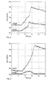
- Fig. 3 shows two sample source alpha traces from a multi-wire counter which had B and R values of 1.5 cm and 3.5 cm, respectively. While this ratio is less than ideal, compared to the specifications of Fig. 2 , it is still adequate for the purpose.
- a small 241 Am alpha source was placed within the chamber at the center of the sample region and traces were recorded using a digital signal processor with trace capture capability, the XIA DGF-4C.
- the two traces have significantly different shapes, per the discussion of the previous paragraph. However, their total charge collection times are identical, about 8.0 ⁇ s, and their initial slopes are comparable, being about 25 charge units/ ⁇ s.
- An alpha particle emitted from the backwall 44 creates an ionization track 25 ending a distance R ⁇ from the anode 40, where R ⁇ may be either positive or negative, depending upon the total track length and its angle of emission from the backwall.
- Initial charge collection will be much faster for these signals, both because the field E B in the backwall region is much higher and because any charge in the vicinity of the anode wires will also be collected rapidly due to the high fields in this region. Only charges deposited well into the source side volume will be initially collected more slowly and, by construction, this amount of charge is limited.
- the maximum collection times for backwall signals will come from tracks that penetrate maximally into the source side volume and, by construction, these times will always be less than about half t eR .
- Fig. 4 shows two backwall traces obtained by placing the alpha source on the detector backwall surface.
- the two collection times are different, but both (2.5 and 3.3 ⁇ s, respectively) are over two times faster than the sample wall collection times.
- Initial slopes are about 100 charge units/ ⁇ s, four times larger than in the sample wall case.
- charge collection times and initial slope values are fully adequate to discriminate between signal pulses according to their points of emanation in our preferred embodiment and detailed signal shape descriptions are not required.
- all signals generated by alphas emanating from the sample wall will share two characteristics.
- their total charge collection time is invariant and is given by t eR , since at least some track charge is created immediately next to the sample surface.
- t eR is about a factor of about 9 less than the typical value of t eB from backside collection and at least 25% smaller than the slowest collection from the relatively rare anode source events.
- charge collection time pulse risetime
- the slope test can be improved by dividing So by the total track charge Q T , as the ratio S 0 /Q T depends only on E R at the point of emanation, whereas So also depends upon the track charge and may vary if different energy alpha particles are present.
- the ratio S 0 /Q T becomes superior to So as a test for discriminating point of emanation when the range of alpha particle energies present within the chamber becomes large enough so that the smallest backwall So (the smallest backwall track charge times E B ) overlaps the largest sample wall So (the largest sample charge times E R ) and the simple So test can no longer unambiguously resolve the emanation point in all cases.
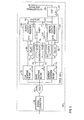
- Fig. 5 shows a block diagram of a digital processing circuit 50 that can perform the pulse shape analysis operations to determine alpha particles' points of emanation.
- the circuit comprises a section of analog signal conditioning circuitry 60 feeding an ADC 62 whose output is connected to a fast combinatorial logic circuit 64 implemented in a field programmable gate array (FPGA) that also accepts input from a clock 65 and has an output data bus 66 attached to a DSP 67.
- I/O lines 68 connect the DSP to an external interface to display the processed data or send them to an external computer for further processing, display, and/or storage as may be required.
- the circuit topology is similar to that described in the U.S. Patent of Warburton and Zhou [WARBURTON - 1999] and the issues associated with its operation will be familiar to those skilled in the art of digital spectroscopy.
- the ADC signal is split into three paths, going to a fast triangular shaping circuit 70, an intermediate peaking time triangular shaping circuit 72, and a long peaking time, trapezoidal "energy" filter 74.
- the fast shaper 70 detects pulse signals in the preamplifier output. A peaking time of 400 ns worked well for the signals shown in Figs. 3 and 4 .
- the intermediate triangular shaper measures the signals' initial slopes. Since a slope measurement after about 1 ⁇ s was found to give good differentiation between the two kinds of signals in Figs. 3 and 4 , we set this shaper's peaking time to 1 ⁇ s, and capture its output value about 1 ⁇ s after the pulse is detected.
- the gap time t g for the slow "energy” filter 74 is set to be as long as the slowest risetime signal to be measured, 8 ⁇ s in the present case. Its peaking time t p is not critical, since energy resolution in gas detectors is limited by charge induction fluctuations and not electronic noise. In the work shown, 4 ⁇ s was used, but values from 1 to 8 ⁇ s also work acceptably.
- the word "energy” has been placed in quotation marks because this actually only measures the pulses' amplitudes, which also strongly depend upon charge collection times. However, by convention, we will often refer to this as an energy measurement and, by extension, often speak of the "energy” of a pulse with the understanding that we have really only measured its amplitude.
- the fast shaper 70 feeds a discriminator 76 that has two outputs: a pulse output 77 that goes high for one clock cycle when the fast shaper output first exceeds threshold, and a level output 78 which goes high at the same time, but stays high as long as the fast shaper output exceeds threshold.
- the level output 78 gates timer 80, which counts pulses from the clock 65 to measure time T 82 above threshold, which is then our measurement of the total charge collection time.
- Pulse output 77 is delayed for 1 ⁇ s by delay 89 and then gates slope output register 88 to capture the output of the intermediate triangular shaper 72 as a measurement of the signal pulse's initial slope.
- Pulse output 77 is also delayed for time t p + t g by delay 90 to trigger energy output register 92 to capture the output of the trapezoidal energy filter 74 as a measure of the signal pulse's amplitude.
- This delayed pulse 94 can also be used to interrupt the DSP 67, signaling it that a pulse has been detected and that captured time, slope, and energy values can be read from the timer 80 and output registers 88 and 92 over the data bus 66.
- the DSP 67 completes the measurement by applying cuts (inequality tests) to the measured charge collection time and initial slope (or initial slope divided by energy) to identify the pulse as having originated at the sample or backwall and then, if desired, producing energy spectra for either or both types of pulses.
- the energy filter for example, would produce more accurate results if its gap were matched to the pulse risetime on a pulse-by-pulse basis.
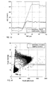
- Fig. 6 shows results for 1000 pulses each from a typical source wall location and a typical back wall location.
- Fig. 6A plots pulse risetime versus final pulse amplitude. As Fig. 6A shows, pulses from the two locations separate fairly cleanly into two distinct regions for pulses with amplitude above about 50.
- the logical test "(IF(pulse amplitude greater than 50) AND (IF(pulse risetime greater than The greater greater 4.5))" discriminates against back wall events with 98-99% accuracy, allowing the counter background from these events to be reduced by two orders of magnitude.
- Fig. 6B shows initial pulse slope, measured over the first microsecond of the pulse, plotted against pulse amplitude for the same set of signals as in Fig. 6A .
- Data from the two sources separates even more cleanly into two regions than in Fig. 6A , but a more complex logical test is required to separate them, since pulse slope is clearly proportional to pulse amplitude. Therefore, in Fig. 6C we plot initial pulse slope divided by final pulse amplitude versus final pulse amplitude. This plot very cleanly differentiates between the two different sources of ionization tracks.
- Fig. 6D shows 1000 events from a source located on the detector side wall overlaid on the plot of Fig. 6C . These events, depending upon their ionization track trajectories, can clearly be mistaken for either source wall or sample wall events. Additional means to discriminate against sidewall pulses would therefore be beneficial.
- sidewall area will be comparable to backwall area.
- Dimension B plus R will typically be about 10 cm.
- the backwall area will then be 1225 cm 2 , compared to the sidewalls' area of 1400 cm 2 .
- Fig. 2 shows the track 26 of an alpha particle emanating from the sidewall, headed toward the sample. Tracks like this will generate signals similar to signals from tracks emanating from the sample. Tracks that actually hit the sample will produce identical tracks. Similarly, tracks headed toward the backwall produce signals similar or identical to backwall signals. Sidewall tracks are thus extremely variable and are not easily separated using the tests applied to Fig. 6C .
- Fig. 7 repeats Fig. 2 , but modified by the addition of a guard wire 100 that surrounds the perimeter of the anode.
- This guard wire may either be in the same plane as the anode 40 or separated slightly from it, as shown.
- the guard wire 100 is biased similarly to the anode 40 via resistor 107 from voltage source 8 and connected to preamplifier 111 via capacitor 110.
- Preamplifier signals are then fed into a second digital processor 150.
- the digital processor 150 is a stripped down version of digital processor 50, lacking (by reference to Fig. 5 ) the clock 65, shaping filter 72, slope output register 88, DSP 67, and the control lines 68 and 94.
- guard wire processor 150 takes its clock signal from anode processor 50, so they run synchronously, and its data bus is an extension of the anode processor's data bus 66 so that the anode processor's DSP 67 can record values captured by the timer and energy output register in the guard wire processor.
- Fig. 8 shows such a pair of traces.
- the anode trace rises in about 5 ⁇ s, which might or might not pass the risetime test as a sample emission pulse.
- the significant guard wire signal could easily be used to identify this as sidewall emission pulse and reject it.
- the breaks in the two curves occur as charges are first collected on the guard wire and then on the anode and cease inducing charge on the other electrode.
- Fig. 9 shows a trace from this source location where no net charge is collected on the guard wire. The anode trace clearly passes both collection time and initial slope tests as a sample signal. A simple discriminator test on the guard wire signal, however, would reject it.
- Fig. 7 Our preferred embodiment as a multi-wire gas counter is therefore the design in Fig. 7 , which has sets of both anode and guard wires, each set having its own preamplifier and signal processor, as shown.
- the test for a good sample signal is that its charge collection time must exceed a first threshold AND its initial (slope/amplitude) must lie below a second threshold AND there is no guard wire veto signal, where a valid veto signal comprises having the veto wire collection time exceed a third threshold AND the veto energy exceed a fourth threshold.
- the four threshold values will be set to optimize performance based on the amplitudes of these signals for expected alpha particle energies and the observed noise properties of the preamplifier circuits.
- Multi-wire counters are often operated with proportional gain, since this produces larger signals, but these signals are only produced as charge actually arrives at the anode (or guard) wires. Since, in detectors with the drift field asymmetry of Fig. 7 , charge collection times will generally be slower for ionization tracks originating from the sample than from the backwall the invention method can still be applied to increase backwall event rejection. However, since collection times will be modified by track orientation, poorer rejection will result than in the preferred embodiment. Sidewall event rejection using guard wire signals will still be good.
- Our second preferred embodiment as a parallel plate ionization chamber offers three practical advantages. First, with proper plate design, the microphonics disappear. Second, by embedding the plates in their supporting medium, it becomes possible to design a detector which may merely be cleaned if it becomes contaminated, rather than having to be rebuilt. Third, for large area detectors, parallel plates have lower capacitance than a wire array of the same area, which increases signal to noise ratios, simplifies preamplifier design, and increases detector sensitivity.
- Fig. 10 shows a first embodiment of our invention as a parallel plate ionization chamber that is quite similar to the Fig. 7 design, except that the guard wires 100 and anode wires 40 have been replaced by a guard strip 200 and anode collection plate 205. The rest of the design is identical and identical part identification numbers have been used to emphasize this.
- the signals produced in this detector will be generally similar to chose produced in the Fig. 5 detector and similar means may be employed to distinguish between ionization tracks emanating from the sample and chamber backwall and to reject those emanating from the chamber sidewalls. Moreover, since the electric field can be nearly uniform everywhere within the chamber, the charge collection signals can be expressed analytically to optimize attainable rejection margins.
- Fig. 10 shows a first ionization track of length ⁇ s emanating from the sample at angle ⁇ and a second track of length ⁇ a emanating from the anode at angle ⁇ , their points of maximum extent lying distances d s and d a from the anode plane, respectively, R being the anode-to-sample separation.
- the electron charge is e, and C f is the preamplifier feedback capacitor.
- the parallel plate ionization chamber shown in Fig. 10 becomes our preferred parallel plate embodiment with the addition of the following three improvements.
- Fig. 10 The geometry of the detector Fig. 10 will not have truly uniform electric fields in its interior because the plates are too far apart, compared to their lateral dimensions and different fields result in different charge collection times which and reduce rejection margins. Increasing the guard electrodes' width W would increase field uniformity, but at the cost of greatly increasing the chamber's active volume. In our preferred embodiment, Fig. 12 , we have therefore added a field shaping electrode 210 surrounding the parallel plate chamber 30.
- This electrode can be easily manufactured, for example, as a series of stripes 212 on a printed circuit board 214, each attached to a node on a resistor divider chain, 215 which is connected to the voltage source V 8 at its anode end via an isolating resistor 217 and capacitor 218, and to ground via a lead 212 at its sample end.
- Equal valued resistors in the divider chain 215 cause the voltage at the surface of the shaping electrode 210 to smoothly pass from V at its anode end to ground at its sample end, which, in turn, forces the electric field a short distance into the chamber to lie parallel to the shaping electrode's surface, provided the chamber manifold 33 is made of a non-conducting material.
- Fig. 13 shows typical signals from sample wall 20 and anode backwall 205 ionization tracks. For equal alpha particle energies they are very different.
- the sample wall trace is three times larger than the backwall trace and has nearly three times the risetime, 28 ⁇ s compared to 10 ⁇ s. These differences make the two emission sources very easy to separate.
- Fig. 14 shows a scatter plot of 10,000 Am-241 sample wall traces and an additional 10,000 anode backwall traces
- the shown risetime cut at 18 places only 24 backwall traces and about 75 sample traces on the wrong side of the line.
- the 24 backwall correspond to a rejection ratio of 99.76%.
- the 75 lost counts correspond to a 99.25% counting efficiency.
- More complex data cuts using both risetime and amplitude information can do much better (e.g. the cut between risetime equals 30 and pulse amplitude equals 1500 yields a rejection ratio of 99.95%), but even the simple cut illustrates the invention's basic principle.
- the entire counter must operate within a grounded enclosure, comprising a cover 233 and a base plate 235. This enclosure is kept a distance R 2 ⁇ R from the anode 205, to minimize added anode capacitance and resultant preamplifier input noise.
- the inside of the parallel plate chamber using low alpha emitting materials.
- the preferred embodiment requires only two materials within the chamber: the chamber wall material itself and the anode/guard conductor material.
- plastics work well for the chamber material, being naturally low Z materials and not prone to alpha emitter contamination.
- the anode electrodes including certain stainless steels [KNOLL - 1989, pp. 724-725] or ultra-low alpha emitting N. [BROWNE - 1999]
- either the anode, 205 guard electrode, 200 or the sample mounting surface 35 can be made out of semiconductor grade Si, which is hyper pure and still has adequate conductivity for the purpose.
- Measurement chambers become contaminated by the materials they measure. With prior art systems, this is tolerated up to a point and then the detector chamber has to be rebuilt.
- Our parallel plate design may be constructed so that its internal surfaces are Smooth and free of cracks and crevices which would trap contaminating materials and so can be easily cleaned if contaminated.
- the anode and guard strip electrodes can be embedded into the plastic of their chamber wall support surface by heating the plastic into a semi-molten state or they may be applied to the chamber wall material as very thin layers by vapor deposition.
- the counter chamber becomes contaminated during the course of operation, it may be cleaned by simple washing procedures. This is an important benefit, as it allows the detector to be employed with a wider range of sample materials than might otherwise be risked.
- the atmosphere typically contains Ra at about 2.4 pCi/liter or 320 d/l-hr. [KNOLL -1989, pg. 725] This would produce an initial counting rate of about 1.2 alpha particles per second (4200/hour) in our 13 liter chamber volume. Purging the chamber to remove atmospheric O 2 therefore has the important secondary benefit of flushing most of the radon and its daughter products from the chamber.
- Thin windows make it difficult to operate prior art multi-wire counters.
- the sample has to be close to the windows since the range of alpha particles in air is very limited, but tearing or puncturing the window means rebuilding the detector.
- solid samples are placed directly inside the chamber, avoiding both alpha absorption losses in the atmosphere and the issues associated with thin windows. Chamber purging times are only a few minutes and typically insignificant compared to the counting times required for very low activity samples.
- the method could be applied to many existing alpha counters, since their internal geometries are typically not symmetrical and, even operated in proportional mode, they produce recognizable differences between particles originating from different interior locations.
- the results might not be comparable to results from a specifically designed detector, but they might offer a significant improvement over purely passive operation.
- the described counters all had rectangular geometries, while cylindrical or, indeed, arbitrary geometries could be employed.
- traces could instead be digitized and processed equivalently using an off-line computer.
Landscapes
- Physics & Mathematics (AREA)
- Health & Medical Sciences (AREA)
- Life Sciences & Earth Sciences (AREA)
- General Physics & Mathematics (AREA)
- High Energy & Nuclear Physics (AREA)
- Molecular Biology (AREA)
- Spectroscopy & Molecular Physics (AREA)
- Measurement Of Radiation (AREA)
- Electron Tubes For Measurement (AREA)
Description
- The present invention relates generally to systems for detecting and counting nuclear particles, and more particularly to reducing the background counting rate in gas filled particle counters. The specific embodiments described relate to reducing background counting rates in both multi-wire counters and ionization chambers used to detect and count alpha particles, but the same techniques could be applied to counting other charged particles as well.
- Low background alpha particle counting is important when very low concentrations of activity must be detected, such as the testing of environmental samples and of materials for the electronics industry. A particular example is the need for low alpha lead in high density packaging technologies where silicon chips are often directly soldered to a mounting substrate using ball grid arrays or related technologies. As the lead in the solder is in intimate contact with the silicon chip, it must have low alpha emissions for the chips to function reliably. The next generation of high density circuits will require lead that emits less than 0.005 α/cm2/hour, [ITRS - 1999] which is more than a factor of 10 less than can be measured with extant technologies.
- There are two major techniques presently used to measure alpha particle emission: gas filled counters and silicon spectrometers. They have similar background counting rates, but for different reasons.
- A comprehensive presentation of the distinctions between gas-filled ionization and proportional counters can be found in Knoll. [KNOLL - 1989,
Chapters 5 & 6]. Ionization chambers are simply gas filled volumes fitted with electrodes that apply an electric field to the gas and collect any charges generated therein. An alpha particle traversing the gas loses energy and produces an ionization track composed of gas ions and the electrons knocked off them. The lighter electrons drift toward the positive anode about 1000 times more quickly than the heavier ions drift toward the negative cathode. [KNOLL - 1989, pp. 131-138]. Usually only the total current is measured, giving the average rate of ion formation within the chamber. Ion chambers can be operated as pulse counters by integrating the currents the drifting electrons induce in the anode. Each ionization track then produces a single output pulse and is counted individually. [KNOLL - 1989, pp. 149-157] Because current is induced flow for the full electron drift time, the total integrated charge produced by a track depends upon both its starting location in the counter and the total track charge. Since detector capacitances are generally large and the total track charges small, signal-to-noise is poor for operation in this mode. - Proportional counters use gas avalanche gain to increase signal-to-noise. [KNOLL - 1989, pp. 160-165] This mechanism requires large electric fields, which are produced by high voltages and very thin anode wires. Because the avalanche charge is generated close to the wires, induced charge effects are eliminated, and output pulse amplitude is proportional only to initial track charge and independent of its location within the counter. Proportional counters are commonly operated in single pulse counting mode. [KNOLL - 1989, pp. 180-185] Because pulse shape is determined by the ions formed in the avalanche drifting away from the anode wire, typically in a few microseconds, all output pulses in a well designed detector have approximately the same shape.
- State of the art low background alpha counters can achieve sensitivities of about 0.05 α/cm2/hr. [IICO - 1999] They are multi-wire gas-filled proportional counters with ultra-thin entrance windows that are typically constructed as shown in
Fig. 1 . Thedetector 1 is comprised of a conducting chamber 3 filled with a countinggas 6, with a grid ofanode wires 5 suspended next to one chamber wall and sealed on the opposite side with anultra-thin window 4. The anode is biased via avoltage source 8 through alarge value resistor 7 and also connected via acapacitor 10 to a chargesensitive preamplifier 11, ashaping amplifier 13, adiscriminator 15 andcounter 16 in turn. Asample 20 placed close to theentrance window 4 emits alpha particles into the chamber. Thewindow 4 thus defines a sample region, namely that part of the chamber volume on or near which a sample is to be located. In designs having the sample located within the chamber, the chamber structure that supports the sample would help define the sample region. - The specific shown
alpha particle 22 creates anionization track 23 in countinggas 6. The track electrons drift toward theanode 5, where they are amplified by the avalanche process in the vicinity of the wires and then collected. [KNOLL - 1989, pp. 160-165] The resultant current signal is integrated by thepreamplifier 11 and shaped byamplifier 13 to produce a pulse. Discriminator 15 triggers when the pulse crosses a preset threshold T, emitting a short output pulse that is then counted by thecounter 16. - Because alpha particles emitted from the
chamber backwall 25,sidewall 26, andanode wires 27 also generate preamplifier/amplifier output pulses identical to those from thesample 20, they are also counted. The resultant background counting rate can only be reduced significantly by constructing all of the counter's components from materials having very low alpha emissivity. This approach is expensive and also becomes exponentially more difficult as ever lower backgrounds are sought, so little further improvement appears likely after 20 years of development. Gas filled counters do have the advantage that, being filled with a low density gas, they are relatively insensitive to background radiation arising from environmentally generated gamma rays and also to most cosmic rays, which are energetic muons. They can also be made quite large, with commercial units up to 30 cm by 30 cm being common. - Silicon alpha spectrometers are large area Si PIN diode detectors which are biased and connected to a charge sensitive preamplifier and amplifier much as is the counter shown in
Fig. 1 . As the energy required to produce a free electron in Si is about 10 times smaller than in counting gases, the statistics of charge generation are much better and energy resolutions of 1-2% can be obtained. Their irreducible background is set by cosmic radiation since energetic muons deposit significant charge in the Si. With 100 µm depletion depths and very careful detector design, this limit can also be reduced to about 0.05 α/cm2/hr. [ORTEC - 1998] These detectors are therefore preferred when it is desirable to identify the source of the alpha particles by measuring their emitted energies. They are also quite robust, having no anode wires or thin windows as sources of microphonics. - They have two major limitations. First, their areas are restricted, both by the unavailability of high quality Si in large areas and because small capacitances are needed to obtain their energy resolution. Second, in low activity work, the sample must be processed to extract all its radioactivity (preferably with 100% efficiency) into a small source spot for presentation to the detector. This renders these detectors impractical for measuring unprocessed or in situ samples and also adds a large overhead to measurement costs.
- The current state of the art in reducing background counting rates in gas-filled alpha counters or spectrometers is best described as "passive" in that it seeks to reduce background rates solely by the method of building the counters using materials with extremely low alpha emissivities. In contrast, the present invention provides "active" techniques for operating these same devices so as to achieve significant reductions in background counting rates.
- The present invention employs a gas-filled alpha counter that includes a gas-filled chamber having a sample region, an anode, a preamplifier connected to the anode, and a voltage source that applies a bias such that, whenever an ionization track is generated by an alpha particle passing through the gas within the chamber, the electrons in the track are collected by the anode and cause the preamplifier to produce an output signal pulse. The output pulse is associated with the alpha particle and is characteristic of the electron collection process. Thus, both the ionization track and the resultant pulse associated with a given alpha particle can be considered to have an associated region of emanation that corresponds to the region within the chamber where the ionization track originates. A minor distinction exists between our uses of regions of emission and emanation. Region of emission refers to the place where the alpha particle departed from its source. Region of emanation refers to the place where the ionization track begins within the chamber. If the source lies within the chamber the two regions are the same. If the source is external to the chamber, as in the case of
alpha particle 22, then the two regions are separated slightly. - The inventive method of operating such a gas-filled alpha counter includes, for at least some pulses, measuring one or more features of the pulse that differ depending on the pulse's region of emanation, and determining, based on the measurement of the one or more features, the pulse's region of emanation. The counter circuitry can thus be considered to include a primary feature analyzer that measures the one or more features and determines information about the pulse's region of emanation.
- Thus, it is possible to discriminate between "sample" alpha particles emitted from the sample and "background" alpha particles emitted from other surfaces within the counter and classify their associated pulses accordingly. Pulses classified as background can then be rejected, thereby effectively reducing background counting rates.
- The features that can be used in performing the pulse analysis include: pulse amplitude, duration (closely correlated with collection time), slope, slope divided by amplitude, risetime, and time of arrival, used individually or in combination.
- While these techniques can be applied to some existing chambers, in preferred embodiments, the invention contemplates constructing an alpha counter in a manner that exaggerates differences between preamplifier pulse features that result from collecting the ionization tracks generated by alpha particles emanating from different regions within the counter and then recognizing these differences in order to discriminate between the different regions of emanation. In this way, alpha particles from the sample can be counted, while alpha particles emitted from counter components can be identified, and possibly be rejected, resulting in a very low background counting rate, even in large counters.
- Two primary approaches are employed in creating and exaggerating these pulse shape differences: first, creating different electric collection fields in different regions of the counter so electron velocities and collection times are different; and, second, adjusting the counter dimensions so that charges from different regions again have different collection times, and also generate different amount of induced charge in the output. In a preferred implementation, we digitize the output pulses and use digital signal processing techniques to make the required discriminations, but analog signal processing techniques can be similarly employed.
- Two specific embodiments of the concept are described to demonstrate the relevant principles. The first embodiment is a multi-wire, gas-filled counter, wherein the grid of anode wires is placed much closer to the counter backwall than to the sample wall or entrance window and is operated without gain (i.e., in ionization chamber mode) so that it is sensitive to the flow of induced charges as ionization tracks are collected. This geometric asymmetry makes the electric field in the region between the anode and the backwall much larger than the field between the anode and the sample. Larger electron velocities in the backwall region result in induced charge signals with much larger initial slopes or risetimes than the signals induced by ionization tracks emanating from the sample region. With larger electron velocities and shorter collection distances, overall collection times for backwall ionization tracks are also much shorter than for sample ionization tracks, and this difference serves as a secondary discriminator between these two sources of activity.
- The second embodiment is an ionization chamber whose dimensions are adjusted so that drift lengths for collecting sample ionization tracks are much larger than drift lengths for collecting ionization tracks emitted from the backwall anode. This causes the sample track collection times to be much longer than anode track collection times, allowing them to be discriminated. Because their drift lengths are longer, sample tracks will also generate larger total induced charges, allowing signal slope, and, particularly, initial signal slope divided by total induced charge to be used as a secondary discriminator in this case.
- These embodiments allow reliable discriminations to be made between ionization tracks generated by the sample and ionization tracks generated by the counter backwall. We further show how improved rejection of ionization tracks emitted from the counter sidewalls can be achieved in either embodiment by the additional use of guard collectors. These guard collectors are placed about the perimeter of the anode plane, parallel to it, and both close to it and close to the sidewalls as well. They are biased at a potential close to that of the anode and connected to a second preamplifier similar to the anode's preamplifier. Ionization tracks emanating from the sidewalls deposit charge on these guard collectors, producing output pulses from the attached preamplifier. A secondary feature analyzer can then analyze the features of these pulses to identify them as emanating from the sidewalls. The simplest feature for this purpose is time of arrival: when operated in anti-coincidence with the anode, these guard collectors reliably reject sidewall source alpha emissions so that only sample source alpha particles are finally counted. Further analyzing the energy in the guard collector pulses increases the efficiency with which sample source alpha particles emanating close to the edges of the sample can be reliably identified.
- Applying these active methods to alpha particle counters fabricated with common materials such as Lucite and copper tape allows backgrounds to be achieved that are two or more orders of magnitude lower than are obtained in state of the art counters fabricated using only passive background reduction techniques. Additional background count rate reduction can be achieved by combining these active particle source recognition techniques with the passive use of very low alpha emission counter construction materials, as in existing designs.
- A further understanding of the nature and advantages of the present invention may be realized by reference to the remaining portions of the specification and the drawings.
-
Fig. 1 shows a diagram of a prior art multi-wire gas filled proportional counter and its associated electronics processing chain; -
Fig. 2 shows a diagram of an embodiment of the invention as a gas-filled multi-wire ionization chamber attached to a preamplifier and a digital signal processor and counter; -
Fig. 3 shows preamplifier output traces of charge signals induced on the anode during the collection of two ionization tracks emitted from the sample wall of the detector shown inFig. 2 ; -
Fig. 4 repeatsFig. 3 for two ionization tracks emitted from the backwall of the detector shown inFig. 2 ; -
Fig. 5 shows a block diagram of thedigital signal processor 50; -
Fig. 6A shows a scatter plot of 10-to-90% pulse risetime versus pulse amplitude for a series of signals measured from a source placed at two locations (on the sample wall and on the backwall) within the detector shown inFig. 2 ; -
Fig. 6B shows a scatter plot of initial pulse slope versus pulse amplitude for the same set of signals as inFig. 6A ; -
Fig. 6C shows a scatter plot of initial pulse slope divided by pulse amplitude versus pulse amplitude for the same set of signals as inFig. 6A ; -
Fig. 6D repeatsFig. 6C , adding signals from a source on the detector side wall; -
Fig. 7 shows a diagram of a preferred embodiment of the invention wherein guard electrodes have been added to the gas-filled multi-wire ionization chamber shown inFig. 2 ; -
Fig. 8 shows preamplifier output traces of charge signals induced on the guard and anode electrodes during the collection of an ionization track emitted from the sidewall of the detector shown inFig. 7 ; -
Fig. 9 repeatsFig. 8 for an ionization track emitted from the sample wall, where the track approaches the sidewall but does not deposit any charge on the guard electrode; -
Fig. 10 shows an embodiment of the invention as a gas-filled parallel plate ionization chamber with guard electrodes added surrounding its anode; -
Figs. 11A and 11B define distances for alpha tracks emitted from the sample and anode planes and shown analytic solutions for the induced charge signals produced as they are collected; -
Fig. 12 shows a preferred embodiment of the invention as a gas filled, parallel plate ionization chamber with guard electrodes, field shaping electrodes, and reduced anode capacitance; -
Fig. 13 shows typical preamplifier output traces of charge signals induced on the anode during the collection of one ionization track emitted from the sample wall of the detector shown inFig. 12 and one ionization track emitted from the detector's backwall; and -
Fig. 14 shows a scatter plot of pulse risetime versus pulse amplitude for a series of 10,000 ionization tracks emitted from the sample wall and 10,000 ionization tracks emitted from the anode backwall for the detector shown inFig. 12 - The invention exploits the differences in preamplifier pulse features that result from collecting ionization tracks generated by alpha particles emitted from different surfaces within the counter, and uses pulse feature analysis to recognize these differences and so distinguish between alpha particles emitted from the sample and "background" particles emitted from the surfaces of the counter itself.
- As a matter of nomenclature, the term "region of emanation" denotes the region within the chamber volume where the ionization track originates. When the sample emitting an alpha particle lies outside the chamber, the region of emanation is where the alpha particle enters the chamber, e.g.,
window 4 inFig. 1 . If the sample is inside the chamber, the region of emanation is the sample itself. In either case, the ionization track within the chamber is considered to have a region of emanation corresponding to the sample region, i.e. the region of the chamber volume at or near which a sample is to be located. Conversely, when an alpha particle is emitted from other chamber surfaces, its region of emanation is named after the region from which it is emitted. - While, strictly speaking, only the alpha particle ionization track emanates from the sample region or from another chamber surface, it is convenient to also associate the region of emanation with the preamplifier pulse that results from collecting the track charge on either the anode or guard electrode. Thus, when we refer to the pulse as having a region of emanation; this is merely shorthand for the region where the alpha particle's ionization track originated in the chamber.
- While this analysis can be used with some existing chambers, it is preferred to construct, provide, or operate a gas-filled counter in such a manner as to exaggerate the degree that the preamplifier pulse features differ as a function of the region of particle emanation. The pulse feature analysis is then even better able to recognize these differences and so distinguish between alpha particles emitted from the sample and "background" particles emitted from the surfaces of the counter itself. To illustrate the method, we describe two preferred embodiments: a multi-wire counter and a parallel plate design.
- A secondary technique, using guard electrodes, further reduces background counting rates by identifying and eliminating counts from the chambers' sidewalls, and this method is described for both preferred embodiments. Tertiary methods to further enhance the performance of the parallel-plate design by increasing the uniformity of its electric field, reducing the capacitance of its anode, and employing low alpha emitter construction materials are also described.
- The description below is organized as follows: §2 presents the multi-wire gas filled counter, including guard wires; §3 presents the parallel plate design, including guard electrodes; and §4 discusses detector operational issues.
-
Fig. 2 shows an embodiment of the invention as amulti-wire counter 30 comprising a manifold 33 containing ananode 40 of multiple wires separated by distance 42 S and sealed by aplate 35 upon which thesame sample 20 as inFig. 1 rests. This design differs from the counter ofFig. 1 as follows. First, the anode wire diameter is 5 to 10 times larger (e.g. 0.40 mm) so that, at operating voltage, the counter operates in the ionization chamber mode and not in proportional counter mode. This causes the charges induced on the anode by ionization tracks drifting within the chamber to be sensitive to the ionization track's origin and drift path. Secondly, if Rmax is the range of the most energetic alpha particle expected, then the manifold is sized so that the distance R fromsample 20 to theanode 40 is significantly longer (typically 25-30%) than Rmax and the distance B to thebackwall 44 is only a fraction (typically 1/3 to 1/4)of R. We note that, while conventional detectors may sometimes be similarly dimensioned, they are not designed so with the express intention of producing different charge collection times for particles originating from different locations within the chamber. The chamber is operated in flow mode, withconnections 47 and 49 allowing the entrance and departure of the operating gas, shown here as nitrogen. In this embodiment, the sample is therefore within the counter volume. - The bias and electronics for the counter of
Fig. 2 are identical to those used with the detector ofFig. 1 , and are identically numbered. In our preferred implementation, theamplifier 13,discriminator 15, and counter 16 ofFig. 1 are replaced by a digital processor andcounter 50. - The counter is operated in ionization chamber mode, with
voltage V 8 chosen so that the time teR required for an electron to cross R fromsample 20 to theanode 40 is a few tens of microseconds. The diameter of theanode 40 wires is then chosen so that no charge multiplication occurs in its vicinity. - The difference between lengths B and R is important to the counter's operation. The electron transit time tes across a distance s biased by a voltage V scales as s2/V in the parallel plate approximation. Thus, if R/B is, for example, 3, then teR will be 9 times the transit time teB across B from the chamber backwall 44 to the anode. We chose teR to be a few tens of microseconds, so teB is only a few microseconds, a significant difference.
- As is well known, the fields in wire chambers are not uniform, but distort in the region of the anode wires. In the present design, where S is relatively small, of
order 10% of R, the electric field will be uniform over most of R, becoming non-uniform only within distances comparable to S from the anode allowing the difference between teR and teB to be maintained. - An
ionization track 23 created by analpha particle 22 emitted from thesample 20 ends a distance R' from theanode 40. R' is always larger than zero by design, since R is greater than Rmax. As this charge drifts in the uniform field, it induces a linearly increasing charge on the anode. Once collected, it ceases to induce any further charge. Close to the anode wires however, the signal shape is difficult to predict accurately. Whether the final result is an upward signal curvature, as shown in thetrace 51 inFig. 2 , or a downward curvature depends in some detail on the length of the track, its angle to the sample, the spacing of the anode wires, and the applied voltage. -
Fig. 3 shows two sample source alpha traces from a multi-wire counter which had B and R values of 1.5 cm and 3.5 cm, respectively. While this ratio is less than ideal, compared to the specifications ofFig. 2 , it is still adequate for the purpose. A small 241Am alpha source was placed within the chamber at the center of the sample region and traces were recorded using a digital signal processor with trace capture capability, the XIA DGF-4C. The two traces have significantly different shapes, per the discussion of the previous paragraph. However, their total charge collection times are identical, about 8.0 µs, and their initial slopes are comparable, being about 25 charge units/µs. - An alpha particle emitted from the
backwall 44 creates anionization track 25 ending a distance R~ from theanode 40, where R~ may be either positive or negative, depending upon the total track length and its angle of emission from the backwall. Initial charge collection will be much faster for these signals, both because the field EB in the backwall region is much higher and because any charge in the vicinity of the anode wires will also be collected rapidly due to the high fields in this region. Only charges deposited well into the source side volume will be initially collected more slowly and, by construction, this amount of charge is limited. The maximum collection times for backwall signals will come from tracks that penetrate maximally into the source side volume and, by construction, these times will always be less than about half teR. -
Fig. 4 shows two backwall traces obtained by placing the alpha source on the detector backwall surface. The two collection times are different, but both (2.5 and 3.3 µs, respectively) are over two times faster than the sample wall collection times. Initial slopes are about 100 charge units/µs, four times larger than in the sample wall case. - Traces from alpha tracks 27 emanating from the
anode wires 40 will look much like backwall traces, since they originate within the high field regions near the anode wires. Half of these traces will penetrate into the backwall space, further contributing to their rapid charge collection characteristics. Those that penetrate into the sample space will be collected more or less quickly, depending upon their angle to the anode plane. Only those nearly perpendicular to it will have long total charge collection times, which will still be significantly shorter than teR since dimension R significantly exceeds Rmax. Anode wire source events will therefore be distinguished from true sample source events by both their large initial slopes and shorter overall collection times. - Charge collection times and initial slope values are fully adequate to discriminate between signal pulses according to their points of emanation in our preferred embodiment and detailed signal shape descriptions are not required. In particular, all signals generated by alphas emanating from the sample wall will share two characteristics. First, their total charge collection time is invariant and is given by teR, since at least some track charge is created immediately next to the sample surface. In the design of
Figure 2 , teR is about a factor of about 9 less than the typical value of teB from backside collection and at least 25% smaller than the slowest collection from the relatively rare anode source events. Thus charge collection time (pulse risetime) is a first good test for discriminating point of emanation. Second, their initial slope S0, before charge collection commences, is proportional to the field ER across R, which is lower than the field EB across B by a factor of about three and also much smaller than the fields close to the anode wires. Hence initial slope is a second good test for discriminating point of emanation. - The slope test can be improved by dividing So by the total track charge QT, as the ratio S0/QT depends only on ER at the point of emanation, whereas So also depends upon the track charge and may vary if different energy alpha particles are present. The ratio S0/QT becomes superior to So as a test for discriminating point of emanation when the range of alpha particle energies present within the chamber becomes large enough so that the smallest backwall So (the smallest backwall track charge times EB) overlaps the largest sample wall So (the largest sample charge times ER) and the simple So test can no longer unambiguously resolve the emanation point in all cases.
- We note that our ability to discriminate between backwall and sample wall emanation points depends primarily on placing the anode to break the symmetry of the counting chamber. Here we have two (backwall and sample) planes whose separation is S. By setting the inequalities B < R/3 and R> 1.25 Rmax, we cause the output pulses from the two planes to acquire their distinguishable characteristics. If the anode lay at the symmetric location, B = R, then the pulses from the two sides would become identical and indistinguishable. Alternatively, if we reversed the roles of B and R (i.e. R < B/3 and B > 1.25 Rmax) then the pulses would become distinguishable again, with sample wall tracks having fast collection times and backwall wall tracks would have slow constant collection times, etc. Thus it is the broken symmetry that leads to the ability to distinguish emanation points and not the precise arrangement we have described. In other, non-planar geometries, the same principle will apply and serve to guide the placement of the anode.
-
Fig. 5 shows a block diagram of adigital processing circuit 50 that can perform the pulse shape analysis operations to determine alpha particles' points of emanation. The circuit comprises a section of analogsignal conditioning circuitry 60 feeding anADC 62 whose output is connected to a fastcombinatorial logic circuit 64 implemented in a field programmable gate array (FPGA) that also accepts input from aclock 65 and has anoutput data bus 66 attached to aDSP 67. I/O lines 68 connect the DSP to an external interface to display the processed data or send them to an external computer for further processing, display, and/or storage as may be required. The circuit topology is similar to that described in the U.S. Patent of Warburton and Zhou [WARBURTON - 1999] and the issues associated with its operation will be familiar to those skilled in the art of digital spectroscopy. - Within the
FPGA 64 the ADC signal is split into three paths, going to a fasttriangular shaping circuit 70, an intermediate peaking timetriangular shaping circuit 72, and a long peaking time, trapezoidal "energy"filter 74. Thefast shaper 70 detects pulse signals in the preamplifier output. A peaking time of 400 ns worked well for the signals shown inFigs. 3 and 4 . The intermediate triangular shaper, an averaging differentiator, measures the signals' initial slopes. Since a slope measurement after about 1 µs was found to give good differentiation between the two kinds of signals inFigs. 3 and 4 , we set this shaper's peaking time to 1 µs, and capture its output value about 1 µs after the pulse is detected. The gap time tg for the slow "energy"filter 74 is set to be as long as the slowest risetime signal to be measured, 8 µs in the present case. Its peaking time tp is not critical, since energy resolution in gas detectors is limited by charge induction fluctuations and not electronic noise. In the work shown, 4 µs was used, but values from 1 to 8 µs also work acceptably. The word "energy" has been placed in quotation marks because this actually only measures the pulses' amplitudes, which also strongly depend upon charge collection times. However, by convention, we will often refer to this as an energy measurement and, by extension, often speak of the "energy" of a pulse with the understanding that we have really only measured its amplitude. - The
fast shaper 70 feeds adiscriminator 76 that has two outputs: apulse output 77 that goes high for one clock cycle when the fast shaper output first exceeds threshold, and alevel output 78 which goes high at the same time, but stays high as long as the fast shaper output exceeds threshold. Thelevel output 78gates timer 80, which counts pulses from theclock 65 to measure time T 82 above threshold, which is then our measurement of the total charge collection time.Pulse output 77 is delayed for 1 µs bydelay 89 and then gates slope output register 88 to capture the output of the intermediatetriangular shaper 72 as a measurement of the signal pulse's initial slope.Pulse output 77 is also delayed for time tp + tg bydelay 90 to trigger energy output register 92 to capture the output of thetrapezoidal energy filter 74 as a measure of the signal pulse's amplitude. This delayed pulse 94 can also be used to interrupt theDSP 67, signaling it that a pulse has been detected and that captured time, slope, and energy values can be read from thetimer 80 andoutput registers data bus 66. TheDSP 67 completes the measurement by applying cuts (inequality tests) to the measured charge collection time and initial slope (or initial slope divided by energy) to identify the pulse as having originated at the sample or backwall and then, if desired, producing energy spectra for either or both types of pulses. - While our preferred embodiments employ a
digital processing circuit 50 to discriminate between different points of alpha track origin, it is clear that these functions could be implemented using classical analog processing functions as well. All of thefilters discriminators 76 are common analog components, as are track and hold circuits to replace the output registers 88 and 92. A time to amplitude converter would replacetimer 80, and analog pulse delays could be used to replace both thedelays - To test the method of the preceding paragraphs, we placed an Am-241 alpha source at several locations within the detector and captured traces using an XIA DGF-4C digital signal processor with trace capture capability. We then analyzed the traces off-line using the algorithms similar to those presented in §2.5.1.
Fig. 6 shows results for 1000 pulses each from a typical source wall location and a typical back wall location.Fig. 6A plots pulse risetime versus final pulse amplitude. AsFig. 6A shows, pulses from the two locations separate fairly cleanly into two distinct regions for pulses with amplitude above about 50.
The logical test "(IF(pulse amplitude greater than 50) AND (IF(pulse risetime greater than The greater greater 4.5))" discriminates against back wall events with 98-99% accuracy, allowing the counter background from these events to be reduced by two orders of magnitude. -
Fig. 6B shows initial pulse slope, measured over the first microsecond of the pulse, plotted against pulse amplitude for the same set of signals as inFig. 6A . Data from the two sources separates even more cleanly into two regions than inFig. 6A , but a more complex logical test is required to separate them, since pulse slope is clearly proportional to pulse amplitude. Therefore, inFig. 6C we plot initial pulse slope divided by final pulse amplitude versus final pulse amplitude. This plot very cleanly differentiates between the two different sources of ionization tracks. The logical test "(IF(pulse amplitude greater than 80) AND (IF(slope/amplitude less than 0.19))" discriminates against back wall events with 99.8% accuracy (2 back wall events in 1000 sample events), allowing counter background from these events to be reduced by three orders of magnitude while maintaining about 98% efficiency for sample wall events (23 events with magnitude below 80). - These tests, however, are not so effective in discriminating against ionization tracks emanating from side wall location.
Fig. 6D shows 1000 events from a source located on the detector side wall overlaid on the plot ofFig. 6C . These events, depending upon their ionization track trajectories, can clearly be mistaken for either source wall or sample wall events. Additional means to discriminate against sidewall pulses would therefore be beneficial. - For detectors designed per the specifications of
Fig. 2 , sidewall area will be comparable to backwall area. Dimension B plus R will typically be about 10 cm. For a 1000 cm2 detector (35 cm x 35 cm) the backwall area will then be 1225 cm2, compared to the sidewalls' area of 1400 cm2.Fig. 2 shows thetrack 26 of an alpha particle emanating from the sidewall, headed toward the sample. Tracks like this will generate signals similar to signals from tracks emanating from the sample. Tracks that actually hit the sample will produce identical tracks. Similarly, tracks headed toward the backwall produce signals similar or identical to backwall signals. Sidewall tracks are thus extremely variable and are not easily separated using the tests applied toFig. 6C . -
Fig. 7 repeatsFig. 2 , but modified by the addition of aguard wire 100 that surrounds the perimeter of the anode. This guard wire may either be in the same plane as theanode 40 or separated slightly from it, as shown. Theguard wire 100 is biased similarly to theanode 40 viaresistor 107 fromvoltage source 8 and connected topreamplifier 111 viacapacitor 110. Preamplifier signals are then fed into a seconddigital processor 150. Thedigital processor 150 is a stripped down version ofdigital processor 50, lacking (by reference toFig. 5 ) theclock 65, shapingfilter 72,slope output register 88,DSP 67, and thecontrol lines 68 and 94. Instead, theguard wire processor 150 takes its clock signal fromanode processor 50, so they run synchronously, and its data bus is an extension of the anode processor'sdata bus 66 so that the anode processor'sDSP 67 can record values captured by the timer and energy output register in the guard wire processor. 150 - To view sidewall signals, we modified our
Fig. 2 detector by the addition of a guard wire, perFig. 7 , placed an Am-241 alpha source on a sidewall, and captured both anode and guard wire signals using our XIA DXP-4C module.Fig. 8 shows such a pair of traces. The anode trace rises in about 5 µs, which might or might not pass the risetime test as a sample emission pulse. The significant guard wire signal, however, could easily be used to identify this as sidewall emission pulse and reject it. The breaks in the two curves occur as charges are first collected on the guard wire and then on the anode and cease inducing charge on the other electrode. - We also measured signals in the
Fig. 7 detector with the source placed close to the edge of the sample area. Some tracks from this source location will head back toward the center of the anode, some will go straight down and some will pass over the guard wire. The latter will induce charge on the guard wire and be rejected. This loss of source counting efficiency is a penalty we must pay for eliminating sidewall counts, since the tracks are indistinguishable. More sophisticated tests allow the other two cases to be counted and not rejected.Fig. 9 shows a trace from this source location where no net charge is collected on the guard wire. The anode trace clearly passes both collection time and initial slope tests as a sample signal. A simple discriminator test on the guard wire signal, however, would reject it. Noting that no net charge is collected, we can also capture energy filter values from the guardwire signal processor 150 and specify the sidewall veto test logic to be "((IF(guard wire collection time greater than zero) AND (IF(final guard wire collected charge greater than zero))". This test maximizes sample source counting efficiency while rejecting the side wall events inFig. 6D and returning to the discrimination ratios shown inFig. 6C . - Our preferred embodiment as a multi-wire gas counter is therefore the design in
Fig. 7 , which has sets of both anode and guard wires, each set having its own preamplifier and signal processor, as shown. The test for a good sample signal is that its charge collection time must exceed a first threshold AND its initial (slope/amplitude) must lie below a second threshold AND there is no guard wire veto signal, where a valid veto signal comprises having the veto wire collection time exceed a third threshold AND the veto energy exceed a fourth threshold. The four threshold values will be set to optimize performance based on the amplitudes of these signals for expected alpha particle energies and the observed noise properties of the preamplifier circuits. - Multi-wire counters are often operated with proportional gain, since this produces larger signals, but these signals are only produced as charge actually arrives at the anode (or guard) wires. Since, in detectors with the drift field asymmetry of
Fig. 7 , charge collection times will generally be slower for ionization tracks originating from the sample than from the backwall the invention method can still be applied to increase backwall event rejection. However, since collection times will be modified by track orientation, poorer rejection will result than in the preferred embodiment. Sidewall event rejection using guard wire signals will still be good. - The previous section described a preferred embodiment of our background reduction invention as a multi-wire gas detector, and this embodiment works very well. Microphonic noise from wire vibrations is a issue, however, since we are operating without gas gain. While these may be suppressed by appropriate construction techniques, this adds complexity and makes it harder to assure that no additional alpha contamination is introduced.
- Our second preferred embodiment as a parallel plate ionization chamber offers three practical advantages. First, with proper plate design, the microphonics disappear. Second, by embedding the plates in their supporting medium, it becomes possible to design a detector which may merely be cleaned if it becomes contaminated, rather than having to be rebuilt. Third, for large area detectors, parallel plates have lower capacitance than a wire array of the same area, which increases signal to noise ratios, simplifies preamplifier design, and increases detector sensitivity.
-
Fig. 10 shows a first embodiment of our invention as a parallel plate ionization chamber that is quite similar to theFig. 7 design, except that theguard wires 100 andanode wires 40 have been replaced by aguard strip 200 andanode collection plate 205. The rest of the design is identical and identical part identification numbers have been used to emphasize this. - The signals produced in this detector will be generally similar to chose produced in the
Fig. 5 detector and similar means may be employed to distinguish between ionization tracks emanating from the sample and chamber backwall and to reject those emanating from the chamber sidewalls. Moreover, since the electric field can be nearly uniform everywhere within the chamber, the charge collection signals can be expressed analytically to optimize attainable rejection margins. -
Fig. 10 shows a first ionization track of length ρs emanating from the sample at angle β and a second track of length ρa emanating from the anode at angle α, their points of maximum extent lying distances ds and da from the anode plane, respectively, R being the anode-to-sample separation.Figs. 11a and 11b show the analytic solutions for their associated preamplifier output signals Va(t) and Vs(t), where N is the number of electrons in the full track and k = e ve/RCf, with the electron velocity ve = µeE = µeV/R, µe being the electron mobility in the detector gas, E the electric field and V the applied voltage. The electron charge is e, and Cf is the preamplifier feedback capacitor. - As before, all sample signals have the same duration, tR = R/ve. The longest signal from an anode alpha track will last taMAX = ρMAX/ve = RρMAX/µeV, where ρMAX is the maximum expected anode alpha track length. The difference between taMAX and tR is then

- R and V are then adjusted to achieve both a comfortable tR and an easily distinguished difference Δt. For example, making R = 3×ρMAX, produces a three-to-one ratio between tR and taMAX. For a typical 3.5 cm ρMAX, V is easily adjusted to get taMAX equals 3.5 µs and tR equals 10.5 µs, which are easy times to separate and to work with as well.
- From the equations in
Fig. 11a and 11b , two tracks with equal numbers of electrons have the same initial slope: Ss(0) equals Sa(0). Thus the value of slope alone cannot distinguish between them. However, if we divide by the maximum output voltage VMAX, or "energy" as measured by our energy filter, we find:

and
- For tracks of length p, the least margin M occurs between the minimum anode scaled slope (da = p) and the maximum sample scaled slope (R+ds) = 2R-p, which, for the design criterion from the previous section R = 3 ρMAX, gives MMIN = 5, so the two sets of values are always well separated. Thus, just as in the multi-wire detector case, we have two different tests for distinguishing between sample and anode tracks.
- While, in our preferred implementations, we have focused on initial slope values, the pulse's slope at later times continues to carry information and could also be used in our discrimination tests. In other implementations with different internal electric fields, slopes or scaled slopes at later points in the pulse may be more appropriate to test.
- The parallel plate ionization chamber shown in
Fig. 10 becomes our preferred parallel plate embodiment with the addition of the following three improvements. - The geometry of the detector
Fig. 10 will not have truly uniform electric fields in its interior because the plates are too far apart, compared to their lateral dimensions and different fields result in different charge collection times which and reduce rejection margins. Increasing the guard electrodes' width W would increase field uniformity, but at the cost of greatly increasing the chamber's active volume. In our preferred embodiment,Fig. 12 , we have therefore added afield shaping electrode 210 surrounding theparallel plate chamber 30. This electrode can be easily manufactured, for example, as a series ofstripes 212 on a printedcircuit board 214, each attached to a node on a resistor divider chain, 215 which is connected to thevoltage source V 8 at its anode end via an isolatingresistor 217 andcapacitor 218, and to ground via alead 212 at its sample end. Equal valued resistors in thedivider chain 215 cause the voltage at the surface of the shapingelectrode 210 to smoothly pass from V at its anode end to ground at its sample end, which, in turn, forces the electric field a short distance into the chamber to lie parallel to the shaping electrode's surface, provided thechamber manifold 33 is made of a non-conducting material. -
Fig. 13 shows typical signals fromsample wall 20 andanode backwall 205 ionization tracks. For equal alpha particle energies they are very different. The sample wall trace is three times larger than the backwall trace and has nearly three times the risetime, 28 µs compared to 10 µs. These differences make the two emission sources very easy to separate.Fig. 14 shows a scatter plot of 10,000 Am-241 sample wall traces and an additional 10,000 anode backwall traces The shown risetime cut at 18 places only 24 backwall traces and about 75 sample traces on the wrong side of the line. The 24 backwall correspond to a rejection ratio of 99.76%. The 75 lost counts correspond to a 99.25% counting efficiency. More complex data cuts using both risetime and amplitude information can do much better (e.g. the cut between risetime equals 30 and pulse amplitude equals 1500 yields a rejection ratio of 99.95%), but even the simple cut illustrates the invention's basic principle. - When the anode area is large, it becomes an excellent antenna for picking up environmental interferences. To minimize this, the entire counter must operate within a grounded enclosure, comprising a
cover 233 and abase plate 235. This enclosure is kept a distance R2 ≈ R from theanode 205, to minimize added anode capacitance and resultant preamplifier input noise. - Finally, a good way to minimize background counts is to begin with as few as possible. Therefore we construct the inside of the parallel plate chamber using low alpha emitting materials. The preferred embodiment requires only two materials within the chamber: the chamber wall material itself and the anode/guard conductor material. We have found that plastics work well for the chamber material, being naturally low Z materials and not prone to alpha emitter contamination. Various choices are possible for the anode electrodes, including certain stainless steels [KNOLL - 1989, pp. 724-725] or ultra-low alpha emitting N. [BROWNE - 1999] Finally, either the anode, 205 guard electrode, 200 or the
sample mounting surface 35 can be made out of semiconductor grade Si, which is hyper pure and still has adequate conductivity for the purpose. - Measurement chambers become contaminated by the materials they measure. With prior art systems, this is tolerated up to a point and then the detector chamber has to be rebuilt. Our parallel plate design, however, may be constructed so that its internal surfaces are Smooth and free of cracks and crevices which would trap contaminating materials and so can be easily cleaned if contaminated. For example, the anode and guard strip electrodes can be embedded into the plastic of their chamber wall support surface by heating the plastic into a semi-molten state or they may be applied to the chamber wall material as very thin layers by vapor deposition. Thus, when the counter chamber becomes contaminated during the course of operation, it may be cleaned by simple washing procedures. This is an important benefit, as it allows the detector to be employed with a wider range of sample materials than might otherwise be risked.
- The following issues need to be considered when operating either of the preferred embodiments.
- The electron affinity of the operating gas must be small, however, so that it does not trap the drifting electrons. [KNOLL - 1989, pp. 168-169] This excludes oxygen and water vapor. While any of the conventional proportional chamber gases could be used, their quenching behavior is not required because there is no charge multiplication. Thus we have found N2 as LN2 boil-off gas to be convenient, as it is cheaply available without water vapor contamination. Its low Z also reduces its sensitivity to environmental gamma rays, muons in cosmic rays, and any beta particle emitters, further contributing to a low background counting rate. We typically purge the chamber at high volume for a few minutes to remove atmospheric O2 and then lower the flow for the duration of the measurement.
- The atmosphere typically contains Ra at about 2.4 pCi/liter or 320 d/l-hr. [KNOLL -1989, pg. 725] This would produce an initial counting rate of about 1.2 alpha particles per second (4200/hour) in our 13 liter chamber volume. Purging the chamber to remove atmospheric O2 therefore has the important secondary benefit of flushing most of the radon and its daughter products from the chamber.
- Thin windows make it difficult to operate prior art multi-wire counters. The sample has to be close to the windows since the range of alpha particles in air is very limited, but tearing or puncturing the window means rebuilding the detector. In our preferred embodiments, solid samples are placed directly inside the chamber, avoiding both alpha absorption losses in the atmosphere and the issues associated with thin windows. Chamber purging times are only a few minutes and typically insignificant compared to the counting times required for very low activity samples.
- When the sample would certainly contaminate the chamber, as with powder or liquid samples, they can still be placed within the preferred embodiment detectors by covering them with a very thin foil of metallized window material. Or, indeed, one could revert to the prior art thin window design, if this offered a benefit in a particular case. The described method, clearly, does not depend upon whether the sample is physically within the chamber or not.
-
- ● BROWNE -1999: "Low-background 3He Proportional Counters for Use in the Sudbury Neutrino Observatory", M.C. Browne et al. in IEEE Transactions on Nuclear Science, Vol. 46, No. 4, pp. 873-876 (August 1999).
- ● IICO - 1999: "Model 1950 Alpha Counter", Product Literature (IICO/Spectrum Sciences, Saratoga, CA, 1999).
- ● ITRS - 1999: "International Technology Roadmap for Semiconductors, 1999 Edition", (SEMATECH, Austin, TX, 1999), p. 235.
- ● KNOLL -1989: "Radiation Detection and Measurement, 2nd Ed." by Glenn F. Knoll (J. Wiley, New York, 1989), pp. 131-159 (Chapter 5); pp. 160-198 (Chapter-6), pp. 724-725.
- ● ORTEC - 1998: "Introduction to Charged-Particle Detectors" in EG&G Ortec 97/98 Catalog "Modular Pulse-Processing Electronics and Semiconductor Radiation Detectors" (EG&G Ortec, Oak Ridge, TN, 1998), pp. 1.8-1.16.
- ● WARBURTON -1999:
U.S. Patent No. 5,873,054, issued Feb. 16, 1999 to W.K. Warburton and Z. Zhou for "Method and apparatus for combinatorial logic signal processor in a digitally based high speed x-ray spectrometer". - In the foregoing description of specific embodiments we have shown a variety examples of the general technique of active background suppression in an alpha counter whereby, by analyzing the features of pulses output by the counter, the origins of the alpha particles generating these pulses can be accurately assigned either to the sample or else to some other surface within the counter and hence rejected as background counts. How many of these features would be analyzed in any particular application would depend upon both the design of the detector and what background rejection was required. Some of these features may have been analyzed before, as, for example, pulse amplitude is commonly determined as a method for measuring particle energies. One of the inventive steps taught here is, instead, to use the results of the analysis specifically to determine each alpha particle's point of emission and hence to categorize it as either "signal" or "background."
- Therefore, the foregoing description of specific embodiments has been presented for purposes of illustration and description. It is not intended to be exhaustive or to limit the invention to the precise forms described, and obviously, many modifications and variations are possible in light of the above teaching. These embodiments were chosen and described in order to best explain the principles of the invention and its practical application to thereby enable others in the art to best utilize the invention in various embodiments and with such modifications as best suit the invention to the particular uses contemplated.
- While the above is a complete description of several specific embodiments of the invention, including methods for exaggerating the differences between pulse features produced by alpha ionization tracks originating in different locations within the detectors, other modifications, alternative constructions, and equivalents may be used.
- As a first example, the method could be applied to many existing alpha counters, since their internal geometries are typically not symmetrical and, even operated in proportional mode, they produce recognizable differences between particles originating from different interior locations. The results might not be comparable to results from a specifically designed detector, but they might offer a significant improvement over purely passive operation.
- As a second example, while we typically measured multiple pulse features, it is clear that in some cases only a single measurement would provide improved background rejection. E.g. when only a limited range of alpha particle energies is present and the sample to the anode drift distance is much larger than the backwall to the anode drift distance, pulse amplitude alone (the simplest "shape" characteristic) would suffice to distinguish between the two cases.
- As a third example, the described counters all had rectangular geometries, while cylindrical or, indeed, arbitrary geometries could be employed.
- As a fourth example, while the specific embodiments employed digital processing logic, all of the described functions could also be implemented using analog processing techniques.
- As a fifth example, while we operated our counters as windowless flow counters with initial purging, the invention does not require this. They could also be operated as sealed windowed counters when it was advantageous to do so.
- As a sixth example, while the described embodiments employ real time processing, the traces could instead be digitized and processed equivalently using an off-line computer.
- As a seventh example, while the described embodiments employ three shaping filters, other numbers of filters could clearly be used. For example, if, to improve noise performance, the peaking time of the
fast shaping filter 70 needed to be increased until it approached the value of theslope measuring filter 72, then clearly a single digital filter could serve both functions. - Therefore, the above description should not be taken as limiting the scope of the invention, as defined by the appended claims.
Claims (37)
- A method of operating a gas-filled alpha counter that includes a gas-filled chamber having a sample region, an anode disposed in the chamber to collect charges in the chamber, a preamplifier connected to the anode to receive the charge collected thereon, and a voltage source configured to, in use, apply a bias to the anode such that, whenever an ionization track is generated by an alpha particle passing through the gas within the chamber, the electrons in the track are collected by the anode and are received by the preamplifier to cause the preamplifier to produce an anode output signal pulse associated with the alpha particle, wherein the chamber and the anode are configured such that ionization tracks emanating from different surfaces of the counter produce characteristically different anode output signal pulses, the method comprising, for at least some pulses:measuring one or more features of the anode output signal pulse that differ depending on the surface of emanation of the alpha particle associated with the anode output signal pulse; anddetermining, based on the measurement of the one or more features of the anode output signal pulse, the surface of emanation of the alpha particle associated with the anode output signal pulse.
- The method of claim 1, and further comprising rejecting the pulse as background if it is determined that the pulse's associated alpha particle did not emanate from a surface corresponding to the sample region.
- The method of claim 1 wherein at least one of said measuring and determining steps is carried out by analog processing circuits.
- The method of claim 1 wherein the preamplifier output signal is conditioned and digitized by an analog-to-digital converter, and at least one of said measuring and determining steps is carried out by digital processing circuits.
- The method of claim 1 wherein:the sample region is a specified region inside the chamber;
the sample material whose alpha emission rate is to be determined is placed within the sample region; andif the sample material is capable of migrating within the counter and so contaminating it, the sample material is prevented from doing so by covering it with a piece of material that is thick enough to prevent the migration but thin enough to readily allow the alpha particles to penetrate into the volume of the counter. - The method of claim 1 wherein:the sample region is a region of the chamber adjacent a piece of window material that is thin enough to readily allow alpha particles originating outside the chamber to penetrate through the piece of material into the chamber; andthe sample material whose alpha emission rate is to be determined is placed outside of the chamber and is separated from it by the piece of window material.
- The method of claim 1 wherein the differences in the one or more anode pulse features that depend on the pulse's surface of emanation are exaggerated by constructing or operating the counter so that one or more of the following conditions are met:the counter operates in the ionization mode;substantially different electric collection fields are created proximate to different surfaces of alpha particle emanation;substantially different charge collection distances are created proximate to the different surfaces of alpha particle emanation;the one or more electrode elements that comprise the anode are placed asymmetrically within the chamber;ionization tracks emanating from the different surfaces take different amounts of time to be collected; andionization tracks emanating from the different surfaces generate different amounts of induced charge in the anode as they are collected.
- The method of claim 1 wherein the chamber has sidewalls and further information about an alpha particle's surface of emanation is obtained by:providing a guard electrode in the vicinity of the sidewalls coupling an additional preamplifier to the guard electrode;biasing the guard electrode so that, whenever an alpha particle emanating from one of the sidewalls generates an ionization track, a fraction of the electrons in the track are collected by the guard electrode and cause the additional preamplifier to produce a guard output signal pulse; andfor at least some of the measured anode output signal pulses:also measuring one or more features of the guard output signal pulses from the additional preamplifier that differ depending on the guard output signal pulse's surface of emanation;determining, based on the measurement of the one or more features of the guard pulse, whether the associated ionization track emanated from one of the sidewalls; andrejecting as background any alpha particles whose associated ionization tracks are identified as emanating from one of the sidewalls.
- The method of claim 8 wherein the one or more features of the guard pulse include at least one of the following:the guard output signal pulse's time of arrival relative to that of the anode output signal pulse; andthe final change in the guard output signal pulse's amplitude.
- The method of claim 9 wherein, for the alpha particle to be rejected, the guard output signal pulse must arrive in coincidence with anode output signal pulse; and
the amount of total charge collected on the guard electrode must exceed a threshold. - The method of claim 8 wherein:the anode is comprised of wires lying approximately within a plane;the chamber is bounded in part by two nominally parallel walls, one of which is associated with the sample region;the anode wire plane is nominally parallel to the walls but is asymmetrically placed in that it is significantly closer to one wall than to the other wall; andthe guard electrode comprises one or more additional wires enclosing the perimeter of the anode wires and lying in approximately the same plane.
- The method of claim 8 wherein the anode and the sample region are both planes, approximately parallel to each other, and separated by a distance that is significantly longer than the range of the most energetic alpha particles to be found within the chamber; and
the guard electrode surrounds the perimeter of the anode and lies in the same or approximately the same plane as the anode. - The method of claim 12 wherein an additional field shaping electrode structure is used to increase the electric field uniformity in the volume between the anode and the sample region.
- The method of claim 12 wherein the anode and guard electrode are embedded flush within a supporting insulator structure in such a manner that the resulting composite structure is free of cracks and voids and may be easily cleaned to remove such contaminating materials as may accumulate in the course of counter operation.
- The method of claim 1 wherein the one or more features of the anode pulse include at least one of the following:the pulse's duration;the pulse's amplitude;the pulse's slope; andthe pulse's slope divided by its amplitude.
- The method of claim 15 wherein the duration is measured by a timer that is gated by a discriminator whose output goes high whenever its input exceeds a preset threshold, where the input to the discriminator is the preamplifier signal filtered by a shaping filter whose time constant is fast compared to a typical pulse risetime.
- The method of claim 15 wherein the slope is measured by an averaging differentiator filter whose output is captured shortly after the pulse is initially detected.
- The method of claim 15 wherein the pulse amplitude is measured using a trapezoidal filter whose gap is set to exceed the longest expected pulse 0-to-100% risetime and whose output is captured at a predetermined time after the pulse is initially detected.
- The method of claim 15 wherein the pulse amplitude is measured by capturing the value of an averaging filter shortly after the pulse maximum is detected and subtracting from that value an output value of the same averaging filter captured shortly before the pulse is initially detected.
- The method of claim 1 wherein the background counting rate is further reduced by constructing the alpha counter from materials having low alpha particle emission rates.
- An alpha particle counter comprising:a gas-filled chamber having a sample region;an anode disposed in the chamber to collect charges in the chamber;a preamplifier connected to said anode to receive the charge collected thereon;a voltage source configured to, in use, apply a bias to the anode such that, whenever an ionization track is generated by an alpha particle passing through said gas within said chamber, the electrons in said track are collected by said anode and are received by the preamplifier to cause said preamplifier to produce an anode output signal pulse associated with the alpha particle;wherein the chamber and the anode are configured such that ionization tracks emanating from different surfaces of the counter produce characteristically different anode output signal pulses; and a primary pulse feature analyzer configured to:measure the one or more features of an anode output signal pulse that differ depending on the pulse's surface of emanation; anddetermine, based on the measurement of the one or more features of the anode output signal pulse, the surface within the chamber from which the ionization track generated by the alpha particle emanated.
- The counter of claim 21 wherein said primary pulse feature analyzer is further configured to reject the pulse as background if it determines that the pulse's associated alpha particle did not emanate from the sample region, thereby reducing the counter's background counting rate.
- The counter of claim 21 wherein the counter has one or more of the following features of construction or operation that serve to produce or exaggerate the differences in said anode pulse features:operation is in the ionization mode;there are substantially different electric collection fields proximate to the different regions of alpha particle emanation;there are substantially different charge collection distances proximate to the different regions of alpha particle emanation;one or more of the electrode elements that comprise the anode are placed asymmetrically within the chamber;ionization tracks from the different regions of alpha particle emanation have substantially different charge collection times; andionization tracks from the different regions generate substantially different amounts of induced charge in the anode as they are collected.
- The counter of claim 21, wherein the counter has sidewalls, and further comprising:a guard electrode in the vicinity of said sidewalls;an additional preamplifier connected to said guard electrode;an additional voltage source that biases said guard electrode so that said guard electrode collects electrons from ionization tracks and said additional preamplifier produces guard output signal pulses; anda secondary pulse feature analyzer that:measures the one or more features of said guard output signal pulses;determines, based on the measurement of the one or more features of the guard pulses, additional information about the surface from which the pulse's associated alpha particle emanated; andrejects the pulse as background if it determines that the pulse's associated alpha particle emanated from one of said chamber sidewalls, thereby reducing the counter's background counting rate.
- The counter of claim 24 wherein, said secondary pulse feature analyzer rejects the alpha particle when it determines that:the guard output signal pulse arrived in coincidence with the anode output signal pulse; andthe total amount of charge collected on the guard electrode exceeded a threshold.
- The counter of claim 24 wherein:said anode is comprised of wires lying approximately within a plane;said chamber is bounded in part by two nominally parallel walls, one of which is associated with said sample region;said plane within which said wires lie is nominally parallel to said walls but is asymmetrically placed in that it is significantly closer to one of said walls than to the other of said walls; andsaid guard electrode is comprised of one or more additional wires that enclose the perimeter of the anode wires and lie in approximately the same plane.
- The counter of claim 24 wherein said anode and said sample region are both planes, parallel to each other, and separated by a distance that is significantly longer than the range of the most energetic alpha particles to be found within said chamber; and
said guard electrode surrounds the perimeter of said anode and lies in the same or approximately the same plane and the anode. - The counter of claim 26, and further comprising an additional field shaping electrode structure that increases the electric field uniformity in the volume between said anode and said sample region.
- The counter of claim 21 wherein said primary pulse feature analyzer includes means for determining one or more of the following:the pulse's duration;the pulse's amplitude;the pulse's slope; andthe pulse's slope divided by its amplitude.
- The counter of claim 29 wherein said primary pulse feature analyzer determines pulse duration using:a shaping filter, whose time constant is significantly shorter than that of a typical pulse risetime;a discriminator whose output goes high whenever its input from said shaping filter exceeds a preset threshold; anda timer that is gated by the output of said discriminator.
- The counter of claim 29 wherein said primary pulse feature analyzer determines slope using:an averaging differentiation filter; andmeans for capturing said filter's output shortly after the pulse is initially detected.
- The counter of claim 29 wherein said primary pulse feature analyzer determines pulse amplitude using: a trapezoidal filter whose gap is set to exceed the longest expected pulse 0-to-100% risetime; and
means for capturing said filter's output at a predetermined time after the pulse is initially detected. - The counter of claim 21, and further comprising:an analog-to-digital converter to digitize said preamplifier output signal; and a digital signal processing circuit implementing part or all of said primary pulse feature analyzer.
- The counter of claim 33 wherein said digital signal processing circuit comprises at least:a set of combinatorial logic, which carries out pulse feature analysis operations at the clock speed of said analog-to-digital converter; anda digital computing device, which carries out pulse feature analysis operations at the pulse event rate.
- The counter of claim 21 wherein the gas used in said chamber is nitrogen.
- The counter of claim 21 wherein the counter is purged with nitrogen prior to the start of counting in order to remove radon and its decay products.
- The counter of claim 21 wherein the sample material whose alpha emission rate is to be determined is placed within a specified region inside of said chamber, and
if the sample material is capable of migrating within the counter and so contaminating it, the sample material is covered with a piece of material that is thick enough to prevent the migration but thin enough to readily allow the alpha particles to penetrate into the volume of the counter.
Applications Claiming Priority (3)
| Application Number | Priority Date | Filing Date | Title |
|---|---|---|---|
| US938136 | 2001-08-23 | ||
| US09/938,136 US6732059B2 (en) | 2001-08-23 | 2001-08-23 | Ultra-low background gas-filled alpha counter |
| PCT/US2002/026839 WO2003019206A1 (en) | 2001-08-23 | 2002-08-22 | Ultra-low background gas-filled alpha counter |
Publications (3)
| Publication Number | Publication Date |
|---|---|
| EP1419397A1 EP1419397A1 (en) | 2004-05-19 |
| EP1419397A4 EP1419397A4 (en) | 2011-06-08 |
| EP1419397B1 true EP1419397B1 (en) | 2013-06-05 |
Family
ID=25470956
Family Applications (1)
| Application Number | Title | Priority Date | Filing Date |
|---|---|---|---|
| EP02757333.6A Expired - Lifetime EP1419397B1 (en) | 2001-08-23 | 2002-08-22 | Ultra-low background gas-filled alpha counter |
Country Status (4)
| Country | Link |
|---|---|
| US (1) | US6732059B2 (en) |
| EP (1) | EP1419397B1 (en) |
| JP (1) | JP4667746B2 (en) |
| WO (1) | WO2003019206A1 (en) |
Cited By (1)
| Publication number | Priority date | Publication date | Assignee | Title |
|---|---|---|---|---|
| WO2026111574A1 (en) * | 2024-11-22 | 2026-05-28 | Saf Tehnika, As | Low-intensity alpha particle detection device ionization chamber with electric current pulse amplifier |
Families Citing this family (28)
| Publication number | Priority date | Publication date | Assignee | Title |
|---|---|---|---|---|
| JP3741006B2 (en) * | 2001-08-08 | 2006-02-01 | 株式会社日立製作所 | Charged particle measuring apparatus and measuring method thereof |
| US7277511B2 (en) * | 2002-05-15 | 2007-10-02 | Intellon Corporation | Two-stage non-linear filter for analog signal gain control in an OFDM receiver |
| US7105831B1 (en) * | 2003-04-09 | 2006-09-12 | The United States Of America As Represented By The Secretary Of The Army | Ambient air alpha particles ionization detector |
| US6943712B1 (en) | 2003-11-06 | 2005-09-13 | Marvell International Ltd. | Voltage built-in real-time digital non-linearity measurement device and method for analog to digital converters |
| US20050194541A1 (en) * | 2004-03-03 | 2005-09-08 | Clark Brett M. | Large area ionization detector and methods for detecting low level radiation |
| US7564039B1 (en) * | 2004-06-17 | 2009-07-21 | Integrated Sensors, Llc | Dual substrate plasma panel based ionizing radiation detector |
| US7525098B2 (en) * | 2006-04-05 | 2009-04-28 | Orbotech Ltd. | High resolution energy detector |
| US7528377B2 (en) * | 2006-12-26 | 2009-05-05 | Orbotech Medical Solutions Ltd. | Radiation detector circuit |
| US8158449B2 (en) * | 2008-10-08 | 2012-04-17 | International Business Machines Corporation | Particle emission analysis for semiconductor fabrication steps |
| JP4880077B1 (en) * | 2011-02-16 | 2012-02-22 | 株式会社リガク | X-ray detection signal processing apparatus and method |
| US9012865B2 (en) * | 2012-05-01 | 2015-04-21 | Canberra Industries, Inc. | Radiation detector system and method |
| CN105143918A (en) * | 2013-04-24 | 2015-12-09 | 皇家飞利浦有限公司 | Pulse processing circuit with correction means |
| EP2990832A1 (en) * | 2014-08-29 | 2016-03-02 | Sercel | Data acquisition apparatus using one single local clock |
| US10224192B2 (en) * | 2017-07-21 | 2019-03-05 | Atonarp Inc. | High-speed low-noise ion current detection circuit and mass spectrometer using the same |
| US11417509B2 (en) | 2017-07-21 | 2022-08-16 | Atonarp Inc. | Current detection device and spectrometer using ihe same |
| US11646190B2 (en) | 2017-07-21 | 2023-05-09 | Atonarp Inc. | Current detection device and spectrometer using the same |
| US10367667B2 (en) * | 2017-09-29 | 2019-07-30 | Nxp B.V. | Joint ad-hoc signal and collision detection method |
| CN109839656B (en) * | 2019-02-22 | 2022-12-13 | 成都理工大学 | Digital anti-coincidence HPGe spectrometer system based on alpha particle event reading |
| DE102019104710B4 (en) * | 2019-02-25 | 2023-04-27 | Ketek Gmbh | Method of operating a radiation detection system and radiation detection system |
| CN110333179B (en) * | 2019-07-10 | 2021-06-15 | 中国科学院近代物理研究所 | A deep space charged particle detector triggering method |
| CN110441599B (en) * | 2019-07-15 | 2021-05-28 | 深圳市鼎阳科技股份有限公司 | Detection method and device for frequency spectrograph and readable storage medium |
| CN110658549B (en) * | 2019-10-15 | 2023-04-07 | 中国工程物理研究院材料研究所 | Background medium and weak signal-to-noise ratio improving method and application |
| CN113433581B (en) * | 2021-06-25 | 2022-12-30 | 中国科学技术大学 | Low-background alpha and beta ray detection device |
| CN114662419B (en) * | 2022-03-09 | 2026-02-03 | 中广核工程有限公司 | System and method for evaluating background of pipeline deposition source item under power operation working condition of nuclear power plant |
| CN115201887A (en) * | 2022-06-23 | 2022-10-18 | 深圳市计量质量检测研究院 | Ultralow background alpha particle detector and alpha particle measuring method |
| CN116338758B (en) * | 2023-01-03 | 2026-01-09 | 中国原子能科学研究院 | A method for processing a proportional counter |
| DE102025102590B3 (en) * | 2025-01-24 | 2026-01-15 | Berthold Technologies Gmbh & Co. Kg | Device and system for measuring alpha and beta radiation activity of radioactive aerosols of artificial origin |
| CN120370376B (en) * | 2025-06-26 | 2025-09-02 | 北京大学 | Method for measuring (n, alpha) reaction angle differential section |
Family Cites Families (14)
| Publication number | Priority date | Publication date | Assignee | Title |
|---|---|---|---|---|
| US3869608A (en) * | 1949-10-05 | 1975-03-04 | Scherbatskoy Serge Alexander | Nuclear well logging |
| US3721825A (en) | 1970-12-03 | 1973-03-20 | J Rasmussen | Method and apparatus for analysis of liquid residues using nuclear reactions |
| US4104523A (en) * | 1976-10-06 | 1978-08-01 | Martin Marietta Corporation | Electronic alpha particle counter |
| US4317038A (en) * | 1980-03-24 | 1982-02-23 | Agence Nationale De Valorisation De La Recherche | Device for determining the spatial distribution of radiation |
| JPS57158576A (en) * | 1981-03-27 | 1982-09-30 | Hitachi Ltd | Radiant ray measuring device |
| DE3129431C2 (en) * | 1981-07-25 | 1984-02-09 | FAG Kugelfischer Georg Schäfer KGaA, 8720 Schweinfurt | Apparatus for simultaneous measurement of α and β rays with a proportional counter tube operated in the β plateau, a linear preamplifier and two pulse height discriminators |
| JPH01102885U (en) * | 1987-12-26 | 1989-07-11 | ||
| JPH0432144A (en) * | 1990-05-25 | 1992-02-04 | Toshiba Corp | Variable characteristic ionization chamber |
| DE4021617C2 (en) * | 1990-07-06 | 1993-12-02 | Kugelfischer G Schaefer & Co | Device for the continuous measurement of the iron content in zinc layers |
| US5059803A (en) | 1990-07-19 | 1991-10-22 | The United States Of America As Represented By The Secretary Of The Army | Rugged alpha particle counter |
| US5192868A (en) * | 1991-08-07 | 1993-03-09 | Tennelec/Nucleus Inc. | Proportional counter detector |
| US5525804A (en) * | 1995-02-01 | 1996-06-11 | The Regents Of The University Of California | Background canceling surface alpha detector |
| JP4083802B2 (en) * | 1995-08-14 | 2008-04-30 | ワーバートン,ウィリアム,ケイ. | Method for digital-based high-speed X-ray spectrometer |
| US5873054A (en) | 1995-08-14 | 1999-02-16 | William K. Warburton | Method and apparatus for combinatorial logic signal processor in a digitally based high speed x-ray spectrometer |
-
2001
- 2001-08-23 US US09/938,136 patent/US6732059B2/en not_active Expired - Lifetime
-
2002
- 2002-08-22 EP EP02757333.6A patent/EP1419397B1/en not_active Expired - Lifetime
- 2002-08-22 JP JP2003524020A patent/JP4667746B2/en not_active Expired - Fee Related
- 2002-08-22 WO PCT/US2002/026839 patent/WO2003019206A1/en not_active Ceased
Cited By (1)
| Publication number | Priority date | Publication date | Assignee | Title |
|---|---|---|---|---|
| WO2026111574A1 (en) * | 2024-11-22 | 2026-05-28 | Saf Tehnika, As | Low-intensity alpha particle detection device ionization chamber with electric current pulse amplifier |
Also Published As
| Publication number | Publication date |
|---|---|
| US20030040877A1 (en) | 2003-02-27 |
| EP1419397A4 (en) | 2011-06-08 |
| WO2003019206A1 (en) | 2003-03-06 |
| EP1419397A1 (en) | 2004-05-19 |
| JP4667746B2 (en) | 2011-04-13 |
| JP2005501261A (en) | 2005-01-13 |
| US6732059B2 (en) | 2004-05-04 |
Similar Documents
| Publication | Publication Date | Title |
|---|---|---|
| US6732059B2 (en) | Ultra-low background gas-filled alpha counter | |
| US5231290A (en) | Neutron coincidence detectors employing heterogeneous materials | |
| US9885674B2 (en) | Method and device for recognition of a material making use of its transmission function | |
| GB2316744A (en) | Nuclear spectroscopy signal processing system | |
| US4264816A (en) | Ionization chamber | |
| Fricke et al. | Single particle counting of heavy ions with a channeltron detector | |
| US5907156A (en) | Wide range radiation detector | |
| CN118915123A (en) | Fast neutron detector, detection device and detection method | |
| Craig et al. | ‘Blind time’–current limitations on laser ablation multi-collector inductively coupled plasma mass spectrometry (LA-MC-ICP-MS) for ultra-transient signal isotope ratio analysis and application to individual sub-micron sized uranium particles | |
| Schneider et al. | Mass-identification of alpha-particles and heavy ions by time-of-flight methods | |
| US5026988A (en) | Method and apparatus for time of flight medium energy particle scattering | |
| US6627898B2 (en) | Method and system for monitoring radiation and rejecting noise | |
| Downie et al. | High-resolution position-sensing resistive anode microchannel plate detector systems suitable for megahertz count-rates | |
| Pansky et al. | Applications of gaseous electron counting detectors | |
| Agnetta et al. | GREX/COVER_PLASTEX: an experiment to analyze the space-time structure of extensive air showers produced by primary cosmic rays of 1015 eV | |
| US4629897A (en) | Automatic high insulation switch | |
| US7791018B2 (en) | Electronic read-out circuits for pixilated/resistive charge detectors | |
| US3435207A (en) | Apparatus for measuring velocity of low energy electrons | |
| Beghini et al. | A compact parallel plate detector for heavy ion reaction studies | |
| Mazur et al. | Position sensitive multiwire proportional parallel plate detector for heavy ions | |
| Padmore et al. | A fast multianode detector for solid state ultraviolet photoelectron spectroscopy | |
| Van Sambeek et al. | A Recoil Detector for electron scattering experiments with internal targets | |
| Tanaka et al. | Beta-spectroscopy of low level samples by a coincidence type scintillation spectrometer | |
| Baldini et al. | The AMS time of flight system | |
| Wells et al. | Operation of a BaF2-TMAE prototype detector |
Legal Events
| Date | Code | Title | Description |
|---|---|---|---|
| PUAI | Public reference made under article 153(3) epc to a published international application that has entered the european phase |
Free format text: ORIGINAL CODE: 0009012 |
|
| 17P | Request for examination filed |
Effective date: 20040309 |
|
| AK | Designated contracting states |
Kind code of ref document: A1 Designated state(s): AT BE BG CH CY CZ DE DK EE ES FI FR GB GR IE IT LI LU MC NL PT SE SK TR |
|
| AX | Request for extension of the european patent |
Extension state: AL LT LV MK RO SI |
|
| A4 | Supplementary search report drawn up and despatched |
Effective date: 20110506 |
|
| 17Q | First examination report despatched |
Effective date: 20110718 |
|
| GRAP | Despatch of communication of intention to grant a patent |
Free format text: ORIGINAL CODE: EPIDOSNIGR1 |
|
| GRAS | Grant fee paid |
Free format text: ORIGINAL CODE: EPIDOSNIGR3 |
|
| GRAA | (expected) grant |
Free format text: ORIGINAL CODE: 0009210 |
|
| RIN1 | Information on inventor provided before grant (corrected) |
Inventor name: WAHL, JOHN Inventor name: WARBURTON, WILLIAM, K. Inventor name: MOMAYEZI, MICHAEL |
|
| AK | Designated contracting states |
Kind code of ref document: B1 Designated state(s): AT BE BG CH CY CZ DE DK EE ES FI FR GB GR IE IT LI LU MC NL PT SE SK TR |
|
| AX | Request for extension of the european patent |
Extension state: AL LT LV MK RO SI |
|
| REG | Reference to a national code |
Ref country code: GB Ref legal event code: FG4D |
|
| REG | Reference to a national code |
Ref country code: CH Ref legal event code: EP |
|
| REG | Reference to a national code |
Ref country code: AT Ref legal event code: REF Ref document number: 615957 Country of ref document: AT Kind code of ref document: T Effective date: 20130615 |
|
| REG | Reference to a national code |
Ref country code: IE Ref legal event code: FG4D |
|
| RAP2 | Party data changed (patent owner data changed or rights of a patent transferred) |
Owner name: WARBURTON, WILLIAM K. |
|
| RIN2 | Information on inventor provided after grant (corrected) |
Inventor name: WARBURTON, WILLIAM, K. Inventor name: MOMAYEZI, MICHAEL Inventor name: WAHL, JOHN |
|
| REG | Reference to a national code |
Ref country code: DE Ref legal event code: R096 Ref document number: 60245076 Country of ref document: DE Effective date: 20130801 |
|
| REG | Reference to a national code |
Ref country code: NL Ref legal event code: T3 |
|
| REG | Reference to a national code |
Ref country code: AT Ref legal event code: MK05 Ref document number: 615957 Country of ref document: AT Kind code of ref document: T Effective date: 20130605 |
|
| PG25 | Lapsed in a contracting state [announced via postgrant information from national office to epo] |
Ref country code: ES Free format text: LAPSE BECAUSE OF FAILURE TO SUBMIT A TRANSLATION OF THE DESCRIPTION OR TO PAY THE FEE WITHIN THE PRESCRIBED TIME-LIMIT Effective date: 20130916 Ref country code: GR Free format text: LAPSE BECAUSE OF FAILURE TO SUBMIT A TRANSLATION OF THE DESCRIPTION OR TO PAY THE FEE WITHIN THE PRESCRIBED TIME-LIMIT Effective date: 20130906 Ref country code: SE Free format text: LAPSE BECAUSE OF FAILURE TO SUBMIT A TRANSLATION OF THE DESCRIPTION OR TO PAY THE FEE WITHIN THE PRESCRIBED TIME-LIMIT Effective date: 20130605 Ref country code: AT Free format text: LAPSE BECAUSE OF FAILURE TO SUBMIT A TRANSLATION OF THE DESCRIPTION OR TO PAY THE FEE WITHIN THE PRESCRIBED TIME-LIMIT Effective date: 20130605 Ref country code: FI Free format text: LAPSE BECAUSE OF FAILURE TO SUBMIT A TRANSLATION OF THE DESCRIPTION OR TO PAY THE FEE WITHIN THE PRESCRIBED TIME-LIMIT Effective date: 20130605 |
|
| REG | Reference to a national code |
Ref country code: LT Ref legal event code: MG9D |
|
| PG25 | Lapsed in a contracting state [announced via postgrant information from national office to epo] |
Ref country code: BG Free format text: LAPSE BECAUSE OF FAILURE TO SUBMIT A TRANSLATION OF THE DESCRIPTION OR TO PAY THE FEE WITHIN THE PRESCRIBED TIME-LIMIT Effective date: 20130905 |
|
| PG25 | Lapsed in a contracting state [announced via postgrant information from national office to epo] |
Ref country code: SK Free format text: LAPSE BECAUSE OF FAILURE TO SUBMIT A TRANSLATION OF THE DESCRIPTION OR TO PAY THE FEE WITHIN THE PRESCRIBED TIME-LIMIT Effective date: 20130605 Ref country code: PT Free format text: LAPSE BECAUSE OF FAILURE TO SUBMIT A TRANSLATION OF THE DESCRIPTION OR TO PAY THE FEE WITHIN THE PRESCRIBED TIME-LIMIT Effective date: 20131007 Ref country code: EE Free format text: LAPSE BECAUSE OF FAILURE TO SUBMIT A TRANSLATION OF THE DESCRIPTION OR TO PAY THE FEE WITHIN THE PRESCRIBED TIME-LIMIT Effective date: 20130605 Ref country code: CZ Free format text: LAPSE BECAUSE OF FAILURE TO SUBMIT A TRANSLATION OF THE DESCRIPTION OR TO PAY THE FEE WITHIN THE PRESCRIBED TIME-LIMIT Effective date: 20130605 |
|
| PLBE | No opposition filed within time limit |
Free format text: ORIGINAL CODE: 0009261 |
|
| STAA | Information on the status of an ep patent application or granted ep patent |
Free format text: STATUS: NO OPPOSITION FILED WITHIN TIME LIMIT |
|
| PG25 | Lapsed in a contracting state [announced via postgrant information from national office to epo] |
Ref country code: DK Free format text: LAPSE BECAUSE OF FAILURE TO SUBMIT A TRANSLATION OF THE DESCRIPTION OR TO PAY THE FEE WITHIN THE PRESCRIBED TIME-LIMIT Effective date: 20130605 Ref country code: MC Free format text: LAPSE BECAUSE OF FAILURE TO SUBMIT A TRANSLATION OF THE DESCRIPTION OR TO PAY THE FEE WITHIN THE PRESCRIBED TIME-LIMIT Effective date: 20130605 |
|
| 26N | No opposition filed |
Effective date: 20140306 |
|
| REG | Reference to a national code |
Ref country code: DE Ref legal event code: R097 Ref document number: 60245076 Country of ref document: DE Effective date: 20140306 |
|
| PG25 | Lapsed in a contracting state [announced via postgrant information from national office to epo] |
Ref country code: TR Free format text: LAPSE BECAUSE OF FAILURE TO SUBMIT A TRANSLATION OF THE DESCRIPTION OR TO PAY THE FEE WITHIN THE PRESCRIBED TIME-LIMIT Effective date: 20130605 Ref country code: CY Free format text: LAPSE BECAUSE OF FAILURE TO SUBMIT A TRANSLATION OF THE DESCRIPTION OR TO PAY THE FEE WITHIN THE PRESCRIBED TIME-LIMIT Effective date: 20130605 |
|
| PG25 | Lapsed in a contracting state [announced via postgrant information from national office to epo] |
Ref country code: LU Free format text: LAPSE BECAUSE OF NON-PAYMENT OF DUE FEES Effective date: 20130822 |
|
| REG | Reference to a national code |
Ref country code: FR Ref legal event code: PLFP Year of fee payment: 15 |
|
| REG | Reference to a national code |
Ref country code: FR Ref legal event code: PLFP Year of fee payment: 16 |
|
| REG | Reference to a national code |
Ref country code: FR Ref legal event code: PLFP Year of fee payment: 17 |
|
| PGFP | Annual fee paid to national office [announced via postgrant information from national office to epo] |
Ref country code: BE Payment date: 20190617 Year of fee payment: 18 |
|
| PGFP | Annual fee paid to national office [announced via postgrant information from national office to epo] |
Ref country code: NL Payment date: 20190814 Year of fee payment: 18 |
|
| PGFP | Annual fee paid to national office [announced via postgrant information from national office to epo] |
Ref country code: IT Payment date: 20190821 Year of fee payment: 18 Ref country code: FR Payment date: 20190711 Year of fee payment: 18 Ref country code: DE Payment date: 20190806 Year of fee payment: 18 Ref country code: IE Payment date: 20190813 Year of fee payment: 18 |
|
| PGFP | Annual fee paid to national office [announced via postgrant information from national office to epo] |
Ref country code: GB Payment date: 20190822 Year of fee payment: 18 |
|
| PGFP | Annual fee paid to national office [announced via postgrant information from national office to epo] |
Ref country code: CH Payment date: 20190819 Year of fee payment: 18 |
|
| REG | Reference to a national code |
Ref country code: DE Ref legal event code: R119 Ref document number: 60245076 Country of ref document: DE |
|
| REG | Reference to a national code |
Ref country code: CH Ref legal event code: PL |
|
| REG | Reference to a national code |
Ref country code: NL Ref legal event code: MM Effective date: 20200901 |
|
| GBPC | Gb: european patent ceased through non-payment of renewal fee |
Effective date: 20200822 |
|
| PG25 | Lapsed in a contracting state [announced via postgrant information from national office to epo] |
Ref country code: CH Free format text: LAPSE BECAUSE OF NON-PAYMENT OF DUE FEES Effective date: 20200831 Ref country code: LI Free format text: LAPSE BECAUSE OF NON-PAYMENT OF DUE FEES Effective date: 20200831 |
|
| REG | Reference to a national code |
Ref country code: BE Ref legal event code: MM Effective date: 20200831 |
|
| PG25 | Lapsed in a contracting state [announced via postgrant information from national office to epo] |
Ref country code: FR Free format text: LAPSE BECAUSE OF NON-PAYMENT OF DUE FEES Effective date: 20200831 Ref country code: IT Free format text: LAPSE BECAUSE OF NON-PAYMENT OF DUE FEES Effective date: 20200822 Ref country code: DE Free format text: LAPSE BECAUSE OF NON-PAYMENT OF DUE FEES Effective date: 20210302 |
|
| PG25 | Lapsed in a contracting state [announced via postgrant information from national office to epo] |
Ref country code: BE Free format text: LAPSE BECAUSE OF NON-PAYMENT OF DUE FEES Effective date: 20200831 Ref country code: IE Free format text: LAPSE BECAUSE OF NON-PAYMENT OF DUE FEES Effective date: 20200822 Ref country code: GB Free format text: LAPSE BECAUSE OF NON-PAYMENT OF DUE FEES Effective date: 20200822 |
|
| PG25 | Lapsed in a contracting state [announced via postgrant information from national office to epo] |
Ref country code: NL Free format text: LAPSE BECAUSE OF NON-PAYMENT OF DUE FEES Effective date: 20200901 |