Technical Field
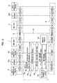
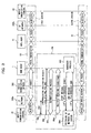
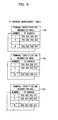
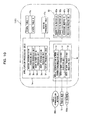
The present invention relates to a server,
a mobile communication terminal, a radio apparatus,
a communication method in a communication system and
a communication system suitable for use in a
communication system which can concurrently use
different kinds of networks, that is, a mobile
communication network and another network (for
example, Internet communication network).
Background Art
Since environments of mobile computing are
prepared and the mobile communication network and IP
(internet protocol) network (referred also as TCP/IP
communication network or IP packet network) are both
developed quickly, a mobile communication terminal
can access to the IP network over the mobile
communication network to get a service provided by the
IP network. A terminal such as a personal computer
(hereinafter abbreviated as a personal computer)
connected to the IP network can transmit/receive an
electronic mail and the like to/from a mobile
communication terminal over the IP network and the
mobile communication network. By connecting the both
networks, various services are realized.
However, while the mobile communication
terminal is accessing to the mobile communication
network to get the service provided by the IP network
over the mobile communication network, the mobile
communication terminal cannot switch the network to
be accessed from the mobile communication network to
LAN (Local Area Network) and continue the TCP/IP
communication.
Conversely, when the mobile communication
terminal moves, for example, from the first floor of
the company to the outside of the building while
accessing to the LAN, the data communication path
established between the mobile communication
terminal and a server installed on the floor is
disconnected. Accordingly, when the mobile
communication terminal is in communication to receive
an electronic mail, for example, the mobile
communication terminal loses the communication data
(for example, the electronic mail data). For this,
the user (a subscriber or a person who operates the
mobile communication terminal) has to dial once more
(re-dial) to the mobile communication network to newly
set a data communication channel via a base station,
an exchanger, etc., and again communicate.
Consequently, while the user is
communicating important data, the user is limited
his/her movement in order to avoid disconnection of
the packet session (referred as a communication
session, occasionally; hereinafter abbreviated as a
session, occasionally) for transmitting/receiving IP
packets (IP datagram) , which spoils portability of the
mobile communication terminal.
In the light of the above problem, an object
of the present invention is to provide a server, a
mobile communication terminal, a radio apparatus, a
communication method in a communication system, and
a communication system, by which a mobile
communication terminal can transfer between the
mobile communication network and the packet
communication network with the mobile communication
terminal continuing the communication.
Disclosure of Invention
(1) A server according to this invention
disposed in a packet network to repeat a packet between
a first terminal and a second terminal comprises a
session managing unit storing a first address of the
first terminal assigned to a first session
representing a connection status between the server
of its own and the terminal and a second address of
the first terminal assigned to a second session
representing a connection status between the server
of its own and the first terminal, a receiving unit
receiving a packet containing user data from the
second terminal, a switching unit switching f rom the
first session of a packet having the first address as
a destination and containing the user data to the
second session of a packet having the second address
as the destination and containing the user data on the
basis of the addresses stored in the session managing
unit, and a transmitting unit transmitting the packet
using the second session switched by the switching
unit.
Accordingly, while carrying out a data
communication in a mobile communication network or a
packet network, the user can freely move between
different kinds of networks with the communication
being continued.
(2) A server according to this invention
disposed in a packet network to repeat a packet between
a first terminal and a second terminal comprises a
session managing unit storing a first address of the
first terminal assigned to a first session
representing a connection status between the server
of its own and the first terminal and a second address
of the first terminal assigned to a second session
representing a connection status between the server
of its own and the first terminal, a receiving unit
receiving a packet having the first address or the
second address as a source address and containing user
data from the first terminal in the first session or
the second session, and a transmitting unit
transmitting a packet containing the user data in the
received packet and having an address of the server
of its own as the source address to the second terminal
in both the first session and the second session.
Accordingly, the user can be handed over
seamlessly, that is, without hindrance.
Additionally, it is possible to reduce the resources
of the networks, and decrease the connection charge.
(3) The first address may be either an address
assigned by a mobile communication network or an
address assigned by the IP network, and the second
address may be the other address. Accordingly, data
transmission/reception becomes possible without
largely changing the existing installations.
(4) The first session may be either a session
in which the first terminal communicates with the IP
network over a mobile communication network or a
session in which the first terminal directly accesses
to the IP network to communicate with the same, and
the second session may be the other session.
Accordingly, synchronous sessions are set so that
simultaneous data communications become possible.
(5) The switching unit may monitor a quality
of a radio signal transmitted from the first terminal
in the first session, and switch the first session or
the second session on the basis of predetermined
detection. Accordingly, packets obtained from
different sessions can be appropriately transmitted
and received.
(6) A mobile communication terminal
according to this invention accessing to a mobile
communication network connected to a packet network
to be able to carry out a packet communication with
a server in the packet network comprises an access
obtaining unit directly accessing to the packet
network, not over the mobile communication network,
to obtain an access for a packet communication, a
control unit controlling the address obtaining unit
to obtain an address when a predetermined operation
is performed on the mobile communication terminal or
it is detected that a direct access to the packet
network becomes possible during the packet
communication with the server, and a switching unit
switching the packet communication with the server to
a packet communication by a direct access to the packet
network using the address obtained by the address
obtaining unit.
Accordingly, it is possible to dynamically
switch the data transmission path with a movement of
the portable terminal. Additionally, each of
establishment of multiple sessions, a
synchronization registration and a data transmission
session is registered, exchanged and switched,
whereby the network environments can be dynamically
changed.
(7) A mobile communication terminal
according to this invention directly accessing to a
packet network connected to a mobile communication
terminal, not over the mobile communication network,
to be able to carry out a packet communication with
a server in the packet network comprises an address
obtaining unit directly accessing to the mobile
communication network to obtain an address for a
packet communication, a control unit controlling the
address obtaining unit to obtain an address when a
predetermined operation is performed on the mobile
communication terminal or it is detected that a direct
access to the packet network becomes possible during
the packet communication with the server, and a
switching unit switching the packet communication
with the server to a packet communication by a direct
access to the mobile communication network using the
address obtained by the address obtaining unit.
Accordingly, even when the mobile
communication terminal moves to a different kind of
network during a data communication, seamless
handover becomes possible so that the user can avoid
a trouble.
(8) The control unit may notify the server
of the obtained address before the switching.
Accordingly, each of the mobile terminals can
multiplex a plurality of sessions. Further, the
portable terminal can transmit and receive data such
as a short message, for example.
(9) The switching unit may switch according
to an instruction from the server. Accordingly,
synchronous sessions are set for data
transmission/reception, and concurrent data
communication becomes possible. Additionally, the
amount of investment in the packet network can be
small.
(10) The switching unit may stop to transmit
a packet for the packet communication with the server
according to a first instruction from the server,
switch according to a second instruction after the
first instruction, and start to transmit a packet.
Accordingly, large capacity transmission becomes
possible.
(11) A radio apparatus according to this
invention disposed in a packet network to carry out
a radio communication with a mobile communication
terminal comprises a measuring means measuring a
receive quality in the radio communication, and a
transmitting unit transmitting a received packet from
the mobile communication terminal, a measured receive
quality or deterioration information generated on the
basis of the receive quality to a server in the packet
network which is in communication with the mobile
communication terminal.
Accordingly, an address is dynamically given
to the mobile communication terminal so that the
mobile communication terminal can be appropriately
managed.
(12) A communication method in a
communication system according to this invention
comprising a server disposed in a packet network and
a mobile communication terminal being able to access
to both a mobile communication network connected to
the packet network and the packet network, comprises
the steps of sending a packet to be transmitted when
the mobile communication terminal carries out a packet
communication with another terminal via the server,
and controlling a source address of the packet to the
another terminal by the server so that the source
address of the packet remains unchanged before and
after a switching of the network to which the mobile
communication terminal accesses.
Accordingly, it is possible to improve the
secrecy of data between the portable terminal and a
communication destination terminal, transmit and
receive a large capacity of data, and establish a
plurality of different synchronous sessions coping
with the communication. Additionally, it is possible
to re-connect without re-dialing, so that the load of
communication monitoring can be diminished.
(13) The communication method in a
communication system according to this invention in
claim 12 further comprises the steps of notifying of
an address to be used in a network to be switched to
from the mobile communication terminal when the
network to which the mobile communication terminal
accesses is switched, and switching a destination
address of a packet from the another terminal to the
notified address by the server when the network to
which the mobile communication terminal accesses is
switched.
Accordingly, when the user accesses to the
IP network, it is possible to decrease the number of
resources of repeating networks transferring IP
packet data, and shorten the delay time of the packet
data.
(14) A communication method in a
communication system according to this invention
comprises a first session communication step at which
a first terminal communicates with a first server in
a packet network over a mobile communication network
using a first session representing a connection status
between the first terminal and the first server, a
synchronous communication step at which the first
server starts a synchronous communication with a
second server in the packet network, a synchronization
registration request transmission step at which the
first terminal transmits a synchronization
registration request using a packet communication set
between the first terminal and the first server, a
second session establishment step at which a second
session representing a direct connection status
between the first server having received the
synchronization registration request and the first
terminal is established, a handover step at which the
first server having received the synchronization
registration request hands over, a switching step at
which the first terminal switches from the mobile
communication network to the packet network, and a
communication step at which the first terminal
communicates with the second terminal over the
switched packet network using the synchronous
communication started at the switching step.
Accordingly, two sessions are established
between the mobile communication terminal and the home
agent in the packet network so that the session used
to transmit and receive packets between the home agent
and the mobile communication terminal is switched.
(15) A communication system according to this
invention comprises a packet network, a mobile
communication network connected to the packet network,
a server disposed in the packet network to repeat a
packet between a first terminal and a second terminal;
and the first terminal transmitting/receiving a
packet to/from the server directly or over the mobile
communication network, the server comprising a
session managing unit storing a first address of the
first terminal assigned to a first session
representing a connection status between the server
of its own and the first terminal and a second address
of the first terminal assigned to a second session
representing a connection status between the server
of its own and the first terminal, a receiving unit
receiving a packet containing user data from the
second terminal, a switching unit switching from the
first session of a packet having the first address as
the destination and containing the user data to the
second session of a packet having the second address
as a destination and containing the user data on the
basis of the addresses stored in the session managing
unit and a transmitting unit transmitting the packet
in the second session switched by the switching unit,
the mobile communication terminal comprising a
transmitting/receiving unit transmitting/receiving
a packet to/from the server in the packet network
directly or over the mobile communication network
connected to the packet network, an address obtaining
unit obtaining an address for a packet communication
from the packet received by the
transmitting/receiving unit, generating a packet
having the obtained address and directly accessing to
the packet network, an address managing unit storing
the address for the packet communication obtained by
the address obtaining unit, a control unit controlling
the address obtaining unit to obtain the address for
the packet communication when detecting a
predetermined operation or a status in which a direct
access to the packet network becomes possible during
the packet communication with the server over the
mobile communication network, and a switching unit
switching from the packet communication with the
server over the mobile communication network to a
packet communication by a direct access to the server
when the control unit detects, and inputting the
address for a packet stored in the address managing
unit to the address obtaining unit.
Accordingly, it is possible to diminish the
load on the server, effectively manage the network,
and avoid the communication from being disconnected.
Further, it is possible to initiate a number of users,
and multiplex sessions.
Brief Description of Drawings
FIG. 1 is a diagram showing a structure of
a communication system according to a first embodiment
of this invention;
FIG. 2 is a diagram for illustrating handover
between different kinds of networks according to the
first embodiment of this invention;
FIG. 3 is a diagram for illustrating another
handover between different kinds of networks
according to the first embodiment of this invention;
FIG. 4 is a schematic functional block
diagram of a base station according to the first
embodiment of this invention;
FIG. 5 is a schematic functional diagram of
an access server according to the first embodiment of
this invention;
FIG. 6 is a schematic functional diagram of
a mobile communication terminal according to the first
embodiment of this invention;
FIG. 7 is a schematic block diagram of a radio
hub according to the first embodiment of this
invention;
FIG. 8 is a schematic functional block
diagram of a repeating server according to the first
embodiment of this invention;
FIG. 9 is a diagram showing an example of an
IP address management table according to the first
embodiment of this invention;
FIG. 10 is a functional block diagram of a
home agent according to the first embodiment of this
invention;
FIG. 11 is a diagram showing an example of
a SyncML table according to the first embodiment of
this invention;
FIG. 12 is a diagram showing a sequence for
illustrating SyncML synchronization restration;
FIG. 13 is a diagram showing a sequence for
illustrating SyncML communication;
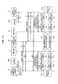
FIG. 14 is a diagram showing a sequence in
which the mobile communication terminal 1
communicates with a communication destination
terminal over an IP network;
FIG. 15 is a diagram showing an example of
a session management table according to the first
embodiment of this invention;
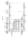
FIG. 16 is a diagram showing a sequence for
illustrating a switching process from a first session
to a second session;
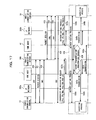
FIG. 17 is a diagram showing a communication
sequence over a mobile communication network
according to the first embodiment of this invention;
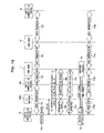
FIG. 18 is a diagram showing a handover
sequence from the mobile communication network to the
IP network according to the first embodiment of this
invention;
FIGS. 19(a) and 19(b) are diagrams for
illustrating an effect provided when this invention
is applied;
FIGS. 20(a) and 20(b) are diagrams for
illustrating another effect provided when this
invention is applied;
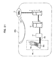
FIG. 21 is a schematic diagram showing a
structure of an IP network according to a first
modification of the first embodiment of this
invention;
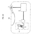
FIG. 22 is a schematic diagram showing a
structure of an IP network according to a second
modification of the first embodiment of this
invention;
FIG. 23 is a diagram showing a structure of
a communication system according to a second
embodiment of this invention.
Best Mode for Carrying Out the Invention
(A) Description of First Embodiment of the Invention
(A-1) Principle of the Invention
FIG. 1 is a diagram showing a structure of
a communication system 100 according to a first
embodiment of this invention. The communication
system 100 shown in FIG. 1 comprises a mobile
communication network 300 and an IP packet network
(hereinafter referred as an IP network 200,
occasionally) connected to each other.
The mobile communication network 300 is a
network allowing accesses by radio in a wide range,
such as a PDC (Personal Digital Cellular) system, a
PHS (Personal Handy Phone System), a W-CDMA
(Wideband-Code Division Multiple Access) system or
the like. The mobile communication network 300
comprises base stations 300a and 300d as being
apparatuses for radio communication, routing
apparatuses 300b and 300c, and access servers 310a and
310b as being apparatuses for IP address assignment
and protocol conversion.
The IP network 200 is a communication network
using Internet protocol, and is a network being able
to transmit/receive data by means of TPC/IP (Transport
Control Protocol/Internet Protocol). The IP network
200 comprises, for example, IP packet networks (IP
networks) 200a and 200b which are private IP networks,
and an IP network 400c which is a public IP network.
The IP networks 200a and 200b comprise radio
hubs (radio hub apparatuses) 11 and 51 as being
apparatuses carrying out local radio communication,
repeating servers 12 and 52 as being apparatuses
assigning IP addresses and repeating IP packets, and
home agent servers 1 (first server: hereinafter
referred as a home agent, occasionally) and 41 (second
server: hereinafter referred as a home agent,
occasionally), respectively. Incidentally, all or a
part of the IP networks 200a, 200b and 400c can be
shared.
The home agents 1 and 41 are servers disposed
in the IP networks 200a and 200b, respectively, to
repeat IP packets between a movable communication
terminal 10 and a mobile communication terminal 50.
Reference characters 10 and 50 denotes mobile
communication terminals used in this communication
system 100, each of which can communicate with the
mobile communication network 300. The mobile
communication terminal 10 carries out a packet
communication (a communication using IP packets) via
the home agent 1 and the radio hub 11 of the IP network
200a or over a mobile communication network connected
to the IP network 200a. The mobile communication
terminal 10 comprises a main body unit 10a having an
accessing function to the mobile communication
network 300 and a radio adapter 10b for connecting by
radio to the radio hubs 11 and 51.
Whereby, each of the mobile communication
terminals 10 and 50 can communicate with the mobile
communication terminal 50 or 10 by both an access to
the IP network 200 over the mobile communication
network 300 and a direct access to the IP network 200.
Each of the mobile communication terminals 10 and 50
can access to the IP network 200 while accessing to
the mobile communication network 300. Conversely,
each of the mobile communication terminals 10 and 50
can access to the mobile communication network 300
while accessing to the IP network 200. Additionally,
a TCP/IP communication between the mobile
communication terminals 10 and 50 is via led either
the home agent 1 or 41.
Meanwhile, a party with which the mobile
communication terminal 10 communicates may be a
personal computer or the like connected to the IP
network 200b in lieu of the mobile communication
terminal (hereinafter referred as a communication
destination terminal, occasionally) 50.
Hereinafter, description will be made of a
communication method between the mobile
communication terminals 10 and 50 using the
communication system 100.
FIG. 2 is a diagram for illustrating handover
between different types of networks (from the mobile
communication network 300 to the IP network 200a)
according to the first embodiment of this invention,
where a session Q1, a session Q3 and a handover process
Q2 for shifting from the session Q1 to the session Q3
are shown.
The session Q1 is a session in which the
mobile communication terminal 10 communicates with
the home agent 1 (the IP network 200a) over the mobile
communication network 300. In the session Q1, the
mobile communication terminal 10 first accesses to the
mobile communication network 300. The mobile
communication terminal 10 establishes a session with
the mobile communication network 300 to
transmit/receive IP packets for the mobile
communication network (hereinafter referred as
packets for mobile communication network,
occasionally). The mobile communication network 300
transmits/receives IP packets to/from the home agent
1 of the IP network 200a. The home agent 1
communicates with the home agent 41 using SyncML
protocol. The home agent 41 transmits/receives IP
packets to/from the radio hub 51 (refer to FIG. 1)
disposed in the IP network 200b. The radio hub 51
communicates with the mobile communication terminal
50 using a short distance radio communication protocol
(Bluetooth protocol). Details of these protocols
will be described later.
The session Q3 is a session in which the
mobile communication terminal 10 directly accesses to
the IP network 200a to communicate with the home agent
1. In this case, the mobile communication terminal
10 first accesses to the IP network 200a. The mobile
communication terminal 10 communicates with the radio
hub 11 (refer to FIG. 1) using Bluetooth protocol.
The radio hub 11 transmits/receives IP packets to/from
the home agent 1. The mobile communication terminal
10 communicates with the communication destination
terminal 50, over a SyncML communication between the
home agents 1 and 41, a packet communication between
the home agents 41 and the IP network 200b and a
Bluetooth communication between the IP network 200b
and the mobile communication terminal 50.
In the handover process Q2, the mobile
communication terminal 10 in communication in the
session Q1 accesses to the IP network 200a to be given
an IP address IP'a, whereby the mobile communication
terminal 10 gets into a status (Q2a) in which the
TCP/IP communication is possible. The mobile
communication terminal 10 establishes a session with
the home agent 1 directly from the IP network, and
transmits a synchronization registration request
message (referred also as a synchronization
registration request signal or a synchronization
registration request) to the home agent 1 using an IP
packet in order to assign this session for handover
(Q2b) .
In FIG. 2, IPsa and the like in parentheses
of the synchronization registration request message
(message Q2b) show elements of the IP packet. "IPsa"
and "IP'a" before ";" are a header, showing the
destination and the source of the IP packets in this
order. "SNa," "IPsb," "SNb" and "IP" after ";" are
contents contained in the data part (this notation
being common to descriptions in parentheses in other
drawings).
"IPsa" in the IP header is an IP address of
the home agent 1. "IP'a" is an IP address assigned
to the mobile communication terminal 10 for the
session Q3. The IP address "IPsa" is identified by
the IP networks 200a and 200b, and other IP networks.
The IP address "IP'a" is identified by only the IP
network 200a.
"SNa, " "IPsb, " "SNb" and "IP" in the data part
represent terminal identification information on the
mobile communication terminal 10, an IP address of the
home agent 41 to which the communication destination
terminal 50 registers synchronization, terminal
identification information on the mobile
communication terminal 50 and a session type,
respectively. The session type is classified into
"IP" and "mobile." "IP" represents that the mobile
communication terminal 10 is directly connected to the
IP network 200a (the home agent 1). "Mobile"
represents that the mobile communication terminal 10
is connected to the home agent 1 over the mobile
communication network 300. Incidentally, the
terminal identification information "SNa" and "SNb"
is beforehand stored in the home agents 1 and 41, and
managed by the same.
When receiving the synchronization
registration request message, the home agent 1
authenticates whether or not "SNa" contained in the
message coincides with identification information
stored therein (Q2c). When it is determined through
the authentication that the mobile communication
terminal 10 is a terminal qualified to get the service,
a session for handover is established between the
mobile communication terminal 10 and the home agent
1 (Q2d), the home agent 1 carries out a handover
process (Q2f), and the network to which the mobile
communication terminal 10 accesses is switched from
the mobile communication network 300 to the IP network
200a in the mobile communication terminal 10 (Q2e).
More details of the processes Q2f and Q2e are
as follows. In the process Q2f, the home agent 1
notifies a start of the handover process as a start
message to the mobile communication terminal 10 over
the IP network 200a or the mobile communication
network 300, and notifies an end of the handover
process as an end message to the mobile communication
terminal 10 over the IP network 200a or the mobile
communication network 300, as well.
When receiving the start message, the mobile
communication terminal 10 stops the packet
communication with the mobile communication terminal
50 over the mobile communication network 300, and
prepares to switch it to the packet communication over
the IP network 200a. When the mobile communication
terminal 10 recognizes that preparation of the
handover is completed in the home agent 1 by receiving
the end message, the mobile communication terminal 10
resumes packet transmission, which has been stopped,
to the IP network 200a, whereby the switching is
carried out.
As above, two sessions are established
between the mobile communication terminal 10 and the
home agent 1 in the IP network 200a, and the session
for transmitting/receiving packets between the home
agent 1 and the mobile communication terminal 10 is
switched.
On the other hand, in handover between
different types of networks, from the IP network 200a
to the mobile communication network 300, there are
carried out a session Q3, a handover process Q4, and
a session Q1, as shown in FIG. 3.
In the handover process Q4, the mobile
communication terminal 10 is connected by dialing up
to the mobile communication network 300 using PPP
(Point to Point Protocol) (Q4a), and is assigned an
IP address "IP"a" by the access server 310a. The
mobile communication terminal 10 transmits a
synchronization registration request message
containing "IP"a" to the home agent 1. After the home
agent 1 authenticates the synchronization
registration request message (Q4c), the second
session in which the mobile communication network 300
to be accessed is established (Q4d), and a handover
process (Q4f) in the home agent 1 and an access
switching from the mobile communication network 300
to the IP network 200a in the mobile communication
terminal 10 (Q4e) are carried out.
As above, the mobile communication terminal
10 can switch between two sessions with the home agent
1 at need.
The home agents 41 and 1, and the mobile
communication terminals 50 and 10 may be connected
over wires in spite of by radio. This method will be
described later in a first modification of the first
embodiment.
(A-2) Detailed Structure of the Communication System
of the Invention
Next, detailed description will be made of
the mobile communication network 300, the mobile
communication terminals 10 and 50, and the IP networks
200a, 200b and 400c for use to realize a communication
method in the above communication system.
(1) Mobile Communication Network 300
The mobile communication network 300 shown
in FIG. 1 is connected to the IP networks 200a and 200b,
and other subscriber fixed telephone network (not
shown). The mobile communication network 300
comprises the base stations (BS) 300a and 300d, the
exchangers (EX) 300b and 300c, and the access servers
310a and 310b.
The mobile communication network 300 may be
provided with a plurality of base stations. In which
case, the mobile communication network 300 is equipped
with a base station control apparatus or the like for
controlling assignment of channels to the plural base
stations or anything.
(1-1) Base Stations 300a and 300d, and Exchangers
300b and 300c
The base station 300a receives a radio signal
[radio data: hereinafter referred as an RF (Radio
Frequency) signal, occasionally] transmitted from
the mobile communication terminal 10, demodulates the
radio signal and transmits the demodulated data to the
exchanger 300b, while modulating data transmitted
from the exchanger 300b and transmitting an RF signal
to the mobile communication terminal 10. The base
station 300d is similar in function to the base station
300a, which transmits/receives data to/from the
mobile communication terminal 50 and the exchanger
300c.
Each of the exchangers 300b and 300c is used
as an apparatus having a function of routing IP packets
for mobile communication network (hereinafter
referred as packets for mobile communication network,
occasionally) from the base stations 300a and 300d or
other exchanger (not shown). Incidentally,
"routing" signifies transferring of an IP packet to
the most suitable router, server or the like according
to the destination of the IP packet, which mainly
stands for processing in the network layer. These
exchangers 300b and 300c may be replaced with routers
when the mobile communication network 300 additonally
has the TCP/IP communication function.
FIG. 4 is a schematic functional block
diagram of the base station 300a according to the first
embodiment of this invention. The base station 300a
shown in FIG. 4 comprises a mobile communication
antenna unit 301e, a mobile communication radio unit
301f and a control unit 301a.
The mobile communication antenna unit 301e
is an antenna for transmitting/receiving RF signals.
The mobile communication radio unit 301f carries out
a transmitting/receiving process such as
modulation/demodulation and the like of RF signals,
including an RF circuit (not shown). The control unit
301a controls or anything a unit disposed in the base
station 300 to convert the data format between the
exchanger 300b and the mobile communication radio unit
301f.
The base station 300d is similar in structure
to the base station 300a.
(1-2) Access Servers 310a and 310b
The access server 310a converts a packet for
mobile communication network transmitted in the
mobile communication network 300 into an IP packet
which can be transmitted in the IP network 200a, and
transmits the IP packet to the IP network 200a, while
converting an IP packet from the IP network 200a into
a packet for mobile communication network and
transmitting the packet to the exchanger 300b.
Namely, the access server 310a has a function of
converting the protocol from one to another between
the mobile communication network 300 and the IP
network 200a. Further, the access server 310a has a
function of assigning an IP address to the mobile
communication terminal 10 when receiving an IP address
assignment request message from the mobile
communication terminal 10, and transmitting the
assigned IP address to the mobile communication
terminal 10.
FIG. 5 is a schematic functional block
diagram of the access server 310a according to the
first embodiment of this invention. The access
server 310a shown in FIG. 5 comprises a data converting
unit 310c, a PPP connecting process unit (PPP
connecting unit) 310d, a TCP/IP processing unit 310e,
an operating system 301c and a CPU (Central Processing
Unit) 301d. Incidentally, like reference characters
in FIG. 5 designate like or corresponding part or like
or corresponding functions, detailed descriptions of
which are thus omitted.
The TCP/IP processing unit 310e carries out
a TCP/IP process on an IP packet. The PPP connecting
process unit 310d assigns an IP address to the mobile
communication terminal 10 according to PPP by which
the mobile communication terminal 10 is
dial-up-connected. The data converting unit 310c
converts an IP packet for mobile communication network
outputted from the exchanger 300b into the TCP/IP
format. The converted IP packet is transmitted from
the TCP/IP processing unit 310e to the IP network 200a.
On the other hand, an IP packet received by the TCP/IP
processing unit 310e is converted into a packet for
mobile communication network by the data converting
unit 310c, and outputted to the exchanger 300b.
Accordingly, the communication system 100
can fuse the mobile communication network 300 and the
IP network 200a to enable data communication with each
other. The access server 310b is similar in structure
to the access server 310a.
Whereby, a user A (a person who operates the
mobile communication terminal 10) can access to the
access server 310a via the base station 300a to
communicate with the home agent 1. The user A can
access to the access server 310b and another access
server (not shown) via the access server 310a. A user
B (a person who operates the mobile communication
terminal 50) can be connected to a desired IP network
via the access server 310b.
As above, the user A and the user B can carry
out data communication via the access servers 310a and
310b, respectively.
(2) Mobile Communication Terminals 10 and 50
An example of the mobile communication
terminals 10 and 50 shown in FIG. 1 is a cellular phone
which can access to the mobile communication network
300 and the IP network 200a to communicate, which
comprises a cellular phone function unit 10a and a
radio adapter 10b.
FIG. 6 is a schematic function block diagram
of the mobile communication terminal 10 according to
the first embodiment of this invention. The mobile
communication terminal 10 shown in FIG. 6 comprises
a fifth transmitting/receiving unit 14, a radio
adapter 10b, and a terminal application processing
unit 10c. The fifth transmitting/receiving unit 14
and the terminal application processing unit 10c
correspond to the cellular phone function unit 10a
shown in FIG. 1.
The radio adapter 10b and the fifth
transmitting/receiving unit 14 to be described later
cooperate with each other to function as the
transmitting/receiving units 10b or 14 which
transmits and receives a packet to/from the home agent
1 in the IP network 200a, directly or over the mobile
communication network 300.
(2-1) Fifth Transmitting/Receiving Unit 14
The fifth transmitting/receiving unit 14 has
a function of accessing to the mobile communication
network 300 to carry out data communication such as
voice communication, packet communication and the
like, for example. The fifth transmitting/receiving
unit 14 comprises a mobile communication antenna unit
10f which transmits/receives an RF signal to/from the
base station 300a, and a mobile communication radio
unit 10g which carries out a transmitting/receiving
process on an RF signal inputted/outputted from/to the
mobile communication antenna unit 10f.
(2-2) Radio Adapter 10b
The radio adapter unit 10b functions as a
Bluetooth protocol processing unit for establishing
a communication with a radio hub 11 in order to access
to the IP network 200a.
The Bluetooth protocol is a short distance
radio communication protocol, which enables a short
distance communication within a range from about 10m
(meters) to 100m. According to the protocol, a net
called a piconet having one master machine and seven
slave machines is configured. Namely, the radio hub
11 (refer to FIG. 1) functions as the master machine,
while the radio adapter 10b functions as the slave
machine.
The radio hub 11 can simultaneously
transmit/receive data to/from a maximum of seven radio
adapters 10b by time division multiplex access.
Accordingly, the radio hub 11 can carry out a
one-to-many communication in the IP network 200a.
The relation between the master machine and
the slave machine may be converted. Namely, the radio
adapter 10b may function as the master machine,
whereas the radio hub 11 and radio adapters (not shown)
of other mobile communication terminals may function
as the slave machines.
The radio adapter 10b comprises, for example,
a Bluetooth antenna unit 10i, a Bluetooth radio unit
10h and a Bluetooth processing unit (a short distance
radio communication protocol processing unit) 10j.
The Bluetooth antenna unit 10i is an antenna for
transmitting/receiving an RF signal using Bluetooth
protocol, which transmits an RF signal to the radio
hub 11 and receives an RF signal from the radio hub
11. The Bluetooth radio unit 10h has a function for
a receiving process on an RF signal received by the
Bluetooth antenna unit 10i, and a function of
converting a signal from the Bluetooth processing unit
10h into an RF signal and inputting the RF signal into
the Bluetooth antenna unit 10i. The Bluetooth radio
unit 10h includes an RF circuit. Whereby, an RF
signal is transmitted and received using Bluetooth
protocol between the mobile communication terminal 10
and the radio hub 11.
The Bluetooth processing unit 10j has a
function of controlling the Bluetooth radio unit 10h
to transmit/receive a control signal to/from the radio
hub 11, and establishing a session according to the
Bluetooth protocol with the radio hub 11. The
Bluetooth processing unit 10j also has a function of,
after the session is established, converting an IP
packet from the terminal application processing unit
10c into data in a format according to the Bluetooth
protocol, inputting the data into the Bluetooth radio
unit 10h, while converting data from the Bluetooth
radio unit 10h into IP packet data and inputting the
data into the terminal application processing unit 10c.
Each of these functions is accomplished by a CPU, a
ROM (Read Only Memory) or a RAM, etc. of the portable
terminal 10a.
The radio adapter 10b may be provided inside
a casing of the mobile communication terminal 10. The
functions of the radio adapter 10 may be integrated
into the portable terminal 10a, or may be connected
to the portable terminal 10a with a cable and a
connecter (not shown) to be detachable from the mobile
communication terminal 10a.
The mobile communication terminal 50 is
similar in structure to the mobile communication
terminal 10 shown in FIG. 6, further description of
which is thus omitted.
(2-3) Terminal Application Processing Unit 10c
The terminal application processing unit 10c
comprises a packet communication encryption
processing unit 4a, a decryption processing unit 4n,
a TCP/IP processing unit (an address obtaining unit)
4f, a handover processing unit 4b, an agent
authentication processing unit 4d, an agent
synchronization processing unit (a control unit) 4e,
an agent information unit 4c, an IP address managing
unit (an address managing unit) 4g and a mobile
communication connection processing unit 4h.
Next, description will be made of these
processing units.
The encryption processing unit 4a encrypts
data to be transmitted to a communication destination
terminal (the mobile communication terminal) 50, a
cellular phone, the home agent 41, a server, or the
like) with key data, and outputs the data. The key
data is "a common key" that is beforehand exchanged
between the mobile communication terminals 10 and 50.
The encryption processing unit 4a encrypts data to be
transmitted to the communication destination
terminal with the key data in a general encryption
algorithm such as 3DES (Data Encryption Standard) , RC4
(Rivest Code #4) or the like. 3DES and RC4 are
encryption algorithms called a symmetric system where
an encrypting key and a decrypting key are identical,
but the lengths of the encrypting keys are different.
The decryption processing unit 4n decrypts
the received data with a common key, and outputs the
decrypted data.
Use of the encryption processing unit 4a and
the decryption processing unit 4n improves secrecy of
data between the portable terminal 10a and the
communication destination.
Next, description will be made of the
handover processing unit 4b.
The handover processing unit 4b has a
function of establishing two or more sessions in which
user data can be transmitted and received (hereinafter
referred as session processing establishing or
multiple sessions establishing, occasionally) , and a
function of switching sessions for user data
transmission/reception.
First, the former multiple sessions
establishing function will be described.
When the mobile communication terminal 10
accesses to either the mobile communication network
300 or the IP network 200a and transmits/receives user
data to/from a terminal belonging to the IP network
200b via the home agent 1, the hand over processing
unit 4b accesses to the other network according to an
operation of an operating unit (not shown) of the
mobile communication terminal 10 by the user, or
preferably when detecting deterioration of the
quality of a received signal (for example, a receiving
level, presence/absence of reception, or something)
from the base station 300a or the radio hub 11, and
controls the IP address managing unit 4g to obtain a
new IP address. The handover processing unit 4b
establishes a new session using the new IP address with
the home agent 1. The handover processing unit 4b
controls the agent synchronization processing unit 4e
to register this session with the home agent 1, thereby
establishing multiple sessions. This function is a
multiple sessions establishing function.
The above deterioration of the quality of the
received signal is detected, for example, when the
receiving level drops below a level beforehand set,
or when the SN ratio drops below a value beforehand
set (L2), or when the error rate drops below a level
beforehand set, each of which hinders the
communication.
The latter session switching function is a
function of switching to a session to be used in order
to transmit/receive user data. Namely, this is a
function of switching a session having been used for
transmission and reception of packets to a session
newly added by the multiple session establishing
function. The mobile communication terminal 10 can
use any one of two or more different sessions
established by this function.
When the session is switched, the handover
processing unit 4b reads out an IP address to be used
in the new session from the IP address managing unit
4g to be described later, and notifies the TCP/IP
processing unit 4f of it. Whereby, the mobile
communication terminal 10 can communicate in a
switched session.
Next, description will be made of the agent
authentication processing unit 4d.
The agent authentication processing unit 4d
has a function of carrying out an authenticating
process with the home agent 1 using an encryption
algorithm. This authenticating process is a process
of determining whether or not the mobile communication
terminal 10 is a terminal which is qualified to get
the service provided by the home agent 1. This
authenticating procedure is beforehand determined
between the mobile communication terminal 10 and the
home agent 1, and the agent authentication processing
unit 4d executes the authenticating procedure. In
this authentication, hash algorithm corresponding to
MD5 is used, for example.
Next, description will be made of the agent
synchronization processing unit 4e.
The agent synchronization processing unit 4e
has a synchronization registering function. This
synchronization registering function is a function of
notifying the home agent 1 managing the mobile
communication terminal 10, from the mobile
communication terminal 10 itself (hereinafter
referred as own terminal, occasionally), of terminal
identification information "SNa" on own terminal,
terminal identification information "SNb" on a
communication destination terminal (here, the mobile
communication terminal 50), an IP address "IPsb" of
the home agent 41 managing the communication
destination terminal 50, and a type of the session "IP"
or "mobile" (hereinafter an IP packet used for this
notification being referred as a synchronization
registration request message, occasionally).
The agent synchronization processing unit 4e
also has a function of adding, deleting or anything
the synchronization registration other than the
synchronization registration request. Whereby, the
load of monitoring the communication on the home agent
1 is decreased. A sequence carried out by the agent
synchronization processing unit 4e will be described
later with reference to FIGS. 14 through 18.
Next, description will be made of the agent
information unit 4c.
The agent information unit 4c has a function
of controlling the radio adapter 10b or the fifth
transmitting/receiving unit 14 when the mobile
communication terminal 10 starts to communicate with
another mobile communication terminal 50 to transmit
the IP address "IPsa" of the home agent 1 and the
terminal identification information "SNa" on the
mobile communication terminal 10 to the mobile
communication terminal 50 over the mobile
communication network 300 or the IP network 200a.
Additionally, the agent information unit 4c has a
function of receiving the IP address "IPsb" of the home
agent 41 and the terminal identification information
"SNb" for identifying the mobile communication
terminal 50 in the IP network 200b transmitted from
the agent information unit 4c of the communication
destination terminal 50, and storing them.
When the agent information unit 4c transmits
"IPsa" and "SNa" over the mobile communication network
300, it is possible to transmit them to the destination
communication terminal 50 by a short message (SMS:
Short Message Service).
"IPsb" and "SNb" contained in the above
synchronization registration notification message
received by the agent information unit 4c may be stored,
and read out to be used.
The agent authentication processing unit 4d,
the agent synchronization processing unit 4e and the
agent information unit 4c cooperate with each other
to function as a data agent processing unit which
communicates with both the mobile communication
network 300 and the destination communication
terminal 50 synchronized by the message. These
functions are accomplished by that an IC (Integrated
Circuit) or a CPU, a RAM, a ROM, etc. cooperate with
each other.
Next, description will be made of the IP
address managing unit 4g.
The IP address managing unit 4g generates an
IP address assignment request message (an IP address
assignment request signal) for requesting the
repeating server 12 to assign an IP address, and an
IP address assignment request message for requesting
the access server 310a to assign an IP address. The
IP address managing unit 4g controls the radio adapter
10b and the mobile communication connection
processing unit 4h to transmit these IP address
assignment request messages to the radio hub 11 and
the base station 300a.
When receiving an IP address assigned by the
repeating server 12 or the access server 310a, the IP
address managing unit 4g stores the IP address. When
the mobile communication terminal 10 carried out an
IP-communication over the mobile communication
network 300 or by directly accessing to the IP network
200a, the stored IP address is used.
Next, description will be made of the mobile
communication connection processing unit 4h. The
mobile communication connection processing unit 4h
controls the fifth transmitting/receiving unit 14
(refer to 2-1) to transmit/receive an RF signal with
the base station 310a disposed in the mobile
communication network 300, thereby communicating
with the destination communication terminal 50 over
the base station 300a or a terminal in another network
connected to the mobile communication network 300.
The TCP/IP processing unit 4f obtains an
address assigned to its own terminal for packet
communication from a packet received by the
transmitting/receiving unit (10b, 14), generates a
packet having the obtained address as a transmission
address, and directly accesses to the IP network 200a
(or the mobile communication network 300). In
concrete, the TCP/IP processing unit 4f carries out
a TCP/IP process to transmit/receive an IP packet,
which generates an IP packet, and captures an IP packet
addressed to its own terminal.
(3) IP Networks 200a and 200b
Each of the IP networks 200a and 200b (refer
to FIG. 1) is an IP network using a radio LAN, where
a plurality of local networks of enterprise, school,
local government and the like are connected. These
IP networks 200a and 200b are connected to the IP
network 400c, each of which comprises the radio hub
11 or 51, the repeating server 12, the agent server
1, and the gateway server (GW) 13 or 53.
(3-1) Radio Hubs 11 and 51
Each of the radio hubs 11 and 51 locally
transmits/receives data by radio to/from the mobile
communication terminal 10 or 50, while
transmitting/receiving an IP packet to/from the
repeating server 12 or 52. Incidentally, the hub
function is that one port (a physical port) outputs
a received frame to another port, standing for
transmission/reception of packets mainly in layer 2
or below.
FIG. 7 is a schematic block diagram of the
radio hub 11 according to the first embodiment of this
invention. The radio hub 11 shown in FIG. 7 comprises
a radio receiving unit 11a, a radio transmitting unit
11b, a data processing unit 11c, a communication
monitoring unit 11d, a packet transmitting unit 11e
and a packet receiving unit 11g. The radio receiving
unit 11a receives an RF signal from the mobile
communication terminal 10. The radio transmitting
unit 11b transmits data from the home agent 1 to the
mobile communication terminal 10. The data
processing unit 11c processes an RF signal and data
from the home agent 1. The communication monitoring
unit 11d monitors the receiving quality of or the
deterioration information on the RF signal. The
packet transmitting unit 11e transmits data from the
data processing unit 11c to the home agent 1, which
comprises a quality information transmitting unit 11f
which transmits the receiving quality or the
deterioration information to the home agent 1 of the
packet network 200a in communication with the mobile
communication terminal 10.
Whereby, Bluetooth data of the mobile
communication terminal 10 is demodulated by the radio
receiving unit 11a, and the demodulated data is
processed by the data processing unit 11c, while the
receiving quality and the deterioration information
are monitored by the communication monitoring unit 11d
The receiving quality or the deterioration
information and the processed data are converted into
IP packets having an IP address by the packet
transmitting unit 11e and transmitted to the home
agent 1.
On the other hand, the packet receiving unit
11g extracts an IP address of an IP packet from the
home agent 1. The data processing unit 11c retrieves
terminal identification information SNa
corresponding to the extracted IP address. The
packet data is transmitted to the mobile communication
terminal 10 through the radio transmitting unit 11b.
The radio hub 51 is similar to the radio hub
11, repetitive description of which is omitted here.
(3-2) Repeating Servers 12 and 52
Each of the repeating server 12 and 52 has
a function of repeating an IP packet between the radio
hub 11 or 51 and the home agent 1 or 41, a function
of assigning an IP address to the mobile communication
terminal 10 or 50, and a function of responding to an
inquiry for an IP address from the home agent 41 or
the like.
First, the repeating function will be
described. This repeating function is a function of
controlling the transmitting/receiving unit 12a not
to discard an IP packet when the IP packet received
by the repeating server 12 or 52 is not addressed to
the own repeating server 12 or 52 (hereinafter
referred as own server, occasionally) but to transfer
the IP packet to another LAN differing from a LAN from
which the IP packet has been inputted. Owing to this
function, each of the repeating servers 12 and 52
repeats an IP packet transmitted between the home
agent 1 or 41 and the radio hub 11 or 51.
FIG. 8 is a schematic functional block
diagram of the repeating server 12 according to the
first embodiment of this invention. The repeating
server shown in FIG. 8 comprises a
transmitting/receiving unit 12a, a TCP/IP processing
unit 12b, a repeating server application processing
unit 12c and an IP address management table 12d.
Incidentally, the repeating server 52 is similar in
structure to the repeating server 12 shown in FIG. 8.
The transmitting/receiving unit 12a
transmits/receives an IP packet, which has a port
connected to a LAN connected to the radio hub 11 or
51, and a port connected to a LAN connected to the home
agent 1. The transmitting/receiving unit 12a has a
function of inputting an IP packet from a LAN cable
to the TCP/IP processing 12b, while transmitting an
IP packet from the TCP/IP processing unit 12b to the
radio hub 11 or 51, or the home agent 1 or 41 through
the LAN cable.
The TCP/IP processing unit 12b determines
whether or not an IP packet from the
transmitting/receiving unit 12a is addressed to its
own server. When the IP packet is addressed to its
own server, the TCP/IP processing unit 12b obtains the
data, and inputs it to the repeating server
application processing unit 12c. The TCP/IP
processing unit 12b converts data from the repeating
server application processing unit 12c into the IP
packet format. The generated IP packet is
transmitted to any LAN according to its destination
address by the transmitting/receiving unit 12a.
When the IP packet from the
transmitting/receiving unit 12a is not addressed to
its own server, the TCP/IP processing unit 12b outputs
the IP packet to the transmitting/receiving unit 12a
so as to transmit the IP packet to a LAN differing from
the LAN from which the IP packet has been inputted.
Next, description will be made of the
function of assigning an IP address to the mobile
communication terminal 10 or 50.
When the transmitting/receiving unit 12a
receives an IP packet addressed to its own server (a
temporary address being used as a source IP address),
which is an IP address assignment request, the
repeating server application processing unit 12c
shown in FIG. 8 refers to the IP address management
table 12d to assign an IP address to the terminal
identification information MACa (for example, an MAC
address). The repeating server application
processing unit 12c thus functions as an assigning
unit. Incidentally, it is possible to use an address
in a higher layer instead of the terminal
identification information MACa.
The IP address management table 12d relates
an IP address to the order in which the IP address has
been assigned for the terminal identification
information SNa, and retains (stores) them. The IP
address management table 12d is realized with a RAM
(Random Access Memory), for example.
FIG. 9 is a diagram showing an example of the
IP address management table 12d according to the first
embodiment of this invention. "Number" shown in FIG.
9 is an identification number (N representing a
natural number) given to the order of the IP address
assigned to the mobile communication terminal 10
having the terminal identification information SNa by
the repeating server 12. "IP address" is the assigned
IP address. These numbers and IP addresses are
managed for each piece of the terminal identification
information MACa, MACb and MACc.
The repeating server 12 updates the
information in the IP address management table 12d
each time an IP address is assigned, and can cancel
the assignment of the IP address. By the IP address
assignment canceling function, contents of the IP
address management table 12d are updated, as well.
The repeating server 12 can give a plurality
of IP addresses to one SNa in response to a request
from the mobile communication terminal 10, and
appropriately manage them.
Meanwhile, the above responding function is
realized with the IP address management table 12d like
the canceling function.
(3-3) Gateway Servers 13 and 53 (refer to FIG. 1)
Each of the gateway servers 13 and 53 is
provided on, for example, a boundary between the IP
network 200a or 200b and the mobile communication
network 300, and has a function of allowing a specific
IP packet having a specific IP address to pass between
different types of networks (between the IP network
and the mobile communication network). Whereby, the
load on the home agents 1 and 41 can be decreased and
the network can be effectively managed. The gateway
server 13 may be provided in the mobile communication
network 300.
(3-4) Home Agents 1 and 41
Each of the home agents 1 and 41 is connected
to the mobile communication network 300 via the
gateway server 13, connected to the radio hub 11 or
51 via the repeating server 12, and connected to the
IP network 200b directly or over the IP network 400c,
that is, connected in three directions. Next, the
home agent 1 will be described with reference to FIG.
10. Incidentally, the home agent 41 is similar in
structure to the home agent 1.
FIG. 10 is a schematic functional block
diagram of the home agent 1 according to the first
embodiment of this embodiment. The home agent 1 shown
in FIG. 10 is provided in the IP network 200a. The
home agent 1 comprises an agent server application
processing unit (an application processing unit) 1a,
a transmitting/receiving unit 1b, a transmission
buffer (a transmitting/receiving buffer) 82 and a
SyncML table 17a.
(3-4-1) Transmitting/Receiving Unit 1b
The transmitting/receiving unit 1b receives
a packet having a first address or a second address
as the source address and containing user data in a
first session or a second session from the mobile
communication terminal 10. The
transmitting/receiving unit 1b transmits a packet
having an address of its own home agent 1 as the source
address and containing user data in the received
packet to the home agent 41.
The first address is either an address "IP'"
assigned by the mobile communication network 300 or
an address "IP"" assigned by the IP network 200a,
whereas the second address is the other one.
The transmitting
unit 1b comprises a mobile
communication network transmitting/receiving unit 1e,
an intra-network transmitting/receiving
unit 1f and
an inter-network transmitting/receiving
unit 1g.
In the transmitting/receiving unit 1b, the
transmission buffer (the transmitting/receiving
buffer) 82 storing transmitted/received data is
provided, and each of the mobile communication network
transmitting/receiving unit 1e, the intra-network
transmitting/receiving unit 1f and the inter-network
transmitting/receiving unit 1g reads out packets
received over the mobile communication network 300 or
the IP network 200b from the transmission buffer 82
in the order in which the packets have been received.
(3-4-2) Transmission Buffer 82
The transmission buffer 82 has areas of
transmitting buffers 82a and 82b holding data (IP
packets to be transmitted) to be transmitted to the
home agent 41 and areas of receiving buffers 82c and
82d holding received data (received IP packets)
(hereinafter referred as transmission buffers 82a
through 82d, occasionally). The transmitting
buffers 82a and 82b are for the first and second
sessions, respectively, whereas the receiving buffer
82c and 82d are for the first and second sessions,
respectively. These transmission buffers 82a
through 82d are realized with RAMs or the like.
The state of use and the like of the
transmission buffers 82a through 82d is managed by the
SyncML table 17a. Accordingly, when the buffers are
assigned to the mobile communication terminal 10, a
pair of the transmitting buffer and the receiving
buffer is assigned for each session.
The above is a brief description of the
transmission buffer 82.
Incidentally, assignment of the buffers to
the mobile communication terminal 10 may be in a way
that the buffers are assigned to each mobile
communication terminal, not that a pair of the
transmitting buffer and the receiving buffer are
assigned to each session. For instance, as a method,
the transmitting buffer (for example, a dual port RAM
or the like) and the receiving buffer (for example,
a dual port RAM or the like) may be assigned to the
mobile communication terminal 10, and IP packets
received from the mobile communication terminal 10 in
the first and second sessions may be stored in the
transmitting buffer, whereas IP packets received from
the home agent 41 may be stored in the receiving
buffer.
(3-4-3) Application Processing Unit 1a
The application processing unit 1a controls
the mobile communication network
transmitting/receiving unit 1e, the intra-network
transmitting/receiving unit 1f and the inter-network
transmitting/receiving unit 1g, and manages and
controls the transmission buffer 82. The application
processing unit 1a comprises an agent authentication
processing unit 3d, an agent synchronization
processing unit 3e, a message synchronization
processing unit 3a, a handover processing unit (a
switching unit) 3b and a TCP/IP processing unit 3f.
Hereinafter, each of the units will be
schematically described.
(i) Agent Authentication Processing Unit 3d
The agent authentication processing unit 3d
has a function of authenticating the mobile
communication terminal 10 which has requested for
authentication. Namely, the agent authentication
processing unit 3d determines whether or not the
mobile communication terminal is a terminal that is
qualified to get the service according to an
authentication procedure beforehand determined
between the mobile communication terminal 10 and the
home agent 1.
(ii) Agent Synchronization Processing Unit 3e
The agent synchronization processing unit 3e
has a function of receiving a synchronization
registration (containing terminal identification
information "SNa" on the mobile terminal 10, terminal
identification information "SNb" on a communication
destination of the mobile communication terminal 10
and an IP address "IPsb" of the home agent 41 to which
the communication destination terminal applies for
the synchronization registration), and preparing and
updating a session management table 17c.
The session management table 17c will be now
described with reference to FIG. 15. FIG. 15 is a
diagram showing stored contents of the session
management table 17c.
The session management table shown in FIG.
17c is managed for each piece of terminal
identification information. In the session
management table 17c, there are provided columns to
store session number, session type, requester IP
address, status information and destination home
agent IP address.
The session number shows a session number
incremented one by one each time the synchronization
registration is applied. When it is the first
synchronization registration, "1" is stored. When it
is the next synchronization registration, "2" is
stored.
The session type is information for
identifying whether an access (IP) by the mobile
communication terminal 10 is from the IP network or
an access from the mobile communication network
(mobile) in each session. Preferably, the
synchronization registration from the mobile
communication terminal 10 contains session type
information. According to this information, it is
preferably to store the session type in the session
management table 17c. The home agent 1 refers to the
session type to determine whether a communication with
the mobile communication terminal 10 is to be carried
out using the mobile communication network
transmitting/receiving unit 1e or the intra-network
transmitting/receiving unit 1f. When the session
type is "mobile," a communication with the mobile
communication terminal 10 is carried out using the
mobile communication network transmitting/receiving
unit 1e. When the session type is "IP," a
communication with the mobile communication terminal
10 is carried out using the intra-network
transmitting/receiving unit 1f. Even when the
session type is not managed, it is possible to transmit
the same IP packet from both the mobile communication
network transmitting/receiving unit 1e and the
intra-network transmitting/receiving unit 1f, and
delete either one of the double received packets in
the mobile communication terminal 10. When both of
the mobile communication network
transmitting/receiving unit 1e and the intra-network
transmitting/receiving unit 1f transmit the same
packets, a common number is given to the packets,
whereby the mobile communication terminal 10 can
detect the double received packets when the numbers
coincide with each other.
The requester IP address is an IP address of
the mobile communication terminal 10 which has applied
for synchronization registration. The requester IP
address is extracted from a source IP address in the
header of an IP packet transmitted as the
synchronization registration, and stored in the
session management table 17c.
The status information is information
indicating whether the session is used to transmit
user data, or the session is not used and is made wait,
for each session number. When the first
synchronization registration is applied, the status
information is the use status. When another
synchronization registration is made to add a session,
the status information is the wait status. A session
in the wait status is changed to the use status when
the handover process is carried out. A session in the
use status at that time is changed to the wait status,
or deleted. When a session is deleted, it is
preferable that the transmitting buffer and the
received buffer ensured for the session are released,
and changed to a status in which the buffers can be
assigned to another mobile communication terminal.
In the column of the destination home agent
IP address, there is stored an IP address of a
destination home agent contained in the data part of
an IP packet for the synchronization registration.
This IP address is used to set a destination IP address
of an IP packet (for example, an IP packet or the like
at the time of SyncML communication) to be transmitted
from the home agent 1 to the home agent 41.
(iii) Message Synchronization Processing Unit 3a
The message synchronization processing unit
3a synchronously exchanges data between the home agent
1 (its own server) and the home agent 41. Here, SyncML
algorithm (hereinafter abbreviated as SyncML,
occasionally) disclosed as the standard
specification can be used as the algorithm used to
synchronously exchange the data.
SyncML is one of the standards of data
synchronous communications. Owing to it, the
communication system 1 can transmit/receive data
without a large change in existing installation.
For this purpose, the message
synchronization processing unit 3a has the SyncML
table 17a. The SyncML table 17a is a table used when
SyncML communication is carried out to manage
information about the retain status of IP packets
retained in the transmission buffer 82.
FIG. 11 is a diagram showing an example of
the SyncML table 17a according to the first embodiment
of this invention. The SyncML table 17a is provided
for each piece of terminal identification information
SNa-SNc. The SyncML table 17a retains and manages a
buffer number for identifying each of the transmitting
buffers and the receiving buffers, a packet number
which is a serial number given to a packet retained
in a transmitting buffer or receiving buffer, and a
head pointer indicating the leading address of each
packet retained in each of the transmitting buffers
and the receiving buffers.
When the first packet (1) from the mobile
communication terminal 10 having the terminal
identification information SNa is retained in a
transmitting buffer, "1" is stored as the packet
number and the head pointer "0x0a" (Ox indicating a
hexadecimal number) is held in a corresponding column
for transmission in the table. When the next IP
packet (2) from the mobile communication terminal 10
is retained in the transmitting buffer, "2" is stored
as the packet number in a column below the packet
number "1", and the leading address "0x0b" of the
retained IP packet (2) is retained as the head pointer.
An IP packet received from the home agent 41
is retained in a receiving buffer. When the retained
buffer is the first IP packet (1) , "1" is retained as
the packet number and a head pointer "0x1a" is retained
in a corresponding column for reception in the SyncML
table 17a. When the next IP packet (2) from the home
agent 41 is retained in the receiving buffer, a packet
number "2" is retained, and the leading address "0x1b"
of the retained IP packet (2) is retained as the
pointer.
The SyncML table 17a is realized with a memory.
In concrete, at the time of initialization carried out
after the home agent 1 receives the synchronization
registration request message to be described later,
the home agent 1 secures a memory area for the mobile
communication terminal 10, and the message
synchronization processing unit 3a writes buffer
numbers of a selected transmitting buffer and
receiving buffer to be used for SyncML communication.
It is desirable to initialize data of packet number,
head pointer and the like at the time of this
initialization.
Next, description will be made of SyncML
communication using the transmission buffer 82.
First, SyncML synchronization registration
will be first described because SyncML communication
is carried out after SyncML synchronization
registration is applied.
FIG. 12 is a diagram showing a sequence for
illustrating SyncML synchronization registration.
The mobile communication terminal 10 and the mobile
communication terminal 50 shown in FIG. 12 transmit
synchronization registration request messages to the
home agent 1 and the home agent 41, respectively
(messages S1 and S2). The home agent 1 transmits a
synchronization request to the home agent 41 (message
S3). Conversely, the home agent 41 may transmit a
synchronization request to the home agent 1.
The home agent 1 then initializes the SyncML
table 17a (refer to FIG. 10) (step S4a).
When receiving the synchronization request,
the home agent 41 initializes the SyncML table 17a
(step S4b), and transmits a synchronization response
to the home agent 1 (message S5). The mobile
communication terminal 10 and the mobile
communication terminal 50 are notified that the
synchronization registrations are accepted (messages
S6 and S7).
Meanwhile, the synchronization request
message shown in FIG. 12 is an IP packet. The
destination of the header of this IP packet is an IP
address "IPsb" of the home agent 41, the source of the
same is an IP address "IPsa" of the home agent 1. The
data part of the IP packet contains the terminal
identification information "SNa" on the mobile
communication terminal 10 indicating a requester for
the synchronization registration, the terminal
identification information "SNb" indicating a
communication destination, and "synchronization
registration" indicating contents of the message.
The synchronization response message is an
IP packet in which the destination of the header is
the IP address "IPsa" of the home agent 1, the source
is the IP address "IPsb" of the home agent 41, and the
data part contains the terminal identification
information on the mobile communication terminal 10
indicating the source of the synchronization
registration, the terminal identification
information "SNa" indicating the communication
destination, and "synchronization response"
indicating contents of the message.
When receiving the synchronization request,
the home agent 41 recognizes that both of the mobile
communication terminals 10 and 50 make requests for
SyncML communication on the basis of the contents of
the synchronization registration request message
from the mobile communication terminal 50 and the
contents of the synchronization request from the home
agent 1, and initializes the SyncML transmission table
17a and the transmission buffer 82. When the home
agent 1 does not receive the synchronization response
indicating that there is a synchronization
registration request message from the mobile
communication terminal 50 (for example, a timer
detecting that a predetermined time has elapsed since
transmission of the synchronization registration
request message), the home agent 1 initializes the
SyncML table 17a, and deletes an area of the SyncML
table 17a initialized for the mobile communication
terminal 10.
At steps S6 and S7, the synchronization
registration response is an IP packet contains the IP
address "IPa (IPb)" of the mobile communication
terminal 10 (50) as the destination in the header, the
IP address "IPsa (IPsb)" of the home agent 1 (41) as
the source, and "synchronization registration OK"
indicating that the synchronization registration is
accepted in the data part.
When the SyncML synchronization
registration is completed as above, data
transmission/reception is carried out in SyncML
communication. Next, description will be made of
data transmission/reception in SyncML communication.
FIG. 13 is a diagram showing a sequence for
illustrating SyncML communication. The mobile
communication terminal 10 having received the
synchronization registration response can recognize
that the home agent 1 completes preparation for SyncML
communication. The mobile communication terminal 10
transmits IP packets a1 and a2 in order to the home
agent 1 at step S10. When the home agent 1 receives
these IP packets, the message synchronization
processing unit 3a retains the IP packets a1 and a2
in order in a transmitting buffer (assumed to be #1)
secured (selected) for SyncML communication for the
mobile communication terminal 10 at the time of
initialization. Similarly, the message
synchronization processing unit 3a stores "1" and "2"
as corresponding packet numbers in a column for
transmission of the terminal identification
information SNa in the SyncML table 17a secured at the
time of initialization, and stores leading addresses
"0x0a" and "0x0b" of the retained IP packets in order
in the column of the head pointer.
Similarly, the message synchronization
processing unit 3a of the home agent 41 stores an IP
packet b1 from the mobile communication terminal 50
in a transmitting buffer, and stores the packet number,
head pointer and the like in a SyncML table 17a
generated for the mobile communication terminal 50
(step S11).
The message synchronization processing unit
3a of the home agent 1 transmits a synchronization
registration response although not shown, then
monitors reception of a response signal by a timer.
When a predetermined time has elapsed, the message
synchronization processing unit 3a refers to the
SyncML table 17a of the terminal identification
information SNa, reads out the head ointers "0x0a" and
"0x0b," reads out the IP packets a1 and a2 in order
from the transmitting buffer, and fills both of the
IP packets a1 and a2 into the data part of a new IP
packet, and transmits the new IP packet to the home
agent 41 (step S12).
As the destination address of the new IP
packet, IPsb of a destination home agent of the
terminal identification information SNa retained in
the session management table 17c (refer to FIG. 10)
is used, whereas as the source address, an IP address
"IPa" of its own server is used, and the new IP packet
is transmitted. Preferably, the new IP packet
contains the terminal identification information
"SNa" on the source and the terminal identification
information "SNb" on the destination in order.
When detecting "SNb", the message
synchronization processing unit 3a of the home agent
41 refers to the SyncML table 17a for SNb to specify
the receiving buffer, and stores the received IP
packets a1 and a2 in the specified receiving buffer.
The message synchronization processing unit 3a
updates the packet numbers and the head pointers in
the SyncML table 17a for "SNb." Namely, the packet
numbers "1" and "2" are stored in order, and the
leading addresses of the stored IP packets are stored
as the head pointers in order in the column for
reception in the SyncML table for "SNb."
It is preferable to prepare a different
SyncML table 17a for each communication destination,
and update a SyncML table 17a corresponding to a
received SNa.
When the updating is finished, the message
synchronization processing unit 3a refers to the
column for transmission in the SyncML table 17a, reads
out the head pointer of the IP packet b1, designates
an address indicated by the pointer, reads out the IP
packet b1 from the transmitting buffer, fills the IP
packet b1 into the data part of a new IP packet, and
transmits the new IP packet to the home agent 1 (step
S14). The destination address of the new IP packets
is a destination home agent "IPsa" of the terminal
identification information "SNb" retained in the
session management table 17c. The source address is
an IP address "IPb" of its own server. Preferably,
the new IP packet contains the terminal identification
information "SNb" on the source and the terminal
identification information "SNa" on the destination
in order.
When receiving the new IP packet, the message
synchronization processing unit 3a of the home agent
1 stores the IP packet b1 in, for example, the
receiving buffer #1, and stores a packet number "1"
and a head pointer "0x1a" in a column for reception
in the SyncML table 17a.
When a predetermined time has been further
elapsed since the elapse of the last predetermined
time, the message synchronization processing unit 3a
again refers to the SyncML table 17a of "SNa" to
determine presence/absence of an IP packet that has
not yet been transmitted. Namely, the message
synchronization processing unit 3a determines
whether or not the transmitting buffer retains an IP
packet from the mobile communication terminal 10,
which is an IP packet other than the IP packet
transmitted last time. When determining that there
is no IP packet, the message synchronization
processing 3a transmits an IP packet for notifying of
"no difference" to the home agent 41 (step S15).
Similarly, when determining that there is no IP packet
to be transmitted, the home agent 41 transmits an IP
packet for notifying of "no difference" to the home
agent 1 (step S15).
The above is a brief description of SyncML
communication.
Preferably, the SyncML table retains a
completion flag (F) indicating completion of
transmission correspondingly to a packet number in
order to discriminate whether or not there is any IP
packet not yet transmitted.
Whereby, it is possible to readily recognize
that an IP packet corresponding to a packet number not
given the transmission completion flag (F) is not yet
transmitted.
Meanwhile, IP packets retained in the
receiving buffers in each of the home agents 1 and 41
are transmitted to the mobile communication terminal
10 or 50 in the order in which the IP packets have been
received in a session whose status information is
"use." This status information can be obtained by
referring to the session management table 17c by the
application processing unit 1a. Here, destination IP
addresses in the header part of the IP packets retained
in the receiving buffers of the home agents 1 and 41
are the home agents 1 and 41, respectively. For this,
when the IP packets are transmitted to the mobile
communication terminals 10 and 50, the requester IP
address whose status information in the session
management table 17c is "use" is rewritten to a
destination IP address.
(iv) Next, description will be made of the handover
processing unit 3b.
The handover processing unit 3b switches the
first session to the second session on the basis of
reception of a switch request from the mobile
communication terminal 10 or the quality
(communication status with the mobile communication
terminal 10) of an RF signal transmitted from the
mobile communication terminal 10 in the first session
that is currently used to transmit/receive a packet.
Namely, the handover processing unit 3b controls
(carries out a handover processing) to switch between
a session directly from the IP network 200a and a
session over the mobile communication network 300 to
one another.
Accordingly, the handover processing unit 3b
has a communication monitoring function and a
switching controlling function. Hereinafter,
description will be made of the communication
monitoring function and the switching controlling
function in order.
1 ○ Communication Monitoring Function
The communication monitoring function is a
function of monitoring received signals (IP packets)
from the mobile communication terminal 10 by the
handover processing unit 3b. When the mobile
communication terminal 10 moves or anything while a
session is established between the home agent 1 and
the mobile communication terminal 10 and IP packets
containing user data are transmitted and received,
there is a case where the communication in this session
becomes difficult. For instance, while the mobile
communication terminal 10 accesses to the IP network
200a (the radio hub 11) to communicate with the home
agent 1, there is a case where the mobile communication
terminal 10 goes away from the radio hub 11 to the
degree to which Bluetooth communication with the radio
hub 11 is difficult.
Since the home agent 1 receives the IP packets
from the mobile communication terminal 10 via the
radio hub 11, the handover processing unit 3b detects
that the quality of the packets drops below a quality
L1 (the error rate M, the number of retransmission R)
beforehand set. Similarly, the same is true for when
the mobile communication terminal 10 accesses to the
mobile communication network 300 to communicate with
the home agent 1. In which case, the handover
processing unit 3b detects that the quality of packets
received via not the radio hub 11 but the base station
300a drops below the quality L1.
The detecting function described above is the
communication monitoring function.
The communication monitoring function may
detect the followings other than the above. For
example, when the user of the mobile communication
terminal 10 desires to switch the session, the user
operates an operating unit (not shown) of the mobile
communication terminal 10 so that the mobile
communication terminal 10 transmits a session switch
request signal (for example, an IP packet) in the
session now in use, and the handover processing unit
3b detects reception of this session switch request
signal.
The radio hub 11 or the base station 300a may
be provided with a measuring function of measuring the
receive quality (the receive level, the error rate)
of RF signals, the radio hub 11 (the base station 300a)
may add the measured receive quality or deterioration
information (information indicating that the receive
quality drops below a predetermined reference) to an
IP packet to be transmitted to the home agent 1, and
the home agent 1 may detect, from the added information,
that the receive quality drops below the quality L1
(the receive level L, the error rate M).
The quality L1 represents the quality or the
like in which a normal communication is impossible,
a value of which can be set to any one of various values.
Preferably, the mobile communication terminal 10
periodically transmits an IP packet for monitoring
containing predetermined known data, and the home
agent 1 uses the IP packet for monitoring to monitor
the quality.
2 ○ Switching Controlling Function
The handover processing unit 3b starts a
switching control as the handover processing,
provided that the communication monitoring function
detects. This switching control is a control to
switch a session used between the mobile communication
terminal 10 and the home agent 1. Namely, the home
agent 1 switches from the mobile communication network
transmitting/receiving unit 1e to the intra-network
transmitting/receiving unit 1f, or switches from the
intra-network transmitting/receiving unit 1f to the
mobile communication network transmitting/receiving
unit 1e for an IP packet to be transmitted to the mobile
communication terminal 10 (or to be received from the
mobile communication terminal 10). Since an IP
address used by the mobile communication terminal 10
differs according to a session used at that time, the
handover processing unit 3b of the home agent 1 refers
to the session management table 17c (refer to FIG. 10)
to read out a requester IP address corresponding to
a session to be switched to, and generates an IP packet
to be addressed to that IP address, or controls the
TCP/IP processing unit 3f to capture an IP packet from
that IP address. The handover processing unit 3b
controls the transmission buffer 82, and controls
transmission of a session switch instruction to the
mobile communication terminal 10.
Whereby, the home agent 1 can detect movement
of the mobile communication terminal 10 or
deterioration of the quality, thereby to detect it as
an opportunity to switch the session. Additionally,
since the communication is not disconnected, seamless
handover becomes possible.
(v) The TCP/IP processing unit 3f carries out a TCP/IP
format processing. Namely, the TCP/IP processing
unit 3f captures an IP packet received by the
transmitting/receiving unit 1b when the IP packet is
addressed to its own server, and inputs the data to
an upper application or another processing unit. The
TCP/IP processing unit 3f has a function of converting
data outputted from the upper application (or another
processing unit) to an IP packet having a destination
and a source instructed from the upper application,
and transmitting to the IP packet from any one of the
mobile communication network transmitting/receiving
unit 1e, the intra-network transmitting/receiving
unit 1f and the inter-network transmitting/receiving
unit 1g of the transmitting/receiving unit 1b.
(A-3) Detailed Description of Communication Method
in Communication System of the Invention
(1) Next, description will be made of
handover from the IP network 200a to the mobile
communication network 300 configured as above,
according to the first embodiment of this invention
with reference to FIGS. 14 and 15.
FIG. 14 is a diagram showing a sequence in
which the mobile communication terminal 10
communicates with a communication destination
terminal over the IP network 200a. First, a process
denoted by X1 in FIG. 14 will be described. X1 is a
process in which the mobile communication terminal 10
obtains an IP address "IPa" to be used by the mobile
communication terminal 10 when accessing to the home
agent 1 via the radio hub 11. The Bluetooth
processing unit 10b of the mobile communication
terminal 10 controls the Bluetooth radio unit 10h to
communicate by radio with the radio hub 11 using the
Bluetooth antenna unit 10i, and establishes a session
in a local radio section. Here, the mobile
communication terminal 10 is assumed to be in a range
in which the mobile communication terminal 10 can
communicate by radio with the radio hub 11.
The IP address managing unit 4g of the mobile
communication terminal 10 controls the TCP/IP
processing unit 4f so as to generate an IP packet
having a temporary address as the source addressed to
an IP address "IPtsa" of the repeating server 12.
This IP packet contains the terminal identification
information "SNa" on the mobile communication
terminal 10 and data indicating an assign request in
the data part, which is also called an IP address
assign request message.
The IP packet generated by the TCP/IP
processing unit 4f is transmitted to the radio hub 11
through the Bluetooth processing unit 10b, the
Bluetooth radio unit 10h and the Bluetooth antenna
unit 10i.
When receiving the IP packet, the radio hub
11 transmits the IP packet to the repeating server 12.
When the transmitting/receiving unit 12a of the
repeating server 12 receives the IP address assign
request message, the TCP/IP processing unit 12b
recognizes that the packet is addressed to its own
server (the destination being "IPtsa"), and inputs the
IP address assign request message to the repeating
server application processing unit 12c. The
repeating server application processing unit 12c
selects an assignable IP address, and stores an IP
address ("IPa" here) corresponding to terminal
identification information MACa retained in the IP
address management table 12d. The repeating server
application processing unit 12c controls the TCP/IP
processing unit 12b and the transmitting/receiving
unit 12a to transmit an IP packet addressed to the
temporary address containing the selected IP address
in the data part to the radio hub 11.
When receiving the IP packet, the radio hub
11 transmits an RF signal to the mobile communication
terminal 10 according to Bluetooth protocol in a
similar manner. The radio adapter 10b of the mobile
communication terminal 10 receives the RF signal, and
inputs it to the TCP/IP processing unit 4f. The
TCP/IP processing unit 4f recognizes that this packet
is addressed to its own terminal (the temporary
address), and inputs the assigned IP address "IPa"
contained in the IP packet to the IP address managing
unit 4g. The IP address managing unit 4g stores the
assigned IP address "IPa."
Preferably, an IP network corresponding to
"IPa" to which the mobile communication terminal 10
has accessed to obtain this IP address is stored as
the session type.
Whereby, a packet session is established.
When the mobile communication terminal 10 accesses to
the home agent 1 via the radio hub 11, TCP/IP
communication using the assigned IP address is
possible. The above process corresponds to X1 shown
in FIG. 14.
Similarly, the mobile communication
terminal 50 is assigned an IP address, and carries out
a process X2 (similar to X1) indicated by TCP/IP.
The mobile communication connection
processing unit 4h of the mobile communication
terminal 10 assigned the IP address transmits a packet
session establish request signal to the mobile
communication network 300 under a control of the agent
information unit 4c. The mobile communication
network 300 having received this transmits a packet
session establish response signal to the mobile
communication terminal 10.
Whereby, the mobile communication terminal
10 and the mobile communication network 300 can
transmit/receive short messages to/from one another
(X3).
When the packet session is established, the
agent information unit 4c of the mobile communication
terminal 10 transmits a short message addressed to the
mobile communication terminal 50 containing the
terminal identification information SNa on the mobile
communication terminal 10, the IP address "IPsa" of
the home agent 1 and a common key "KeyA" for encrypting
communication data (X4). The short message may
further contain the assigned IP address IPa.
The mobile communication network having
received the short message transmits a session
establish request signal to the mobile communication
terminal 50 to establish a session (X5). When the
session is established, the mobile communication
network 300 transmits (transfers) the short message
to the mobile communication terminal 50 (X6).
The agent information unit 4c of the mobile
communication terminal 50 receives the short message
through the mobile communication antenna unit 10f, the
mobile communication radio unit 10g and the mobile
communication connection processing unit 4h, and
stores "SNa," "IPsa" and "KeyA." The agent
information unit 4c controls the mobile communication
connection processing unit 4h so as to transmit a short
message containing the terminal identification
information SNb on its own terminal and the IP address
"IPsb" of the home agent 41. This short message is
transmitted to the mobile communication terminal 10
over the mobile communication network 300. The short
message may further contain the IP address "IPb"
assigned to the mobile communication terminal 50.
Additionally, the packet session established at X3 and
X5 may be disconnected immediately after the short
messages are transmitted.
The mobile communication terminal 10
receives the short message through the fifth
transmitting/receiving unit 14. The agent
information unit 4c extracts "SNb" and "IPsb"
contained in the short message received from the
mobile communication terminal 50, and stores them.
Whereby, the mobile communication terminals
10 and 50 can obtain the IP addresses of the home agents
41 and 1 which are communication destinations to each
other.
Following the above, the agent
synchronization processing unit 4e of the mobile
communication terminal 10 (50) applies for
synchronization registration to the home agent 1 (41)
at X8a (X8b). Namely, the agent synchronization
processing unit 4e fills the terminal identification
information "SNb (Sna)" on its own terminal, the IP
address "IPsb (IPsa)" of the home agent 41 (1) and the
session type "IP" into the data part. The agent
synchronization processing unit 4e then controls the
TCP/IP processing unit 4f so as to generate an IP
packet (a synchronization registration request
message) having the IP address "IPsa (IPsb)" of the
home agent 1 (41) as the destination and the IP address
"IPa (IPb)" of its own terminal as the source in the
IP header.
Each of the TCP/IP processing units 4f
transmits a synchronization registration request
signal to the home agent 1 or 41 via the radio adapter
10b or 50b (X8a, X8b).
When each of the home agents 1 and 41 receives
the synchronization registration request message,
the agent synchronization processing unit 3e prepares
the session management table 17c.
Namely, the home agent 1 stores the session
number "1," the session type "IP," the requester IP
address "IPa," the status information "use" and the
destination home agent IP address "IPsb" in the table
of the terminal identification information SNa.
Similarly, the home agent 41 stores the
session number "1," the session type "IP," the
requester IP address "IPb," the status information
"use" and the destination home agent IP address
"IPsa."
The home agent 1 and the home agent 41 shown
in FIG. 14 authenticate the mobile communication
terminals 10 and 50 using the hash algorithm,
respectively (steps X9a and X9b). Data to be
transmitted from the mobile communication terminal 10
to the mobile communication terminal 50 is beforehand
encrypted with the common key "KeyA" by the encryption
processing unit 4a.
The message synchronization processing unit
3a of the home agent 1 communicates according to the
SyncML synchronization registration sequence shown
in FIG. 12 in order to initiate a SyncML communication
with the home agent 41 (step X9c shown in FIG. 14),
and initiates a SyncML communication shown in FIG. 13
when the synchronization registration is completed
(steps X10a, X10b and X10c).
Next, description will be made of a flow of
handover of the mobile communication terminal 10 from
the IP network 200a to the mobile communication
network 300, with reference to FIG. 16.
FIG. 16 is a diagram showing a sequence for
illustrating a switching process from a first session
to a second session. Namely, FIG. 16 shows a sequence
in which the first session in which the mobile
communication terminal 10 communicates with the
mobile communication terminal 40 via the radio hub 11
is switched to the second session over the mobile
communication network 300, to continue the
communication.
The mobile communication terminal 10 carries
out a TCP/IP communication in the first session with
the mobile communication terminal 50 via the radio hub
11, and the home agents 1 and 41 (Z2a to Z2d).
At step Z3b, when the mobile communication
terminal 10 detects that the mobile communication
terminal 10 approaches a border of a communicable area
with the radio hub 11 (for example, the mobile
communication terminal detects that the quality of
received signal drops below L2), or that the user
operates the mobile communication terminal 10 in order
to add a session, the IP address managing unit 4g of
the mobile communication terminal 10 instructs the
mobile communication connection processing unit 4h to
dial-up to be connected to the access server 310a of
the mobile communication network 300 and transmit an
IP address assign request message for requesting for
assignment of an IP address.
The mobile communication connection
processing unit 4h controls the fifth
transmitting/receiving unit 14 to dial-up in a
procedure according to PPP, and transmits the IP
address assign request message by an RF signal to the
base station 300a. The IP address assign request
message is transmitted to the access server 310a via
the base station 300a and the exchanger 300b.
The PPP connecting unit 310d of the access
server 310a has an IP address management table (not
shown) similar in structure to the IP address
management table 12d. The PPP connecting unit 310d
selects an IP address "IP'a" to be assigned to the
mobile communication terminal 10, stores the assigned
IP address in the IP address management table, and
transmits the assigned IP address to the mobile
communication terminal 10 (Z4).
The IP address managing unit 4g of the mobile
communication terminal 10 obtains the assigned IP
address "IP'a" through the fifth
transmitting/receiving unit 14 and retains it.
Incidentally, it is preferable that the IP address
managing unit 4g retains the session type "mobile,"
as well.
Through the process at Z4, the mobile
communication terminal 10 can obtain an IP address to
be used when the mobile communication terminal 10
accesses to the home agent 1 via the base station 300a.
When the mobile communication terminal 10
obtains the new IP address "IP'a," the agent
synchronization processing unit 4e controls the
TCP/IP processing unit 4f to generate an IP packet for
a synchronization registration request message using
"IP'a" and transmit the generated IP packet to the
mobile communication connection processing unit 4h
via the base station 300a from the fifth
transmitting/receiving unit 14 (Z5).
Preferably, the synchronization
registration request message is an IP packet having
an IP address "IPsa" of the home agent 1 as the
destination, and an IP address "IP'a" of its own
terminal for the second session as the source, and
containing the terminal identification information
"SNa" on the mobile communication terminal 10, the IP
address "IPsb" of the destination home agent 41, the
identification information "SNb" on the
communication destination terminal 50 and the session
type "mobile" in the data part. As the information
such as "IPsb," "SNb" and the like, addresses retained
in the agent information unit 4c may be read out and
used. AS "IP'a," an address retained in the IP
address managing unit 4g may be read out and used.
When receiving the synchronization
registration, the agent synchronization processing
unit 3e of the home agent 1 registers a new session
in the session management table 17c prepared in prior.
In the home agent 1, the session number "2,"
the session type "mobile," the requester IP address
"IP'a," the status information "wait," and the
destination home agent IP address "IPsb" are retained
in a table for the terminal identification information
SNa.
When updating of the IP address management
table 17c is completed, the authenticating process is
carried out between the mobile communication terminal
10 and the home agent 1 (Z6a and Z6b).
Namely, the authenticating process is
carried out on the mobile communication terminal 10
between the agent authentication processing unit 4d
of the mobile communication terminal 10 and the agent
authentication processing unit 3d of the home agent
1 in a procedure defined in the communication system
100.
When the agent authentication processing
unit 3d determines in the authentication that the
mobile communication terminal 10 is a terminal that
is qualified to get the service provided by the home
agent 1, the second session is established
(registered) for handover between the mobile
communication terminal 10 and the home agent 1
(multiple sessions established) (Z7a and Z7b).
After the multiple sessions are established
(registered), the handover processing unit 3b
controls the TCP/IP processing unit 3f and the
transmitting/receiving unit 1b so as to transmit a
handover start signal (mobile communication
terminal) to the mobile communication terminal 10
under a condition in which the communication
monitoring function detects. This handover start
signal is an IP packet.
Preferably, when the handover processing
unit 3b transmits an IP packet from the mobile
communication network transmitting/receiving unit 1e
to the mobile communication terminal 10, the IP packet
has the header part containing "IP'a" as the
destination IP address and an IP address "IPsa" of its
own server as the source IP address, and the data part
containing "handover start" as the contents of the
message and the session type "mobile" of a session to
be handed over.
When the IP packet is transmitted to the
mobile communication terminal 10 from the
intra-network transmitting/receiving unit 1f, the IP
packet contains the same contents, but has the
destination IP address "IPa." Incidentally, the IP
addresses "IPa" and "IP'a" are read out from the
session management table 17c and used.
The handover processing unit 4b of the mobile
communication terminal 10 having received the
handover start signal detects the message contents
"handover start" contained in the data part, stops
transmission of IP packets to be transmitted to the
home agent 1, obtains an IP address "IP'a" to be used
in the session type "mobile" designated in the
handover start signal from the IP address managing
unit 4g, and sets the TCP/IP processing unit 4f so as
to use the IP address "IP'a" as the source IP address
of IP packets to be transmitted to the home agent 1
after this.
The handover processing unit 3b of the home
agent 1 having transmitted the handover start signal
stops SyncML communication, assigns a new pair of the
transmitting buffer (#2) and the receiving buffer (#1)
to the mobile communication terminal 10 as shown in
FIG. 10, retains IP packets received from the mobile
communication terminal 10 through the mobile
communication network transmitting/receiving unit 1e
in the new transmitting buffer (#2), and retains IP
packets received from the mobile communication
terminal 50 through the intra-network receiving unit
1g in the new receiving buffer (#2) after this. A
new SyncML table 17a for "SNa" is newly prepared in
order to manage the new pair of buffers.
When the preparation of the SyncML table 17a
is completed, the handover processing unit 3b
transmits a handover complete signal to the mobile
communication terminal 10. In this handover complete
signal, the message contents "handover start"
contained in the data portion of the handover start
signal are changed to "handover end."
The handover processing unit 4b of the mobile
communication terminal 1 having received the handover
end signal detects the message contents "handover
end," and starts to transmit and receive IP packets
containing user data in a session for handover (a
session with the home server 1 over the mobile
communication network 300). Where, the destination
IP address is the IP address "IPsa" of the home agent
1, whereas the source IP address is "IP'a" set.
When the message synchronization processing
unit 3a of the home agent 1 refers to the SyncML table
17a for the terminal identification information "SNa"
and detects that an IP packet not yet transmitted is
retained in the transmitting buffer (#1) used when the
first session is used, the message synchronization
processing unit 3a preferentially transmits the IP
packet (s) retained in, not the new transmitting buffer
(#2) but the old transmitting buffer (#1), to the home
agent 41 in the SyncML communication. When referring
to the SyncML table 17a and detecting that an IP packet
not yet transmitted is not retained in the
transmitting buffer (#1) used when the first session
is used, the message synchronization processing unit
3a controls to transmit an IP packet retained in the
new transmitting buffer (#2) to the home agent 41.
Meanwhile, the procedure of SyncML
communication is according to the process shown in FIG.
13.
Note that the destination IP address of user
data to be transmitted from the mobile communication
terminal 10 to the home agent 1 when the first session
is used is "IPsa," and the source IP address is "IPa,"
whereas the destination IP address of user data to be
transmitted from the mobile communication terminal 10
to the home agent 1 after the handover is changed to
"IPsa," and the source IP address is changed to "IP' a."
Before and after the handover, the
destination IP address of an IP packet containing user
data to be transmitted from the mobile communication
terminal 50 is "IPsb" and the source IP address is
"IPb," so that the IP addresses remains unchanged.
Before and after the handover, the destination IP
address of an IP packet to be transmitted from the home
agent 41 to the home agent 1 in the SyncML
communication is "IPsa" and the source IP address is
"IPsb," so that the IP addresses remain unchanged, as
well. Accordingly, the mobile communication
terminal 50 and the home agent 41 do not need to
particularly recognize presence/absence of the
handover processing on the mobile communication
terminal 10, and the mobile communication terminal 10
does not need to notify the mobile communication
terminal 50 of "IP'a."
When the home agent 1 transmits an IP packet
received from the home agent 41 to the mobile
communication terminal 10, the destination IP address
is "IPa" before the handover, whereas the destination
IP address is changed to "IP'a" after the handover.
As above, the mobile communication terminal
10 can continue the TCP/IP communication with the
mobile communication terminal 50, by using the first
session before the handover and the second session
after the handover. Since the home agent 1, the IP
address of which is not changed before and after the
handover, repeats IP packets before and after the
handover, the home agent 41 and the mobile
communication terminal 50 do not need to be aware of
a change in IP address of the mobile communication
terminal 10 with a change in session. In other words,
a section in which the IP address in the header portion
of the IP packet differs between before and after the
handover is only between the mobile communication
terminal 10 and the home agent 1, so that it is
unnecessary to change the IP address in the header part
of the IP packet communicated between the home agent
1 and another server or terminal.
(2) Next, detailed description will be made
of handover from the mobile communication network to
the IP network according to the first embodiment of
this invention with reference to FIGS. 17 and 18.
FIG. 17 is a diagram for illustrating a
sequence in which the mobile communication terminal
10 communicates with a communication destination
terminal over the mobile communication network 300.
FIG. 17 shows a sequence from the time the mobile
communication terminal 10 accesses to the mobile
communication network 300 (the access server 310a) and
to the time the mobile communication terminal 10
starts to communicate with the mobile communication
terminal 50 via the home agents 1 and 41 over the mobile
communication network 300.
First, a process denoted by X30 in FIG. 17
will be described. X30 is a process of obtaining an
IP address to be used when the mobile communication
terminal 10 communicates with the home server 1 or the
like over the mobile communication network 300 by
TCP/IP.
In the process at X30, the IP address managing
unit 4g of the mobile communication terminal 10
instructs the mobile communication connection
. processing unit 4h to dial-up-connect to the access
server 310a of the mobile communication network 300
and transmit an IP address assign request message for
requesting for assignment of an IP address. The
mobile communication connection processing unit 4h
controls the fifth transmitting/receiving unit 14 to
dial up in a procedure according to PPP and transmit
the IP address assign request message by an RF signal
to the base station 300a.
The IP address assign request message is
transmitted to the access server 310a via the base
station 300d and the exchanger 300b. The PPP
connecting unit 310d of the access server 310a has an
IP address management table similar in structure to
the IP address management table of the IP address
management table 12d. The PPP connecting unit 310d
selects an IP address "IPa" to be assigned to the
mobile communication terminal 10, retains the
assigned IP address in the IP address management table,
and transmits the assigned IP address to the mobile
communication terminal 10 (X30).
The IP address managing unit 4g of the mobile
communication terminal 10 obtains the assigned IP
address "IPa" through the fifth
transmitting/receiving unit 14 and retains it.
Preferably, the IP address managing unit 4g retains
the session type "mobile," as well.
Through the process at X30, the mobile
communication terminal 10 obtains an IP address to
access to the home agent 1 via the base station 300a.
The mobile communication connection
processing unit 4h of the mobile communication
terminal 10 assigned the IP address transmits a
request signal for establishing another session (for
transmitting/receiving short messages) to the mobile
communication network 300 under a control of the agent
information unit 4c. The mobile communication
network 300 having received the request signal
transmits a session establish response signal to the
mobile communication terminal 10.
Whereby, the mobile communication terminal
10 and the mobile communication network 300 can
transmit and receive short messages to/from each other
(X31).
When the session is established, the agent
information unit 4c of the mobile communication
terminal 10 transmits a short message addressed to the
mobile communication terminal 50 containing the
terminal identification information "SNa" on the
mobile communication terminal 10, an IP address "IPsa"
of the home agent 1 and a common key "KeyA" for
encrypting communication data (X32). The short
message may further contain the assigned "IPa." The
mobile communication network 300 having received the
short message transmits a session establish request
signal to the mobile communication terminal 50. When
the session is established (X33), the mobile
communication network 300 transmits a short message
to the mobile communication terminal 50 (X34).
The agent information unit 4c of the mobile
communication terminal 50 receives the short message
through the mobile radio antenna unit 10f, the mobile
communication radio unit 10g and the mobile
communication connection processing unit 4h (X34),
and retains "SNa," "IPsa" and "KeyA" contained in the
message.
According to the first embodiment, the mobile
communication terminal 50 is not yet assigned an IP
address by either the repeating server 52 of the IP
network 200b or the access server 310b of the mobile
communication network 300. For this, the IP address
managing unit 4g of the mobile communication terminal
50 connects to the access server 310b of the mobile
communication network 300 by PPP at step X35 like step
X30 with reception of the above short message as an
opportunity, and obtains an IP address "IPb."
When the IP address managing unit 4g obtains
the IP address "IPb," the agent information unit 4c
controls the mobile communication connection
processing unit 4h to transmits a short message
containing the terminal identification information
"SNb" on its own terminal and the IP address "IPsb"
of the home agent 41. The short message is
transmitted to the mobile communication terminal 10
(X36).
The mobile communication terminal 10
receives the short message through the fifth
transmitting/receiving unit 14. The agent
information unit 4 extracts "SNb" and "IPsb" contained
in the received short message, and retains them.
Preferably, the packet sessions established
at X31b and X33 are disconnected initiatively by the
mobile communication network 300 or the mobile
communication terminals 10 and 50 after the short
messages are transmitted at step X36.
As above, the mobile communication terminals
10 and 50 both obtain the IP addresses of the
destination home agents 41 and 1, respectively.
Incidentally, step X35 may be after step X36 so long
as step X35 is before step X37b to be described later.
The agent synchronization processing unit 4e
of the mobile communication terminal 10 controls the
TCP/IP processing unit 4f to generate an IP packet for
a synchronization registration request message
having the IP address "IPsa" as the destination
address and the IP address obtained in prior as the
source IP address. The agent synchronization
processing unit 4e controls the mobile communication
connection processing unit 4h so as to convert the
generated IP packet into a packet for mobile
communication network and transmit it. The mobile
communication connection processing unit 4h control
the fifth transmitting/receiving unit 14 to transmit
the IP packet to the home agent 1 via the base station
300a (X37a). Preferably, the synchronization
registration request message is an IP packet
containing the identification information "SNa" on
the mobile communication terminal 10, the destination
home agent IP address "IPsb," the identification
information "SNb" on the communication destination
terminal 50 and the session type "mobile" in the data
portion.
The access server 310a receives the
synchronization registration request message through
the TCP/IP processing unit 310e. The data converting
unit 310c converts the synchronization registration
request message from the packet for mobile
communication network to an IP packet according to
TCP/IP protocol, and transmits it to the gateway 13.
The gateway 13 determines on the basis of the
header information that the received IP packet is
addressed to the home agent 1, and transmits the IP
packet to the home agent 1 of the IP network 200a. When
receiving the synchronization registration request
message, the agent synchronization processing unit 3e
of the home agent 1 prepares the session management
table 17c, and registers it as the first session.
In other words, the agent synchronization
processing unit 3e stores the session number "1," the
session type "moble," the requester IP address "IPa,"
the status information "use" and the destination home
agent IP address "IPsb" in the session management
table 17c for the terminal identification information
"SNa."
Similarly, the mobile communication
terminal 50 transmits a synchronization registration
request message to the home agent 41 over the mobile
communication network 300 (X37b). The home agent 41
prepares the session management table 17c. Namely,
the session number "1," the session type "mobile," the
requester IP address "IPb," the status information
"use," and the destination home agent IP address
"IPsa" are stored in the session management table 17c
for the terminal identification information "SNb."
When the preparation of the IP address
management table 17c is completed, the authenticating
process is carried out between the mobile
communication terminal 10 and the home agent 1 over
the mobile communication network 300 (X38a).
Similarly, the authenticating process is
carried out between the mobile communication terminal
50 and the home agent 1 (X38b). When the agent
authentication processing unit 3d determines through
the authentication that the mobile communication
terminals 10 and 50 are terminals that are qualified
to get the service provided by the home agents 1 and
41, respectively, the SyncML synchronization
registering process (X39) shown in FIG. 12 is carried
out between the home agents 1 and 41.
When the synchronization registering
process is completed, data transmission is initiated
between the home agent 1 and the home agent 41 (X40a,
X40b and X40c). Namely, the mobile communication
terminal 10 encrypts user data by means of the
encryption processing unit 4a, fills the user data
into an IP packet by means of the TCP/IP processing
unit 4f (the destination address: "IPbb," and the
source address: "IPa"), converts it into a packet for
mobile communication network by means of the mobile
communication connection processing unit 4h, and
transmits an RF signal containing this IP packet from
the fifth transmitting/receiving unit 14.
The transmitted RF signal is received by the
base station 300a. The packet for mobile
communication network is undergone the routing
process by the exchanger 300b, and transmitted to the
access server 310a. The access server 310a converts
the packet for mobile communication network into an
IP packet like the above synchronization registration
request message, and transmits it to the gateway 13.
The gateway 13 transfers the received IP packet to the
home agent 1, and the home agent 1 receives the IP
packet.
The TCP/IP processing unit 3f analyzes the
received IP packet to determine whether or not the IP
packet is addressed to the home agent 1. When the IP
packet is addressed to the home agent 1 and the source
is "IPa, " the IP packet is retained in a transmitting
buffer (#1, here) by referring to the session
management table 17c under a control of the message
synchronization processing unit 3a, like the above.
Similarly, an IP packet is transmitted
between the mobile communication terminal 50 and the
home agent 41, and the IP packet is retained in a
transmitting buffer of the home agent 41. Each of the
IP packets retained in the home agent 1 or 41 is
retained in a receiving buffer of the destination home
agent according to the SyncML communication described
above (the destination IP address being converted into
an IP address of the destination home agent 1).
The IP packets retained in each of the
receiving buffers are transmitted in order to the
mobile communication terminal 10 or 50 over the mobile
communication network 300 with the requester IP
address read out from the session management table 17c
by the application processing unit 1a as the
destination IP address.
The above is data transmission using the
first session over the mobile communication network
300 denoted by X40a, X40b and X40c.
Next, description will be made of a flow of
handover of the mobile communication terminal 10 from
the mobile communication network 300 to the IP network
200a with reference to FIG. 18.
FIG. 18 is a diagram showing a sequence of
handover from the mobile communication network to the
IP network according to the first embodiment of this
invention. FIG. 18 shows a sequence in which, while
the mobile communication terminal 10 communicates
with the mobile communication terminal 50 in the first
session (a session over the mobile communication
network 300) established in prior, the mobile
communication terminal 10 switches the first session
to the second session over the IP network 200a (a
direct access via the radio hub 11 and the like, not
over the mobile communication network 300 but over the
IP network), and continues the communication.
The mobile communication terminal 10
communicates in the first session (Y2a to Y2d).
When the mobile communication terminal 10
detects that the mobile communication terminal 10
enters into a communicable area with the radio hub 11
(Y3b), or that the user of the mobile communication
terminal 10 operates the mobile communication
terminal 10 to add a session (Y3b), the mobile
communication terminal 10 carries out a process at Y4.
Namely, under a control of the terminal application
processing unit 10c, the Bluetooth processing unit 10b
controls the Bluetooth radio unit 10h to communicate
by radio with the radio hub 11 using the Bluetooth
antenna unit 10i, and establish a session in a local
radio section.
The following is an example of the technique
of detecting that the mobile communication terminal
10 enters into a communicable area with the radio hub
11. Namely, the radio hub 11 periodically transmits
signals and the radio adapter 50b receives the signals
periodically transmitted from the radio hub 11, or
recognizes a specific message contained in the
received signal, thereby detecting that the mobile
communication terminal 10 enters into the
communicable area with the radio hub 11.
The IP address managing unit 4g of the mobile
communication terminal 10 controls the TCP/IP
processing unit 4f so as to generate an IP packet
addressed to an IP address "IPtsa" of the repeating
server 12 and having a temporary address as the source
This IP packet contains the terminal identification
information "SNa" on the mobile communication
terminal 10 and data indicating an assign request in
the data part, which is also referred as an IP address
assign request message.
The IP packet generated by the TCP/IP
processing unit 4f is transmitted to the radio hub 11
through the Bluetooth processing unit 10b, the
Bluetooth radio unit 10h and the Bluetooth antenna
unit 10i in the similar manner.
When receiving the IP packet, the radio hub
11 transmits the IP packet to the repeating server 12.
When the transmitting/receiving unit 12a of the
repeating server 12 receives the IP address assign
request message, the TCP/IP processing unit 12b
recognizes that the IP packet is addressed to its own
server (the destination being "IPtsa"), and inputs the
IP address assign request message to the repeating
server application processing unit 12c. The
repeating server application processing unit 12c
selects an IP address that can be assigned, and retains
an IP address selected (assigned) correspondingly to
"SNa" in the IP address management table 12d ("IP' a,"
here). The repeating server application processing
unit 12c controls the TCP/IP processing unit 12b and
the transmitting/receiving unit 12a to transmit an IP
packet addressed to the temporary address containing
the selected IP address in the data part to the mobile
communication terminal 10 via the radio hub 11.
When receiving the IP packet, the radio hub
11 transmits an RF signal to the mobile communication
terminal 10 according to Bluetooth protocol. The
radio adapter 10b of the mobile communication terminal
10 receives the RF signal, and inputs it to the TCP/IP
processing unit 4f. The TCP/IP processing unit 4f
recognizes that the signal is an IP packet addressed
to its own terminal (the temporary address), and
inputs the assigned IP address "IP' a" contained in the
IP packet to the IP address managing unit 4g. The IP
address managing unit 4g retains the assigned IP
address "IP'a."
The mobile communication terminal 10
accesses to the home agent 1 via the radio hub 11 using
the assigned IP address, and gets into a TCP/IP
communicable status. The above process corresponds
to Y4 shown in FIG. 18.
The agent synchronization processing unit 41
of the mobile communication terminal 10 assigned the
IP address "IP'a" transmits a synchronization
registration request message to the home agent 1 (Y6a
and Y6b). Namely, the agent synchronization
processing unit 4e controls the TCP/IP processing unit
4f so as to generate an IP packet (a synchronization
registration request message) containing the
terminal identification information "SNa" on its own
terminal, the IP address "IPsb" of the home agent 4a
to which the communication destination terminal has
applied for the synchronization registration, the
terminal identification information "SNb" on the
communication destination terminal and the session
type "IP" in the data part, and the IP address "IPsa"
of the home agent 1 as the destination and the newly
assigned IP address "IP'a" as the source in the IP
header.
The TCP/IP processing unit 4f transmits the
synchronization registration request message to the
home agent through the radio adapter 10b (Y5).
The agent synchronization processing unit 3e
of the home agent having received the synchronization
registration request message updates the session
management table 17c. Namely, the anent
synchronization processing unit 3e newly stores the
session number "2," the session type "IP," the
requester IP address "IP'a," the status information
"wait," and the destination home agent IP address
"IPsb" (below the column of the session number 1) in
the table for the terminal identification information
"SNa."
When the updating of the IP address
management table 17c is completed, the authenticating
process is then carried out between the mobile
communication terminal 10 and the home agent 1, using
a session with the home agent 1 of the IP network 200
established not over the mobile communication network
300 via the radio hub 11 and the like (Y6a and Y6b).
Namely, the authenticating process on the
mobile communication terminal 10 is carried out
between the agent authentication processing unit 4d
of the mobile communication terminal 10 and the agent
authentication processing unit 3d of the home agent
1 in a predetermined procedure.
When the agent authentication processing
unit 3e determines through this authenticating
process that the mobile communication terminal 10 is
a terminal that is qualified to get the service
provided by the home agent 1, a session for handover
is established (registered) between the mobile
communication terminal 10 and the home agent 1
(multiple sessions established) (Z7a and Z7b).
The handover processing unit 3b controls the
TCP/IP processing unit 3f and the
transmitting/receiving unit 1b so as to transmit a
handover start message (an IP packet) to the mobile
communication terminal 10 after the multiple sessions
are established, or provided that the communication
monitoring function detects as stated above. Namely,
it is preferable that when the handover processing
unit 3b transmits the IP packet to the mobile
communication terminal 10 through the mobile
communication network transmitting/receiving unit 1e,
the IP packet contains "IPa" as the destination IP
address and "IP' a" as the destination address when the
handover processing unit 3b transmits the IP packet
to the mobile communication terminal 10 through the
intra-network transmitting/receiving unit 1f. In
either case, the IP packet contains the IP address
"IPsa" of its own server as the source IP address in
the header part, along with the message contents
"handover start," the session type "IP" of the
handed-over network in the data part. Incidentally,
the IP addresses "IPa" and "IP'a" can be read out from
the session management table 17c and used.
When receiving the handover start signal, the
handover processing unit 4b stops transmission of IP
packet to be transmitted to the home agent 1 of the
mobile communication terminal 10. The handover
processing unit 4b obtains an IP address "IP' a" to be
used for the session type "IP" designated in the
handover start signal from the IP address managing
unit 4g, and sets it to the TCP/IP processing unit 4f.
The IP address "IP' a" is used as the source IP address
of IP packets to be transmitted to the home agent 1.
On the other hand, the handover processing
unit 3b of the home agent 1 having transmitted the
handover start signal stops the SyncML communication,
assigns a new pair of transmitting buffer (#2) and
receiving buffer (#2) to the mobile communication
terminal 10, and stores an IP packet received from the
mobile communication terminal 10 through the mobile
communication network transmitting/receiving unit 1f
in the new transmitting buffer (#2) and an IP packet
received from the mobile communication terminal 50
through the intra-network transmitting/receiving
unit 1g in the new receiving buffer (#2) from this time
on. The SyncML table 17a is newly prepared in order
to manage the new pair of buffers.
The handover processing unit 3b transmits a
handover end signal to the mobile communication
terminal 10 when the preparation of the SyncML table
17a is completed. The message contents "handover
start" contained in the data portion of the handover
start signal is changed to "handover end" and used as
the handover end signal.
When the handover processing unit 4b receives
the handover end signal, transmission and reception
of IP packets is started in the second session. As
the source IP address, the set "IP'a" is used.
The handover processing unit 4b of the mobile
communication terminal 10 having received the
handover end signal detects the message contents
"handover end," and starts to transmit and receive an
IP packets containing user data in the session for
handover (a session with the home server 1 over the
IP network 200a). In the IP packet, the IP address
"IPsa" of the home agent 1 is used as the destination
IP address, and the set "IP'a" is used as the source
IP address.
The message synchronization processing unit
3a of the home agent 1 refers to the SyncML table 17a
for the terminal identification information "SNa."
When detecting that an IP packet not yet transmitted
is still retained in the transmitting buffer (#1) used
when the first session is used, the message
synchronization processing unit 3a preferentially
transmits an IP packet retained in, not the new
transmitting buffer (#2) but the old transmitting
buffer (#1), to the home agent 41 in SyncML
communication.
When referring to the SyncML table 17a and
detecting that an IP packet not yet transmitted is not
retained in the transmitting buffer (#1) used when the
first session is used, the message synchronization
processing unit 3a transmits an IP packet retained in
the new transmitting buffer (#2) to the home agent 41.
The procedure of the SyncML communication may
be according to the process shown in FIG. 13. Note
that the destination IP address and the source IP
address of the user data transmitted from the mobile
communication terminal 10 to the home agent 1 when the
first session is used are "IPsa" and "IPa,"
respectively. After the handover, the destination IP
address of the user data transmitted from the mobile
communication terminal 10 to the home agent 1 remains
to be "IPsa" but the source IP address is changed to
"IP'a."
Before the start and after the end of the
handover process, the destination IP address of an IP
packet containing user data to be transmitted from the
mobile communication terminal 50 is "IPsb," and the
source IP address is "IPb," both of which remain
unchanged. Additionally, the destination IP address
of an IP packet to be transmitted from the home agent
41 to the home agent 1 in the SyncML communication is
"IPsa" and the source IP address is "IPsb," both of
which remain unchained, as well. Accordingly, the
mobile communication terminal 50 and the home agent
41 do not need to recognize whether the mobile
communication terminal 10 is handed over or not.
When the home agent 1 transmits an IP packet
received from the home agent 41 to the mobile
communication terminal 10, the destination IP address
is "IPa" before the handover, but the destination IP
address needs to be changed to "IP'a" after the
handover.
As above, the mobile communication terminal
10 uses the first session before handover and the
second session after the handover, thereby continuing
the TCP/IP communication with the mobile
communication terminal 50. Since the home agent 1,
the IP address of which remain unchanged before and
after the handover, repeats IP packets, the home agent
41 and the mobile communication terminal 50 do not need
to be aware of a change in IP address of the mobile
communication terminal 10 with a switching of the
session.
In other words, since a section in which the
IP address in the header part of the IP packet differs
between before and after the handover is only a section
between the mobile communication terminal 10 and the
home agent 1, it is unnecessary to change the IP
address in the header part of the IP packet to be
communicated between the home agent 1 and another
server or terminal.
The above is the handover method from the
server, the mobile communication terminal and the IP
network to the mobile communication network, and the
handover method from the mobile communication network
to the IP network.
Meanwhile, this embodiment can be modified
in various ways.
Now, description will be made of a case where
an inquiring function is added to the repeating
servers 12 and 52, as a modification. When the
repeating servers 12 and 52 relate identification
information on the home agents 1 and 41 to IP addresses
of the home agents 1 and 41, respectively, each of the
mobile communication terminals 10 and 50 can notify
of the identification information on the home agent
1 or 41 instead of the IP address by a short message.
In this case, each of the mobile
communication terminals 1 and 41 generates a message
inquiring for the IP address of the home agent having
the identification information on the repeating
server 12 or 52, and transmits the message to the
repeating server 12 or 52. When receiving the message,
each of the repeating servers 12 and 52 transmits an
IP address corresponding to the identification
information to the mobile communication terminal 1 or
41 having inquired.
Each of the mobile communication terminal 1
and 41 sets a received IP address as the IP address
of the home agent of the destination communication
terminal in a synchronization registration request
message, and transmits the IP packet.
Further, the function of the repeating
servers 12 and 52 may be integrated to the function
of the home agents 1 and 41.
FIG. 22 is a schematic diagram showing the
structure of an IP network according to the first
embodiment of this invention. An IP network 200d
shown in FIG. 22 has is similar in. function to the IP
network 200a. The IP network 200d comprises a home
agent server (home agent) 150 having a function which
is an integration of the function of the home agent
1 and the inquiring function of the repeating server
12. Like reference characters in FIG. 22 designate
like or corresponding parts in the drawings,
repetitive descriptions of which are thus omitted.
The mobile communication terminal 10 can
change the IP address of the home agent 41 in the
synchronization registration request message to the
home agent to the identification information on the
home agent 41, and transmits it. Since the home agent
relates an IP address to identification information
and retains them, it is possible to prepare a session
management table by reading out a relevant IP address.
In this embodiment, there are provided two
home agents, the home agent 1 for the transmitting
mobile communication terminal 10 and the home agent
41 for the receiving mobile communication terminal 50.
However, the home agent may be one. A case where the
mobile communication terminal 10 is handed over from
the IP network to the mobile communication network
with one home agent will be next described briefly.
The mobile communication terminals 10 and 50
obtain IP addresses "IPa" and "IPb," respectively, in
the similar manner to X1 and X2 in FIG. 14. Assuming
here that the mobile communication terminals 10 and
50 retain an IP address of the home agent, the mobile
communication terminal 10 and 50 do not
transmit/receive short messages to each other. When
the mobile communication terminals 10 and 50 do not
retain the IP address, the mobile communication
terminals 10 and 50 transmit the short messages to each
other, as shown in FIG. 14.
Each of the mobile communication terminals
10 and 50 having obtained the IP address then transmits
a synchronization registration request message to one
shared home agent. The synchronization registration
request messages are IP packets, which may be "IPsa,
IPa; SNa, SNb, IP" and "IPsa, IPb; SNb, SNa, IP" as
denoted in FIG. 14.
When detecting that a pair of SNa and SNb
coincide to each other, the home agent transmits a
synchronization registration response signals to the
mobile communication terminals 10 and 50, secures the
buffers 1 and 2, relates the IP addresses "IPa" and
"IPb" to each other, and retains them.
When receiving the synchronization response
signal, each of the mobile communication terminals 10
and 50 transmits an IP packet containing user data to
the home agent. The home agent retains the received
IP packets in the buffers 1 and 2, fills user data in
the IP packet from the mobile communication terminal
10 in the data part of an IP packet to be transmitted
from its own server as the source addressed to the
retained "IPb," while filling user data of the IP
packet from the mobile communication terminal 50 in
the data part of an IP packet to be transmitted from
its own server as the source addressed to the retained
"IPa." Here, the detecting process at Z3b shown in
FIG. 16 is carried out. When obtaining "IP' a" at Z4,
the mobile communication terminal 10 transmits a
synchronization registration request message to the
home agent. The synchronization registration
request message is an IP packet, which may be "IPsa,
IP'a; SNa, SNb, mobile."
When receiving the synchronization
registration request message, the home agent retains
data "IP'a" and "mobile," and transmits a
synchronization registration response signal to the
mobile communication terminal 10.
After that, when the above communication
monitoring function of the home agent detects as
described above, the home agent transmits a start
signal to the mobile communication terminal 10.
The mobile communication terminal having
received the start signal transmits an IP packet to
the home agent over the mobile communication network,
using the IP address "IP' a." The home agent retains
this IP packet in the buffer 1, and transmits the IP
packet to the mobile communication terminal 50.
On the other hand, the IP packet from the
mobile communication terminal 50 is retained in the
buffer 2, and transmitted, addressed to "IP'a."
Hereinafter, the effects and merits will be
described with reference to FIGS. 19(a), 19(b), 20(a)
and 20(b).
FIGS. 19(a) and 19(b) are diagrams for
illustrating effects provided when this invention is
used. A system (a communication system) 100a shown
in FIG. 19(a) is before this invention is applied. In
FIG. 19(a), the user A moves to a different kind of
network (an IP network 400a) during a data
communication over a mobile communication network 300.
After moving, the user A needs to once disconnect the
data communication, re-dial in environments of
another network, and carry out a process from call
connection to data communication.
A communication system 100 shown in FIG.
19(b) is applied this invention. Even when the user
moves into a different kind of network during a data
communication over the mobile communication network
300 or the IP network 200a, seamless handover is
possible.
In the communication system 100, the mobile
communication terminal 10 in data communication over
one IP network 200a to which the mobile communication
terminal 10 is first connected can move to the mobile
communication network 300, with the communication
being continued, or the mobile communication terminal
10 in data communication over the mobile communication
network 300 to which the mobile communication terminal
10 is first connected can move to the IP network 200a
without disconnecting a session of the data
communication.
FIGS. 20(a) and 20(b) are diagrams for
illustrating another effect of this invention. When
the mobile communication terminal 10 shown in FIG.
20(a) exchanges data with a mobile communication
terminal 50 of a user in abroad, resources belonging
to the mobile communication network 300, an
international connection network 302 and a mobile
communication network 303 of the communication
destination terminal for the data exchange are used.
For this, the user is required an access charge of the
international connection network 302, in addition to
the use charges of the mobile communication networks
300 and 303.
The communication system 100 shown in FIG.
20(b) is applied this invention. When the mobile
communication terminal 10 belonging to the mobile
communication network 300 exchanges data with the
portable terminal 50a in abroad, the user can switch
the session so that the communication is carried out
via the closest access server charging a low user cost
at any time and exchange data over the IP network 200a
even if the user of the mobile communication terminal
10 moves during the communication over the mobile
communication network 300 using the portable
communication terminal 10.
As above, it is possible to decrease the
number of resources of the repeating networks
transferring IP packet data so that the delay time of
the packet data is shortened when the user accesses
to the IP network 200a.
The Data communicating process in the IP
network 200a and the data communicating process in the
mobile communication network 300 are fused seamlessly,
thereby promoting use by the users.
(A1) Description of First Modification of First
Embodiment of the Invention
In the communication system 100 according to
the first embodiment, the mobile communication
terminal 10 can be connected to the IP network over
wires. Incidentally, the communication system (not
shown) in a first modification is similar to the
communication system 100 unless specifically
mentioned. Other than these, like reference
characters designate like or corresponding parts in
the drawings, repetitive descriptions of which are
thus omitted.
FIG. 21 is a schematic diagram showing a
structure of an IP network according to the first
modification of the first embodiment of this invention,
An IP network 200c shown in FIG. 21 is similar in
function to the IP network 200a, whereas a hub (hub
apparatus) 11' is connected to a repeating server 12,
and a wire line 80b is connected to the hub 11' , via
which a mobile communication terminal 80 is provided.
The wire line 80b is a LAN cable. The hub
11' transfers IP packets. The mobile communication
terminal 80 has an adapter 80a to establish a
communication with the hub 11', along with a cellular
phone 10a. Whereby, the mobile communication
terminal 80 can transfer data over the wires, instead
of by radio.
The mobile communication terminal 10 has an
IP protocol processing function as a terminal which
belongs to a radio LAN and has a communicating
function with a radio hub 11, along with a mobile
communication protocol processing function as a
cellular phone.
With the above structure, the mobile
communication terminal 10a carries out a data
communication with the hub 11', whereby the user can
access from the IP network 200c to the IP network
200b.
As above, a communication system can be
configured with existing installations.
(B) Description of Second Embodiment of the Invention
In each of the first embodiment and the first
modification of the first embodiment, the home agents
1 (150) and 41 are provided in the IP networks 200a
and 200b, respectively. However, the home agents 1
(150) and 41 may be provided outside the IP networks
200a and 200b, respectively.
FIG. 23 is a diagram showing a structure of
a communication system 100b according to a second
embodiment of this invention. A communication system
100b shown in FIG. 23 is a system which can fuse the
mobile communication network and the IP network to
communicate with each other. The communication
system 100b comprises mobile communication terminals
10 and 50, a mobile communication network 300, an IP
network (service provider) 501, and IP networks 500a
and 500b.
The communication system 100b shown in FIG.
23 differs from the communication system 100 in that
the home agents 501a and 501b are provided in the IP
network 501, not in the IP networks 200a and 200b. In
other words, the two home agents 501a and 501b carrying
out the SyncML communication are provided
independently of the IP networks 500a and 500b.
The service provider 501 is an enterprise or
the like providing a chargeable connection service to
the IP network to users. The service provider 501
comprises a home agent (first server) 501a, a home
agent (second server) 501b, and gateway servers 501c
(GWc) and 501d (GWd).
The IP network 500a is connected to the home
agent 501a which can communicate with the mobile
communication terminal 10, functioning as a first
packet network similar to the IP network 200a. The
IP network 500b has the home agent 501b which can
transmit and receive data to/from the home agent 501a,
functioning as a second packet network. The user can
be handed over without being aware of his/her
position.
The home agent 501a is a server connected to
the IP network 200a. The home agent 501a comprises
a mobile communication network
transmitting/receiving unit 1e, an intra-network
transmitting/receiving unit 1f, an inter-network
transmitting/receiving unit 1g and an agent server
application processing unit 1a.
The mobile communication network
transmitting/receiving unit 1e transmits/receives
packets over the mobile communication network 300
to/from the mobile communication terminal 10, which
can communicate with both the mobile communication
network 300 and the IP network 200a.
The intra-network transmitting/receiving
unit 1f transmits/receives a packet containing
synchronization data relating to synchronization and
user data to/from the mobile communication terminal
10.
The inter-network transmitting/receiving
unit 1g transmits/receives data with the home agent
501b connected to an IP network 200b which differs from
the mobile communication network 300 and the IP
network 200a and can communicate with a communication
destination terminal (the mobile communication
terminal 50).
The agent server application processing unit
1a is inputted data from the mobile communication
network transmitting/receiving unit 1e, the
intra-network transmitting/receiving unit 1f and the
inter-network transmitting/receiving unit 1g, and
outputs the data thereto.
The home agent 501b is similar in structure
to the home agent 501a.
The gateway server 501c is provided, for
example, on a boundary between the IP network 200a and
the mobile communication network 300, and has a
function of passing a specific IP packet having a
specific IP address between different kinds of
networks (the IP network and the mobile communication
networks). The gateway server 501d is provided, for
example, on a boundary between the IP network 200b and
the mobile communication network 300 to pass a
specific IP packet having a specific IP address
between different kinds of networks.
It is thereby possible to decrease the load
and manage the networks efficiently. "On the
boundary" signifies "providing in either the IP
network 200a or the mobile communication network 300."
Other than the above, like reference
characters designate like or corresponding parts or
parts having like functions, further descriptions of
which are thus omitted.
With the above structure, a process for data
communication is carried out just as done in the
process described above in the first embodiment.
The second embodiment can be applied to the
Internet service to the public, as well.
Even when the home agent is not provided in
an IP network (an IP network in an enterprise or the
like) as above, it is possible to provide the service
by providing the processing unit to the service
provider. Namely, even when the home agent is
disposed in the service provider, the same effect can
be provided.
When the mobile communication terminal 10 is
in data communication over the mobile communication
network 300 or over the IP network 500a in the
communication system 100b, the mobile communication
terminal 10 can be seamlessly handed over even when
the mobile communication terminal 10 moves into a
different kind of network, thus the user can move
freely with the data communication being continued.
As above, it is possible to decrease the
number of resources of repeating networks
transferring IP packet data, and shorten the delay
time of packet data when the user accesses to the IP
network 500a.
(C) Others
Note that the above examples are not limited
to Bluetooth protocol, but any one of various
protocols may be used as the short-distance radio
communication protocol.
The mobile communication terminals 10 and 50
may transmit/receive data to/from each other in an
information transmitting/receiving system other than
SMS.
Each of the above management tables 44, 44a
and 44b stores two kinds of IP addresses. However,
the management table may store three or more kinds of
IP addresses.
Industrial Applicability
According to this invention, the user can
concurrently use a communication system such as a
mobile communication system such as IMT-2000
(International Mobile Telecommunications - 2000) or
an existing subscriber mobile communication service,
and an Internet communication system such as an
inter-office system configuring an IP network, an
Internet connection system provided by a service
provider or a system provided by a value added service
provider. Data communication over the IP network and
data communication over the mobile communication
network are seamlessly fused, whereby the user can be
handed over without a disconnection of the
communication during the communication using one
mobile communication terminal.