EP1418633A1 - COAXIAL FLEXIBLE PIEZOELECTRIC CABLE POLARIZER, POLARIZING METHOD, DEFECT DETECTOR, AND DEFECT DETECTING METHOD - Google Patents
COAXIAL FLEXIBLE PIEZOELECTRIC CABLE POLARIZER, POLARIZING METHOD, DEFECT DETECTOR, AND DEFECT DETECTING METHOD Download PDFInfo
- Publication number
- EP1418633A1 EP1418633A1 EP20020755754 EP02755754A EP1418633A1 EP 1418633 A1 EP1418633 A1 EP 1418633A1 EP 20020755754 EP20020755754 EP 20020755754 EP 02755754 A EP02755754 A EP 02755754A EP 1418633 A1 EP1418633 A1 EP 1418633A1
- Authority
- EP
- European Patent Office
- Prior art keywords
- coaxial flexible
- piezoelectric
- flexible piezoelectric
- conductor
- block
- Prior art date
- Legal status (The legal status is an assumption and is not a legal conclusion. Google has not performed a legal analysis and makes no representation as to the accuracy of the status listed.)
- Withdrawn
Links
Images




Classifications
-
- H—ELECTRICITY
- H10—SEMICONDUCTOR DEVICES; ELECTRIC SOLID-STATE DEVICES NOT OTHERWISE PROVIDED FOR
- H10N—ELECTRIC SOLID-STATE DEVICES NOT OTHERWISE PROVIDED FOR
- H10N30/00—Piezoelectric or electrostrictive devices
- H10N30/01—Manufacture or treatment
- H10N30/09—Forming piezoelectric or electrostrictive materials
- H10N30/098—Forming organic materials
-
- G—PHYSICS
- G01—MEASURING; TESTING
- G01R—MEASURING ELECTRIC VARIABLES; MEASURING MAGNETIC VARIABLES
- G01R31/00—Arrangements for testing electric properties; Arrangements for locating electric faults; Arrangements for electrical testing characterised by what is being tested not provided for elsewhere
- G01R31/08—Locating faults in cables, transmission lines, or networks
- G01R31/081—Locating faults in cables, transmission lines, or networks according to type of conductors
- G01R31/083—Locating faults in cables, transmission lines, or networks according to type of conductors in cables, e.g. underground
-
- H—ELECTRICITY
- H10—SEMICONDUCTOR DEVICES; ELECTRIC SOLID-STATE DEVICES NOT OTHERWISE PROVIDED FOR
- H10N—ELECTRIC SOLID-STATE DEVICES NOT OTHERWISE PROVIDED FOR
- H10N30/00—Piezoelectric or electrostrictive devices
- H10N30/01—Manufacture or treatment
-
- H—ELECTRICITY
- H10—SEMICONDUCTOR DEVICES; ELECTRIC SOLID-STATE DEVICES NOT OTHERWISE PROVIDED FOR
- H10N—ELECTRIC SOLID-STATE DEVICES NOT OTHERWISE PROVIDED FOR
- H10N30/00—Piezoelectric or electrostrictive devices
- H10N30/01—Manufacture or treatment
- H10N30/04—Treatments to modify a piezoelectric or electrostrictive property, e.g. polarisation characteristics, vibration characteristics or mode tuning
- H10N30/045—Treatments to modify a piezoelectric or electrostrictive property, e.g. polarisation characteristics, vibration characteristics or mode tuning by polarising
-
- H—ELECTRICITY
- H10—SEMICONDUCTOR DEVICES; ELECTRIC SOLID-STATE DEVICES NOT OTHERWISE PROVIDED FOR
- H10N—ELECTRIC SOLID-STATE DEVICES NOT OTHERWISE PROVIDED FOR
- H10N30/00—Piezoelectric or electrostrictive devices
- H10N30/60—Piezoelectric or electrostrictive devices having a coaxial cable structure
-
- G—PHYSICS
- G01—MEASURING; TESTING
- G01R—MEASURING ELECTRIC VARIABLES; MEASURING MAGNETIC VARIABLES
- G01R31/00—Arrangements for testing electric properties; Arrangements for locating electric faults; Arrangements for electrical testing characterised by what is being tested not provided for elsewhere
- G01R31/50—Testing of electric apparatus, lines, cables or components for short-circuits, continuity, leakage current or incorrect line connections
- G01R31/58—Testing of lines, cables or conductors
-
- Y—GENERAL TAGGING OF NEW TECHNOLOGICAL DEVELOPMENTS; GENERAL TAGGING OF CROSS-SECTIONAL TECHNOLOGIES SPANNING OVER SEVERAL SECTIONS OF THE IPC; TECHNICAL SUBJECTS COVERED BY FORMER USPC CROSS-REFERENCE ART COLLECTIONS [XRACs] AND DIGESTS
- Y10—TECHNICAL SUBJECTS COVERED BY FORMER USPC
- Y10S—TECHNICAL SUBJECTS COVERED BY FORMER USPC CROSS-REFERENCE ART COLLECTIONS [XRACs] AND DIGESTS
- Y10S310/00—Electrical generator or motor structure
- Y10S310/80—Piezoelectric polymers, e.g. PVDF
-
- Y—GENERAL TAGGING OF NEW TECHNOLOGICAL DEVELOPMENTS; GENERAL TAGGING OF CROSS-SECTIONAL TECHNOLOGIES SPANNING OVER SEVERAL SECTIONS OF THE IPC; TECHNICAL SUBJECTS COVERED BY FORMER USPC CROSS-REFERENCE ART COLLECTIONS [XRACs] AND DIGESTS
- Y10—TECHNICAL SUBJECTS COVERED BY FORMER USPC
- Y10T—TECHNICAL SUBJECTS COVERED BY FORMER US CLASSIFICATION
- Y10T29/00—Metal working
- Y10T29/42—Piezoelectric device making
Definitions
- the present invention relates to polarization of a coaxial flexible piezoelectric cable. Further, the invention relates to a defect detecting apparatus and a defect detecting method of the cable.
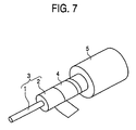
- a coaxial flexible piezoelectric cable of this kind is constituted by forming an outer electrode 4 at an outer surface of a piezoelectric tube 3 formed with a coaxial flexible piezoelectric member 2 at a surrounding of a core electrode 1 and forming a protective core layer 5 at a surrounding thereof.
- a flexible piezoelectric cable is generally polarized as follows.
- Reference 1 piezoelectric composite material comprising piezoelectric ceramic powder and synthetic rubber, Powder and Industry, Vol. 22, No. 1, pages 50-56, 1990 shows that the coaxial flexible piezoelectric member 2 is polarized by applying high voltage between the core electrode 1 and the outer electrode 4. This is disclosed also in USP 4,568,851. A direction of spontaneous polarization of a ceramic particle is aligned in a direction of an electric field by polarization and therefore, a piezoelectric property is provided to the coaxial flexible piezoelectric member 2. The polarization plays an important role in this respect.
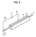
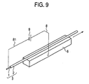
- a polarizing apparatus arranging the piezoelectric tube 3 formed with the coaxial piezoelectric member 2 at the surrounding of the core electrode 1 at a piezoelectric tube path portion 61 of a block-like conductor 6 and connecting direct current voltage generating means 9 between the block-like conductor 6 and the core electrode 1 via a lead wire 81 and a lead wire 82 to apply the direct current voltage.
- a polarizing apparatus directly arranging the piezoelectric tube 3 to the block-like conductor 6 and connecting the direct current voltage generating means 9 between the block-like conductor 6 and the core electrode 1 via a lead wire 8 and the lead wire 81 to apply direct current voltage.
- the coaxial flexible piezoelectric member 2 is arranged at the block-like conductor 6 or the piezoelectric tube path 61 of the block-like conductor 6 and therefore, the block-like conductor 6 is operated as an outer electrode. Therefore, a portion of the coaxial flexible piezoelectric member 2 arranged at the block-like conductor 6 can be polarized by applying direct current voltage between the block-like conductor 6 and the core electrode 1 by the direct current voltage generating means 9.
- the invention is for resolving the problem of the background art and it is an object thereof to provide a polarizing apparatus and a polarizing method of a coaxial flexible piezoelectric cable capable of moving the piezoelectric tube 3 by a small force.
- a path portion of a piezoelectric tube of a block-like conductor is provided with a recessed and projected portion for reducing a friction resistance.
- a polarizing apparatus of a coaxial flexible piezoelectric cable of the invention includes a path portion of a piezoelectric tube, the piezoelectric tube is arranged at a plurality of block-like conductors aligned in parallel and a plurality of pulleys arranged at fold back portions of the piezoelectric tube for moving the piezoelectric tube and, a direct current voltage is applied between the block-like conductor and a core electrode.
- dividing the block-like conductor by a plural number, a friction force between the path portion of the piezoelectric tube per divided one and the piezoelectric tube is reduced.
- the piezoelectric tube is made to be able to move by a small force by the plurality of pulleys arranged at the fold back portions of the piezoelectric tube.
- the invention provides a defect detecting apparatus of a coaxial flexible piezoelectric cable comprising inspecting electrode means having a hole arranged with a piezoelectric tube formed with a coaxial flexible piezoelectric member at a surrounding of a core electrode, moving means arranged after the inspecting electrode means for moving the piezoelectric tube and direct current voltage applying means connected to the inspecting electrode means and the core electrode.
- the coaxial flexible piezoelectric member is arranged at the hole of the inspecting electrode means and therefore, the inspecting electrode means is operated as an outer electrode. Therefore, a direct current voltage can be applied between the inspecting electrode means and the core electrode to apply on the coaxial flexible piezoelectric member by the direct current voltage applying means.
- coaxial flexible piezoelectric member to be inspected When a defect is present at a portion of the coaxial flexible piezoelectric member arranged at the hole of the inspecting electrode means (hereinafter referred to as coaxial flexible piezoelectric member to be inspected), small discharge is brought about at the defect portion. In accordance with the small discharge, a discharge current is made to flow or sound or light is emitted and therefore, presence of the defect can easily be detected. Therefore, presence of the defect at the coaxial flexible piezoelectric member to be inspected can be specified.
- the invention provides a defect detecting apparatus of a coaxial flexible piezoelectric cable, the defect detecting apparatus comprising inspecting electrode means having a hole arranged with a piezoelectric tube formed with a coaxial flexible piezoelectric member at a surrounding of a core electrode, moving means arranged after the inspecting electrode means for moving the piezoelectric tube and direct current voltage applying means connected to the inspecting electrode means and the core electrode.
- the inspecting electrode means is operated as an outer electrode. Therefore, a direct current voltage can be applied to the coaxial flexible piezoelectric member by the direct current voltage applying means between the inspecting electrode means and the core electrode.
- a defect is present at a portion of the coaxial flexible piezoelectric member arranged at the hole of the inspecting electrode means (hereinafter, referred to as coaxial flexible piezoelectric member to be inspected)
- small discharge is brought about at the defect portion.
- a discharge current is made to flow or sound or light is emitted and therefore, presence of the defect can easily be detected. Therefore, it can be specified that the defect is present at the coaxial flexible piezoelectric member to be inspected.
- a polarizing apparatus is a polarizing apparatus of a coaxial flexible piezoelectric cable, the polarizing apparatus comprising a block-like conductor in which a path portion of a piezoelectric tube formed with a coaxial flexible piezoelectric member at a surrounding of a core electrode includes a path portion in a recessed and projected shape and direct current voltage generating means connected to the block-like conductor and the core electrode.
- the piezoelectric tube By arranging the piezoelectric tube at the path portion of the block-like conductor, the block-like conductor is operated as an outer electrode. Therefore, by applying high voltage between the block-like conductor and the core electrode, a portion of the coaxial flexible piezoelectric member arranged with the block-like conductor can be polarized.
- the path portion of the piezoelectric tube of the block-like conductor is constituted by the recessed and the projected shape.
- the piezoelectric tube arranged at the block-like conductor is heated and temperature of the piezoelectric tube can be controlled and therefore, the coaxial flexible piezoelectric member can be polarized at necessary temperature.
- the polarizing apparatus according to Claim 3 is the polarizing apparatus of a coaxial flexible piezoelectric cable according to either one of Claims 1 and 2, wherein a metal net is arranged at the block-like conductor and the path portion of the piezoelectric tube is constituted by the metal net.
- a metal net is arranged at the block-like conductor and the path portion of the piezoelectric tube is constituted by the metal net.
- the polarizing apparatus according to Claim 4 is the polarizing apparatus of a coaxial flexible piezoelectric cable according to either one of Claims 1 and 2, wherein the block-like conductor is provided with a groove a surface of which is constituted by a recessed and projected shape and the portion of the piezoelectric tube to be arranged is constituted by the groove the surface of which is constituted by the recessed and projected shape.
- the block-like conductor is heated, the piezoelectric tube arranged at the groove of the block-like conductor is heated from a bottom face and two wall faces of the groove. Therefore, the piezoelectric tube is further uniformly heated and therefore, the coaxial flexible piezoelectric member can be polarized at necessary temperature. Further, an upper portion thereof is opened and the piezoelectric tube can simply be arranged from the upper portion of the groove.
- the polarizing apparatus according to Claim 5 is the polarizing apparatus of a coaxial flexible piezoelectric cable according to either one of Claims 1 and 2, wherein the block-like conductor is provided with a groove arranged with a metal net and the piezoelectric tube is arranged at the groove arranged with the metal net.
- the piezoelectric tube and the metal net are brought into contact with each other in a point-like shape. Therefore, the friction force between the piezoelectric tube and the face arranging the piezoelectric tube is reduced and the piezoelectric tube can be moved by a small force.
- the invention described in Claim 6 is a polarizing method of a coaxial flexible piezoelectric cable, wherein a piezoelectric tube is arranged at a path portion of a block-like conductor and a direct current voltage is applied between the block-like conductor and the core electrode. Therefore, the block-like conductor is operated as an outer electrode and therefore, by applying high voltage between the block-like conductor and the core electrode, a portion of the coaxial flexible piezoelectric member arranged at the block-like conductor and the path portion of the block-like conductor can be polarized.
- the path portion of the piezoelectric tube of the block-like conductor is constituted by a recessed and projected shape to reduce the friction resistance.
- the piezoelectric tube and the path portion of the piezoelectric tube are brought into contact with each other in a point-like shape. Therefore, the friction force between the piezoelectric tube and the face for arranging the piezoelectric tube is reduced and the piezoelectric tube can be moved by a small force. Further, the coaxial flexible piezoelectric member can be polarized by a necessary period of time by controlling a time period of stopping and moving the piezoelectric tube or a moving speed thereof.
- the invention described in Claim 7 is the polarizing method of a coaxial flexible piezoelectric cable according to Claim 2, wherein the block-like conductor is heated by a heating block arranged with a heater and the direct current voltage is applied between the core line of the piezoelectric tube and the block-like conductor while heating the piezoelectric tube arranged at the block-like conductor. Since the temperature of the piezoelectric tube can be controlled, the coaxial flexible piezoelectric member can be polarized at necessary temperature.
- a polarizing apparatus is a polarizing apparatus of a coaxial flexible piezoelectric cable, the polarizing apparatus comprising a plurality of block-like conductors each having a path portion of a piezoelectric tube formed with a coaxial flexible piezoelectric member at a surrounding of a core electrode and arranged in parallel, a plurality of pulleys arranged at fold back portions of the piezoelectric tube for moving the piezoelectric tube and direct current voltage generating means connected to the plurality of block-like conductors and the core electrode.
- the block-like conductor is operated as an outer electrode.
- the plurality of pulleys arranged at the fold back portions of the piezoelectric tube move the piezoelectric tube. Therefore, by applying high voltage between the block-like conductor and the core electrode, while moving a portion of the coaxial flexible piezoelectric member arranged at the block-like conductor or repeating to move and stop the coaxial flexible piezoelectric member, the coaxial flexible piezoelectric member can be polarized.
- the friction force between the path portion of the piezoelectric tube per divided one and the piezoelectric tube is reduced. Further, the piezoelectric tube can be moved by a small force by the plurality of pulleys arranged at the fold back portions of the piezoelectric tube.
- the polarizing apparatus comprises the plurality of pulleys having the same diameter and successively retarded rotational numbers and the piezoelectric tube is moved by the plurality of pulleys arranged at the fold back portions of the piezoelectric tube. Further, since the speed of moving the piezoelectric tube is successively retarded, the coaxial flexible piezoelectric member can be polarized without pulling portions of the piezoelectric tube to each other by a difference of elongations of the portions of the piezoelectric tube or by a slight difference between the rotational numbers of the pulleys in addition to the constitution according to Claim 11.
- the polarizing apparatus according to Claim 13 comprises a plurality of pulleys having the same rotational number and successively reduced diameters in addition to the constitution according to Claim 11 for moving the piezoelectric tube by the pulleys arranged at the fold back portions of the piezoelectric tube. Further, the speed of moving the piezoelectric tube is successively retarded and therefore, the coaxial flexible piezoelectric member can be polarized without pulling portions of the piezoelectric tube to each other by a difference of elongations of the portions of the piezoelectric tube or by a slight difference between the diameters of the pulleys.
- the coaxial flexible piezoelectric member is arranged at a hole of inspecting electrode means and therefore, the inspecting electrode means is operated as an outer electrode. Therefore, a direct current voltage can be applied on the coaxial flexible piezoelectric member between the inspecting electrode means and the core electrode by the direct current voltage applying means.
- the inspecting electrode means is constituted by a metal.
- a metal is provided with a low electric resistance and easy to work and therefore, the metal is suitable for the inspecting electrode means.
- the detecting electrode means is constituted by graphite.
- Graphite is provided with conductivity and is of low friction performance and therefore, the coaxial flexible piezoelectric member can smoothly be moved.
- a pole of the direct current voltage applying means connected to the core electrode is maintained at a ground potential. Therefore, even when the human body is brought into contact with the core electrode, safety can be maintained without being electrified.
- the defect detecting apparatus of a coaxial flexible piezoelectric cable according to Claim 18, when the piezoelectric tube is arranged at a hole provided at the conductor constituting the inspecting electrode means, a direct current voltage is applied between the core line of the piezoelectric tube and the inspecting electrode means.
- the direct current voltage can be applied between the core line and the inspecting electrode means and therefore, the defect can continuously be detected.
- the defect detecting apparatus of a coaxial flexible piezoelectric cable according to Claim 19 is arranged with marking means.
- marking means When small discharge is brought about at the defect portion, the coaxial flexible piezoelectric member can be marked by operating the marking means.
- a distance between the inspecting electrode means and the marking means By specifying a distance between the inspecting electrode means and the marking means, a portion at which the defect is present can be specified.
- the defect portion of the coaxial flexible piezoelectric member can be marked. That is, when the defect portion of the coaxial flexible piezoelectric member to be inspected at which small discharge is brought about is moved from the inspecting electrode means to a position of the marking means, the defect portion of the coaxial flexible piezoelectric member can be marked by operating the marking means.
- the marking means is a clamp apparatus.
- the coaxial flexible piezoelectric member is deformed by being pressed by the clamp apparatus. Therefore, a portion at which the defect is present can clearly be determined.
- the clamp apparatus of the marking means is provided with a heater.
- the defect portion of the coaxial flexible piezoelectric member to be inspected is heated simultaneously with being pressed by the clamp apparatus, a resin included in the coaxial flexible piezoelectric member is softened and the pressed and heated portion is easily deformed. Therefore, a portion at which the defect is present can clearly be determined.
- the marking means is a laser heating apparatus. A laser-irradiated portion of the defect portion of the coaxial flexible piezoelectric member to be inspected is melted by being heated by the laser heating apparatus. Therefore, a portion at which the defect is present can clearly be determined.
- the marking means is a hot wind heating apparatus. A heated portion of the defect portion of the coaxial flexible piezoelectric member to be inspected heated by the hot wind heating apparatus is melted. Therefore, the portion at which the defect is present can clearly de determined.
- the defect inspecting apparatus of a coaxial flexible piezoelectric cable according to Claim 24, by providing current detecting means provided between the core electrode or the inspecting electrode means and the direct current voltage applying means, a portion at which the defect is present can clearly be determined.
- the defect detecting apparatus of a coaxial flexible piezoelectric cable according to Claim 25, when the piezoelectric tube is arranged at a hole provided at the conductor constituting the inspecting electrode means, a direct current voltage is applied between the core line of the piezoelectric tube and the inspecting electrode means. When the piezoelectric tube is stopped or moved by moving means, the direct current voltage can be applied between the core line and the detecting electrode means and therefore, the defect can continuously be detected.
- defect detecting apparatus of a coaxial flexible piezoelectric cable according to Claim 26, when current is detected to flow by a predetermined value or higher by the current detecting means, a mark is attached to a surface of the piezoelectric tube by operating the marking means. Therefore, defect detecting operation of the coaxial flexible piezoelectric cable can continuously be carried out automatically.
- notation 1 designates a core electrode
- notation 2 designates a coaxial flexible piezoelectric member
- notation 3 designates a piezoelectric tube
- notation 4 designates an outer electrode
- notation 5 designates a protective cover layer
- notation 6 designates a conductor block
- notation 61 designates a piezoelectric tube path portion
- notation 62 designates a recessed and projected shape
- notation 7 designates a heater
- notation 71 designates a heating block
- notation 72 designates an insulating sheet
- notation 73 designates an insulating member
- notations, 8, 81, 82 designate lead wires
- notation 9 designates direct current voltage generating means
- notation 10 designates a metal net
- notation 11 designates a groove
- notations 17, 17a, 17b designate pulleys
- notation 171 designates a groove of a pulley
- notation 260 designates inspecting electrode means
- notation 261
- Fig. 1 is an outlook view showing a constitution of a coaxial flexible piezoelectric polarizing apparatus according to Embodiment 1 of the invention.
- the coaxial flexible piezoelectric member 2 is formed for the core electrode 1.
- the molded member is referred to as the piezoelectric tube 3.
- As the core electrode 1 a coil-like metal line, a line bundled with metal slender lines or the like is used.
- As the flexible piezoelectric member 2 a composite piezoelectric member of a polymer base material of epoxy resin, urethane resin, chloroprene resin, chlorinated polyethylene resin or the like added with a ceramic piezoelectric powder of titanate zirconate lead or a polymer piezoelectric member of PVDF or the like is used.
- the piezoelectric tube 3 is arranged to the piezoelectric tube path portion 61 provided at the block-like conductor 6 and the piezoelectric tube 3 is moved by moving means (not illustrated).
- the piezoelectric tube path portion 61 is constituted by a recessed and projected shape.
- the block-like conductor 6 is provided with a width of 30 millimeters, a height of 20 millimeters and a length of 5000 millimeters.
- Recesses and projections of the piezoelectric tube path portion 61 are provided with a recess depth of 0.5mm, a recess width of 1.5mm, and a projection width of 1mm. That is, recesses and projections are continuously worked by a pitch of 2.5mm.
- Recesses and projections of the piezoelectric tube path portion 61 may be constituted by knurling meshes of plane meshes, checker meshes or the like since it is an object thereof to reduce an area in contact with the piezoelectric tube 3.
- moving means not illustrated
- the piezoelectric tube 3 is reeled by a reeling drum and the piezoelectric tube 3 is moved by rotating the reeling drum. Further, a direction of moving the piezoelectric tube 3 arranged at the block-like conductor 6 is indicated by an arrow mark.
- Temperature in polarizing the coaxial flexible piezoelectric member 2 generally needs to be equal to or higher than temperature of using the coaxial flexible piezoelectric member 2 and polarization is carried out while maintaining the coaxial flexible piezoelectric member 2 at necessary temperature. Since the coaxial flexible piezoelectric member 2 is brought into contact with recesses and projections of the piezoelectric tube path portion 61, by heating the block-like conductor 6, the coaxial flexible piezoelectric member 2 can be heated to necessary temperature. In order to heat the block-like conductor 6 to necessary temperature, the heating block 71 arranged with the heater 7 is used and the block-like conductor 6 is heated to arbitrary temperature via the insulating sheet 72.
- the insulating sheet 72 mica having a thickness of 0.5 millimeter is used, there may be used an electrically insulating material of polyimide, poly-tetrafluoroethylene, polyethyleneterephthalate (abbreviated as PET), silicone rubber or the like.
- the block-like conductor 6 and the lead wire 8 are electrically connected and the lead wire 8 is electrically connected to a positive pole or a negative pole of the direct current voltage generating means 9. Further, the core electrode 1 and the lead wire 81 are electrically connected and the lead wire 81 is connected to other electrode of the direct current voltage generating means 9.
- high voltage is applied between the core electrode 1 and the block-like conductor 6 by the direct current voltage generating means 9 to thereby polarize the coaxial flexible piezoelectric member 2.
- high voltage of 5 through 10 kV/mm is applied between the core electrode 1 and the block-like conductor 6.
- polarization of the piezoelectric tube 3 is carried out at temperature of 120°C and by applied voltage of 8kV/mm.
- the piezoelectric tube path portion 61 is constituted by the recessed and projected shape to alleviate friction resistance.
- the piezoelectric tube 3 is brought into contact with only projection of recesses and projections.
- the force of attracting the coaxial flexible piezoelectric member 2 and the piezoelectric tube path portion 61 to each other by the electrostatic force is in proportion to an area of projections.
- the friction force in moving the piezoelectric tube 3 is in proportion to the force of attracting the coaxial flexible piezoelectric member 2 and the piezoelectric tube path portion 61 to each other. That is, by the recesses and projections, the friction force between the piezoelectric tube 3 and the piezoelectric tube path portion 61 can be reduced and the piezoelectric tube 3 can be moved by small force.
- Fig. 2 is an outlook view showing a constitution of a coaxial flexible piezoelectric polarizing apparatus according to Embodiment 2 of the invention.
- the piezoelectric tube path portion is constituted by the metal net 10.
- the piezoelectric tube 3 is arranged at the metal net 10 provided on a face of the block-like conductor 6 and is moved by moving means (not illustrated).
- a surface of the metal net 10 is constituted by a recessed and projected shape.
- the friction force between the piezoelectric tube 3 and the piezoelectric tube path portion (the metal net 10 according to Embodiment 2) without working a surface for arranging the piezoelectric tube 3 in a recessed and projected shape and the piezoelectric tube 3 can be moved by a small force.
- the metal net 10 a conductor of iron, stainless steel, copper, brass, aluminum or the like is used.
- the material of the metal net 10 there is used stainless steel which is easily available and having corrosion resistance performance.
- a net of stainless steel having a wire diameter of 0.2 millimeter and a mesh of 50.
- Fig. 3 is an outlook view showing a constitution of a coaxial flexible piezoelectric polarizing apparatus according to Embodiment 4 of the invention.
- the polarizing apparatus is constituted by providing the groove 11 at the block-like conductor 6, constituting the path portion of the piezoelectric tube 3 by the groove 11 and constituting an inner face of the groove 11 by the recessed and projected shape 62.
- the piezoelectric tube 3 arranged at the groove 11 of the block-like conductor 6 is heated by heating the block-like conductor 6, the piezoelectric tube 3 is heated from a bottom face and two wall faces of the groove 11. Therefore, the piezoelectric tube 3 is further uniformly heated and therefore, the coaxial flexible piezoelectric member 2 can be polarized at necessary temperature.
- the piezoelectric tube 3 can simply be arranged from the upper portion of the groove 11. Further, since the inner face of the groove 11 constituting the path portion of the piezoelectric tube 3 is constituted by the recessed and projected shape 62, the piezoelectric tube 3 is brought into contact with only projections of recesses and projections and therefore, the piezoelectric tube 3 can be moved by a small force.
- the groove 1 can be constituted by any shape of a polygonal shape (triangular shape, quadrangular shape, pentagonal shape, hexagonal shape or the like), U-like shape or the like so far as the shape can arrange the piezoelectric tube 3. In working the groove 11, cutting, discharging extrusion or the like is used.
- a method of directly forming the inner face of the groove 11 by using cutting, discharging, pressing or the like and a method of arranging a conductive member formed with recesses and projections (metal net, punching sheet, pressed sheet formed with recessed and projected shape or the like) at the groove 11.
- the shape of the groove 11 is constituted by a U-like shape such that the groove 11 can simply be worked by an end mill and a net of stainless steel is arranged at the inner face of the U-like shape, that is, to form the recessed and projected shape 62. Further, in Fig. 3, a direction of moving the piezoelectric tube 3 arranged at the block-like conductor 6 is indicated by an arrow mark.
- Fig. 4 is an outlook view showing a constitution of a coaxial flexible piezoelectric polarizing apparatus according to a fourth embodiment.
- the coaxial flexible piezoelectric member 2 is formed for the core electrode 1.
- the molded body is referred to as the piezoelectric tube 3.
- As the core electrode 1 a coil-like metal line or a line bundled with metal slender lines or the like is used.
- As the coaxial flexible piezoelectric member 2 a composite piezoelectric member of a polymer base metal of epoxy resin, urethane resin, chloroprene resin, chlorinated polyethylene or the like added with a ceramic piezoelectric powder of titanate zirconate lead or a polymer piezoelectric member of PVDF or the like is used.
- a plurality of pieces (4 pieces according to the embodiment) of the block-like conductors 6 are arranged in parallel.
- the block-like conductor 6 is provided with a groove of the piezoelectric tube path portion 61 and a conductor of iron, stainless steel, copper, brass, aluminum, graphite or the like is used for a material thereof.
- the piezoelectric tube path portion 61 is formed by cutting, discharging, forging for the like.
- the material of the block-like conductor 6 there is used aluminum which is easily available and is easy to work.
- the piezoelectric tube path portion 61 is constituted by a groove width of 3 millimeters and a groove depth of 7 millimeters and the block-like conductor 6 is constituted by a width of 30 millimeters and a height of 20 millimeters and a length of 1000 millimeters.
- the pulley 17 is provided at a fold back portion (at 3 locations according to the embodiment) of the piezoelectric tube 3 and is driven by a pulley driving apparatus 173.
- the pulley 17 is provided with the groove 171.
- the groove 171 is constituted by a V-like shape or a U-like shape and the piezoelectric tube 3 is made to wrap thereon.
- Heating of the piezoelectric tube 3 is carried out indirectly by heating the block-like conductor 6.
- the heating block 71 arranged with the heater 7 is used to heat the block-like conductor 6 to arbitrary temperature via the insulating sheet 72.
- the insulating sheet 72 a mica plate having a thickness of 0.5 millimeter is used.
- a lower face of the heating block 71 is provided with the insulating member 73 to efficiently conduct heat to the block-like conductor 6 at the upper face of the heating block.
- Each of the block-like conductors 6 and one side of the lead wire 81 are electrically connected and other side of the lead wire 81 is electrically connected to a positive pole or a negative pole of the direct current voltage generating means 9. Further, the core electrode 1 and one side of the lead wire 82 are electrically connected and other side of the lead wire 82 is electrically connected to other pole of the direct current voltage generating means 9.
- the piezoelectric tube 3 is arranged successively to the piezoelectric tube path portion 61 provided at the block-like conductor 6 and the groove 171 of the pulley 17, each pulley 17 is driven by the pulley driving apparatus 173, and each pulley 17 is rotated in an arrow mark 172 direction. Further, the piezoelectric tube 3 is drawn from an arrow mark 100 direction, and the piezoelectric tube 3 is moved in an arrow mark 101 direction by drawing means (not illustrated).
- the coaxial flexible piezoelectric member 2 is brought into contact with a wall face of the piezoelectric tube path portion 61 in the U-like shape and therefore, by heating the block-like conductor 6, the coaxial flexible piezoelectric member 2 can be heated to necessary temperature. Specifically, polarization is carried out at temperature of the piezoelectric tube 3 of 120°C.
- a plurality of pieces (4 pieces according to the embodiment) of the block-like conductors 6 provided with the piezoelectric tube path portions 61 are used to reduce the friction resistance with the coaxial flexible piezoelectric member 2 when moved in the piezoelectric tube path portions 61.
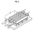
- Fig. 5 is an outlook view showing a constitution of a coaxial flexible piezoelectric polarizing apparatus according to a fifth embodiment.
- the pulleys 17a, 17b and 17c are provided with the same diameter and different rotational numbers.
- the rotational number of the pulley 17a, the rotational number of the pulley 17b and the rotational number of the pulley 17c are successively reduced little by little.
- a drawing speed V2 of the piezoelectric tube 3 by drawing means (not illustrated) is made to be slightly slower than a feeding speed of the piezoelectric tube 3.
- the apparatus of Embodiment 5 is the same as the apparatus of Embodiment 4 except that the rotational numbers of the pulleys 17a, 17b and 17c are successively reduced.
- the piezoelectric tube 3 is moved by the pulleys 17a, 17b and 17c arranged at fold back portions of the piezoelectric tube 3. Further, since the speed of moving the piezoelectric tube 3 by the pulleys 17a, 17b and 17c is successively retarded, portions of the piezoelectric tube 3 are not pulled by each other by a difference between elongations of the portions of the piezoelectric tube 3 or by a slight difference between the rotational numbers of the pulleys.
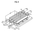
- Fig. 6 is an outlook view showing a constitution of a coaxial flexible piezoelectric polarizing apparatus according to a sixth embodiment of the invention.
- the pulleys 17a, 17b and 17c are provided with the same rotational number and different diameters.
- the diameter of the pulley 17a, the diameter of the pulley 17b and the diameter of the pulley 17c are successively reduced little by little.
- the drawing speed V2 of the piezoelectric tube 3 by drawing means (not illustrated) is made to be slower than the feeding speed of the piezoelectric tube 3 by the pulley 17c.
- the apparatus of Embodiment 6 is the same as the apparatus of Embodiment 1 except that the diameters of the pulleys 17a, 17b and 17c are successively reduced.
- the piezoelectric tube 3 is moved by the pulleys 17a, 17b and 17c arranged at fold back portions of the piezoelectric tube 3. Further, since speeds of moving the piezoelectric tube 3 by the pulleys 17a, 17b and 17c are successively retarded, portions of the piezoelectric tube 3 are not pulled by each other by a difference of elongations of the portions of the piezoelectric tube 3 or by a slight difference between the rotational numbers of the pulleys.
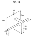
- Fig. 10 is an outlook view showing a constitution of a defect detecting apparatus of the coaxial flexible piezoelectric member 2 according to Embodiment 7 of the invention.
- the piezoelectric tube 3 is constituted by forming the coaxial flexible piezoelectric member 2 for the core electrode 1.
- the core electrode a coil-like metal line or a line bundled with metal slender lines or the like is used.
- the flexible piezoelectric member 2 there is used a composite piezoelectric member of a polymer base material of epoxy resin, urethane resin, chloroprene resin, chlorinated polyethylene resin or the like added with a ceramic piezoelectric powder of titanate zirconate lead or a polymer piezoelectric member of PVDF or the like.
- the piezoelectric tube 3 is moved by moving means (not illustrated) by way of the inspecting electrode means 260.
- an outer peripheral face of the coaxial flexible piezoelectric member 2 is arranged at the hole 261 of the inspecting electrode means 260.
- the inspecting electrode means 260 is connected to one pole of the direct current voltage generating means 280 via the lead wire 270 and the core electrode 1 is connected to other pole of the direct current voltage generating means 280 via the lead wire 271, respectively.
- a direction of moving the piezoelectric tube 3 arranged at the hole 261 of the inspecting electrode means 260 is indicated by an arrow mark.
- An inner diameter dimension of the hole 261 is slightly larger than an outer diameter dimension of the piezoelectric tube 3. According to the embodiment, a diameter of the hole 261 is made to be 2.2millimeters in contrast to the piezoelectric tube 3 having the outer diameter of 1.8 millimeters.
- Direct current voltage is applied between the inspecting electrode means 260 and the core electrode 1 by the direct current voltage applying means 280 to apply on the coaxial flexible piezoelectric member to be inspected.
- a voltage of 4 kV is applied thereto.
- any of the inspecting electrode means 260 can be used so far as the inspecting electrode means 260 is a conductor.
- a metal which is easily available and easy to work copper, aluminum, brass, iron, stainless steel or the like
- graphite is also preferable. Similar to a metal, graphite is easily available and easy to work. Further, graphite is provided with not only conductivity but also small friction resistance. That is, when the piezoelectric tube 260 is moved by moving means (not illustrated), the piezoelectric tube 260 can be moved by a smaller force.
- the inspecting electrode means 260 In order to ensure safety of defect inspecting operation, it is preferable to connect the inspecting electrode means 260 to a positive pole or a negative pole of the direct current voltage applying means 280 and connect the core electrode 11 to the ground. Since direct current voltage portions are limited to the inspecting electrode means 260 and the lead wire 270 and the like and therefore, by isolating only the portions from an outer field, a possibility of bringing the human body into contact with the direct current voltage portions can easily be reduced. On the other hand, when the core electrode 1 is connected to a positive pole or a negative pole of the direct current voltage applying means 8, the core electrode 1 is maintained at high voltage and therefore, the direct current voltage portions are present at a total of the defect inspecting apparatus. Therefore, the possibility of bringing the human body into contact with the high voltage portion is enhanced.
- Fig. 11 is an outlook view showing a constitution of a defect detecting apparatus of the coaxial flexible piezoelectric member 2 according to Embodiment 8 of the invention.
- the marking means 290 is arranged before or after the inspecting electrode means 260.
- a defect is detected by discharge current or sound or light in accordance with small discharge brought about at the defect portion, by operating the marking means, a portion before or after the defect portion of the coaxial flexible piezoelectric member to be inspected can be marked. Further, therefore, the portion at which the defect is present can clearly be specified.
- the defect portion of the coaxial flexible piezoelectric member 2 can be marked. That is, the defect portion of the coaxial flexible piezoelectric member can be marked by operating the marking means when the defect portion of the coaxial flexible piezoelectric member to be inspected at which small discharge is brought about is moved from the inspecting electrode means 260 to a position of the marking means 290.
- Fig. 12 is an outlook view showing a constitution of a defect detecting apparatus of the coaxial flexible piezoelectric member 2 according to Embodiment 9 of the invention.
- the marking means 290 is the clamp apparatus 310.
- the coaxial flexible piezoelectric member 2 is deformed by being clamped by the clamp apparatus 310 to press. Therefore, the portion at which the effect is present can clearly be determined.
- the clamp apparatus 310 is constituted by a structure of clamping the coaxial flexible piezoelectric member 2 by the clamp metal piece 301 and the clamp metal piece 302 by utilizing hydraulic pressure or electricity as power.
- a clamping force may be a force of deforming the coaxial flexible piezoelectric member 2. According to the embodiment, clamping is carried out by a force of 5 newtons.
- the clamp apparatus 310 is arranged before or after the inspecting electrode means 260.
- the defect portion of the coaxial flexible piezoelectric member 2 can be marked. That is, when the defect portion of the coaxial flexible piezoelectric member to be inspected at which small discharge is brought about is moved from the inspecting electrode means 260 to the position of the clamp apparatus 310, the defect portion of the coaxial flexible piezoelectric member can be marked by operating the clamp apparatus 310.
- Fig. 13 is an outlook view showing a constitution of a defect detecting apparatus of the coaxial flexible piezoelectric member 2 according to Embodiment 10 of the invention.
- the marking means 290 is the clamp apparatus 310 having the heater 311.
- the coaxial flexible piezoelectric member 2 is clamped by the clamp apparatus 310, the coaxial flexible piezoelectric member 2 is deformed by being heated simultaneously.
- the resin included in the coaxial flexible piezoelectric member 2 is softened and a pressed and heated portion is easily deformed. Therefore, a portion at which the defect is present can clearly be determined.
- the clamp apparatus 310 is constituted by a structure of clamping the coaxial flexible piezoelectric member 2 by the clamp metal piece 301 and the clamp metal piece 302 by utilizing air, hydraulic pressure or electricity as power.
- the clamping force may be a force of deforming the coaxial flexible piezoelectric member 2.
- the coaxial flexible piezoelectric member 2 is clamped by a force of 2 newtons.
- the clamp apparatus 310 is arranged before or after the inspecting electrode means 160. When a defect is detected by discharge current or sound or light in accordance with small discharge brought about at the defect portion, a portion of the coaxial flexible piezoelectric member to be inspected before or after the defect portion can be marked by operating the clamp apparatus 310. Therefore, a portion at which the defect is present can clearly be determined.
- the defect portion of the coaxial flexible piezoelectric member 2 can be marked by arranging the clamp apparatus 310 after the inspecting electrode means 260. That is, when the defect portion of the coaxial flexible piezoelectric member to be inspected at which small discharge is brought about is moved from the inspecting electrode means 260 to a position of the clamp apparatus 310, the defect portion of the coaxial flexible piezoelectric member can be marked by operating the clamp apparatus 320.
- Fig. 14 is an outlook view showing a constitution of a defect detecting apparatus of the coaxial flexible piezoelectric member 2 according to Embodiment 11 of the invention.
- the marking means 290 is the laser heating apparatus 312.
- the coaxial flexible piezoelectric member 2 is melted by being heated by the laser heating apparatus 312. Therefore, the portion at which the defect is present can clearly be determined.
- the laser heating apparatus 312 a carbon dioxide gas laser or a YAG laser apparatus which is generally used for industry is used.
- the laser beam 321 is irradiated to the coaxial flexible piezoelectric member 2.
- the laser heating apparatus 312 is arranged before or after the inspecting electrode means 260. By discharge current or sound or light in accordance with small discharge brought about at the defect portion, when the defect is detected, a portion of the coaxial flexible piezoelectric member to be inspected before or after the detect portion can be marked by operating the laser heating apparatus 312. Therefore, the portion at which the defect is present can clearly be specified.
- the defect portion of the coaxial flexible piezoelectric member 2 can be marked. That is, when the defect portion of the coaxial flexible piezoelectric member to be inspected at which small discharge is brought about is moved from the inspecting electrode means 260 to a position of the laser heating apparatus 312, the defect portion of the coaxial flexible piezoelectric member can be marked by operating the laser heating apparatus 312.
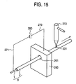
- Fig. 15 is an outlook view showing a constitution of a defect detecting apparatus of the coaxial flexible piezoelectric member 2 according to Embodiment 12 of the invention.
- the marking means 290 is the hot wind heating apparatus 313.
- the coaxial flexible piezoelectric member 2 is melted by being heated by the hot wind heating apparatus 313. Therefore, the portion at which the defect is present can clearly be determined.
- the hot wind 331 blown from the hot wind heating apparatus 313 is injected to the coaxial flexible piezoelectric member 2.
- the hot wind heating apparatus 313 is arranged before or after the detecting electrode means 260. By discharge current or sound or light in accordance with small discharge brought about at the defect portion, when the defect is detected, a portion of the coaxial flexible piezoelectric member to be inspected before or after the defect portion can be marked by operating the hot wind heating apparatus 313. Therefore, the portion at which the defect is present can clearly be specified.
- the defect portion of the coaxial flexible piezoelectric member 2 can be marked. That is, when the defect portion of the coaxial flexible piezoelectric member to be inspected at which small discharge is brought about is moved from the inspecting electrode means 260 to a position of the hot wind heating apparatus 313, the defect portion of the coaxial flexible piezoelectric member can be marked by operating the hot wind heating apparatus 313.
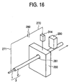
- Fig. 16 is an outlook view showing a constitution of a defect detecting apparatus of the coaxial flexible piezoelectric member 2 according to Embodiment 13 of the invention.
- the current detecting means 313 is provided between the core electrode 1 and the direct current voltage applying means 280 or between the inspecting electrode means 260 and the direct current voltage applying means 280.
- the marking means 290 is operated in correspondence with the current detecting means 314.
- the making means 290 can be operated. Therefore, when discharge is brought about, the surface of the flexible piezoelectric member 2 can be marked by the marking means 290. Thereby, a range in which the effect is present can automatically be specified.
- the defect portion of the coaxial flexible piezoelectric member 2 can be marked. That is, when the defect portion of the coaxial flexible piezoelectric member to be inspected at which small discharge is brought about is moved from the inspecting electrode means 260 to a position of the marking means 290, the defect portion of the coaxial flexible piezoelectric member can be marked by operating the making means 290.
- the path portion of the piezoelectric tube of the block-like conductor is provided with recesses and projections for reducing the friction resistance and therefore, by the recesses and projections, the friction force between the piezoelectric tube and the path portion of the piezoelectric tube is reduced and the piezoelectric tube can be moved by a small force.
- the friction force between the piezoelectric tube and the path portion of the piezoelectric tube is reduced and the piezoelectric tube can be moved by a small force. Therefore, when the piezoelectric tube is pulled to move, the piezoelectric tube is not elongated or broken and a highly reliable polarizing method can be provided.
- the friction force between the path portion of the piezoelectric tube of the block-like conductor per divided one and the piezoelectric tube can be reduced. Further, the piezoelectric tube can be moved by a small force by the plurality of pulleys arranged at fold back portions of the piezoelectric tube.
- the coaxial flexible piezoelectric member can be polarized without pulling portions of the piezoelectric tube to each other by a difference of elongation of the portions of the piezoelectric tube or a slight difference between rotational numbers of the pulleys.
- Japanese Patent Application No. 2001-234553 Japanese Patent Application No. 2001-234554, Japanese Patent Application No. 2001-234555
- Japanese Patent Application filed on December 14, 2001 Japanese Patent Application No. 2001-381350
Landscapes
- Engineering & Computer Science (AREA)
- Manufacturing & Machinery (AREA)
- Physics & Mathematics (AREA)
- General Physics & Mathematics (AREA)
- Investigating Or Analyzing Materials By The Use Of Ultrasonic Waves (AREA)
Abstract
The invention provides a defect inspecting
apparatus and a defect detecting method for specifying a
position of a defect before polarization when the defect is
included in a coaxial flexible piezoelectric member.
Further, when a piezoelectric tube is moved in
polarization, a friction force is produced between the
coaxial flexible piezoelectric member and a block-like
conductor and therefore, a large force is needed in moving
the piezoelectric tube. The invention provides a
polarizing apparatus and a polarizing method capable of
moving the piezoelectric tube even by a small force.
There are provided a defect detecting apparatus of
a coaxial flexible piezoelectric member having a
constitution of applying a direct current to a coaxial
flexible piezoelectric member while moving a piezoelectric
tube arranged at a hole of inspecting electrode means and a
marking apparatus for marking a defect portion. Thereby,
when a defect is present at a portion thereof arranged at
the hole of the inspecting electrode means, electricity is
discharged at the defect portion and therefore, the defect
portion can be specified and the mark can be attached to
the defect portion. Further, a conductive block provided
with a path portion of the piezoelectric tube is divided.
By dividing the block-like conductor by a plural number, a
friction force between the block-like conductor per divided
one and the piezoelectric tube is reduced. Further, the
piezoelectric tube can be moved by a small force by a
pulley arranged at a fold back portion of the piezoelectric
tube.
Description
The present invention relates to polarization of a
coaxial flexible piezoelectric cable. Further, the
invention relates to a defect detecting apparatus and a
defect detecting method of the cable.
In a background art, as shown by Fig. 7, a coaxial
flexible piezoelectric cable of this kind is constituted by
forming an outer electrode 4 at an outer surface of a
piezoelectric tube 3 formed with a coaxial flexible
piezoelectric member 2 at a surrounding of a core electrode
1 and forming a protective core layer 5 at a surrounding
thereof.
A flexible piezoelectric cable is generally
polarized as follows.
Reference 1 (Piezoelectric composite material
comprising piezoelectric ceramic powder and synthetic
rubber, Powder and Industry, Vol. 22, No. 1, pages 50-56,
1990) shows that the coaxial flexible piezoelectric member
2 is polarized by applying high voltage between the core
electrode 1 and the outer electrode 4. This is disclosed
also in USP 4,568,851. A direction of spontaneous
polarization of a ceramic particle is aligned in a
direction of an electric field by polarization and
therefore, a piezoelectric property is provided to the
coaxial flexible piezoelectric member 2. The polarization
plays an important role in this respect.
However, according to the above-described method,
when high voltage is applied between the core electrode 1
and the outer electrode 4, a defect of a small crack, a
clearance or the like is present in the coaxial flexible
piezoelectric member 2. As a result, high voltage cannot
be applied between the core electrode 1 and the outer
electrode 4 and therefore, the coaxial flexible
piezoelectric member 2 (normally having a length of several
hundreds m or more) cannot be polarized. Further, presence
of the defect cannot be detected until high voltage is
applied between the core electrode 1 and the outer
electrode 4, in other words, until finishing the coaxial
flexible piezoelectric cable except polarization and
therefore, fabrication thereof becomes unstable and yield
is deteriorated. Therefore, it has been desired to specify
a position at which the defect is present before
polarization.
Therefore, the following polarizing methods are
conceivable for the flexible piezoelectric cable.
As shown by Fig. 8, there is conceivable a
polarizing apparatus arranging the piezoelectric tube 3
formed with the coaxial piezoelectric member 2 at the
surrounding of the core electrode 1 at a piezoelectric tube
path portion 61 of a block-like conductor 6 and connecting
direct current voltage generating means 9 between the
block-like conductor 6 and the core electrode 1 via a lead
wire 81 and a lead wire 82 to apply the direct current
voltage. Or, as shown by Fig. 9, there is conceivable a
polarizing apparatus directly arranging the piezoelectric
tube 3 to the block-like conductor 6 and connecting the
direct current voltage generating means 9 between the
block-like conductor 6 and the core electrode 1 via a lead
wire 8 and the lead wire 81 to apply direct current
voltage. According to the polarizing apparatus, the
coaxial flexible piezoelectric member 2 is arranged at the
block-like conductor 6 or the piezoelectric tube path 61 of
the block-like conductor 6 and therefore, the block-like
conductor 6 is operated as an outer electrode. Therefore,
a portion of the coaxial flexible piezoelectric member 2
arranged at the block-like conductor 6 can be polarized by
applying direct current voltage between the block-like
conductor 6 and the core electrode 1 by the direct current
voltage generating means 9.
However, according to the method of the related
art, the following problem is posed.
When direct current voltage is applied between the
block-like conductor 6 and the core electrode 1 by the
direct current voltage generating means 9, a force of
attracting the coaxial flexible piezoelectric member 2 and
the block-like conductor 6 to each other is generated by an
electrostatic force. Therefore, when the piezoelectric
tube 3 is moved, a friction force is generated between the
coaxial flexible piezoelectric member 2 and the block-like
conductor 6 and the piezoelectric tube 3 cannot be moved or
even when the piezoelectric tube 3 can be moved, a large
force is needed.
The invention is for resolving the problem of the
background art and it is an object thereof to provide a
polarizing apparatus and a polarizing method of a coaxial
flexible piezoelectric cable capable of moving the
piezoelectric tube 3 by a small force.
Further, it is an object of the invention to
provide a defect detecting apparatus and a defect detecting
method for specifying a defect of a coaxial flexible
piezoelectric cable before polarization.
In order to resolve the problem of the background
art, according to a polarizing apparatus of a coaxial
flexible piezoelectric cable of the invention, a path
portion of a piezoelectric tube of a block-like conductor
is provided with a recessed and projected portion for
reducing a friction resistance. By the recesses and
projections, a friction force between the piezoelectric
tube and the path portion of the piezoelectric tube is
reduced and the piezoelectric tube is made to be able to
move by a small force.
Further, in order to resolve the problem of the
related art, a polarizing apparatus of a coaxial flexible
piezoelectric cable of the invention includes a path
portion of a piezoelectric tube, the piezoelectric tube is
arranged at a plurality of block-like conductors aligned in
parallel and a plurality of pulleys arranged at fold back
portions of the piezoelectric tube for moving the
piezoelectric tube and, a direct current voltage is applied
between the block-like conductor and a core electrode. By
dividing the block-like conductor by a plural number, a
friction force between the path portion of the
piezoelectric tube per divided one and the piezoelectric
tube is reduced. Further, the piezoelectric tube is made
to be able to move by a small force by the plurality of
pulleys arranged at the fold back portions of the
piezoelectric tube.
Further, in order to resolve the problem of the
related art, the invention provides a defect detecting
apparatus of a coaxial flexible piezoelectric cable
comprising inspecting electrode means having a hole
arranged with a piezoelectric tube formed with a coaxial
flexible piezoelectric member at a surrounding of a core
electrode, moving means arranged after the inspecting
electrode means for moving the piezoelectric tube and
direct current voltage applying means connected to the
inspecting electrode means and the core electrode.
According to the invention, the coaxial flexible
piezoelectric member is arranged at the hole of the
inspecting electrode means and therefore, the inspecting
electrode means is operated as an outer electrode.
Therefore, a direct current voltage can be applied between
the inspecting electrode means and the core electrode to
apply on the coaxial flexible piezoelectric member by the
direct current voltage applying means. When a defect is
present at a portion of the coaxial flexible piezoelectric
member arranged at the hole of the inspecting electrode
means (hereinafter referred to as coaxial flexible
piezoelectric member to be inspected), small discharge is
brought about at the defect portion. In accordance with
the small discharge, a discharge current is made to flow or
sound or light is emitted and therefore, presence of the
defect can easily be detected. Therefore, presence of the
defect at the coaxial flexible piezoelectric member to be
inspected can be specified.
Further, in order to resolve the above-described
problem, the invention provides a defect detecting
apparatus of a coaxial flexible piezoelectric cable, the
defect detecting apparatus comprising inspecting electrode
means having a hole arranged with a piezoelectric tube
formed with a coaxial flexible piezoelectric member at a
surrounding of a core electrode, moving means arranged
after the inspecting electrode means for moving the
piezoelectric tube and direct current voltage applying
means connected to the inspecting electrode means and the
core electrode.
According to the above-described invention, since
the coaxial flexible piezoelectric member is arranged at
the hole of the inspecting electrode means, the inspecting
electrode means is operated as an outer electrode.
Therefore, a direct current voltage can be applied to the
coaxial flexible piezoelectric member by the direct current
voltage applying means between the inspecting electrode
means and the core electrode. When a defect is present at
a portion of the coaxial flexible piezoelectric member
arranged at the hole of the inspecting electrode means
(hereinafter, referred to as coaxial flexible piezoelectric
member to be inspected), small discharge is brought about
at the defect portion. In accordance with small discharge,
a discharge current is made to flow or sound or light is
emitted and therefore, presence of the defect can easily be
detected. Therefore, it can be specified that the defect
is present at the coaxial flexible piezoelectric member to
be inspected.
A polarizing apparatus according to Claim 1 is a
polarizing apparatus of a coaxial flexible piezoelectric
cable, the polarizing apparatus comprising a block-like
conductor in which a path portion of a piezoelectric tube
formed with a coaxial flexible piezoelectric member at a
surrounding of a core electrode includes a path portion in
a recessed and projected shape and direct current voltage
generating means connected to the block-like conductor and
the core electrode. By arranging the piezoelectric tube at
the path portion of the block-like conductor, the block-like
conductor is operated as an outer electrode.
Therefore, by applying high voltage between the block-like
conductor and the core electrode, a portion of the coaxial
flexible piezoelectric member arranged with the block-like
conductor can be polarized. Further, the path portion of
the piezoelectric tube of the block-like conductor is
constituted by the recessed and the projected shape. When
the piezoelectric tube is moved, by the recesses and
projections, the friction force between the piezoelectric
tube and the path portion of the piezoelectric tube can be
reduced and therefore, the piezoelectric tube can be moved
by a small force.
According to the polarizing apparatus according to
Claim 2, in addition to the constitution according to Claim
1, the piezoelectric tube arranged at the block-like
conductor is heated and temperature of the piezoelectric
tube can be controlled and therefore, the coaxial flexible
piezoelectric member can be polarized at necessary
temperature.
The polarizing apparatus according to Claim 3, is
the polarizing apparatus of a coaxial flexible
piezoelectric cable according to either one of Claims 1 and
2, wherein a metal net is arranged at the block-like
conductor and the path portion of the piezoelectric tube is
constituted by the metal net. By forming recesses and
projections by using the metal net, the friction force
between the piezoelectric tube and the path portion of the
piezoelectric tube is reduced without working a surface of
arranging the piezoelectric tube in the recessed and
projected shape and the piezoelectric tube can be moved by
a small force.
The polarizing apparatus according to Claim 4 is
the polarizing apparatus of a coaxial flexible
piezoelectric cable according to either one of Claims 1 and
2, wherein the block-like conductor is provided with a
groove a surface of which is constituted by a recessed and
projected shape and the portion of the piezoelectric tube
to be arranged is constituted by the groove the surface of
which is constituted by the recessed and projected shape.
When the block-like conductor is heated, the piezoelectric
tube arranged at the groove of the block-like conductor is
heated from a bottom face and two wall faces of the groove.
Therefore, the piezoelectric tube is further uniformly
heated and therefore, the coaxial flexible piezoelectric
member can be polarized at necessary temperature. Further,
an upper portion thereof is opened and the piezoelectric
tube can simply be arranged from the upper portion of the
groove.
The polarizing apparatus according to Claim 5 is
the polarizing apparatus of a coaxial flexible
piezoelectric cable according to either one of Claims 1 and
2, wherein the block-like conductor is provided with a
groove arranged with a metal net and the piezoelectric tube
is arranged at the groove arranged with the metal net. By
arranging the piezoelectric tube at the groove arranged
with the metal net, the piezoelectric tube and the metal
net are brought into contact with each other in a point-like
shape. Therefore, the friction force between the
piezoelectric tube and the face arranging the piezoelectric
tube is reduced and the piezoelectric tube can be moved by
a small force.
The invention described in Claim 6 is a polarizing
method of a coaxial flexible piezoelectric cable, wherein a
piezoelectric tube is arranged at a path portion of a
block-like conductor and a direct current voltage is
applied between the block-like conductor and the core
electrode. Therefore, the block-like conductor is operated
as an outer electrode and therefore, by applying high
voltage between the block-like conductor and the core
electrode, a portion of the coaxial flexible piezoelectric
member arranged at the block-like conductor and the path
portion of the block-like conductor can be polarized. The
path portion of the piezoelectric tube of the block-like
conductor is constituted by a recessed and projected shape
to reduce the friction resistance. By the recesses and
projections, the piezoelectric tube and the path portion of
the piezoelectric tube are brought into contact with each
other in a point-like shape. Therefore, the friction force
between the piezoelectric tube and the face for arranging
the piezoelectric tube is reduced and the piezoelectric
tube can be moved by a small force. Further, the coaxial
flexible piezoelectric member can be polarized by a
necessary period of time by controlling a time period of
stopping and moving the piezoelectric tube or a moving
speed thereof.
The invention described in Claim 7 is the
polarizing method of a coaxial flexible piezoelectric cable
according to Claim 2, wherein the block-like conductor is
heated by a heating block arranged with a heater and the
direct current voltage is applied between the core line of
the piezoelectric tube and the block-like conductor while
heating the piezoelectric tube arranged at the block-like
conductor. Since the temperature of the piezoelectric tube
can be controlled, the coaxial flexible piezoelectric
member can be polarized at necessary temperature.
A polarizing apparatus according to Claims 8
through 11 is a polarizing apparatus of a coaxial flexible
piezoelectric cable, the polarizing apparatus comprising a
plurality of block-like conductors each having a path
portion of a piezoelectric tube formed with a coaxial
flexible piezoelectric member at a surrounding of a core
electrode and arranged in parallel, a plurality of pulleys
arranged at fold back portions of the piezoelectric tube
for moving the piezoelectric tube and direct current
voltage generating means connected to the plurality of
block-like conductors and the core electrode.
By arranging the piezoelectric tube at the path
portions of the plurality of block-like conductors, the
block-like conductor is operated as an outer electrode.
The plurality of pulleys arranged at the fold back portions
of the piezoelectric tube move the piezoelectric tube.
Therefore, by applying high voltage between the block-like
conductor and the core electrode, while moving a portion of
the coaxial flexible piezoelectric member arranged at the
block-like conductor or repeating to move and stop the
coaxial flexible piezoelectric member, the coaxial flexible
piezoelectric member can be polarized.
By dividing the block-like conductor by a plural
number, the friction force between the path portion of the
piezoelectric tube per divided one and the piezoelectric
tube is reduced. Further, the piezoelectric tube can be
moved by a small force by the plurality of pulleys arranged
at the fold back portions of the piezoelectric tube.
The polarizing apparatus according to Claim 12
comprises the plurality of pulleys having the same diameter
and successively retarded rotational numbers and the
piezoelectric tube is moved by the plurality of pulleys
arranged at the fold back portions of the piezoelectric
tube. Further, since the speed of moving the piezoelectric
tube is successively retarded, the coaxial flexible
piezoelectric member can be polarized without pulling
portions of the piezoelectric tube to each other by a
difference of elongations of the portions of the
piezoelectric tube or by a slight difference between the
rotational numbers of the pulleys in addition to the
constitution according to Claim 11.
The polarizing apparatus according to Claim 13
comprises a plurality of pulleys having the same rotational
number and successively reduced diameters in addition to
the constitution according to Claim 11 for moving the
piezoelectric tube by the pulleys arranged at the fold back
portions of the piezoelectric tube. Further, the speed of
moving the piezoelectric tube is successively retarded and
therefore, the coaxial flexible piezoelectric member can be
polarized without pulling portions of the piezoelectric
tube to each other by a difference of elongations of the
portions of the piezoelectric tube or by a slight
difference between the diameters of the pulleys.
According to a defect detecting apparatus of a
coaxial flexible piezoelectric cable according to Claim 14,
the coaxial flexible piezoelectric member is arranged at a
hole of inspecting electrode means and therefore, the
inspecting electrode means is operated as an outer
electrode. Therefore, a direct current voltage can be
applied on the coaxial flexible piezoelectric member
between the inspecting electrode means and the core
electrode by the direct current voltage applying means.
When a small defect is included in the coaxial
flexible piezoelectric member to be inspected, small
discharge is brought about at the defect portion. In
accordance with small discharge, discharge current is made
to flow or sound or light is emitted and therefore, the
defect portion can be detected to be present at the coaxial
flexible piezoelectric member to be inspected.
According to the defect inspecting apparatus of a
coaxial flexible piezoelectric cable according to Claim 15,
the inspecting electrode means is constituted by a metal.
A metal is provided with a low electric resistance and easy
to work and therefore, the metal is suitable for the
inspecting electrode means.
According to the defect inspecting apparatus of a
coaxial flexible piezoelectric cable according to Claim 16,
the detecting electrode means is constituted by graphite.
Graphite is provided with conductivity and is of low
friction performance and therefore, the coaxial flexible
piezoelectric member can smoothly be moved.
According to the defect detecting apparatus of a
coaxial flexible piezoelectric cable according to Claim 17,
a pole of the direct current voltage applying means
connected to the core electrode is maintained at a ground
potential. Therefore, even when the human body is brought
into contact with the core electrode, safety can be
maintained without being electrified.
According to the defect detecting apparatus of a
coaxial flexible piezoelectric cable according to Claim 18,
when the piezoelectric tube is arranged at a hole provided
at the conductor constituting the inspecting electrode
means, a direct current voltage is applied between the core
line of the piezoelectric tube and the inspecting electrode
means. When the piezoelectric tube is stopped or moved by
moving means, the direct current voltage can be applied
between the core line and the inspecting electrode means
and therefore, the defect can continuously be detected.
The defect detecting apparatus of a coaxial
flexible piezoelectric cable according to Claim 19 is
arranged with marking means. When small discharge is
brought about at the defect portion, the coaxial flexible
piezoelectric member can be marked by operating the marking
means. By specifying a distance between the inspecting
electrode means and the marking means, a portion at which
the defect is present can be specified.
Further, by arranging the marking means after the
inspecting electrode means, the defect portion of the
coaxial flexible piezoelectric member can be marked. That
is, when the defect portion of the coaxial flexible
piezoelectric member to be inspected at which small
discharge is brought about is moved from the inspecting
electrode means to a position of the marking means, the
defect portion of the coaxial flexible piezoelectric member
can be marked by operating the marking means.
According to the defect detecting apparatus of a
coaxial flexible piezoelectric cable according to Claim 20,
the marking means is a clamp apparatus. The coaxial
flexible piezoelectric member is deformed by being pressed
by the clamp apparatus. Therefore, a portion at which the
defect is present can clearly be determined.
According to the defect detecting apparatus of a
coaxial flexible piezoelectric cable according to Claim 21,
the clamp apparatus of the marking means is provided with a
heater. The defect portion of the coaxial flexible
piezoelectric member to be inspected is heated
simultaneously with being pressed by the clamp apparatus, a
resin included in the coaxial flexible piezoelectric member
is softened and the pressed and heated portion is easily
deformed. Therefore, a portion at which the defect is
present can clearly be determined.
According to the defect detecting apparatus of a
coaxial flexible piezoelectric cable according to Claim 22,
the marking means is a laser heating apparatus. A laser-irradiated
portion of the defect portion of the coaxial
flexible piezoelectric member to be inspected is melted by
being heated by the laser heating apparatus. Therefore, a
portion at which the defect is present can clearly be
determined.
According to the defect detecting apparatus of a
coaxial flexible piezoelectric cable according to Claim 23,
the marking means is a hot wind heating apparatus. A
heated portion of the defect portion of the coaxial
flexible piezoelectric member to be inspected heated by the
hot wind heating apparatus is melted. Therefore, the
portion at which the defect is present can clearly de
determined.
According to the defect inspecting apparatus of a
coaxial flexible piezoelectric cable according to Claim 24,
by providing current detecting means provided between the
core electrode or the inspecting electrode means and the
direct current voltage applying means, a portion at which
the defect is present can clearly be determined.
According to the defect detecting apparatus of a
coaxial flexible piezoelectric cable according to Claim 25,
when the piezoelectric tube is arranged at a hole provided
at the conductor constituting the inspecting electrode
means, a direct current voltage is applied between the core
line of the piezoelectric tube and the inspecting electrode
means. When the piezoelectric tube is stopped or moved by
moving means, the direct current voltage can be applied
between the core line and the detecting electrode means and
therefore, the defect can continuously be detected.
According to the defect detecting apparatus of a
coaxial flexible piezoelectric cable according to Claim 26,
when current is detected to flow by a predetermined value
or higher by the current detecting means, a mark is
attached to a surface of the piezoelectric tube by
operating the marking means. Therefore, defect detecting
operation of the coaxial flexible piezoelectric cable can
continuously be carried out automatically.
Further, in the drawings, notation 1 designates a
core electrode, notation 2 designates a coaxial flexible
piezoelectric member, notation 3 designates a piezoelectric
tube, notation 4 designates an outer electrode, notation 5
designates a protective cover layer, notation 6 designates
a conductor block, notation 61 designates a piezoelectric
tube path portion, notation 62 designates a recessed and
projected shape, notation 7 designates a heater, notation
71 designates a heating block, notation 72 designates an
insulating sheet, notation 73 designates an insulating
member, notations, 8, 81, 82 designate lead wires, notation
9 designates direct current voltage generating means,
notation 10 designates a metal net, notation 11 designates
a groove, notations 17, 17a, 17b designate pulleys,
notation 171 designates a groove of a pulley, notation 260
designates inspecting electrode means, notation 261
designates a hole, notations 270, 271 designate lead wires,
notation 280 designates direct current voltage applying
means, notation 290 designates a marking means, notations
301, 302 designate clamp metal pieces, notation 310
designates clamp apparatus, notation 311 designates a
heater, notation 312 designates a laser apparatus, notation
321 designates laser beam, notation 313 designates a hot
wind producing apparatus, notation 331 designates hot wind
and notation 314 designates current detecting means.
Embodiments of the invention will be explained in
reference to Figs. 1 through 16 as follows.
Fig. 1 is an outlook view showing a constitution of
a coaxial flexible piezoelectric polarizing apparatus
according to Embodiment 1 of the invention. The coaxial
flexible piezoelectric member 2 is formed for the core
electrode 1. The molded member is referred to as the
piezoelectric tube 3. As the core electrode 1, a coil-like
metal line, a line bundled with metal slender lines or the
like is used. As the flexible piezoelectric member 2, a
composite piezoelectric member of a polymer base material
of epoxy resin, urethane resin, chloroprene resin,
chlorinated polyethylene resin or the like added with a
ceramic piezoelectric powder of titanate zirconate lead or
a polymer piezoelectric member of PVDF or the like is used.
The piezoelectric tube 3 is arranged to the
piezoelectric tube path portion 61 provided at the block-like
conductor 6 and the piezoelectric tube 3 is moved by
moving means (not illustrated). The piezoelectric tube
path portion 61 is constituted by a recessed and projected
shape. As the block-like conductor 6, a conductor of iron,
stainless steel, copper, brass, aluminum, graphite or the
like is used. Recesses and projections of the
piezoelectric tube path portion 61 are formed by cutting,
discharging, forging or the like. According to the
embodiment, as a material of the block-like conductor 6,
there is used aluminum which is easily available and can
easily be worked. Specifically, in contrast to the
piezoelectric tube 3 having an outer diameter of 2
millimeters the block-like conductor 6 is provided with a
width of 30 millimeters, a height of 20 millimeters and a
length of 5000 millimeters. Recesses and projections of
the piezoelectric tube path portion 61 are provided with a
recess depth of 0.5mm, a recess width of 1.5mm, and a
projection width of 1mm. That is, recesses and projections
are continuously worked by a pitch of 2.5mm. Recesses and
projections of the piezoelectric tube path portion 61 may
be constituted by knurling meshes of plane meshes, checker
meshes or the like since it is an object thereof to reduce
an area in contact with the piezoelectric tube 3. As
moving means (not illustrated), the piezoelectric tube 3 is
reeled by a reeling drum and the piezoelectric tube 3 is
moved by rotating the reeling drum. Further, a direction
of moving the piezoelectric tube 3 arranged at the block-like
conductor 6 is indicated by an arrow mark.
Temperature in polarizing the coaxial flexible
piezoelectric member 2 generally needs to be equal to or
higher than temperature of using the coaxial flexible
piezoelectric member 2 and polarization is carried out
while maintaining the coaxial flexible piezoelectric member
2 at necessary temperature. Since the coaxial flexible
piezoelectric member 2 is brought into contact with
recesses and projections of the piezoelectric tube path
portion 61, by heating the block-like conductor 6, the
coaxial flexible piezoelectric member 2 can be heated to
necessary temperature. In order to heat the block-like
conductor 6 to necessary temperature, the heating block 71
arranged with the heater 7 is used and the block-like
conductor 6 is heated to arbitrary temperature via the
insulating sheet 72. Although according to the embodiment,
as the insulating sheet 72, mica having a thickness of 0.5
millimeter is used, there may be used an electrically
insulating material of polyimide, poly-tetrafluoroethylene,
polyethyleneterephthalate (abbreviated as
PET), silicone rubber or the like.
The block-like conductor 6 and the lead wire 8 are
electrically connected and the lead wire 8 is electrically
connected to a positive pole or a negative pole of the
direct current voltage generating means 9. Further, the
core electrode 1 and the lead wire 81 are electrically
connected and the lead wire 81 is connected to other
electrode of the direct current voltage generating means 9.
By connecting in this way, while making the piezoelectric
tube 3 stationary or moving the piezoelectric tube 3, high
voltage is applied between the core electrode 1 and the
block-like conductor 6 by the direct current voltage
generating means 9 to thereby polarize the coaxial flexible
piezoelectric member 2. In polarization, high voltage of 5
through 10 kV/mm is applied between the core electrode 1
and the block-like conductor 6. Specifically, polarization
of the piezoelectric tube 3 is carried out at temperature
of 120°C and by applied voltage of 8kV/mm.
The piezoelectric tube path portion 61 is
constituted by the recessed and projected shape to
alleviate friction resistance. The piezoelectric tube 3 is
brought into contact with only projection of recesses and
projections. The force of attracting the coaxial flexible
piezoelectric member 2 and the piezoelectric tube path
portion 61 to each other by the electrostatic force is in
proportion to an area of projections. Further, the
friction force in moving the piezoelectric tube 3 is in
proportion to the force of attracting the coaxial flexible
piezoelectric member 2 and the piezoelectric tube path
portion 61 to each other. That is, by the recesses and
projections, the friction force between the piezoelectric
tube 3 and the piezoelectric tube path portion 61 can be
reduced and the piezoelectric tube 3 can be moved by small
force.
Fig. 2 is an outlook view showing a constitution of
a coaxial flexible piezoelectric polarizing apparatus
according to Embodiment 2 of the invention. According to
Embodiment 2, the piezoelectric tube path portion is
constituted by the metal net 10. The piezoelectric tube 3
is arranged at the metal net 10 provided on a face of the
block-like conductor 6 and is moved by moving means (not
illustrated). A surface of the metal net 10 is constituted
by a recessed and projected shape. By forming recesses and
projections by using the metal net 10, the friction force
between the piezoelectric tube 3 and the piezoelectric tube
path portion (the metal net 10 according to Embodiment 2)
without working a surface for arranging the piezoelectric
tube 3 in a recessed and projected shape and the
piezoelectric tube 3 can be moved by a small force.
As the metal net 10, a conductor of iron, stainless
steel, copper, brass, aluminum or the like is used.
According to the embodiment, as the material of the metal
net 10, there is used stainless steel which is easily
available and having corrosion resistance performance.
Specifically, there is used a net of stainless steel having
a wire diameter of 0.2 millimeter and a mesh of 50.
Fig. 3 is an outlook view showing a constitution of
a coaxial flexible piezoelectric polarizing apparatus
according to Embodiment 4 of the invention. The polarizing
apparatus is constituted by providing the groove 11 at the
block-like conductor 6, constituting the path portion of
the piezoelectric tube 3 by the groove 11 and constituting
an inner face of the groove 11 by the recessed and
projected shape 62. When the piezoelectric tube 3 arranged
at the groove 11 of the block-like conductor 6 is heated by
heating the block-like conductor 6, the piezoelectric tube
3 is heated from a bottom face and two wall faces of the
groove 11. Therefore, the piezoelectric tube 3 is further
uniformly heated and therefore, the coaxial flexible
piezoelectric member 2 can be polarized at necessary
temperature. Further, an upper portion thereof is opened
and the piezoelectric tube 3 can simply be arranged from
the upper portion of the groove 11. Further, since the
inner face of the groove 11 constituting the path portion
of the piezoelectric tube 3 is constituted by the recessed
and projected shape 62, the piezoelectric tube 3 is brought
into contact with only projections of recesses and
projections and therefore, the piezoelectric tube 3 can be
moved by a small force.
As the block-like conductor 6, a conductor of iron,
stainless steel, copper, brass, aluminum, graphite or the
like is used. The groove 1 can be constituted by any shape
of a polygonal shape (triangular shape, quadrangular shape,
pentagonal shape, hexagonal shape or the like), U-like
shape or the like so far as the shape can arrange the
piezoelectric tube 3. In working the groove 11, cutting,
discharging extrusion or the like is used. With regard to
forming the recessed and projected shape 62, there are a
method of directly forming the inner face of the groove 11
by using cutting, discharging, pressing or the like and a
method of arranging a conductive member formed with
recesses and projections (metal net, punching sheet,
pressed sheet formed with recessed and projected shape or
the like) at the groove 11.
According to the embodiment, as the block-like
conductor 6, aluminum is used, the shape of the groove 11
is constituted by a U-like shape such that the groove 11
can simply be worked by an end mill and a net of stainless
steel is arranged at the inner face of the U-like shape,
that is, to form the recessed and projected shape 62.
Further, in Fig. 3, a direction of moving the piezoelectric
tube 3 arranged at the block-like conductor 6 is indicated
by an arrow mark.
Fig. 4 is an outlook view showing a constitution of
a coaxial flexible piezoelectric polarizing apparatus
according to a fourth embodiment. The coaxial flexible
piezoelectric member 2 is formed for the core electrode 1.
The molded body is referred to as the piezoelectric tube 3.
As the core electrode 1, a coil-like metal line or a line
bundled with metal slender lines or the like is used. As
the coaxial flexible piezoelectric member 2, a composite
piezoelectric member of a polymer base metal of epoxy
resin, urethane resin, chloroprene resin, chlorinated
polyethylene or the like added with a ceramic piezoelectric
powder of titanate zirconate lead or a polymer
piezoelectric member of PVDF or the like is used.
A plurality of pieces (4 pieces according to the
embodiment) of the block-like conductors 6 are arranged in
parallel. The block-like conductor 6 is provided with a
groove of the piezoelectric tube path portion 61 and a
conductor of iron, stainless steel, copper, brass,
aluminum, graphite or the like is used for a material
thereof. The piezoelectric tube path portion 61 is formed
by cutting, discharging, forging for the like. According
to the embodiment, as the material of the block-like
conductor 6, there is used aluminum which is easily
available and is easy to work. As specific dimensions, in
contrast to the piezoelectric tube 3 having an outer
diameter of 2 millimeters, the piezoelectric tube path
portion 61 is constituted by a groove width of 3
millimeters and a groove depth of 7 millimeters and the
block-like conductor 6 is constituted by a width of 30
millimeters and a height of 20 millimeters and a length of
1000 millimeters.
The pulley 17 is provided at a fold back portion
(at 3 locations according to the embodiment) of the
piezoelectric tube 3 and is driven by a pulley driving
apparatus 173. The pulley 17 is provided with the groove
171. The groove 171 is constituted by a V-like shape or a
U-like shape and the piezoelectric tube 3 is made to wrap
thereon.
Heating of the piezoelectric tube 3 is carried out
indirectly by heating the block-like conductor 6. In order
to heat the block-like conductor 6 to necessary
temperature, the heating block 71 arranged with the heater
7 is used to heat the block-like conductor 6 to arbitrary
temperature via the insulating sheet 72. According to the
embodiment, as the insulating sheet 72, a mica plate having
a thickness of 0.5 millimeter is used. Further, a lower
face of the heating block 71 is provided with the
insulating member 73 to efficiently conduct heat to the
block-like conductor 6 at the upper face of the heating
block.
Voltage is applied to the coaxial flexible
piezoelectric member 2 by using the core electrode 1 and
the block-like conductor 6 as electrodes. Each of the
block-like conductors 6 and one side of the lead wire 81
are electrically connected and other side of the lead wire
81 is electrically connected to a positive pole or a
negative pole of the direct current voltage generating
means 9. Further, the core electrode 1 and one side of the
lead wire 82 are electrically connected and other side of
the lead wire 82 is electrically connected to other pole of
the direct current voltage generating means 9.
By the above-described constitution, the
piezoelectric tube 3 is arranged successively to the
piezoelectric tube path portion 61 provided at the block-like
conductor 6 and the groove 171 of the pulley 17, each
pulley 17 is driven by the pulley driving apparatus 173,
and each pulley 17 is rotated in an arrow mark 172
direction. Further, the piezoelectric tube 3 is drawn from
an arrow mark 100 direction, and the piezoelectric tube 3
is moved in an arrow mark 101 direction by drawing means
(not illustrated).
In this way, while moving the piezoelectric tube 3,
high voltage is applied between the core electrode 1 and
the block-like conductor 6 by the direct current voltage
generating means 9 to polarize the core axial flexible
piezoelectric member 2. In polarization, high voltage of 5
through 10 kV/mm is applied between the core electrode 1
and the block-like conductor 6. Specifically, polarization
is carried out by voltage of 8kV/mm applied to the
piezoelectric tube 3. Further, temperature in polarizing
the coaxial flexible piezoelectric member 2 generally needs
to be equal to or higher than temperature of using the
coaxial flexible piezoelectric member 2 and polarization is
carried out while maintaining the coaxial flexible
piezoelectric member 2 at the necessary temperature. The
coaxial flexible piezoelectric member 2 is brought into
contact with a wall face of the piezoelectric tube path
portion 61 in the U-like shape and therefore, by heating
the block-like conductor 6, the coaxial flexible
piezoelectric member 2 can be heated to necessary
temperature. Specifically, polarization is carried out at
temperature of the piezoelectric tube 3 of 120°C.
A plurality of pieces (4 pieces according to the
embodiment) of the block-like conductors 6 provided with
the piezoelectric tube path portions 61 are used to reduce
the friction resistance with the coaxial flexible
piezoelectric member 2 when moved in the piezoelectric tube
path portions 61.
In polarization, high voltage of 5 through 10 kV/mm
is applied between the core electrode 1 and the block-like
conductor 6 and therefore, the piezoelectric tube 3 and the
piezoelectric tube path portion 61 are attracted to each
other by the electrostatic force and the friction force is
produced when the piezoelectric tube 3 is moved. The
friction force is in proportion to an area of bringing the
coaxial flexible piezoelectric member 2 and the
piezoelectric tube path portion 61 in contact with each
other. That is, by using a plurality of pieces (4 pieces
according to the embodiment) of the block-like conductors
6, a force exerted to each pulley 17 becomes 1/plural
pieces (1/4 according to the embodiment) and the
piezoelectric tube 3 can be moved by a small force.
Fig. 5 is an outlook view showing a constitution of
a coaxial flexible piezoelectric polarizing apparatus
according to a fifth embodiment. In Fig. 5, the pulleys
17a, 17b and 17c are provided with the same diameter and
different rotational numbers. The rotational number of the
pulley 17a, the rotational number of the pulley 17b and the
rotational number of the pulley 17c are successively
reduced little by little. Further, a drawing speed V2 of
the piezoelectric tube 3 by drawing means (not illustrated)
is made to be slightly slower than a feeding speed of the
piezoelectric tube 3. The apparatus of Embodiment 5 is the
same as the apparatus of Embodiment 4 except that the
rotational numbers of the pulleys 17a, 17b and 17c are
successively reduced.
The piezoelectric tube 3 is moved by the pulleys
17a, 17b and 17c arranged at fold back portions of the
piezoelectric tube 3. Further, since the speed of moving
the piezoelectric tube 3 by the pulleys 17a, 17b and 17c is
successively retarded, portions of the piezoelectric tube 3
are not pulled by each other by a difference between
elongations of the portions of the piezoelectric tube 3 or
by a slight difference between the rotational numbers of
the pulleys. That is, since an amount of feeding the
piezoelectric tube 3 by the pulley 17a is larger than an
amount of drawing the piezoelectric tube 3 by the pulley
17b and therefore, a slack is produced between the pulley
17a and the pulley 17b and the pulley 17a feeds the
piezoelectric tube 3 by an amount of pulling the
piezoelectric tube 3 by the pulley 17b. Therefore, the
pulley 17a and the pulley 17b do not pull the piezoelectric
tube 3 to each other. The same goes with a relationship
between the pulley 17b and the pulley 17c. Further, the
same relationship is established since the drawing speed V2
of the piezoelectric tube 3 by drawing means (not
illustrated) is made to be slightly slower than the feeding
speed of the piezoelectric tube 3. By the above-described,
the above-described effect is achieved in addition to the
effect of (Embodiment 4).
Fig. 6 is an outlook view showing a constitution of
a coaxial flexible piezoelectric polarizing apparatus
according to a sixth embodiment of the invention. In Fig.
6, the pulleys 17a, 17b and 17c are provided with the same
rotational number and different diameters. The diameter of
the pulley 17a, the diameter of the pulley 17b and the
diameter of the pulley 17c are successively reduced little
by little. Further, the drawing speed V2 of the
piezoelectric tube 3 by drawing means (not illustrated) is
made to be slower than the feeding speed of the
piezoelectric tube 3 by the pulley 17c. The apparatus of
Embodiment 6 is the same as the apparatus of Embodiment 1
except that the diameters of the pulleys 17a, 17b and 17c
are successively reduced.
The piezoelectric tube 3 is moved by the pulleys
17a, 17b and 17c arranged at fold back portions of the
piezoelectric tube 3. Further, since speeds of moving the
piezoelectric tube 3 by the pulleys 17a, 17b and 17c are
successively retarded, portions of the piezoelectric tube 3
are not pulled by each other by a difference of elongations
of the portions of the piezoelectric tube 3 or by a slight
difference between the rotational numbers of the pulleys.
That is, since the amount of feeding the piezoelectric tube
3 by the pulley 17a is larger than the amount of drawing
the piezoelectric tube 3 by the pulley 17b, a slack is
produced between the pulley 17a and the pulley 17b and the
pulley 17a feeds the piezoelectric tube 3 only by the
amount of pulling the piezoelectric tube 3 by the pulley
17b. Therefore, the pulley 17a and the pulley 17b do not
pull the piezoelectric tube 3 to each other. The same goes
with the relationship between the pulley 17b and the pulley
17c. Further, the same relationship is established since
the drawing speed V2 of the piezoelectric tube 3 by drawing
means (not illustrated) is made to be slightly slower than
the feed speed of the piezoelectric tube 3 by the pulley
17c. By the above-described, the above-described effect is
achieved in addition to the effect of (Embodiment 4).
Fig. 10 is an outlook view showing a constitution
of a defect detecting apparatus of the coaxial flexible
piezoelectric member 2 according to Embodiment 7 of the
invention. The piezoelectric tube 3 is constituted by
forming the coaxial flexible piezoelectric member 2 for the
core electrode 1. As the core electrode 1, a coil-like
metal line or a line bundled with metal slender lines or
the like is used. As the flexible piezoelectric member 2,
there is used a composite piezoelectric member of a polymer
base material of epoxy resin, urethane resin, chloroprene
resin, chlorinated polyethylene resin or the like added
with a ceramic piezoelectric powder of titanate zirconate
lead or a polymer piezoelectric member of PVDF or the like.
The piezoelectric tube 3 is moved by moving means (not
illustrated) by way of the inspecting electrode means 260.
In this case, an outer peripheral face of the coaxial
flexible piezoelectric member 2 is arranged at the hole 261
of the inspecting electrode means 260. The inspecting
electrode means 260 is connected to one pole of the direct
current voltage generating means 280 via the lead wire 270
and the core electrode 1 is connected to other pole of the
direct current voltage generating means 280 via the lead
wire 271, respectively. Further, in Fig. 10, a direction
of moving the piezoelectric tube 3 arranged at the hole 261
of the inspecting electrode means 260 is indicated by an
arrow mark. An inner diameter dimension of the hole 261 is
slightly larger than an outer diameter dimension of the
piezoelectric tube 3. According to the embodiment, a
diameter of the hole 261 is made to be 2.2millimeters in
contrast to the piezoelectric tube 3 having the outer
diameter of 1.8 millimeters.
Direct current voltage is applied between the
inspecting electrode means 260 and the core electrode 1 by
the direct current voltage applying means 280 to apply on
the coaxial flexible piezoelectric member to be inspected.
According to the embodiment, a voltage of 4 kV is applied
thereto. At this occasion, when a defect is present at the
coaxial flexible piezoelectric member to be inspected,
small discharge is brought about at the defect portion. In
accordance with the small discharge, discharge current is
made to flow, sound or light is emitted and therefore,
presence of the defect can easily be detected. Therefore,
it can be specified that the defect is present at the
coaxial flexible piezoelectric member to be inspected.
Further, when the piezoelectric tube 3 is arranged at the
hole 261 of the inspecting electrode means 260, and the
piezoelectric tube 3 is stationary or moved by moving means
(not illustrated), direct current voltage can be applied
between the core electrode 1 and the inspecting electrode
means 260 and therefore, the defect can continuously be
detected.
Any of the inspecting electrode means 260 can be
used so far as the inspecting electrode means 260 is a
conductor. As the inspecting electrode means 260, a metal
which is easily available and easy to work (copper,
aluminum, brass, iron, stainless steel or the like) is
preferable. Further, as the inspecting electrode means
260, graphite is also preferable. Similar to a metal,
graphite is easily available and easy to work. Further,
graphite is provided with not only conductivity but also
small friction resistance. That is, when the piezoelectric
tube 260 is moved by moving means (not illustrated), the
piezoelectric tube 260 can be moved by a smaller force.
In order to ensure safety of defect inspecting
operation, it is preferable to connect the inspecting
electrode means 260 to a positive pole or a negative pole
of the direct current voltage applying means 280 and
connect the core electrode 11 to the ground. Since direct
current voltage portions are limited to the inspecting
electrode means 260 and the lead wire 270 and the like and
therefore, by isolating only the portions from an outer
field, a possibility of bringing the human body into
contact with the direct current voltage portions can easily
be reduced. On the other hand, when the core electrode 1
is connected to a positive pole or a negative pole of the
direct current voltage applying means 8, the core electrode
1 is maintained at high voltage and therefore, the direct
current voltage portions are present at a total of the
defect inspecting apparatus. Therefore, the possibility of
bringing the human body into contact with the high voltage
portion is enhanced.
Fig. 11 is an outlook view showing a constitution
of a defect detecting apparatus of the coaxial flexible
piezoelectric member 2 according to Embodiment 8 of the
invention. The marking means 290 is arranged before or
after the inspecting electrode means 260. When a defect is
detected by discharge current or sound or light in
accordance with small discharge brought about at the defect
portion, by operating the marking means, a portion before
or after the defect portion of the coaxial flexible
piezoelectric member to be inspected can be marked.
Further, therefore, the portion at which the defect is
present can clearly be specified.
Further, by arranging the marking means 290 after
the inspecting electrode means 260, the defect portion of
the coaxial flexible piezoelectric member 2 can be marked.
That is, the defect portion of the coaxial flexible
piezoelectric member can be marked by operating the marking
means when the defect portion of the coaxial flexible
piezoelectric member to be inspected at which small
discharge is brought about is moved from the inspecting
electrode means 260 to a position of the marking means 290.
Fig. 12 is an outlook view showing a constitution
of a defect detecting apparatus of the coaxial flexible
piezoelectric member 2 according to Embodiment 9 of the
invention.
According to the embodiment, the marking means 290
is the clamp apparatus 310. The coaxial flexible
piezoelectric member 2 is deformed by being clamped by the
clamp apparatus 310 to press. Therefore, the portion at
which the effect is present can clearly be determined. The
clamp apparatus 310 is constituted by a structure of
clamping the coaxial flexible piezoelectric member 2 by the
clamp metal piece 301 and the clamp metal piece 302 by
utilizing hydraulic pressure or electricity as power. A
clamping force may be a force of deforming the coaxial
flexible piezoelectric member 2. According to the
embodiment, clamping is carried out by a force of 5
newtons. The clamp apparatus 310 is arranged before or
after the inspecting electrode means 260. When a defect is
detected by discharge current or sound or light in
accordance with small discharge brought about at the defect
portion, by operating the clamp apparatus 310, a portion
before or after the defect portion of the coaxial flexible
piezoelectric member to be inspected can be marked.
Therefore, the portion at which the defect is present can
clearly be specified.
Further, by arranging the clamp apparatus 310 after
the inspecting electrode means 260, the defect portion of
the coaxial flexible piezoelectric member 2 can be marked.
That is, when the defect portion of the coaxial flexible
piezoelectric member to be inspected at which small
discharge is brought about is moved from the inspecting
electrode means 260 to the position of the clamp apparatus
310, the defect portion of the coaxial flexible
piezoelectric member can be marked by operating the clamp
apparatus 310.
Fig. 13 is an outlook view showing a constitution
of a defect detecting apparatus of the coaxial flexible
piezoelectric member 2 according to Embodiment 10 of the
invention.
According to the embodiment, the marking means 290
is the clamp apparatus 310 having the heater 311. When the
coaxial flexible piezoelectric member 2 is clamped by the
clamp apparatus 310, the coaxial flexible piezoelectric
member 2 is deformed by being heated simultaneously. The
resin included in the coaxial flexible piezoelectric member
2 is softened and a pressed and heated portion is easily
deformed. Therefore, a portion at which the defect is
present can clearly be determined.
The clamp apparatus 310 is constituted by a
structure of clamping the coaxial flexible piezoelectric
member 2 by the clamp metal piece 301 and the clamp metal
piece 302 by utilizing air, hydraulic pressure or
electricity as power. The clamping force may be a force of
deforming the coaxial flexible piezoelectric member 2.
According to the embodiment, the coaxial flexible
piezoelectric member 2 is clamped by a force of 2 newtons.
The clamp apparatus 310 is arranged before or after the
inspecting electrode means 160. When a defect is detected
by discharge current or sound or light in accordance with
small discharge brought about at the defect portion, a
portion of the coaxial flexible piezoelectric member to be
inspected before or after the defect portion can be marked
by operating the clamp apparatus 310. Therefore, a portion
at which the defect is present can clearly be determined.
Further, the defect portion of the coaxial flexible
piezoelectric member 2 can be marked by arranging the clamp
apparatus 310 after the inspecting electrode means 260.
That is, when the defect portion of the coaxial flexible
piezoelectric member to be inspected at which small
discharge is brought about is moved from the inspecting
electrode means 260 to a position of the clamp apparatus
310, the defect portion of the coaxial flexible
piezoelectric member can be marked by operating the clamp
apparatus 320.
Fig. 14 is an outlook view showing a constitution
of a defect detecting apparatus of the coaxial flexible
piezoelectric member 2 according to Embodiment 11 of the
invention.
According to the embodiment, the marking means 290
is the laser heating apparatus 312. The coaxial flexible
piezoelectric member 2 is melted by being heated by the
laser heating apparatus 312. Therefore, the portion at
which the defect is present can clearly be determined. As
the laser heating apparatus 312, a carbon dioxide gas laser
or a YAG laser apparatus which is generally used for
industry is used. The laser beam 321 is irradiated to the
coaxial flexible piezoelectric member 2. The laser heating
apparatus 312 is arranged before or after the inspecting
electrode means 260. By discharge current or sound or
light in accordance with small discharge brought about at
the defect portion, when the defect is detected, a portion
of the coaxial flexible piezoelectric member to be
inspected before or after the detect portion can be marked
by operating the laser heating apparatus 312. Therefore,
the portion at which the defect is present can clearly be
specified.
Further, by arranging the laser heating apparatus
312 after the inspecting electrode means 260, the defect
portion of the coaxial flexible piezoelectric member 2 can
be marked. That is, when the defect portion of the coaxial
flexible piezoelectric member to be inspected at which
small discharge is brought about is moved from the
inspecting electrode means 260 to a position of the laser
heating apparatus 312, the defect portion of the coaxial
flexible piezoelectric member can be marked by operating
the laser heating apparatus 312.
Fig. 15 is an outlook view showing a constitution
of a defect detecting apparatus of the coaxial flexible
piezoelectric member 2 according to Embodiment 12 of the
invention.
According to the embodiment, the marking means 290
is the hot wind heating apparatus 313. The coaxial
flexible piezoelectric member 2 is melted by being heated
by the hot wind heating apparatus 313. Therefore, the
portion at which the defect is present can clearly be
determined. The hot wind 331 blown from the hot wind
heating apparatus 313 is injected to the coaxial flexible
piezoelectric member 2. The hot wind heating apparatus 313
is arranged before or after the detecting electrode means
260. By discharge current or sound or light in accordance
with small discharge brought about at the defect portion,
when the defect is detected, a portion of the coaxial
flexible piezoelectric member to be inspected before or
after the defect portion can be marked by operating the hot
wind heating apparatus 313. Therefore, the portion at
which the defect is present can clearly be specified.
Further, by arranging the hot wind heating
apparatus 313 after the inspecting electrode means 260, the
defect portion of the coaxial flexible piezoelectric member
2 can be marked. That is, when the defect portion of the
coaxial flexible piezoelectric member to be inspected at
which small discharge is brought about is moved from the
inspecting electrode means 260 to a position of the hot
wind heating apparatus 313, the defect portion of the
coaxial flexible piezoelectric member can be marked by
operating the hot wind heating apparatus 313.
Fig. 16 is an outlook view showing a constitution
of a defect detecting apparatus of the coaxial flexible
piezoelectric member 2 according to Embodiment 13 of the
invention.
The current detecting means 313 is provided between
the core electrode 1 and the direct current voltage
applying means 280 or between the inspecting electrode
means 260 and the direct current voltage applying means
280. The marking means 290 is operated in correspondence
with the current detecting means 314.
As described above, when a small defect is included
in the coaxial flexible piezoelectric member 2 and the
portion is arranged at the hole 261 of the inspecting
electrode means 260, small discharge is brought about at
the defect portion. At this occasion, discharge current is
made to flow between the core electrode 1 and the
inspecting electrode means 260. Although a small amount of
steady-state current flows even when the defect is not
included, the discharge current is larger than the steady-state
current by one digit or more. Therefore, it can be
determined whether discharge caused by the defect is
brought about by a current value.
For example, by determining whether the current
value detected by the current detecting means 314 is equal
to or higher than a predetermined value, only when the
current value is equal to or higher than the predetermined
value, the making means 290 can be operated. Therefore,
when discharge is brought about, the surface of the
flexible piezoelectric member 2 can be marked by the
marking means 290. Thereby, a range in which the effect is
present can automatically be specified.
Further, by arranging the making means 290 after
the detecting electrode means 260, the defect portion of
the coaxial flexible piezoelectric member 2 can be marked.
That is, when the defect portion of the coaxial flexible
piezoelectric member to be inspected at which small
discharge is brought about is moved from the inspecting
electrode means 260 to a position of the marking means 290,
the defect portion of the coaxial flexible piezoelectric
member can be marked by operating the making means 290.
As explained above, according to the invention
according to Claims 1 through 5 of the invention, the path
portion of the piezoelectric tube of the block-like
conductor is provided with recesses and projections for
reducing the friction resistance and therefore, by the
recesses and projections, the friction force between the
piezoelectric tube and the path portion of the
piezoelectric tube is reduced and the piezoelectric tube
can be moved by a small force.
Further, according to the invention described in
Claims 6 through 7 of the invention, the friction force
between the piezoelectric tube and the path portion of the
piezoelectric tube is reduced and the piezoelectric tube
can be moved by a small force. Therefore, when the
piezoelectric tube is pulled to move, the piezoelectric
tube is not elongated or broken and a highly reliable
polarizing method can be provided.
Further, according to the invention described in
Claims 8 through 13 of the invention, by dividing the
block-like conductor by a plural number, the friction force
between the path portion of the piezoelectric tube of the
block-like conductor per divided one and the piezoelectric
tube can be reduced. Further, the piezoelectric tube can
be moved by a small force by the plurality of pulleys
arranged at fold back portions of the piezoelectric tube.
Further, speeds of moving the piezoelectric tube of
the plurality of pulleys arranged at the fold back portions
of the piezoelectric tube are successively retarded.
Therefore, the coaxial flexible piezoelectric member can be
polarized without pulling portions of the piezoelectric
tube to each other by a difference of elongation of the
portions of the piezoelectric tube or a slight difference
between rotational numbers of the pulleys.
Further, according to the invention according to
Claims 14 through 26 of the invention, when a small defect
is included in the flexible piezoelectric portion brought
into contact with the inspecting electrode means, a range
in which the defect is present can easily be detected.
Although an explanation has been given of the
invention in details and in reference to the specific
embodiments, it is apparent for the skilled person that the
invention can variously be changed or modified without
deviated from the spirit and the range of the invention.
The application is based on Japanese Patent
Application applied on August 2, 2001 (Japanese Patent
Application No. 2001-234553, Japanese Patent Application
No. 2001-234554, Japanese Patent Application No. 2001-234555)
and Japanese Patent Application filed on December
14, 2001 (Japanese Patent Application No. 2001-381350) and
contents thereof are incorporated here by reference.
Claims (26)
- A polarizing apparatus of a coaxial flexible piezoelectric cable comprising:a block-like conductor provided a path portion in a recessed and projected shape, said path portion is for a piezoelectric tube formed with a coaxial flexible piezoelectric member at a surrounding of a core electrode; anddirect current voltage generating means connected to the block-like conductor and the core electrode.
- The polarizing apparatus of a coaxial flexible piezoelectric cable according to Claim 1, further comprising:a heater provided at the block-like conductor.
- The polarizing apparatus of a coaxial flexible piezoelectric cable according to either one of Claims 1 and 2,
wherein a metal net is arranged at the block-like conductor and the path portion of the piezoelectric tube is constituted by the metal net. - The polarizing apparatus of a coaxial flexible piezoelectric cable according to either one of Claims 1 and 2,
wherein the block-like conductor is provided with a groove worked with recesses and projections and the path portion of the piezoelectric tube is constituted by the groove worked with the recesses and the projections. - The polarizing apparatus of a coaxial flexible piezoelectric cable according to either one of Claims 1 and 2,
wherein the block-like conductor is provided with a groove arranged with a metal net and the path portion of the piezoelectric tube is constituted by the groove arranged with the metal net. - A polarizing method of a coaxial flexible piezoelectric cable, wherein a block-like conductor is provided a path portion constituted by a recessed and projected shape, said path portion is for a piezoelectric tube formed with a coaxial flexible piezoelectric member at a surrounding of a core electrode, and wherein the piezoelectric tube is arranged at the path portion, said method comprising:a step of applying a direct current voltage between the block-like conductor and the core electrode.
- The polarizing method of a coaxial flexible piezoelectric cable according to Claim 6, further comprising:a step of heating the block-like conductor by a heater provided at the block-like conductor.
- A polarizing apparatus of a coaxial flexible piezoelectric cable, said polarizing apparatus comprising:a block-like conductor having a path of a piezoelectric tube formed with a coaxial flexible piezoelectric member at a surrounding of a core electrode;moving means for moving the piezoelectric tube in a switchback manner; anddirect current voltage generating means connected to the block-like conductor and the core electrode.
- A polarizing apparatus of a coaxial flexible piezoelectric cable, said polarizing apparatus comprising:a plurality of block-like conductors each having a path of a piezoelectric tube formed with a coaxial flexible piezoelectric member at a surrounding of a core electrode;a plurality of moving means for moving the piezoelectric tube in a switchback manner; anddirect current voltage generating means connected to the block-like conductor and the core electrode.
- The polarizing apparatus of a coaxial flexible piezoelectric cable according to Claim 8 or 9,
wherein the path of the piezoelectric tube provided at the block-like conductor is a groove. - The polarizing apparatus of a coaxial flexible piezoelectric cable according to any one of Claims 8 through 10,
wherein pulleys are used for the moving means. - The polarizing apparatus of a coaxial flexible piezoelectric cable according to Claim 11,
wherein diameters of the pulleys stay to be the same to the each other and rotational numbers thereof are successively retarded. - The polarizing apparatus of a coaxial flexible piezoelectric cable according to Claim 11,
wherein rotational numbers of the pulleys stay to be the same to each other and diameters thereof are successively reduced. - A defect detecting apparatus of a coaxial flexible piezoelectric cable, said defect detecting apparatus comprising:inspecting electrode means including a hole arranged with a piezoelectric tube formed with a coaxial flexible piezoelectric member at a surrounding of a core electrode;moving means arranged after the inspecting electrode means for moving the piezoelectric tube; anddirect current voltage applying means connected to the inspecting electrode means and the core electrode.
- The defect detecting apparatus of a coaxial flexible piezoelectric cable according to Claim 14,
wherein the inspecting electrode means made of a metal. - The defect detecting apparatus of a coaxial flexible piezoelectric cable according to Claim 14,
wherein the inspecting electrode means made of graphite. - The defect detecting apparatus of a coaxial flexible piezoelectric cable according to Claim 14,
wherein a pole of the direct current voltage applying means connected to the core electrode is maintained at a ground potential. - A defect detecting method of a coaxial flexible piezoelectric cable, wherein the piezoelectric tube is arranged at a hole provided at a conductor constituting inspecting electrode means, said method comprising:a step of applying a direct current voltage between a core line of the piezoelectric tube and the detecting electrode means.
- The defect detecting apparatus of a coaxial flexible piezoelectric cable according to Claim 14, further comprising:marking means arranged before or after the inspecting electrode means.
- The defect detecting apparatus of a coaxial flexible piezoelectric cable according to Claim 19,
wherein the marking means is a clamp apparatus. - The defect detecting apparatus of coaxial flexible piezoelectric cable according to Claim 20, further comprising:a heater at the clamp apparatus.
- The defect detecting apparatus of a coaxial flexible piezoelectric cable according to Claim 19,
wherein the marking means is a laser heating apparatus. - The defect detecting apparatus of a coaxial flexible piezoelectric cable according to Claim 19,
wherein the marking means is a hot air heating apparatus. - The defect detecting apparatus of a coaxial flexible piezoelectric cable according to any one of Claims 14 and 19 through 23, further comprising:current detecting means provided between the core electrode or the inspecting electrode means and the direct current voltage applying means.
- A defect detecting method of a coaxial flexible piezoelectric cable, wherein a piezoelectric tube is arranged at a hole provided at a conductor constituting inspecting electrode means, said method comprising:a step of applying a direct current voltage between a core line of the piezoelectric tube and the inspecting electrode means.
- The defect detecting method of a coaxial flexible piezoelectric cable according to Claim 25, further comprising:a step of attaching a mark to a surface of the piezoelectric tube by operating marking means when a current is detected to flow by a predetermined value or more by the current detecting means.
Applications Claiming Priority (9)
| Application Number | Priority Date | Filing Date | Title |
|---|---|---|---|
| JP2001234554A JP3642303B2 (en) | 2001-08-02 | 2001-08-02 | Coaxial flexible piezoelectric cable defect detection apparatus and defect detection method |
| JP2001234554 | 2001-08-02 | ||
| JP2001234555 | 2001-08-02 | ||
| JP2001234555A JP3613212B2 (en) | 2001-08-02 | 2001-08-02 | Coaxial flexible piezoelectric cable polarization apparatus and polarization method thereof |
| JP2001234553 | 2001-08-02 | ||
| JP2001234553A JP2003045248A (en) | 2001-08-02 | 2001-08-02 | Defect detection device and defect detection method for coaxial flexible piezoelectric cable |
| JP2001381350 | 2001-12-14 | ||
| JP2001381350A JP3642315B2 (en) | 2001-12-14 | 2001-12-14 | Coaxial flexible piezoelectric cable polarization device |
| PCT/JP2002/007860 WO2003015188A1 (en) | 2001-08-02 | 2002-08-01 | Coaxial flexible piezoelectric cable polarizer, polarizing method, defect detector, and defect detecting method |
Publications (2)
| Publication Number | Publication Date |
|---|---|
| EP1418633A1 true EP1418633A1 (en) | 2004-05-12 |
| EP1418633A4 EP1418633A4 (en) | 2009-07-22 |
Family
ID=27482475
Family Applications (1)
| Application Number | Title | Priority Date | Filing Date |
|---|---|---|---|
| EP02755754A Withdrawn EP1418633A4 (en) | 2001-08-02 | 2002-08-01 | COAXIAL SOFT PIEZOELECTRIC CABLE POLARIZER, POLARIZATION METHOD, DEFECT DETECTOR, AND DEFECT DETECTION METHOD |
Country Status (5)
| Country | Link |
|---|---|
| US (1) | US7199508B2 (en) |
| EP (1) | EP1418633A4 (en) |
| KR (2) | KR100594498B1 (en) |
| CN (1) | CN100391023C (en) |
| WO (1) | WO2003015188A1 (en) |
Families Citing this family (8)
| Publication number | Priority date | Publication date | Assignee | Title |
|---|---|---|---|---|
| US6593681B2 (en) * | 2000-12-15 | 2003-07-15 | Matsushita Electric Industrial Co., Ltd. | Polarization apparatus and polarization method of coaxial flexible piezoelectric cable |
| KR100977789B1 (en) | 2008-05-15 | 2010-08-24 | 한밭대학교 산학협력단 | Poling device for piezo-cable |
| US8607562B2 (en) * | 2011-02-28 | 2013-12-17 | GM Global Technology Operations LLC | Shape memory alloy heat engines and energy harvesting systems |
| CN113053588A (en) * | 2016-10-20 | 2021-06-29 | 住友电气工业株式会社 | Method for producing insulated wire, method for inspecting insulated wire, and apparatus for producing insulated wire |
| CN110133812B (en) * | 2017-09-20 | 2020-06-12 | 杭州富通通信技术股份有限公司 | Method for manufacturing optical cable |
| FI129412B (en) * | 2018-04-13 | 2022-01-31 | Maillefer Sa | Arrangement and procedure for detecting faults in a cable surface |
| CN113092683B (en) * | 2021-04-06 | 2024-05-10 | 武汉佰力博科技有限公司 | High-temperature piezoelectric measurement device |
| EP4296655A1 (en) * | 2022-06-22 | 2023-12-27 | NKT HV Cables AB | Method and system for inspecting an insulation of a high voltage cable |
Family Cites Families (16)
| Publication number | Priority date | Publication date | Assignee | Title |
|---|---|---|---|---|
| JPS54113296A (en) | 1978-11-16 | 1979-09-04 | Ngk Spark Plug Co | Piezooelectric element |
| US4392178A (en) * | 1980-10-16 | 1983-07-05 | Pennwalt Corporation | Apparatus for the rapid continuous corona poling of polymeric films |
| FR2519503B1 (en) * | 1981-12-31 | 1991-09-06 | Thomson Csf | POLYMERIC PIEZOELECTRIC TRANSDUCERS AND MANUFACTURING METHOD |
| JPS58119687A (en) * | 1982-01-08 | 1983-07-16 | Toshiba Corp | Polarization processing method for macromolecular piezoelectric material |
| GB2123602B (en) * | 1982-07-06 | 1987-02-25 | Raytheon Co | Piezo electric transducer and method of making same |
| US4629925A (en) * | 1983-11-22 | 1986-12-16 | Raychem Corporation | Piezoelectric coaxial cable |
| EP0146272A3 (en) | 1983-11-22 | 1988-03-16 | Focas Limited | Coaxial cable |
| EP0156952A3 (en) * | 1984-03-16 | 1986-07-02 | Pennwalt Corporation | Die drawing process and apparatus for piezoelectric polymer films and tubes |
| US4568851A (en) * | 1984-09-11 | 1986-02-04 | Raychem Corporation | Piezoelectric coaxial cable having a helical inner conductor |
| FR2577315A1 (en) * | 1984-11-16 | 1986-08-14 | Thomson Csf | LINEAR PRESSURE SENSOR. |
| US5336422A (en) * | 1986-07-03 | 1994-08-09 | Rutgers, The State University Of New Jersey | Polarized products and processes |
| JPH02197183A (en) * | 1988-03-29 | 1990-08-03 | Pennwalt Corp | Laminated piezoelectric structure and its forming method |
| JP3419356B2 (en) * | 1999-08-13 | 2003-06-23 | 株式会社村田製作所 | Polarization treatment method for piezoelectric body |
| JP3562404B2 (en) * | 1999-10-04 | 2004-09-08 | 松下電器産業株式会社 | Cable-shaped pressure sensor and method of manufacturing the same |
| BE1013246A3 (en) * | 2000-01-24 | 2001-11-06 | Internat Brain System S A | Method and device for processing crystalline polymers or semi-crystalline. |
| US6593681B2 (en) * | 2000-12-15 | 2003-07-15 | Matsushita Electric Industrial Co., Ltd. | Polarization apparatus and polarization method of coaxial flexible piezoelectric cable |
-
2002
- 2002-08-01 EP EP02755754A patent/EP1418633A4/en not_active Withdrawn
- 2002-08-01 WO PCT/JP2002/007860 patent/WO2003015188A1/en not_active Ceased
- 2002-08-01 KR KR1020047001494A patent/KR100594498B1/en not_active Expired - Fee Related
- 2002-08-01 US US10/485,491 patent/US7199508B2/en not_active Expired - Fee Related
- 2002-08-01 KR KR1020067003996A patent/KR100594499B1/en not_active Expired - Fee Related
- 2002-08-01 CN CNB028030656A patent/CN100391023C/en not_active Expired - Fee Related
Also Published As
| Publication number | Publication date |
|---|---|
| CN1520617A (en) | 2004-08-11 |
| KR100594499B1 (en) | 2006-06-30 |
| EP1418633A4 (en) | 2009-07-22 |
| WO2003015188A1 (en) | 2003-02-20 |
| KR20060034309A (en) | 2006-04-21 |
| US7199508B2 (en) | 2007-04-03 |
| KR100594498B1 (en) | 2006-06-30 |
| US20040251772A1 (en) | 2004-12-16 |
| KR20040049303A (en) | 2004-06-11 |
| CN100391023C (en) | 2008-05-28 |
Similar Documents
| Publication | Publication Date | Title |
|---|---|---|
| EP1429419B1 (en) | Method for conductively connecting two electrical conductors | |
| US7199508B2 (en) | Coaxial flexible piezoelectric cable polarizer, polarizing method, defect detector, and defect detecting method | |
| JPS5837051B2 (en) | Coil for electromagnetic forming | |
| CN1323442C (en) | Polarization device and polarization method for coaxial flexible piezoelectric cable | |
| US20180036832A1 (en) | Vibration welding system and method | |
| US10734181B1 (en) | Carbon nanotube field emitter and preparation method thereof | |
| CN104302419B (en) | Head of an exploding-wire electrohydraulic discharge device | |
| WO2017141866A1 (en) | Terminal crimping device, terminal crimping tool, and method for producing terminal-crimped electric wire | |
| EP0146272A2 (en) | Coaxial cable | |
| US4938781A (en) | Method of orienting electrode tips | |
| CN211630050U (en) | Excitation coil heating and shaping device | |
| JP3642315B2 (en) | Coaxial flexible piezoelectric cable polarization device | |
| US3418510A (en) | Triggered spark gap electric arcing device | |
| KR101770465B1 (en) | Method for manufacturing flat cable and flat cable | |
| JP3613212B2 (en) | Coaxial flexible piezoelectric cable polarization apparatus and polarization method thereof | |
| KR20110056074A (en) | Tool Horn for Ultrasonic Welder and Terminal Junction Cable | |
| JP3642303B2 (en) | Coaxial flexible piezoelectric cable defect detection apparatus and defect detection method | |
| JP3642288B2 (en) | Coaxial flexible piezoelectric cable polarization apparatus and polarization method | |
| CN102069240B (en) | Spark discharge machining-based lossless segmentation method for silver layer electrode of piezoelectric ceramic tube | |
| JPH08174102A (en) | Method for expanding metal tube | |
| JP3642289B2 (en) | Coaxial flexible piezoelectric cable polarization apparatus and polarization method | |
| Shim et al. | Development of magnetic pulse crimping process for high durability connection terminal | |
| CN212675033U (en) | A device for injecting current into a cable | |
| WO2010108734A2 (en) | Electric connection of individual conductors in pairs and method for the production thereof | |
| JPH10211590A (en) | Ultrasonic welding |
Legal Events
| Date | Code | Title | Description |
|---|---|---|---|
| PUAI | Public reference made under article 153(3) epc to a published international application that has entered the european phase |
Free format text: ORIGINAL CODE: 0009012 |
|
| 17P | Request for examination filed |
Effective date: 20040202 |
|
| AK | Designated contracting states |
Kind code of ref document: A1 Designated state(s): AT BE BG CH CY CZ DE DK EE ES FI FR GB GR IE IT LI LU MC NL PT SE SK TR |
|
| AX | Request for extension of the european patent |
Extension state: AL LT LV MK RO SI |
|
| RAP1 | Party data changed (applicant data changed or rights of an application transferred) |
Owner name: PANASONIC CORPORATION |
|
| A4 | Supplementary search report drawn up and despatched |
Effective date: 20090619 |
|
| STAA | Information on the status of an ep patent application or granted ep patent |
Free format text: STATUS: THE APPLICATION IS DEEMED TO BE WITHDRAWN |
|
| 18D | Application deemed to be withdrawn |
Effective date: 20090909 |