EP1418603A1 - Switching device - Google Patents
Switching device Download PDFInfo
- Publication number
- EP1418603A1 EP1418603A1 EP03025671A EP03025671A EP1418603A1 EP 1418603 A1 EP1418603 A1 EP 1418603A1 EP 03025671 A EP03025671 A EP 03025671A EP 03025671 A EP03025671 A EP 03025671A EP 1418603 A1 EP1418603 A1 EP 1418603A1
- Authority
- EP
- European Patent Office
- Prior art keywords
- driving lever
- front panel
- key
- switching device
- operation key
- Prior art date
- Legal status (The legal status is an assumption and is not a legal conclusion. Google has not performed a legal analysis and makes no representation as to the accuracy of the status listed.)
- Granted
Links
- 239000000758 substrate Substances 0.000 claims abstract description 28
- 230000035939 shock Effects 0.000 description 3
- 238000010586 diagram Methods 0.000 description 2
- 230000000694 effects Effects 0.000 description 1
Images


Classifications
-
- H—ELECTRICITY
- H01—ELECTRIC ELEMENTS
- H01H—ELECTRIC SWITCHES; RELAYS; SELECTORS; EMERGENCY PROTECTIVE DEVICES
- H01H21/00—Switches operated by an operating part in the form of a pivotable member acted upon directly by a solid body, e.g. by a hand
- H01H21/02—Details
- H01H21/18—Movable parts; Contacts mounted thereon
- H01H21/22—Operating parts, e.g. handle
- H01H21/24—Operating parts, e.g. handle biased to return to normal position upon removal of operating force
-
- H—ELECTRICITY
- H01—ELECTRIC ELEMENTS
- H01H—ELECTRIC SWITCHES; RELAYS; SELECTORS; EMERGENCY PROTECTIVE DEVICES
- H01H21/00—Switches operated by an operating part in the form of a pivotable member acted upon directly by a solid body, e.g. by a hand
- H01H21/02—Details
- H01H21/18—Movable parts; Contacts mounted thereon
- H01H21/36—Driving mechanisms
-
- H—ELECTRICITY
- H01—ELECTRIC ELEMENTS
- H01H—ELECTRIC SWITCHES; RELAYS; SELECTORS; EMERGENCY PROTECTIVE DEVICES
- H01H2221/00—Actuators
- H01H2221/008—Actuators other then push button
- H01H2221/016—Lever; Rocker
-
- H—ELECTRICITY
- H01—ELECTRIC ELEMENTS
- H01H—ELECTRIC SWITCHES; RELAYS; SELECTORS; EMERGENCY PROTECTIVE DEVICES
- H01H2237/00—Mechanism between key and laykey
- H01H2237/002—Bell crank
Definitions
- the present invention relates to a switching device wherein a switching element provided at a rear face of a front panel is actuated when an operation key provided at the front panel is pressed and, particularly, to a switching device suitably provided in vehicles.
- Various operation keys and a display unit are arranged on a front panel (control panel) of an on-vehicle electric appliance such as a car air conditioner and a car audio.
- These operation keys serve to actuate switching elements such as push switches provided at a rear face of the front panel, and, as shown in Fig. 7a, conventional switching device has a structure wherein an operation key 1 having its upper end pivoted is pressed from the front so that a switching element 3 is press-driven via a driving rod 2 (see JP-A-2001-14978 (Fig. 2), for example).
- an axis 1a is provided at the upper end of the operation key 1. Since the axis 1a is pivoted on a holding plate 4a of a supporting case 4, the operation key 1 is supported by the supporting case 4 in such a fashion that it rotates within the range of predetermined angles using the axis 1a as a rotation axis.
- the front panel 5 has an opening 5a for placing therein the operation key 1, and the operation key 1 moves backward (toward right side in the drawing) in the opening 5a when an operating force indicated by an arrow F is applied to the operation key 1 by pressing.
- a circuit substrate 6 is provided upright at a region on a rear face of the front panel 4, and a push type switching element 3 is mounted on the circuit substrate 6.
- the driving rod 2 is provided between a bottom end of the operation key 1 and the switching element 3, and the driving rod 2 moves toward the circuit substrate 6 when the operation key 1 is pressed.
- the present invention has been accomplished in view of the facts of the conventional technology, and an object thereof is to provide a switching device with good operability, which eliminates the need for securing a large opening for an operation key in the front panel.
- a switching device comprises an operation member having an operation key pressed downward for operation and disposed at a front side (or front face, respectively) of the front panel as being rotatably supported; a driving lever engaged with the operation member and rotationally driven when the operation key is pressed; and a switching element press-driven by the rotationally-driven driving lever.
- the switching element is press-driven by way of the driving lever as the operation key projected frontward from the front panel being pressed downward, thereby enabling to operate the operation key facing upward with the ease of operating a keyboard as well as to eliminate the need for providing the front panel with a large opening for the operation key.
- the switching device by adapting an angle formed by a first straight line connecting a point of action of an operation force to the operation member to a center of rotation of the operation member and a second straight line connecting a point of action of an operation force to the switching element to the center of rotation to be increased at the time of operation, it is possible to dispose the operation key at a bottom end of a front face of the front panel at the same time with disposing the switching element at an arbitrary height of a rear face of the front panel; thereby eliminating the risk that the operation key will deteriorate a design and operability of the front panel and making it easier to dispose at a desired position the circuit substrate on which the switching element and the like are mounted.
- the switching element when the switching element is mounted on the circuit substrate which is held upright, it is possible to have other electric components which are mounted together with the switching element on an identical plane, such as a light source, faced to the front panel. Further, in this case, by setting a spacing between the driving lever and the circuit substrate to a value smaller than a radius of a rotation axis of the driving lever, even if the rotation axis tends to be disconnected from a bearing due to an excessive operation force or shock, it is possible to avoid the disconnection owing to the circuit substrate which controls positioning of the driving lever having the bearing. Therefore, improvements in assembly and a reduction in number of components are easily achieved since it is possible to attain sufficient assembly strength even by employing the simple attachment structure of snap-fitting the driving lever to the supporting member.
- the opening required on the front panel for the operation member can be significantly small since it is possible to connect the operation key to the key holder from the front and the rear of the front panel.
- a switching unit 10 shown in Figs. 1 and 2 is a part of an on-vehicle electric appliance and constituted essentially of a front panel 11, a plurality of switching devices 12 including a supporting case 13, a circuit substrate 14 on which a rubber sheet 22 is mounted, a connector 15, and a cover 16.
- each of the switching devices 12 has an operation member 19 constituted of an operation key 17 and a key holder lever 18 coupled to the operation key 17, a driving lever 20 rotationally driven by the key holder lever 18, a pair of push type switching elements 21 press-driven by the driving lever 20, and the supporting case 13 rotatably supporting the key holder lever 18 and the driving lever 20, and the supporting case 13 is shared among the plurality of switching devices 12.
- the switching element 21 is a known one which has a movable contact portion 22b provided inside a click rubber 22a having the shape of a dome and projecting from the rubber sheet 22 and a fixed contact portion 14a provided on the circuit substrate 14, wherein the movable contact portion 22b and the fixed contact portion 14a face to each other as being connectable/disconnectable and the movable contact portion 22b is brought to contact with the fixed contact portion 14a when the click rubber 22a is pressed for a predetermined stroke to be buckled.
- the front panel 11 is provided with a plurality of openings 11a in each of which a connecting shaft 17a of each of the operation keys 17 is placed and a plurality of display units 11b illuminated by light from a light emitting diode 23 mounted on the circuit substrate 14.
- a stiffening rib 11c is projected from the rear face of the front panel 11 as shown in Figs. 5 and,6.
- the front panel 11 is attached to a front end of the supporting case 13.
- the operation key 17 is disposed at a front face of the front panel 11 with its pressed surface 17b being faced upward and is pressed downward.
- the connecting shaft 17a of the operation key 17 penetrates through the opening 11a of the front panel 11 to be press-fitted into a fitting hole 18a of the key holder lever 18.
- the connecting shaft 17a press-fitted into the fitting hole 18a is fixed to the key holder lever 18 with a fixing screw 24.
- a mounting plate 18b is projected from each side of the key holder lever 18, and a hole 18c for inserting thereinto a boss 13b of the holding plate 13a projected from a front portion of the supporting case 13 is formed on each of the mounting plates 18b. Since the holding plate 13a has a flexibility in a direction of plate thickness, it is possible to achieve a state wherein the key holder lever 18 is rotatably supported by the supporting case 13 by thrusting the key holder lever 18 between a pair of the holding plates 13a facing to each other, whereby snapping the bosses 13b serving as rotation axes into the holes 18c at the time of assembly.
- the front panel 11 is attached to the supporting case 13 after thus snap-fitting the key holder lever 18 to the front portion of the supporting case 13, so that the stiffening rib 11c is disposed at a position controlling the flexibility of the holding plate 13a.
- a pair of engagement faces 18d on which projection pieces 20a of the driving lever 20 are mounted is provided respectively on shoulders of the key holder lever 18 sandwiching the fitting hole 18a.
- the hole 20b Formed on each side of the driving lever 20 is the hole 20b into which the boss 13c projected from a rear portion of the supporting case 13 is inserted and a bearing 20c engaging with about a half of a periphery of the boss 13c as being adjacent to the hole 20b. It is possible to achieve a state wherein the driving lever 20 is engaged with the key holder lever 18 at the same time with being rotatably supported by the supporting case 13, by snapping the bosses 13c of the supporting case 13 into the holes 20b whereby mounting the projection pieces 20a on the engagement faces 18d of the key holder lever 18.
- the circuit substrate 14 on which the rubber sheet 22 is mounted is disposed at a position facing to a rear face of the driving lever 20 after thus snap-fitting the driving lever 20 to the rear portion of the supporting case 13, and a spacing d between the driving lever 20 and the circuit substrate 14 is so set as to be smaller than a radius r of the boss 13c serving as the rotation axis of the driving lever 20 as shown in Fig. 3.
- a spacing d between the driving lever 20 and the circuit substrate 14 is so set as to be smaller than a radius r of the boss 13c serving as the rotation axis of the driving lever 20 as shown in Fig. 3.
- the upper end of the driving lever 20 serves as a presser 20d which is normally in contact with the top of the click rubber 22a.
- the rear face of the circuit substrate 14 is supported by the cover 16, and the cover 16 is attached to the supporting case 13 as a back cover.
- the click rubber 22a of the rubber sheet 22 mounted on the circuit substrate 14 is incorporated in the presser 20d of the driving lever 20 with a pretension.
- the connector 15 is connected to the circuit substrate 14, and a cable 25 led from the connector 15 is extended outward from a rear face of the cover 16.
- the connecting shaft 17a of the operation key 17 inserted into the opening 11a of the front panel 11 is pressed into the fitting hole 18a of the key holder lever 18, and then the fixing screw 24 is clamped to form the operation member 19 into an integrated body.
- the boss 13b serving as the rotation axis is snapped into the hole 18c to rotatably attach the operation member 19 to the front portion of the supporting case 13.
- the front panel 11 is attached to the front end of the supporting case 13.
- the boss 13c serving as rotation axis is snapped into the hole 20b to rotatably mount the driving lever 20 on the rear portion of the supporting case 13 as well as to mount the projection piece 20a of the driving lever 20 on the engagement face 18d of the key holder lever 18.
- the connector 15 is connected to the circuit substrate 14 on which the rubber sheet 22 is mounted so that the circuit substrate 14 is provided upright at the rear face of the driving lever 20, and then the cover 16 supporting the circuit substrate 14 and the connector 15 from their rear faces is attached to the supporting case 13 as the back cover, whereby finishing the assembly.
- the operation member 19 maintains the posture indicated by a solid line in Fig. 1 and the operation key 17 is positioned at the uppermost point within rotation range, since the projection piece 20a of the driving lever 20 presses the engagement face 18d of the key holder lever 18 downward owing to the pretension of the click rubber 22a.
- an angle ⁇ formed by a first straight line L1 connecting a point of action of the operation force to the operation member 19 to a center of rotation P of the operation member 19 and a second straight line L2 connecting a point of action of the operation force to the switching element 21 to the center of rotation P is increased at the time of operation as shown in Fig. 3.
- the angle ⁇ is reduced at the time of operation.
- the switching device 12 of this embodiment has a structure wherein the pressed surface 17b of the operation key 17 moves away from the switching element 21 at the time of operation.
- the shape of the click rubber 22a which has been buckled returns to the original dome shape, so that the movable contact portion 22b moves away from the fixed contact portion 14a to return the switching element 21 to the OFF state and that the projection piece 20a of the driving lever 20 is pressed back by the click rubber to press down the engagement face 18d of the key holder lever 18, thereby rotating the operation member 19 in the reverse direction to be returned automatically to the original non-operation position.
- the operation key 17 projected from the front face of the front panel 11 is pressed downward to press-drive the switching element 21 by way of the driving lever 20, it is possible to operate the operation key 17 facing upward with the easiness of operating a keyboard. Further, since it is possible to maintain the size of the opening 11a for the operation member 19 required for the front panel 11 to be as small as to allow the elevation of the connecting shaft 17a, the front panel 11 affords a space to be easily adopted to multifunctionalization of an electric appliance, making it easy to achieve downsizing of the front panel 11 itself.
- the switching device 12 since the switching device 12 has a structure wherein the pressed surface 17b of the operation key 17 moves away from the switching element 21 at the time of operation, it is possible to dispose the switching element 21 at an arbitrary height of the circuit substrate 14 provided upright behind the front panel 11 with the operation key 17 being disposed at the bottom end of the front face of the front panel 11. Therefore, the operation key 17 will not damage the design of the front panel 11, and it is possible to mount other electric components such as the light emitting diode 23 which is preferred to be disposed opposite to the front panel 11 at desired positions of the circuit substrate 14.
- the spacing d between the driving lever 20 and the circuit substrate 14 is set to a value smaller than the radius r of the boss 13c which is the rotation axis of the driving lever 20 in this embodiment, even if the boss 13c tends to be disconnected from the bearing 20c due to an excessive operation force or shock, it is possible to avoid the disconnection owing to the circuit substrate 14 which controls positioning of the driving lever 20 having the bearing 20c. Therefore, advantages in improving the assembly and reducing the number of components are derived since it is possible to achieve sufficient assembly strength at the same time with employing the simple attachment structure of snap-fitting the driving lever 20 to the rear portion of the supporting case 13.
- the bosses 13b and 13c of the supporting case 13 are separately inserted into the hole 18c of the operation member 19 and the hole 20b of the driving lever 20 to serve as rotation axes in this embodiment, it is possible to provide the operation member 19 and the driving lever 20 with the rotation axes and to provide the supporting case 13 with the bearings.
- the switching device 12 in which two switching elements 21 are simultaneously actuated by one operation key 17 is described by way of example, it is possible to make correspondence between one operation key 17 and one or three or more switching elements 21; the structure of the switching element may be selected as required.
- the operation key projected from the front face of the front panel is pressed downward to rotate the driving lever which press-drive the switching element by way of the driving lever in the switching device, it is possible to operate the operation key facing upward with the easiness of operating a keyboard. Further, there is no need for providing the front panel with a large opening for the operation key, and therefore the front panel 11 affords a space to be easily adopted to multifunctionalization of an electric appliance, making it easy to achieve downsizing of the front panel 11 itself.
- the spacing d between the driving lever and the circuit substrate is set to a value smaller than the radius r of the rotation axis of the driving lever, it is possible to avoid the rotation axis from being disconnected from the bearing even when the rotation axis tends to be disconnected from the bearing due to an excessive operation force or shock since positioning of the driving lever having the bearing or the rotation axis is controlled by the circuit substrate. Therefore, advantages in improving the assembly and reducing the number of components are readily derived since it is possible to achieve sufficient assembly strength even when the simple attachment structure of snap-fitting the driving lever to the supporting case is employed.
Landscapes
- Rotary Switch, Piano Key Switch, And Lever Switch (AREA)
- Push-Button Switches (AREA)
Abstract
Description
- The present invention relates to a switching device wherein a switching element provided at a rear face of a front panel is actuated when an operation key provided at the front panel is pressed and, particularly, to a switching device suitably provided in vehicles.
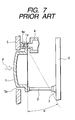
- Various operation keys and a display unit are arranged on a front panel (control panel) of an on-vehicle electric appliance such as a car air conditioner and a car audio. These operation keys serve to actuate switching elements such as push switches provided at a rear face of the front panel, and, as shown in Fig. 7a, conventional switching device has a structure wherein an
operation key 1 having its upper end pivoted is pressed from the front so that aswitching element 3 is press-driven via a driving rod 2 (see JP-A-2001-14978 (Fig. 2), for example). - In the conventional switching device shown in Fig. 7, an
axis 1a is provided at the upper end of theoperation key 1. Since theaxis 1a is pivoted on aholding plate 4a of a supporting case 4, theoperation key 1 is supported by the supporting case 4 in such a fashion that it rotates within the range of predetermined angles using theaxis 1a as a rotation axis. Thefront panel 5 has an opening 5a for placing therein theoperation key 1, and theoperation key 1 moves backward (toward right side in the drawing) in the opening 5a when an operating force indicated by an arrow F is applied to theoperation key 1 by pressing. Acircuit substrate 6 is provided upright at a region on a rear face of the front panel 4, and a pushtype switching element 3 is mounted on thecircuit substrate 6. Thedriving rod 2 is provided between a bottom end of theoperation key 1 and theswitching element 3, and thedriving rod 2 moves toward thecircuit substrate 6 when theoperation key 1 is pressed. - Accordingly, it is possible to actuate the switching
element 3 by pressing theoperation key 1 to move thedriving rod 2 by a predetermined stroke. Further, by releasing the operation force in such ON state, theoperation key 1 is pressed back via thedriving rod 2 by way of a self reset force of the switchingelement 3 returning to the OFF position, so that theoperation key 1 automatically returns to the original non-operation position. In addition, a switching device having a structure wherein thefront panel 5 rotatably supports the upper end of theoperation key 1 in place of the supporting case 4 is known. - In the case of assembly of the conventional switching device described above, it is necessary to secure in the
front panel 5 the opening 5a having a size similar to that of theoperation key 1; however, because there has been a tendency toward an increase in size of the display unit and an increase in the number of operation keys in the front panel of the on-vehicle electric appliance due to the recent multifunctionalization, it is becoming difficult to provide thefront panel 5 withmany openings 5a for theoperation keys 1. In the case of downsizing thefront panel 5, it will be difficult to secure a sufficient number ofopenings 5a for theoperation keys 1. Of course, it is possible to use small size opening 5a if the operation key is reduced in size, but such downsizing is not preferred since it remarkably deteriorates the operability. In order to deal with the multifunctionalization of electric appliance and the downsizing of front panel, there has recently been a demand for a switching device having a novel structure wherein the openings for the operation keys to be provided in the front panel are downsized. - The present invention has been accomplished in view of the facts of the conventional technology, and an object thereof is to provide a switching device with good operability, which eliminates the need for securing a large opening for an operation key in the front panel.
- As means for achieving the above object, a switching device according to the invention comprises an operation member having an operation key pressed downward for operation and disposed at a front side (or front face, respectively) of the front panel as being rotatably supported; a driving lever engaged with the operation member and rotationally driven when the operation key is pressed; and a switching element press-driven by the rotationally-driven driving lever.
- In the thus-constituted switching device, the switching element is press-driven by way of the driving lever as the operation key projected frontward from the front panel being pressed downward, thereby enabling to operate the operation key facing upward with the ease of operating a keyboard as well as to eliminate the need for providing the front panel with a large opening for the operation key.
- In the switching device, by adapting an angle formed by a first straight line connecting a point of action of an operation force to the operation member to a center of rotation of the operation member and a second straight line connecting a point of action of an operation force to the switching element to the center of rotation to be increased at the time of operation, it is possible to dispose the operation key at a bottom end of a front face of the front panel at the same time with disposing the switching element at an arbitrary height of a rear face of the front panel; thereby eliminating the risk that the operation key will deteriorate a design and operability of the front panel and making it easier to dispose at a desired position the circuit substrate on which the switching element and the like are mounted.
- For example, when the switching element is mounted on the circuit substrate which is held upright, it is possible to have other electric components which are mounted together with the switching element on an identical plane, such as a light source, faced to the front panel. Further, in this case, by setting a spacing between the driving lever and the circuit substrate to a value smaller than a radius of a rotation axis of the driving lever, even if the rotation axis tends to be disconnected from a bearing due to an excessive operation force or shock, it is possible to avoid the disconnection owing to the circuit substrate which controls positioning of the driving lever having the bearing. Therefore, improvements in assembly and a reduction in number of components are easily achieved since it is possible to attain sufficient assembly strength even by employing the simple attachment structure of snap-fitting the driving lever to the supporting member.
- Further, in the switching device where the operation key projecting from the front face of the front panel is connected to a key holder supported rotatably as being disposed at the rear side (or rear face, respectively) of the front panel in the operation member and the key holder is engaged with the driving lever, the opening required on the front panel for the operation member can be significantly small since it is possible to connect the operation key to the key holder from the front and the rear of the front panel.
- An embodiment of the invention will be described with reference to the drawings wherein:
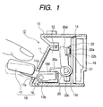
- Fig. 1 is a sectional view showing a switching unit in which a switching device according to this embodiment is incorporated;
- Fig. 2 is a broken perspective view showing the switching unit;
- Fig. 3 is a diagram illustrating an operations of the switching device;
- Fig. 4 is a sectional view showing the supporting device shown in Figs. 1 and 2;
- Fig. 5 is a diagram showing a rear face of the front panel shown in Figs. 1 and 2;
- Fig. 6 is a sectional view showing the front panel; and
- Fig. 7 shows a prior art switching unit.
-
- A
switching unit 10 shown in Figs. 1 and 2 is a part of an on-vehicle electric appliance and constituted essentially of afront panel 11, a plurality ofswitching devices 12 including a supportingcase 13, acircuit substrate 14 on which arubber sheet 22 is mounted, aconnector 15, and acover 16. Here, each of theswitching devices 12 has anoperation member 19 constituted of anoperation key 17 and akey holder lever 18 coupled to theoperation key 17, adriving lever 20 rotationally driven by thekey holder lever 18, a pair of pushtype switching elements 21 press-driven by thedriving lever 20, and the supportingcase 13 rotatably supporting thekey holder lever 18 and thedriving lever 20, and the supportingcase 13 is shared among the plurality ofswitching devices 12. The switchingelement 21 is a known one which has amovable contact portion 22b provided inside aclick rubber 22a having the shape of a dome and projecting from therubber sheet 22 and a fixedcontact portion 14a provided on thecircuit substrate 14, wherein themovable contact portion 22b and thefixed contact portion 14a face to each other as being connectable/disconnectable and themovable contact portion 22b is brought to contact with thefixed contact portion 14a when theclick rubber 22a is pressed for a predetermined stroke to be buckled. - The
front panel 11 is provided with a plurality ofopenings 11a in each of which a connectingshaft 17a of each of theoperation keys 17 is placed and a plurality ofdisplay units 11b illuminated by light from alight emitting diode 23 mounted on thecircuit substrate 14. Astiffening rib 11c is projected from the rear face of thefront panel 11 as shown in Figs. 5 and,6. Thefront panel 11 is attached to a front end of the supportingcase 13. - The
operation key 17 is disposed at a front face of thefront panel 11 with its pressedsurface 17b being faced upward and is pressed downward. The connectingshaft 17a of theoperation key 17 penetrates through the opening 11a of thefront panel 11 to be press-fitted into afitting hole 18a of thekey holder lever 18. The connectingshaft 17a press-fitted into thefitting hole 18a is fixed to thekey holder lever 18 with a fixing screw 24. Thus, theoperation key 17 and thekey holder lever 18 constituting theoperation member 19 are connected to each other strongly. Amounting plate 18b is projected from each side of thekey holder lever 18, and ahole 18c for inserting thereinto aboss 13b of theholding plate 13a projected from a front portion of the supportingcase 13 is formed on each of themounting plates 18b. Since theholding plate 13a has a flexibility in a direction of plate thickness, it is possible to achieve a state wherein thekey holder lever 18 is rotatably supported by the supportingcase 13 by thrusting thekey holder lever 18 between a pair of theholding plates 13a facing to each other, whereby snapping thebosses 13b serving as rotation axes into theholes 18c at the time of assembly. Thefront panel 11 is attached to the supportingcase 13 after thus snap-fitting thekey holder lever 18 to the front portion of the supportingcase 13, so that thestiffening rib 11c is disposed at a position controlling the flexibility of theholding plate 13a. A pair of engagement faces 18d on whichprojection pieces 20a of thedriving lever 20 are mounted is provided respectively on shoulders of thekey holder lever 18 sandwiching thefitting hole 18a. - Formed on each side of the
driving lever 20 is thehole 20b into which theboss 13c projected from a rear portion of the supportingcase 13 is inserted and abearing 20c engaging with about a half of a periphery of theboss 13c as being adjacent to thehole 20b. It is possible to achieve a state wherein the drivinglever 20 is engaged with thekey holder lever 18 at the same time with being rotatably supported by the supportingcase 13, by snapping thebosses 13c of the supportingcase 13 into theholes 20b whereby mounting theprojection pieces 20a on the engagement faces 18d of thekey holder lever 18. Thecircuit substrate 14 on which therubber sheet 22 is mounted is disposed at a position facing to a rear face of thedriving lever 20 after thus snap-fitting thedriving lever 20 to the rear portion of the supportingcase 13, and a spacing d between thedriving lever 20 and thecircuit substrate 14 is so set as to be smaller than a radius r of theboss 13c serving as the rotation axis of thedriving lever 20 as shown in Fig. 3. Thus, even when the drivinglever 20 is positioned erroneously due to a large external force, it is possible to prevent such a positioning error that causes theboss 13c to come off from thebearing 20c thanks to the control by thecircuit substrate 14. In addition, the upper end of thedriving lever 20 serves as apresser 20d which is normally in contact with the top of theclick rubber 22a. - The rear face of the
circuit substrate 14 is supported by thecover 16, and thecover 16 is attached to the supportingcase 13 as a back cover. Theclick rubber 22a of therubber sheet 22 mounted on thecircuit substrate 14 is incorporated in thepresser 20d of thedriving lever 20 with a pretension. Theconnector 15 is connected to thecircuit substrate 14, and acable 25 led from theconnector 15 is extended outward from a rear face of thecover 16. - In the case of assembly of the thus-constituted
switching unit 10, the connectingshaft 17a of theoperation key 17 inserted into the opening 11a of thefront panel 11 is pressed into thefitting hole 18a of thekey holder lever 18, and then the fixing screw 24 is clamped to form theoperation member 19 into an integrated body. Next, theboss 13b serving as the rotation axis is snapped into thehole 18c to rotatably attach theoperation member 19 to the front portion of the supportingcase 13. Then, thefront panel 11 is attached to the front end of the supportingcase 13. Theboss 13c serving as rotation axis is snapped into thehole 20b to rotatably mount thedriving lever 20 on the rear portion of the supportingcase 13 as well as to mount theprojection piece 20a of thedriving lever 20 on theengagement face 18d of thekey holder lever 18. Theconnector 15 is connected to thecircuit substrate 14 on which therubber sheet 22 is mounted so that thecircuit substrate 14 is provided upright at the rear face of thedriving lever 20, and then thecover 16 supporting thecircuit substrate 14 and theconnector 15 from their rear faces is attached to the supportingcase 13 as the back cover, whereby finishing the assembly. - Hereinafter, an operation of the
switching unit 10 will be described. In a non-operation state, theoperation member 19 maintains the posture indicated by a solid line in Fig. 1 and theoperation key 17 is positioned at the uppermost point within rotation range, since theprojection piece 20a of thedriving lever 20 presses theengagement face 18d of thekey holder lever 18 downward owing to the pretension of theclick rubber 22a. - In this state, when an operator presses the pressed
surface 17b of theoperation key 17 downward, thekey holder lever 18 is rotationally driven via the connectingshaft 17a to rotate theoperation member 19 in the anti-clock direction (in a direction of an arrow A in Fig. 3) with theboss 13b being used as the rotation axis, so that theengagement face 18d presses up theprojection piece 20a to rotate thedriving lever 20 in a direction of an arrow B, whereby thepresser 20d presses the clickrubber 22a. Then, when theoperation key 17 is pressed down to the position indicated by a broken line in Fig. 1, theclick rubber 22a is pressed by thepresser 20d by the predetermined stroke to buckle, so that themovable contact portion 22b is brought into contact with thefixed contact portion 14a thereby to switch the state of the switchingelement 21 from OFF to ON. - More specifically, in the
switching device 12 of this embodiment, an angle α formed by a first straight line L1 connecting a point of action of the operation force to theoperation member 19 to a center of rotation P of theoperation member 19 and a second straight line L2 connecting a point of action of the operation force to the switchingelement 21 to the center of rotation P is increased at the time of operation as shown in Fig. 3. In contrast, in the conventional switching device shown in Fig. 7, the angle α is reduced at the time of operation. In other words, the switchingdevice 12 of this embodiment has a structure wherein the pressedsurface 17b of the operation key 17 moves away from the switchingelement 21 at the time of operation. - Further, when the operation force to the
operation key 17 is released during the ON state, the shape of theclick rubber 22a which has been buckled returns to the original dome shape, so that themovable contact portion 22b moves away from the fixedcontact portion 14a to return the switchingelement 21 to the OFF state and that theprojection piece 20a of the drivinglever 20 is pressed back by the click rubber to press down theengagement face 18d of thekey holder lever 18, thereby rotating theoperation member 19 in the reverse direction to be returned automatically to the original non-operation position. - Thus, in the
switching device 12 of this embodiment, since the operation key 17 projected from the front face of thefront panel 11 is pressed downward to press-drive the switchingelement 21 by way of the drivinglever 20, it is possible to operate the operation key 17 facing upward with the easiness of operating a keyboard. Further, since it is possible to maintain the size of theopening 11a for theoperation member 19 required for thefront panel 11 to be as small as to allow the elevation of the connectingshaft 17a, thefront panel 11 affords a space to be easily adopted to multifunctionalization of an electric appliance, making it easy to achieve downsizing of thefront panel 11 itself. - Also, since the switching
device 12 has a structure wherein the pressedsurface 17b of the operation key 17 moves away from the switchingelement 21 at the time of operation, it is possible to dispose the switchingelement 21 at an arbitrary height of thecircuit substrate 14 provided upright behind thefront panel 11 with the operation key 17 being disposed at the bottom end of the front face of thefront panel 11. Therefore, the operation key 17 will not damage the design of thefront panel 11, and it is possible to mount other electric components such as thelight emitting diode 23 which is preferred to be disposed opposite to thefront panel 11 at desired positions of thecircuit substrate 14. - Further, since the spacing d between the driving
lever 20 and thecircuit substrate 14 is set to a value smaller than the radius r of theboss 13c which is the rotation axis of the drivinglever 20 in this embodiment, even if theboss 13c tends to be disconnected from thebearing 20c due to an excessive operation force or shock, it is possible to avoid the disconnection owing to thecircuit substrate 14 which controls positioning of the drivinglever 20 having the bearing 20c. Therefore, advantages in improving the assembly and reducing the number of components are derived since it is possible to achieve sufficient assembly strength at the same time with employing the simple attachment structure of snap-fitting the drivinglever 20 to the rear portion of the supportingcase 13. - Though the
bosses case 13 are separately inserted into thehole 18c of theoperation member 19 and thehole 20b of the drivinglever 20 to serve as rotation axes in this embodiment, it is possible to provide theoperation member 19 and the drivinglever 20 with the rotation axes and to provide the supportingcase 13 with the bearings. Also, though theswitching device 12 in which two switchingelements 21 are simultaneously actuated by oneoperation key 17 is described by way of example, it is possible to make correspondence between oneoperation key 17 and one or three ormore switching elements 21; the structure of the switching element may be selected as required. - The present invention is carried out by way of the embodiment described above to achieve the following effects.
- Since the operation key projected from the front face of the front panel is pressed downward to rotate the driving lever which press-drive the switching element by way of the driving lever in the switching device, it is possible to operate the operation key facing upward with the easiness of operating a keyboard. Further, there is no need for providing the front panel with a large opening for the operation key, and therefore the
front panel 11 affords a space to be easily adopted to multifunctionalization of an electric appliance, making it easy to achieve downsizing of thefront panel 11 itself. - Further, in the case where the spacing d between the driving lever and the circuit substrate is set to a value smaller than the radius r of the rotation axis of the driving lever, it is possible to avoid the rotation axis from being disconnected from the bearing even when the rotation axis tends to be disconnected from the bearing due to an excessive operation force or shock since positioning of the driving lever having the bearing or the rotation axis is controlled by the circuit substrate. Therefore, advantages in improving the assembly and reducing the number of components are readily derived since it is possible to achieve sufficient assembly strength even when the simple attachment structure of snap-fitting the driving lever to the supporting case is employed.
Claims (5)
- A switching device characterized by comprising: an operation member having an operation key pressed downward for operation and disposed at a front side of a front panel as being rotatably supported; a driving lever engaged with the operation member and rotationally driven when the operation key is pressed; and a switching element press-driven by the rotationally-driven driving lever.
- The switching device according to claim 1, characterized in that an angle made by a first straight line connecting a point of action of an operation force to the operation member to a center of rotation of the operation member and a second straight line connecting a point of action of an operation force to the switching element to the center of rotation is increased at the time of operation.
- The switching device according to claim 1 or 2, characterized in that the switching element is mounted on a circuit substrate held upright.
- The switching device according to claim 2 or 3, characterized in that a spacing between the driving lever and the circuit substrate is set to a value smaller than a radius of a rotation axis of the driving lever.
- The switching device according to any one of claims 1 to 4, characterized in that the operation member has a structure wherein the operation key projecting frontward from the front panel is connected to a key holder supported rotatably as being disposed on a rear side of the front panel, the key holder being engaged with the driving lever.
Applications Claiming Priority (2)
| Application Number | Priority Date | Filing Date | Title |
|---|---|---|---|
| JP2002327212 | 2002-11-11 | ||
| JP2002327212A JP4050131B2 (en) | 2002-11-11 | 2002-11-11 | Switch device |
Publications (2)
| Publication Number | Publication Date |
|---|---|
| EP1418603A1 true EP1418603A1 (en) | 2004-05-12 |
| EP1418603B1 EP1418603B1 (en) | 2006-03-29 |
Family
ID=32105527
Family Applications (1)
| Application Number | Title | Priority Date | Filing Date |
|---|---|---|---|
| EP20030025671 Expired - Lifetime EP1418603B1 (en) | 2002-11-11 | 2003-11-10 | Switching device |
Country Status (3)
| Country | Link |
|---|---|
| EP (1) | EP1418603B1 (en) |
| JP (1) | JP4050131B2 (en) |
| DE (1) | DE60304271T2 (en) |
Cited By (1)
| Publication number | Priority date | Publication date | Assignee | Title |
|---|---|---|---|---|
| CN107946117A (en) * | 2017-12-22 | 2018-04-20 | 歌尔科技有限公司 | Electronic key protective device and the electronic product with the device |
Citations (3)
| Publication number | Priority date | Publication date | Assignee | Title |
|---|---|---|---|---|
| US2757252A (en) * | 1954-07-02 | 1956-07-31 | Talon Inc | Toggle switch |
| GB828875A (en) * | 1957-09-30 | 1960-02-24 | Allied Control Co | Electric toggle switch construction |
| US4803316A (en) * | 1985-10-16 | 1989-02-07 | Fujitsu Limited | Push button switch using dome spring and switch element thereof |
-
2002
- 2002-11-11 JP JP2002327212A patent/JP4050131B2/en not_active Expired - Fee Related
-
2003
- 2003-11-10 DE DE2003604271 patent/DE60304271T2/en not_active Expired - Lifetime
- 2003-11-10 EP EP20030025671 patent/EP1418603B1/en not_active Expired - Lifetime
Patent Citations (3)
| Publication number | Priority date | Publication date | Assignee | Title |
|---|---|---|---|---|
| US2757252A (en) * | 1954-07-02 | 1956-07-31 | Talon Inc | Toggle switch |
| GB828875A (en) * | 1957-09-30 | 1960-02-24 | Allied Control Co | Electric toggle switch construction |
| US4803316A (en) * | 1985-10-16 | 1989-02-07 | Fujitsu Limited | Push button switch using dome spring and switch element thereof |
Cited By (2)
| Publication number | Priority date | Publication date | Assignee | Title |
|---|---|---|---|---|
| CN107946117A (en) * | 2017-12-22 | 2018-04-20 | 歌尔科技有限公司 | Electronic key protective device and the electronic product with the device |
| CN107946117B (en) * | 2017-12-22 | 2020-09-29 | 歌尔科技有限公司 | Electronic key protection device and electronic product with same |
Also Published As
| Publication number | Publication date |
|---|---|
| JP2004164928A (en) | 2004-06-10 |
| EP1418603B1 (en) | 2006-03-29 |
| DE60304271T2 (en) | 2006-08-31 |
| JP4050131B2 (en) | 2008-02-20 |
| DE60304271D1 (en) | 2006-05-18 |
Similar Documents
| Publication | Publication Date | Title |
|---|---|---|
| KR100509585B1 (en) | Switch structure | |
| EP1566951B1 (en) | Portable telephone and method of manufacturing the same | |
| CA3059183C (en) | Switching and operating assembly of a switch | |
| US20050040018A1 (en) | Multi-directional switch | |
| JP2000512072A (en) | Switching device having secondary switching function | |
| CN101512699A (en) | Push button switch device | |
| EP1760742B1 (en) | Switch device and steering switch apparatus equipped with the switch device | |
| EP1843367A2 (en) | Remote controller | |
| EP1418603B1 (en) | Switching device | |
| KR100361785B1 (en) | Switch device | |
| EP1020883A2 (en) | Operating device having operating button adapted to slide in housing while being pushed to effect switching operation | |
| US8090096B2 (en) | Tilting mechanism and electronic apparatus | |
| EP1693278A2 (en) | Switch on steering wheel | |
| JP4148757B2 (en) | Switch device | |
| KR200243953Y1 (en) | Safety Interlocks for Overhead Projectors | |
| US7786399B2 (en) | Apparatus comprising a button formed with a panel and flat panel display | |
| JP4299574B2 (en) | Seesaw switch | |
| US6888080B2 (en) | Switching device | |
| JP2002522887A (en) | Operating mechanism for selectively producing electrical contact | |
| JP2003257271A (en) | Lighted push-button switch device | |
| JP4064153B2 (en) | Control operation device for vehicle air conditioning | |
| JP3496325B2 (en) | Piano handle switch | |
| JP2516066Y2 (en) | Switch device | |
| JPH0864061A (en) | Switch device for manipulation | |
| JP2012175549A (en) | Push-button device of communication equipment |
Legal Events
| Date | Code | Title | Description |
|---|---|---|---|
| PUAI | Public reference made under article 153(3) epc to a published international application that has entered the european phase |
Free format text: ORIGINAL CODE: 0009012 |
|
| AK | Designated contracting states |
Kind code of ref document: A1 Designated state(s): AT BE BG CH CY CZ DE DK EE ES FI FR GB GR HU IE IT LI LU MC NL PT RO SE SI SK TR |
|
| AX | Request for extension of the european patent |
Extension state: AL LT LV MK |
|
| 17P | Request for examination filed |
Effective date: 20040521 |
|
| 17Q | First examination report despatched |
Effective date: 20040624 |
|
| AKX | Designation fees paid |
Designated state(s): DE FR GB |
|
| GRAP | Despatch of communication of intention to grant a patent |
Free format text: ORIGINAL CODE: EPIDOSNIGR1 |
|
| GRAS | Grant fee paid |
Free format text: ORIGINAL CODE: EPIDOSNIGR3 |
|
| GRAA | (expected) grant |
Free format text: ORIGINAL CODE: 0009210 |
|
| AK | Designated contracting states |
Kind code of ref document: B1 Designated state(s): DE FR GB |
|
| REG | Reference to a national code |
Ref country code: GB Ref legal event code: FG4D |
|
| RIN1 | Information on inventor provided before grant (corrected) |
Inventor name: AMANO, TOSHIAKI,C/O ALPS ELECTRIC CO., LTD. |
|
| REF | Corresponds to: |
Ref document number: 60304271 Country of ref document: DE Date of ref document: 20060518 Kind code of ref document: P |
|
| PLBE | No opposition filed within time limit |
Free format text: ORIGINAL CODE: 0009261 |
|
| STAA | Information on the status of an ep patent application or granted ep patent |
Free format text: STATUS: NO OPPOSITION FILED WITHIN TIME LIMIT |
|
| 26N | No opposition filed |
Effective date: 20070102 |
|
| EN | Fr: translation not filed | ||
| PG25 | Lapsed in a contracting state [announced via postgrant information from national office to epo] |
Ref country code: FR Free format text: LAPSE BECAUSE OF FAILURE TO SUBMIT A TRANSLATION OF THE DESCRIPTION OR TO PAY THE FEE WITHIN THE PRESCRIBED TIME-LIMIT Effective date: 20070309 |
|
| PG25 | Lapsed in a contracting state [announced via postgrant information from national office to epo] |
Ref country code: FR Free format text: LAPSE BECAUSE OF FAILURE TO SUBMIT A TRANSLATION OF THE DESCRIPTION OR TO PAY THE FEE WITHIN THE PRESCRIBED TIME-LIMIT Effective date: 20060329 |
|
| PGFP | Annual fee paid to national office [announced via postgrant information from national office to epo] |
Ref country code: GB Payment date: 20141027 Year of fee payment: 12 Ref country code: DE Payment date: 20141201 Year of fee payment: 12 |
|
| REG | Reference to a national code |
Ref country code: DE Ref legal event code: R119 Ref document number: 60304271 Country of ref document: DE |
|
| GBPC | Gb: european patent ceased through non-payment of renewal fee |
Effective date: 20151110 |
|
| PG25 | Lapsed in a contracting state [announced via postgrant information from national office to epo] |
Ref country code: DE Free format text: LAPSE BECAUSE OF NON-PAYMENT OF DUE FEES Effective date: 20160601 Ref country code: GB Free format text: LAPSE BECAUSE OF NON-PAYMENT OF DUE FEES Effective date: 20151110 |