EP1418600A1 - Méthode et dispositif de pilotage d'un appareil interrupteur. - Google Patents
Méthode et dispositif de pilotage d'un appareil interrupteur. Download PDFInfo
- Publication number
- EP1418600A1 EP1418600A1 EP03104051A EP03104051A EP1418600A1 EP 1418600 A1 EP1418600 A1 EP 1418600A1 EP 03104051 A EP03104051 A EP 03104051A EP 03104051 A EP03104051 A EP 03104051A EP 1418600 A1 EP1418600 A1 EP 1418600A1
- Authority
- EP
- European Patent Office
- Prior art keywords
- actuator
- slave
- master
- control
- master actuator
- Prior art date
- Legal status (The legal status is an assumption and is not a legal conclusion. Google has not performed a legal analysis and makes no representation as to the accuracy of the status listed.)
- Granted
Links
- 238000000034 method Methods 0.000 title claims description 16
- 230000005284 excitation Effects 0.000 claims description 9
- 230000005540 biological transmission Effects 0.000 claims description 7
- 238000005259 measurement Methods 0.000 claims description 7
- 238000012545 processing Methods 0.000 claims description 7
- 230000008054 signal transmission Effects 0.000 claims description 6
- 230000003287 optical effect Effects 0.000 claims description 5
- 230000001276 controlling effect Effects 0.000 claims description 4
- 230000001105 regulatory effect Effects 0.000 claims description 4
- 238000006073 displacement reaction Methods 0.000 description 5
- 230000009471 action Effects 0.000 description 3
- 230000004044 response Effects 0.000 description 3
- 238000005070 sampling Methods 0.000 description 3
- 238000004364 calculation method Methods 0.000 description 2
- 230000008859 change Effects 0.000 description 2
- 239000000696 magnetic material Substances 0.000 description 2
- 230000005355 Hall effect Effects 0.000 description 1
- 230000001133 acceleration Effects 0.000 description 1
- 230000000903 blocking effect Effects 0.000 description 1
- 238000010276 construction Methods 0.000 description 1
- 230000008878 coupling Effects 0.000 description 1
- 238000010168 coupling process Methods 0.000 description 1
- 238000005859 coupling reaction Methods 0.000 description 1
- 238000013461 design Methods 0.000 description 1
- 230000001627 detrimental effect Effects 0.000 description 1
- 238000010586 diagram Methods 0.000 description 1
- 230000000694 effects Effects 0.000 description 1
- 238000005516 engineering process Methods 0.000 description 1
- 239000000835 fiber Substances 0.000 description 1
- 230000004907 flux Effects 0.000 description 1
- 238000012423 maintenance Methods 0.000 description 1
- 238000004519 manufacturing process Methods 0.000 description 1
- 230000004048 modification Effects 0.000 description 1
- 238000012986 modification Methods 0.000 description 1
- 230000002028 premature Effects 0.000 description 1
- 230000011664 signaling Effects 0.000 description 1
- 239000007787 solid Substances 0.000 description 1
- 238000003860 storage Methods 0.000 description 1
- 238000003466 welding Methods 0.000 description 1
Images
Classifications
-
- H—ELECTRICITY
- H01—ELECTRIC ELEMENTS
- H01H—ELECTRIC SWITCHES; RELAYS; SELECTORS; EMERGENCY PROTECTIVE DEVICES
- H01H9/00—Details of switching devices, not covered by groups H01H1/00 - H01H7/00
- H01H9/16—Indicators for switching condition, e.g. "on" or "off"
- H01H9/167—Circuits for remote indication
Definitions
- the present invention relates to a method for controlling an actuator slave in function of a master actuator in an electrical switch device, in particular in a relay, a contactor, a contactor-circuit breaker, a switch or other.
- the invention also relates to a device for controlling and regulating movements of a slave actuator not having a mechanical connection with a master actuator, as well as a switch device comprising such a device.
- Electrical switch devices in particular of the relay, contactor or contactor-circuit breaker, have in a known manner a master master actuator linked to main contacts and consisting for example of an electromagnet comprising a fixed part and a movable part, the latter being controlled by an excitation coil in which an electric control current flows.
- the moving part moves between a position open and a closed position allowing the opening and closing of the contacts key.
- the main actuator can thus supply or cut a connected electrical load downstream of the switch device.
- the movable part of the main actuator can be manually switched between the open position and / or the closed position.
- auxiliary actuators also called auxiliary contact blocks, used to produce different basic functions such as self-maintenance, servo-control, interlocks, couplings, signaling, etc. They can be instantaneous or Timed.
- auxiliary actuators are called slaves because their displacement is always subject to the movement of the main actuator, called the master, so that faithfully reproduce the state of it.
- a slave actuator has a movable element bearing the movable auxiliary contacts. This mobile element makes it possible to open and close the auxiliary contacts depending on the position of the main contacts.
- the movable element of an auxiliary slave actuator is mechanically driven by the moving part of the master main actuator, so that its movement is controlled by that of the main master actuator.
- the master actuator must also be powerful enough to be able to to mechanically drive not only its own moving part but also the moving parts of the associated slave actuator (s).
- the establishment of a number variable of slave actuators then risks modifying the dynamics of the actuator master, thus modifying its overall performance.
- the slave actuator (s) are necessarily placed in the direct vicinity of the master actuator and are therefore not removable.
- the slave actuator (s) must have a shape adapted to the actuator master, it is frequent that a change of caliber of the master actuator in order to cover a wide range of power, also leads to a change in slave actuators associable, which generates a large multiplicity of different products and therefore manufacturing, storage, compatibility and usability issues for users, etc ...
- the document FR2384373 proposes an assembly making it possible to know the two open / closed positions of a main circuit breaker, using two limit switches which give electrical information that can be amplified and transferred. However, this information does not allow the position of an auxiliary actuator to be controlled relative to the main actuator.
- the invention aims to avoid these drawbacks by eliminating, in an electrical switch device, the mechanical link ensuring the transmission of control of the master actuator to one or more associated slave actuators.
- the method and device described in the invention advantageously allow taking account for any disturbance in the movement of the mobile part of the master actuator, such mechanical locking, welding, speed modification and / or stroke displacement (wear of the contacts for example), in order to ensure a good enslavement between the auxiliary contacts of the slave actuator (s) and the main contacts of the master actuator, so that the movement of the auxiliary contacts follows the most as faithfully as possible the movement of the main contacts.
- the invention proposes a method for controlling the slave actuator for an electrical switch device comprising a master actuator provided with a movable part linked to main contacts and at least one slave electromagnetic actuator with a movable element linked to auxiliary contacts.
- the method includes a phase of determination of the position of the mobile part of the master actuator, a phase of transmission of a signal representative of said position to a control unit of the slave actuator, and a phase of generation by the control unit of a control command of the movable element of the slave actuator according to said signal.
- the determination of the position of the movable part of the master actuator is either produced using a position sensor, or calculated in a processing unit of the switch device from a voltage and current measurement circulating in an excitation coil of the master actuator, the latter solution advantageously avoiding the use of a position sensor.
- control method can also include a phase of regulation of the position of the mobile element by the control unit during which determines the position of the movable element of the slave actuator and regulates the piloting order, as a function of said position measurement of the movable element, so as to improve the positioning of the movable element.
- the invention also provides a control device for implementing this method.
- the control device comprises means for determining the position of the mobile part of the master actuator, means for transmitting a signal representative of said position towards the control unit, and means of generation by the control unit of a control command of the mobile element of the slave actuator in function of said signal.
- the slave actuator is for example an actuator for Voice-coil type, brushless motor type, stepper motor type or motor type linear, whose response times allow to reach the desired performances.
- the invention provides an electrical switch device comprising a master actuator and one or more slave electromagnetic actuators and comprising such a control device making it possible to control the movements of the slave actuators to the movements of the master actuator, replacing the link usual mechanics existing between master actuator and slave actuator (s), such so that some slave actuators may be distant from the master actuator.
- This invention will find a first application in the control of blocks of auxiliary contacts of the same electrical switch device.
- Other applications are also offered, in particular the control of several switching devices separated slaves between them, so as to perform functions such as control inverter, star-delta starting of the engine or other.
- the slave actuators no longer having a mechanical connection with the master actuator of the switch device, they become compatible with devices of different dimensions and sizes.
- the number of auxiliary contact blocks associated with the same device no longer influences the performance and dynamics of the master actuator of the device.
- some auxiliary contact blocks can be easily deported at a considerable distance from the device without modifying the performance.
- several separate switching devices slaved to each other thanks to the invention are not necessarily placed close to each other.
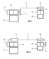
- an electrical switch device comprises a master actuator with a fixed part 15, such as a fixed cylinder head, cooperating with a movable part 10, such as a movable frame.
- the movable part 10 moves alternately between an open position and a closed position and directly or indirectly carries a or several movable main contacts, not shown in the figures.
- the party mobile is for example in the closed position
- the main mobile contacts are plated against corresponding fixed main contacts of the switching device allowing thus the passage of a main electric current, in the different poles of the device.
- the movable part is in the open position, the movable contacts are separated from the fixed contacts, so as to cut off the flow of the main electric current.
- the master actuator is an electromagnet.
- the mobile part 10 of the master actuator is in this case in magnetic material and can move under the action of an excitation coil electromagnetic 13 traversed by an electric excitation current, continuous or alternating, and possibly under the action of a return spring.
- an electric excitation current continuous or alternating
- a return spring Such a well-known device is charged supply and cut an electrical load connected downstream, such as a motor electric.
- the part mobile 10 can move under the action of a manual control and possibly a spring.
- the switch device also includes at least one slave actuator, such as than an auxiliary contact block.
- at least one slave actuator is represented. It has a fixed element 25 cooperating with a mobile element 20.
- the element mobile 20 carries one or more mobile auxiliary contacts directly or indirectly, not shown diagrammatically in the figures, and moves alternately between an open position and a closed position.
- the movable member is in the closed position, for example, the movable auxiliary contacts are pressed against fixed auxiliary contacts.
- the movable element is in the open position, the movable contacts are separated from the fixed contacts.
- auxiliary contact blocks such as normally closed contacts, normally closed contacts, contacts timers, etc ....
- the moving part of the master actuator is linked mechanically to the movable element of the slave actuator (s) of the device switch, so as to be able to mechanically control the movement of the slave actuators with that of the master actuator.
- This mechanical servo can generate the disadvantages mentioned above.
- the invention therefore aims to replace this mechanical control with an electric control.
- the slave actuator comprises an electronic control unit 22 which comprises means for generating a control order 26 sent to the mobile element 20, allowing the displacement of this mobile element 20 relative to the fixed element 25.
- the slave actuator is an actuator for Voice-coil type with a voice coil 20 traversed by a control current 26 emitted by the control unit 22.
- the voice coil 20 is associated with a fixed support 25 incorporating a permanent magnet and a core of magnetic material.
- the intensity and direction of the current control 26 circulating the voice coil 20 make it possible to fix the speed and the direction of the displacement of the coil 20 relative to the fixed support 25.
- a linear actuator of the type Voice-coil is particularly suitable for such control / command applications: long stroke, effort and acceleration, short response time, simplicity of command (regulation).
- the slave actuator could also be a brushless type motor, a step motor, a linear motor, etc ...
- the control device includes means for determining the position of the movable part 10 of the actuator master.
- These determination means provide an electrical signal 5 making it possible to know at any time and in real time the position of the mobile part 10 during all closing and opening movements of the master actuator.
- these determination means comprise a sensor 11 analog capable of measuring the position of the movable part 10 in real time and providing a signal 5 representative of this position.
- Different types of known sensors are possible, such as Hall effect sensor, magneto-resistive sensor, current sensor Foucault or others.
- the means of determination do not have a position sensor but have a unit of treatment 12 in the switch device.
- This processing unit 12 comprises by example a microcontroller or microprocessor, in particular a DSP type processor, and can be installed in an integrated circuit, for example in an ASIC component, mounted on a printed circuit inside the switch device.
- the master actuator is in this case an electromagnet and the processing unit 12 has conventional means of measurement of the voltage U at the terminals of the excitation coil 13 and for measuring the intensity of the excitation current I flowing in the coil 13.
- the processing unit 12 of the switching device is capable of calculating the inductance H of the coil at any time excitation 13 and then deduce therefrom by calculation the real-time position of the mobile part 10 of the master actuator relative to the fixed part 15, according to a method described in the application document FR 02 00952.
- a sampling frequency of the order of 20 KHz or more gives satisfactory results in the context of this invention.
- the processing unit 12 could calculate other quantities, such as the coil flux, which would also allow it to determine in real time the position of the mobile part 10 of the master actuator.
- the determination means provide a representative electrical signal 5 the position of the movable part 10 of the master actuator, either by direct measurement, or by calculation, depending on the variant chosen.
- Signal 5 is therefore either an analog signal, by example if it comes from a sensor, ie a sampled digital signal. A frequency of the order of 20 KHz or more gives satisfactory results in the part of this invention.
- this signal electric 5 is transmitted in real time to the control unit 22 of each actuator slave associated with the master actuator by transmission means.
- the transmission means include a simple electrical connection between the determination means and the control unit 22.
- other link media can be used to transmit signal 5, such as for example a fiber optic link, a wireless link using the Bluetooth or other protocol.
- transform signal routing technology 5 for example: converter electrical / optical at one end of the link then optical / electrical converter at the other end.
- An optical link avoids possible risks of disturbances signal 5 electromagnetic over long distances.
- a wireless link allows easily deport the slave actuator (s) from the master actuator.
- the signal transmission means 5 replace advantageously the usual mechanical means of connection existing between actuator master and slave actuator (s), while maintaining a satisfactory response time between the appearance of a movement made by the mobile part 10 of the master actuator and its reproduction by the movable element 20 of the slave actuator.
- signal 5 is used as input by the means of generation of the electronic control unit 22 of the slave actuator so as to generate a control order 26 for the movable element 20, which constitutes a so-called phase of generation.
- the control order 26 corresponds to the control current flowing through the voice coil 20. The regulation of the position of the movable element 20 is then produced in open loop.
- control device can include means 21 for determining the position of the movable element 20 by relative to the fixed element 25. These means consist for example of a position 21.
- the control unit 22 then comprises regulation means which use the feedback from these determination means 21 to effect regulation in a closed loop of the position of the movable element 20.
- the generation means and the regulation means are produced by program inside the electronic control unit 22, this comprising by example a DSP type processor with a sampling frequency of at least 20 kHz.
- the control unit 22 is capable of easily generating the commands corresponding to all types of auxiliary contacts desired (NO, NC, timed, ).
- any movement of the movable part 10 of the actuator master is permanently detected by the determination means 11,12 during the phase determination, then is sent via signal 5 to the control unit 22 of the actuator slave during the transmission phase.
- Unit 22 is then capable, during the phase of generation and regulation, to control the movable element 20 so as to enslave the position of the auxiliary contacts at the position of the main contacts of the device switch and therefore to faithfully reproduce this displacement with a dynamic equivalent to that which can be obtained by using a conventional mechanical connection between the movable part 10 and the movable element 20.
- the electronic control unit 22 can perform various functions additional, such as a delay function, on closing and / or opening, which gives the possibility of voluntarily reintroducing a delay between the movements of the actuator master and those of the associated slave actuator (s), depending on the applications desired.
- a delay function on closing and / or opening, which gives the possibility of voluntarily reintroducing a delay between the movements of the actuator master and those of the associated slave actuator (s), depending on the applications desired.
Landscapes
- Control Of Linear Motors (AREA)
Abstract
Description
- la figure 1 représente un schéma fonctionnel d'un dispositif de pilotage conforme àl'invention,
- la figure 2 schématise un autre exemple de dispositif de pilotage conforme à l'invention.
Claims (17)
- Méthode de pilotage d'actionneur esclave pour un appareil électrique interrupteur comprenant un actionneur maítre doté d'une partie mobile (10) liée à des contacts principaux et au moins un actionneur électromagnétique esclave doté d'un élément mobile (20) lié à des contacts auxiliaires, caractérisée en ce que la méthode comporte une phase de détermination de la position de ladite partie mobile (10) de l'actionneur maítre, une phase de transmission d'un signal (5) représentatif de ladite position vers une unité de pilotage (22) de l'actionneur esclave, et une phase de génération par l'unité de pilotage (22) d'un ordre de pilotage (26) dudit élément mobile (20) de l'actionneur esclave en fonction dudit signal (5), permettant d'asservir la position dudit élément mobile (20) de l'actionneur esclave à la position de ladite partie mobile (10) de l'actionneur maítre.
- Méthode de pilotage selon la revendication 1, caractérisée en ce que la détermination de la position de la partie mobile (10) de l'actionneur maítre est réalisée à l'aide d'un capteur de position (11 ) analogique.
- Méthode de pilotage selon la revendication 1, caractérisée en ce que la détermination de la position de la partie mobile (10) de l'actionneur maítre est calculée dans une unité de traitement (12) de l'appareil interrupteur à partir d'une mesure de la tension et du courant circulant dans une bobine d'excitation (13) de l'actionneur maítre.
- Méthode de pilotage selon l'une des revendications 1 à 3, caractérisée en ce que la transmission du signal (5) est réalisée par une liaison électrique.
- Méthode de pilotage selon l'une des revendications 1 à 3, caractérisée en ce que la transmission du signal (5) est réalisée par une liaison sans fil.
- Méthode de pilotage selon l'une des revendications 1 à 3, caractérisée en ce que la transmission du signal (5) est réalisée par une liaison optique.
- Méthode de pilotage selon l'une des revendications précédentes, caractérisée en ce qu'elle comporte en outre une phase de régulation de la position de l'élément mobile (20) par l'unité de pilotage (22) durant laquelle on détermine la position de l'élément mobile (20) de l'actionneur esclave et on régule l'ordre de pilotage (26) en fonction de ladite mesure de position de l'élément mobile (20).
- Dispositif de pilotage d'actionneur esclave pour un appareil électrique interrupteur comprenant un actionneur maítre doté d'une partie mobile (10) liée à des contacts principaux et au moins un actionneur électromagnétique esclave doté d'un élément mobile (20) lié à des contacts auxiliaires, caractérisé en ce que le dispositif comprend des moyens de détermination de la position de ladite partie mobile (10) de l'actionneur maítre, des moyens de transmission d'un signal (5) représentatif de ladite position vers une unité de pilotage (22) de l'actionneur esclave, et des moyens de génération par l'unité de pilotage (22) d'un ordre de pilotage (26) dudit élément mobile (20) de l'actionneur esclave en fonction dudit signal (5), permettant d'asservir la position dudit élément mobile (20) de l'actionneur esclave à la position de ladite partie mobile (10) de l'actionneur maítre.
- Dispositif de pilotage selon la revendication 8, caractérisé en ce que les moyens de détermination de la position de la partie mobile (10) de l'actionneur maítre comportent un capteur de position (11) analogique.
- Dispositif de pilotage selon la revendication 8, caractérisé en ce que les moyens de détermination de la position de la partie mobile (10) de l'actionneur maítre comportent une unité de traitement (12) dans l'appareil interrupteur capable de calculer ladite position à partir de la mesure de la tension et du courant circulant dans une bobine d'excitation (13) de l'actionneur maítre.
- Dispositif de pilotage selon l'une des revendications 8 à 10, caractérisé en ce que les moyens de transmission du signal (5) comportent une liaison électrique entre l'actionneur maítre et l'actionneur esclave.
- Dispositif de pilotage selon l'une des revendications 8 à 10, caractérisé en ce que les moyens de transmission du signal (5) intègrent une liaison sans fil entre l'actionneur maítre et l'actionneur esclave.
- Dispositif de pilotage selon l'une des revendications 8 à 10, caractérisé en ce que les moyens de transmission du signal (5) intègrent une liaison optique entre l'actionneur maítre et l'actionneur esclave.
- Dispositif de pilotage selon l'une des revendications 8 à 13, caractérisé en ce que l'actionneur esclave est choisi parmi une liste comprenant un actionneur de type Voice-coil, de type moteur brushless, de type moteur pas à pas, de type moteur linéaire.
- Dispositif de pilotage selon l'une des revendications 8 à 14, caractérisé en ce qu'il comporte en outre des moyens de détermination de la position de l'élément mobile (20) de l'actionneur esclave et par le fait que l'unité de pilotage (22) comporte des moyens de régulation de l'actionneur esclave en fonction de ladite position de l'élément mobile (20).
- Appareil électrique interrupteur comprenant un actionneur maítre doté d'une partie mobile (10) liée à des contacts principaux et au moins un actionneur électromagnétique esclave doté d'un élément mobile (20) lié à des contacts auxiliaires, caractérisé en ce que l'appareil interrupteur comporte un dispositif de commande selon l'une des revendications 8 à 15 permettant d'asservir les contacts auxiliaires de l'actionneur esclave aux contacts principaux de l'actionneur maítre.
- Appareil électrique interrupteur selon la revendication 16, caractérisé en ce qu'au moins un des actionneurs esclaves est distant de l'actionneur maítre.
Applications Claiming Priority (2)
| Application Number | Priority Date | Filing Date | Title |
|---|---|---|---|
| FR0214070 | 2002-11-06 | ||
| FR0214070A FR2846783B1 (fr) | 2002-11-06 | 2002-11-06 | Methode et dispositif de pilotage d'un appareil interrupteur |
Publications (2)
| Publication Number | Publication Date |
|---|---|
| EP1418600A1 true EP1418600A1 (fr) | 2004-05-12 |
| EP1418600B1 EP1418600B1 (fr) | 2014-03-12 |
Family
ID=32104552
Family Applications (1)
| Application Number | Title | Priority Date | Filing Date |
|---|---|---|---|
| EP03104051.2A Expired - Lifetime EP1418600B1 (fr) | 2002-11-06 | 2003-11-03 | Méthode et dispositif de pilotage d'un appareil interrupteur. |
Country Status (2)
| Country | Link |
|---|---|
| EP (1) | EP1418600B1 (fr) |
| FR (1) | FR2846783B1 (fr) |
Citations (5)
| Publication number | Priority date | Publication date | Assignee | Title |
|---|---|---|---|---|
| FR2384373A1 (fr) * | 1977-03-16 | 1978-10-13 | Turck Gmbh Et Co Kg Werner | Montage pour l'enregistrement instantane des positions des disjoncteurs dans une installation a haute tension telecommandee |
| EP0252808A1 (fr) * | 1986-07-04 | 1988-01-13 | Abb Control | Dispositif de commande et de contrôle d'un contacteur et procédé de contrôle correspondant |
| WO1992000599A1 (fr) * | 1990-06-26 | 1992-01-09 | Abb Strömberg Kojeet Oy | Contact auxiliaire electronique pour un contacteur |
| EP1139361A1 (fr) * | 2000-03-31 | 2001-10-04 | Alstom | Circuit électrique pour la transmission d'une information d'état, notamment d'un organe de matériel ferroviaire roulant, et système électrique incorporant un tel circuit |
| EP1179827A1 (fr) * | 2000-08-08 | 2002-02-13 | Schneider Electric Industries SA | Appareil électrique comportant un dispositif de controle, support et dispositif de surveillance pour un tel appareil, et installation électrique les comportant |
Family Cites Families (1)
| Publication number | Priority date | Publication date | Assignee | Title |
|---|---|---|---|---|
| FR2696599B1 (fr) * | 1992-10-07 | 1994-12-09 | Alsthom Gec | Contacts auxiliaires pour appareil électrique. |
-
2002
- 2002-11-06 FR FR0214070A patent/FR2846783B1/fr not_active Expired - Fee Related
-
2003
- 2003-11-03 EP EP03104051.2A patent/EP1418600B1/fr not_active Expired - Lifetime
Patent Citations (5)
| Publication number | Priority date | Publication date | Assignee | Title |
|---|---|---|---|---|
| FR2384373A1 (fr) * | 1977-03-16 | 1978-10-13 | Turck Gmbh Et Co Kg Werner | Montage pour l'enregistrement instantane des positions des disjoncteurs dans une installation a haute tension telecommandee |
| EP0252808A1 (fr) * | 1986-07-04 | 1988-01-13 | Abb Control | Dispositif de commande et de contrôle d'un contacteur et procédé de contrôle correspondant |
| WO1992000599A1 (fr) * | 1990-06-26 | 1992-01-09 | Abb Strömberg Kojeet Oy | Contact auxiliaire electronique pour un contacteur |
| EP1139361A1 (fr) * | 2000-03-31 | 2001-10-04 | Alstom | Circuit électrique pour la transmission d'une information d'état, notamment d'un organe de matériel ferroviaire roulant, et système électrique incorporant un tel circuit |
| EP1179827A1 (fr) * | 2000-08-08 | 2002-02-13 | Schneider Electric Industries SA | Appareil électrique comportant un dispositif de controle, support et dispositif de surveillance pour un tel appareil, et installation électrique les comportant |
Also Published As
| Publication number | Publication date |
|---|---|
| FR2846783A1 (fr) | 2004-05-07 |
| EP1418600B1 (fr) | 2014-03-12 |
| FR2846783B1 (fr) | 2005-01-28 |
Similar Documents
| Publication | Publication Date | Title |
|---|---|---|
| EP1466336B1 (fr) | Procede pour determiner l'usure des contacts d'un appareil interrupteur | |
| EP2037476B1 (fr) | Actionneur électromagnétique et appareil interrupteur équipé d'un tel actionneur électromagnétique | |
| EP2860869A1 (fr) | Actionneur électrique pour système de transmission de véhicule | |
| EP1485931B1 (fr) | Appareil electrique a actionneur piezoelectrique pilote | |
| EP1858035A2 (fr) | Dispositif électronique de commande pour appareil électromagnétique | |
| WO1992006483A1 (fr) | Dispositif de commutation comprenant un interrupteur auxiliaire a fonctionnement monostable couple a un interrupteur principal | |
| EP1418600B1 (fr) | Méthode et dispositif de pilotage d'un appareil interrupteur. | |
| FR2729256A1 (fr) | Methode et dispositif de controle d'un moteur synchrone monophase a aimants permanents apte a optimiser les parametres de fonctionnement meme en presence de fluctuations de la tension ou de la charge | |
| FR2896354A1 (fr) | Dispositif de commande adaptative d'un actionneur, en particulier d'embrayage ou de boite de vitesses | |
| EP1555463B1 (fr) | Dispositif de commande d'une boîte de vitesses, en particulier pour véhicule automobile | |
| FR2466034A1 (fr) | Dispositif de commande de diaphragme pour appareil de prise de vues photographiques | |
| FR2835061A1 (fr) | Procede de mesure de la position de l'armature mobile d'un electroaimant | |
| CA1154858A (fr) | Relais de delestage | |
| EP1655755A1 (fr) | Actionneur électromagnétique à bobine mobile | |
| FR2757220A1 (fr) | Perfectionnements aux procedes et aux systemes pour la commande de l'arret automatique d'un demarreur de vehicule automobile | |
| EP1139361A1 (fr) | Circuit électrique pour la transmission d'une information d'état, notamment d'un organe de matériel ferroviaire roulant, et système électrique incorporant un tel circuit | |
| FR2505577A1 (fr) | Perfectionnements aux equipements de ralentissement pour vehicules | |
| EP3018690B1 (fr) | Actionneur électromagnétique et contacteur électrique comprenant un tel actionneur | |
| BE453897A (fr) | ||
| FR2806524A1 (fr) | Commande motorisee pour disjoncteur | |
| EP1798524A1 (fr) | Capteur de position angulaire | |
| EP3121365B1 (fr) | Procédé de détection du sens de déplacement d'un écran d'occultation | |
| FR2893975A1 (fr) | Procede de commande d'un actionneur ayant un organe mobile asservi en position | |
| FR2720699A1 (fr) | Procédé de commande d'un moteur de véhicule à confort amélioré. | |
| FR2806207A1 (fr) | Electroaimant d'actionnement d'un organe mecanique notamment une soupape de moteur thermique de vehicule automobile |
Legal Events
| Date | Code | Title | Description |
|---|---|---|---|
| PUAI | Public reference made under article 153(3) epc to a published international application that has entered the european phase |
Free format text: ORIGINAL CODE: 0009012 |
|
| AK | Designated contracting states |
Kind code of ref document: A1 Designated state(s): AT BE BG CH CY CZ DE DK EE ES FI FR GB GR HU IE IT LI LU MC NL PT RO SE SI SK TR |
|
| AX | Request for extension of the european patent |
Extension state: AL LT LV MK |
|
| 17P | Request for examination filed |
Effective date: 20040611 |
|
| AKX | Designation fees paid |
Designated state(s): AT BE BG CH CY CZ DE DK EE ES FI FR GB GR HU IE IT LI LU MC NL PT RO SE SI SK TR |
|
| RAP1 | Party data changed (applicant data changed or rights of an application transferred) |
Owner name: SCHNEIDER ELECTRIC INDUSTRIES SAS |
|
| 17Q | First examination report despatched |
Effective date: 20110325 |
|
| GRAP | Despatch of communication of intention to grant a patent |
Free format text: ORIGINAL CODE: EPIDOSNIGR1 |
|
| INTG | Intention to grant announced |
Effective date: 20131127 |
|
| GRAS | Grant fee paid |
Free format text: ORIGINAL CODE: EPIDOSNIGR3 |
|
| GRAA | (expected) grant |
Free format text: ORIGINAL CODE: 0009210 |
|
| AK | Designated contracting states |
Kind code of ref document: B1 Designated state(s): AT BE BG CH CY CZ DE DK EE ES FI FR GB GR HU IE IT LI LU MC NL PT RO SE SI SK TR |
|
| REG | Reference to a national code |
Ref country code: GB Ref legal event code: FG4D Free format text: NOT ENGLISH |
|
| REG | Reference to a national code |
Ref country code: CH Ref legal event code: EP |
|
| REG | Reference to a national code |
Ref country code: AT Ref legal event code: REF Ref document number: 656778 Country of ref document: AT Kind code of ref document: T Effective date: 20140315 |
|
| REG | Reference to a national code |
Ref country code: IE Ref legal event code: FG4D Free format text: LANGUAGE OF EP DOCUMENT: FRENCH |
|
| REG | Reference to a national code |
Ref country code: DE Ref legal event code: R096 Ref document number: 60345831 Country of ref document: DE Effective date: 20140417 |
|
| REG | Reference to a national code |
Ref country code: NL Ref legal event code: VDEP Effective date: 20140312 |
|
| REG | Reference to a national code |
Ref country code: AT Ref legal event code: MK05 Ref document number: 656778 Country of ref document: AT Kind code of ref document: T Effective date: 20140312 |
|
| PG25 | Lapsed in a contracting state [announced via postgrant information from national office to epo] |
Ref country code: CY Free format text: LAPSE BECAUSE OF FAILURE TO SUBMIT A TRANSLATION OF THE DESCRIPTION OR TO PAY THE FEE WITHIN THE PRESCRIBED TIME-LIMIT Effective date: 20140312 Ref country code: FI Free format text: LAPSE BECAUSE OF FAILURE TO SUBMIT A TRANSLATION OF THE DESCRIPTION OR TO PAY THE FEE WITHIN THE PRESCRIBED TIME-LIMIT Effective date: 20140312 Ref country code: SE Free format text: LAPSE BECAUSE OF FAILURE TO SUBMIT A TRANSLATION OF THE DESCRIPTION OR TO PAY THE FEE WITHIN THE PRESCRIBED TIME-LIMIT Effective date: 20140312 |
|
| PG25 | Lapsed in a contracting state [announced via postgrant information from national office to epo] |
Ref country code: BG Free format text: LAPSE BECAUSE OF FAILURE TO SUBMIT A TRANSLATION OF THE DESCRIPTION OR TO PAY THE FEE WITHIN THE PRESCRIBED TIME-LIMIT Effective date: 20140612 Ref country code: EE Free format text: LAPSE BECAUSE OF FAILURE TO SUBMIT A TRANSLATION OF THE DESCRIPTION OR TO PAY THE FEE WITHIN THE PRESCRIBED TIME-LIMIT Effective date: 20140312 Ref country code: RO Free format text: LAPSE BECAUSE OF FAILURE TO SUBMIT A TRANSLATION OF THE DESCRIPTION OR TO PAY THE FEE WITHIN THE PRESCRIBED TIME-LIMIT Effective date: 20140312 Ref country code: NL Free format text: LAPSE BECAUSE OF FAILURE TO SUBMIT A TRANSLATION OF THE DESCRIPTION OR TO PAY THE FEE WITHIN THE PRESCRIBED TIME-LIMIT Effective date: 20140312 Ref country code: CZ Free format text: LAPSE BECAUSE OF FAILURE TO SUBMIT A TRANSLATION OF THE DESCRIPTION OR TO PAY THE FEE WITHIN THE PRESCRIBED TIME-LIMIT Effective date: 20140312 |
|
| PG25 | Lapsed in a contracting state [announced via postgrant information from national office to epo] |
Ref country code: AT Free format text: LAPSE BECAUSE OF FAILURE TO SUBMIT A TRANSLATION OF THE DESCRIPTION OR TO PAY THE FEE WITHIN THE PRESCRIBED TIME-LIMIT Effective date: 20140312 Ref country code: SK Free format text: LAPSE BECAUSE OF FAILURE TO SUBMIT A TRANSLATION OF THE DESCRIPTION OR TO PAY THE FEE WITHIN THE PRESCRIBED TIME-LIMIT Effective date: 20140312 Ref country code: ES Free format text: LAPSE BECAUSE OF FAILURE TO SUBMIT A TRANSLATION OF THE DESCRIPTION OR TO PAY THE FEE WITHIN THE PRESCRIBED TIME-LIMIT Effective date: 20140312 |
|
| REG | Reference to a national code |
Ref country code: DE Ref legal event code: R097 Ref document number: 60345831 Country of ref document: DE |
|
| PG25 | Lapsed in a contracting state [announced via postgrant information from national office to epo] |
Ref country code: PT Free format text: LAPSE BECAUSE OF FAILURE TO SUBMIT A TRANSLATION OF THE DESCRIPTION OR TO PAY THE FEE WITHIN THE PRESCRIBED TIME-LIMIT Effective date: 20140714 |
|
| PLBE | No opposition filed within time limit |
Free format text: ORIGINAL CODE: 0009261 |
|
| STAA | Information on the status of an ep patent application or granted ep patent |
Free format text: STATUS: NO OPPOSITION FILED WITHIN TIME LIMIT |
|
| PG25 | Lapsed in a contracting state [announced via postgrant information from national office to epo] |
Ref country code: DK Free format text: LAPSE BECAUSE OF FAILURE TO SUBMIT A TRANSLATION OF THE DESCRIPTION OR TO PAY THE FEE WITHIN THE PRESCRIBED TIME-LIMIT Effective date: 20140312 |
|
| 26N | No opposition filed |
Effective date: 20141215 |
|
| REG | Reference to a national code |
Ref country code: DE Ref legal event code: R097 Ref document number: 60345831 Country of ref document: DE Effective date: 20141215 |
|
| PG25 | Lapsed in a contracting state [announced via postgrant information from national office to epo] |
Ref country code: IT Free format text: LAPSE BECAUSE OF FAILURE TO SUBMIT A TRANSLATION OF THE DESCRIPTION OR TO PAY THE FEE WITHIN THE PRESCRIBED TIME-LIMIT Effective date: 20140312 |
|
| PG25 | Lapsed in a contracting state [announced via postgrant information from national office to epo] |
Ref country code: BE Free format text: LAPSE BECAUSE OF NON-PAYMENT OF DUE FEES Effective date: 20141130 Ref country code: LU Free format text: LAPSE BECAUSE OF FAILURE TO SUBMIT A TRANSLATION OF THE DESCRIPTION OR TO PAY THE FEE WITHIN THE PRESCRIBED TIME-LIMIT Effective date: 20141103 Ref country code: MC Free format text: LAPSE BECAUSE OF FAILURE TO SUBMIT A TRANSLATION OF THE DESCRIPTION OR TO PAY THE FEE WITHIN THE PRESCRIBED TIME-LIMIT Effective date: 20140312 |
|
| REG | Reference to a national code |
Ref country code: CH Ref legal event code: PL |
|
| PG25 | Lapsed in a contracting state [announced via postgrant information from national office to epo] |
Ref country code: SI Free format text: LAPSE BECAUSE OF FAILURE TO SUBMIT A TRANSLATION OF THE DESCRIPTION OR TO PAY THE FEE WITHIN THE PRESCRIBED TIME-LIMIT Effective date: 20140312 Ref country code: LI Free format text: LAPSE BECAUSE OF NON-PAYMENT OF DUE FEES Effective date: 20141130 Ref country code: CH Free format text: LAPSE BECAUSE OF NON-PAYMENT OF DUE FEES Effective date: 20141130 |
|
| REG | Reference to a national code |
Ref country code: IE Ref legal event code: MM4A |
|
| PG25 | Lapsed in a contracting state [announced via postgrant information from national office to epo] |
Ref country code: IE Free format text: LAPSE BECAUSE OF NON-PAYMENT OF DUE FEES Effective date: 20141103 |
|
| PG25 | Lapsed in a contracting state [announced via postgrant information from national office to epo] |
Ref country code: GR Free format text: LAPSE BECAUSE OF FAILURE TO SUBMIT A TRANSLATION OF THE DESCRIPTION OR TO PAY THE FEE WITHIN THE PRESCRIBED TIME-LIMIT Effective date: 20140613 |
|
| PG25 | Lapsed in a contracting state [announced via postgrant information from national office to epo] |
Ref country code: HU Free format text: LAPSE BECAUSE OF FAILURE TO SUBMIT A TRANSLATION OF THE DESCRIPTION OR TO PAY THE FEE WITHIN THE PRESCRIBED TIME-LIMIT; INVALID AB INITIO Effective date: 20031103 Ref country code: TR Free format text: LAPSE BECAUSE OF FAILURE TO SUBMIT A TRANSLATION OF THE DESCRIPTION OR TO PAY THE FEE WITHIN THE PRESCRIBED TIME-LIMIT Effective date: 20140312 |
|
| REG | Reference to a national code |
Ref country code: FR Ref legal event code: PLFP Year of fee payment: 14 |
|
| REG | Reference to a national code |
Ref country code: FR Ref legal event code: PLFP Year of fee payment: 15 |
|
| REG | Reference to a national code |
Ref country code: DE Ref legal event code: R084 Ref document number: 60345831 Country of ref document: DE |
|
| REG | Reference to a national code |
Ref country code: FR Ref legal event code: PLFP Year of fee payment: 16 |
|
| PGFP | Annual fee paid to national office [announced via postgrant information from national office to epo] |
Ref country code: GB Payment date: 20191122 Year of fee payment: 17 |
|
| GBPC | Gb: european patent ceased through non-payment of renewal fee |
Effective date: 20201103 |
|
| PG25 | Lapsed in a contracting state [announced via postgrant information from national office to epo] |
Ref country code: GB Free format text: LAPSE BECAUSE OF NON-PAYMENT OF DUE FEES Effective date: 20201103 |
|
| PGFP | Annual fee paid to national office [announced via postgrant information from national office to epo] |
Ref country code: FR Payment date: 20221122 Year of fee payment: 20 Ref country code: DE Payment date: 20221128 Year of fee payment: 20 |
|
| REG | Reference to a national code |
Ref country code: DE Ref legal event code: R071 Ref document number: 60345831 Country of ref document: DE |