EP1418479A1 - Die machining method and device by v-cad data - Google Patents
Die machining method and device by v-cad data Download PDFInfo
- Publication number
- EP1418479A1 EP1418479A1 EP02758845A EP02758845A EP1418479A1 EP 1418479 A1 EP1418479 A1 EP 1418479A1 EP 02758845 A EP02758845 A EP 02758845A EP 02758845 A EP02758845 A EP 02758845A EP 1418479 A1 EP1418479 A1 EP 1418479A1
- Authority
- EP
- European Patent Office
- Prior art keywords
- processing
- data
- mold
- cells
- boundary
- Prior art date
- Legal status (The legal status is an assumption and is not a legal conclusion. Google has not performed a legal analysis and makes no representation as to the accuracy of the status listed.)
- Granted
Links
Images



Classifications
-
- G—PHYSICS
- G05—CONTROLLING; REGULATING
- G05B—CONTROL OR REGULATING SYSTEMS IN GENERAL; FUNCTIONAL ELEMENTS OF SUCH SYSTEMS; MONITORING OR TESTING ARRANGEMENTS FOR SUCH SYSTEMS OR ELEMENTS
- G05B19/00—Program-control systems
- G05B19/02—Program-control systems electric
- G05B19/18—Numerical control [NC], i.e. automatically operating machines, in particular machine tools, e.g. in a manufacturing environment, so as to execute positioning, movement or co-ordinated operations by means of program data in numerical form
- G05B19/4097—Numerical control [NC], i.e. automatically operating machines, in particular machine tools, e.g. in a manufacturing environment, so as to execute positioning, movement or co-ordinated operations by means of program data in numerical form characterised by using design data to control NC machines, e.g. CAD/CAM
-
- G—PHYSICS
- G05—CONTROLLING; REGULATING
- G05B—CONTROL OR REGULATING SYSTEMS IN GENERAL; FUNCTIONAL ELEMENTS OF SUCH SYSTEMS; MONITORING OR TESTING ARRANGEMENTS FOR SUCH SYSTEMS OR ELEMENTS
- G05B2219/00—Program-control systems
- G05B2219/30—Nc systems
- G05B2219/35—Nc in input of data, input till input file format
- G05B2219/35097—Generation of cutter path, offset curve
-
- G—PHYSICS
- G05—CONTROLLING; REGULATING
- G05B—CONTROL OR REGULATING SYSTEMS IN GENERAL; FUNCTIONAL ELEMENTS OF SUCH SYSTEMS; MONITORING OR TESTING ARRANGEMENTS FOR SUCH SYSTEMS OR ELEMENTS
- G05B2219/00—Program-control systems
- G05B2219/30—Nc systems
- G05B2219/35—Nc in input of data, input till input file format
- G05B2219/35098—Automatic coarse, rough and finish cutting path generation
-
- G—PHYSICS
- G05—CONTROLLING; REGULATING
- G05B—CONTROL OR REGULATING SYSTEMS IN GENERAL; FUNCTIONAL ELEMENTS OF SUCH SYSTEMS; MONITORING OR TESTING ARRANGEMENTS FOR SUCH SYSTEMS OR ELEMENTS
- G05B2219/00—Program-control systems
- G05B2219/30—Nc systems
- G05B2219/35—Nc in input of data, input till input file format
- G05B2219/35145—Voxel map, 3-D grid map
-
- G—PHYSICS
- G05—CONTROLLING; REGULATING
- G05B—CONTROL OR REGULATING SYSTEMS IN GENERAL; FUNCTIONAL ELEMENTS OF SUCH SYSTEMS; MONITORING OR TESTING ARRANGEMENTS FOR SUCH SYSTEMS OR ELEMENTS
- G05B2219/00—Program-control systems
- G05B2219/30—Nc systems
- G05B2219/35—Nc in input of data, input till input file format
- G05B2219/35167—Automatic toolpath generation and tool selection
-
- G—PHYSICS
- G05—CONTROLLING; REGULATING
- G05B—CONTROL OR REGULATING SYSTEMS IN GENERAL; FUNCTIONAL ELEMENTS OF SUCH SYSTEMS; MONITORING OR TESTING ARRANGEMENTS FOR SUCH SYSTEMS OR ELEMENTS
- G05B2219/00—Program-control systems
- G05B2219/30—Nc systems
- G05B2219/45—Nc applications
- G05B2219/45204—Die, mould making
-
- Y—GENERAL TAGGING OF NEW TECHNOLOGICAL DEVELOPMENTS; GENERAL TAGGING OF CROSS-SECTIONAL TECHNOLOGIES SPANNING OVER SEVERAL SECTIONS OF THE IPC; TECHNICAL SUBJECTS COVERED BY FORMER USPC CROSS-REFERENCE ART COLLECTIONS [XRACs] AND DIGESTS
- Y02—TECHNOLOGIES OR APPLICATIONS FOR MITIGATION OR ADAPTATION AGAINST CLIMATE CHANGE
- Y02P—CLIMATE CHANGE MITIGATION TECHNOLOGIES IN THE PRODUCTION OR PROCESSING OF GOODS
- Y02P90/00—Enabling technologies with a potential contribution to greenhouse gas [GHG] emissions mitigation
- Y02P90/02—Total factory control, e.g. smart factories, flexible manufacturing systems [FMS] or integrated manufacturing systems [IMS]
Definitions
- the present invention relates to a method and an apparatus for mold processing using V-CAD data, which can store entity data combining a shape and a physical property by small memory capacity.
- the mold is manufactured in the order of design, mold processing, assembling/finishing, trying/modification and others, and an NC processing program for the mold processing and the mold processing require most of the time.
- a large part of the processing of a mold 5 is milling using an end mill 2, and light cutting using a small-diameter tool is the main in the mold processing in which many complicated shapes are processed. Therefore, a trajectory of the small-diameter tool for the processing has a small pitch corresponding to a processing width as shown in FIG. 1C, and the processing accuracy of the mold is determined by this trajectory.
- the NC processing program becomes complicated and obsolete, and the processing time also becomes long because of the small processing width.
- This method of storing entity data divides external data consisting of boundary data of an object into rectangular parallelepiped internal cells having boundary planes orthogonal to each other and boundary cells in accordance with octree (oct-tree) division, and stores various physical properties in accordance with the respective cells.
- octree oct-tree
- a shape, a structure, physical information and history of an object can be managed in an integrated fashion, data concerning a series of processes such as design, processing, assembling, test, evaluation and others can be managed with the same data, and CAD and simulation can be integrated.
- V-CAD data the entity data combining the shape and the physical property
- the present invention has been contrived in order to solve the above-described problems by using this method. That is, it is an object of the present invention to provide a method and an apparatus for mold processing using V-CAD data, which can simplify an NC processing program for mold processing and greatly reduce a mold processing time by using the V-CAD data.
- a mold processing method for using a processing tool in accordance with V-CAD data which comprises the steps of: preparing V-CAD data obtained by dividing external data (12) consisting of boundary data of an object (1) into rectangular parallelepiped cells (13) having boundary planes orthogonal to each other in accordance with octree division and separating the respective divided cells into internal cells (13a) positioned on the inner side of the object and boundary cells (13b) including a boundary face; and generating mold data and mold processing data used for manufacturing of the object, from data of a reference plane which at least partially comes into contact with the object (1) and from the V-CAD data.
- a plurality of processing tools (2) are selected in descending order of a size in accordance with the sizes of the internal cells (13a) of a processing portion, and the processing tool is moved in the plane of the mold and along the thickness direction, thereby processing the mold. Further, the processing tool (2) having the size that its motion trajectory does not protrude from the boundary plane of a target internal cell (13a) is selected. Furthermore, the processing tool (2) is selected from a drilling tool, a milling tool, a cutting tool, a polishing tool, and an electric discharge machining tool. Moreover, the cutting tool is a metal bonded grinding stone, and it is preferable to apply the electrolytic dressing.
- a mold processing apparatus using V-CAD data comprising: a storage device (4) which stores V-CAD data obtained by dividing external data (12) consisting of boundary data of an object (1) into rectangular parallelepiped cells (13) having boundary planes orthogonal to each other in accordance with octree division and separating the respective divided cells into internal cells (13a) positioned on the inner side of the object and boundary cells (13b) including a boundary face; a data generation program (6) which generates mold data and mold processing data used for manufacturing of the object, from data of a reference plane which at least partially comes into contact with the object (1) and from the V-CAD; and an NC control device (8) which selects a plurality of processing tools (2) in descending order of a size in accordance with sizes of the internal cells (13a) of a processing portion of the mold processing data and moves the processing tool in the plane of the mold and along the thickness direction, thereby processing the mold.
- the V-CAD data is stored, which is obtained by dividing the external data (12) of the object (1) into rectangular parallelepiped cells (13) having boundary planes orthogonal to each other in accordance with octree division and separating the respective divided cells into the internal cells (13a) positioned on the inner side of the object and the boundary cells (13b) including the boundary face, the external data (12) can be stored by using a small storage capacity as a hierarchy of the cells.
- the mold data and the mold processing data used to manufacture the object are generated from the data of a reference plane which is at least partially comes into contact with the object (1) and from the V-CAD data, a plurality of the processing tools (2) are selected in descending order of a size in accordance with sizes of the internal cells (13a) of the processing portion, and the processing tool is moved in the plane of the mold and along the thickness direction, thereby processing the mold. Therefore, the NC processing program for mold processing can be simplified and the mold processing time can be substantially greatly reduced by eliminating and processing the internal cells by using the relatively large processing tool (2) and then processing the boundary cells (13b) by the small processing tool.
- FIG. 2 is an overall structural view of a mold processing apparatus according to the present invention.
- the mold processing apparatus according to the present invention includes: a storage device 4 which stores V-CAD data; a data generation program 6 which generates mold data and mold processing data; and an NC control device 8 which processes a mold 5 by using the mold processing data.
- this mold processing apparatus includes: a processing tool 2 (for example, a ball end mill) which is a tool to process the mold 5; a high-speed motor 10 which rotates the processing tool 2 at a high speed; and a triaxial drive device 11 which moves the processing tool 2 in the directions X, Y and Z.
- the triaxial drive device 11 is numerically controlled by the NC control device 8.
- the processing tool 2 can be arbitrarily selected and replaced from a plurality of processing tools with different sizes by a non-illustrated automatic replacement device.
- the processing tool 2 is not restricted to a ball end mill, and it may be any of a drilling tool, a milling tool, a cutting tool, a polishing tool, an electric discharge machining tool and others.
- the cutting tool is a metal bonded grinding stone and it is preferable to apply the electrolytic dressing thereto.
- the cutting tool and the electric discharge machining tool are not restricted to rotary tools, and a non-rotary tool may be used. In this case, as to the cutting too, applying supersonic vibrations to a rectangular tool equivalent to the cell can suffice. Also, in regard to the electric discharge tool, a rectangular electrode equivalent to the cell can be used.
- the storage device 4 stores the V-CAD data.
- This V-CAD data is obtained by dividing external data 12 consisting of boundary data of an object 1 into rectangular parallelepiped cells 13 having boundary planes orthogonal to each other in accordance with octree division and separating the respective divided cells into internal cells 13a positioned on the inner side of the object and boundary cells 13b including a boundary face.
- FIG. 3 is an explanatory view of a data structure in the mold processing method according to the present invention.
- the modified octree space division is performed.
- the octree expression namely, the space division based on octree divides a rectangular solid 13 as a reference which includes a target solid (object) into eight (A) and recursively repeats the eight-part division processing until the solid is completely included in or excluded from each area as shown in (B), (C) and (D).
- the cell is a rectangular parallelepiped having boundary planes orthogonal to each other.
- the areas occupying in the space are represented by a hierarchical structure based on the cells, the division number or a resolution. As a result, the object in the entire space is represented as superimposition of the cells having the different sizes.
- the boundary and the inside physical property are converted into the following entity data 14 (V-CAD data) from the external data 12.
- the boundary data approximates exactly (for example, in case of a flat plane, it can be exactly reconfigured at three points included therein) or in a specified limit deviation tolerance (a position, a tangent line, a normal line and a curvature, and threshold values specified for the connectivity of them).
- a special case of an interpolation curve is a Marching Cube.
- subdivision is necessarily performed until expression at cut points on an edge line is possible and until the normal line or a main curvature and the continuity are satisfied.
- the surface of the second (quadratic) or lower order is exactly expressed, and a free-form surface is approximated by the surface in the cell based on the flat surface or the surface of the second order, thereby saving only a geometric inherent quantity.
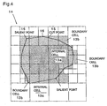
- FIG. 4 is a type drawing two-dimensionally showing the division method according to the present invention.
- the respective divided cells 13 are separated into internal cells 13a positioned on the inner side of the object and boundary cells 13b including a boundary face.
- the modified octree is used in order to express the boundary cell 13b, cells which are completely included inside are constituted by the internal cells 13a (rectangular parallelepiped) having the maximum size, and cells including boundary information from the external data 12 are constituted as the boundary cells 13b.
- Each boundary cell 13b is exactly or approximately replaced with cut points 15 (indicated by while circle in the drawing) on 12 edge lines in the three-dimensional expression or four edge lines in the two-dimensional expression.
- the boundary cell 13b is subjected to octree division until the sufficient cut points 15 can be obtained, with which boundary shape elements constituting the boundaries included in the external data 12 can be reconfigured (exactly with respect to analytic surfaces such as a flat surface or a quadric surface, and approximately with respect to boundary shape elements which can be expressed by a free-form surface or a discrete point group).
- the space is hierarchically divided into eight parts until two points on one line segment become cut points 15 on the edge line of the cell in case of one line segment, until three points become the cut points in case of a flat surface, until three points become cut points in case of a quadratic curve, until four points become cut points in case of a quadratic surface, and until necessary and sufficient points and the edge line of the cell can be found in a defined range in cases where the expression of the external data is known with respect to each of a polynomial surface and a rational expression surface.
- division is carried out until a position to be subjected to subdivision satisfies a specified resolution at a boundary (surface) part or until a rate of change of a value of an analysis result (a stress, a distortion, a pressure, a flow velocity or the like) does not exceed a specified threshold value.
- the boundary therein can be indirectly expressed as an intersecting line of the boundary expressed by the cut point 15 held by an adjacent boundary cell (which has the cut points sufficient for reconfiguration and is divided until the boundary elements completely come across), and hence subdivision is not carried out more than needs.
- the V-CAD data 14 becomes, as information concerning the shapes stored inside the cell, an index indicating a position of the cell, the division number or a resolution indicating a degree of detail in the hierarchy, a pointer indicating an adjacent cell, the number of cut points and/or coordinate values of cut points. Further, depending on use application, the V-CAD data 14 can become a normal line, a curvature or the like.
- node information or values of result are held in the form of Euler in the lowermost layer.
- a threshold value limit deviation tolerance
- the data generation program 6 generates the mold data and the mold processing data used for manufacturing of the object, from the data of the reference face which at least partially comes into contact with the object 1 and from the V-CAD data 14.
- the NC control device 8 selects a plurality of the processing tools 2 in descending order of a size in accordance with the sizes of the internal cells 13a of the processing portion of the mold processing data, and moves the processing tool in the plane of the mold and along the thickness direction, thereby processing the mold.
- FIGS. 5A and 5B are type drawings showing the mold processing method according to the present invention.
- the data generation program 6 is first used to generate the mold data and the mold processing data for manufacturing of the object 1, from the data of the reference plane which at least partially comes into contact with the object 1 (see FIG. 1) and from the V-CAD data 14.
- FIG. 5A is a side view showing the mold data in the form of V-CAD data
- FIG. 5B is a plane view of the same.
- the mold data can be separated into the internal cells 13a and the boundary cells 13b.
- a plurality of the processing tools 2 are selected in descending order of a size in accordance with the sizes of the internal cells 13a, and the processing tool 2 is moved in the plane of the mold and along the thickness direction, thereby processing the mold. Moreover, at this moment, as the processing tool 2, one having the motion trajectory which does not protrude from the boundary plane of the internal cell 13a is selected.
- the internal cell when processing the large internal cell 13a, the internal cell can be subjected to elimination processing with the simple NC processing program by using the large processing tool 2a in a short time as shown in the drawing.
- the internal cell when processing the relatively small internal cell 13a, the internal cell can be likewise subjected to elimination processing with the simple NC processing program by using the small processing tool 2b in a short time as shown in the drawing. In this manner, the internal cell 13a can be processed and eliminated with the simple program by using the relative large processing tools 2a and 2b.
- a desired mold can be finished by processing the boundary cell 13b using the small processing tool.
- the V-CAD is stored, which is obtained by dividing the external data 12 of the object 1 into rectangular parallelepiped cells 13 having boundary planes orthogonal to each other in accordance with the octree division and separating the respective divided cells into the internal cells 13a positioned on the inner side of the object and the boundary cells 13b including the boundary face, the external data 12 can be stored with a small storage capacity as a hierarchy of the cells.
- the mold data and the mold processing data used to manufacture the object are generated from the data of the reference plane which at least partially comes into contact with the object 1 and from the V-CAD, a plurality of the processing tools 2 are selected in descending order of a size in accordance with the sizes of the internal cells 13a of the processing portion, and the processing tool is moved in the plane of the mold and along the thickness direction, thereby processing the mold. Therefore, the internal cells are subjected to elimination processing by using the relatively large processing tool, and then the boundary cells 13b are processed by using the small processing tool. As a result, the NC processing program for mold processing can be simplified, and the mold processing time can be greatly reduced.
- the mold processing method and apparatus using the V-CAD data according to the present invention have the excellent advantages such as simplification of the NC processing program for mold processing and great reduction in the mold processing time by using the V-CAD data.
Landscapes
- Engineering & Computer Science (AREA)
- Human Computer Interaction (AREA)
- Manufacturing & Machinery (AREA)
- Physics & Mathematics (AREA)
- General Physics & Mathematics (AREA)
- Automation & Control Theory (AREA)
- Numerical Control (AREA)
- Mounting, Exchange, And Manufacturing Of Dies (AREA)
- Electrical Discharge Machining, Electrochemical Machining, And Combined Machining (AREA)
- Moulds For Moulding Plastics Or The Like (AREA)
Abstract
Description
Claims (6)
- A mold processing method using a processing tool, comprising the steps of:preparing V-CAD data obtained by dividing external data (12) consisting of boundary data of an object (1) into rectangular parallelepiped cells (13) having boundary planes orthogonal to each other in accordance with octree division and separating the respective divided cells into internal cells (13a) positioned on the inner side of the object and boundary cells (13b) including a boundary face; andgenerating mold data and mold processing data used for manufacturing of the object, from data of a reference plane which at least partially comes into contact with the object and from the V-CAD data.
- The mold processing method according to claim 1, wherein, in the mold processing data, a plurality of processing tools (2) are selected in descending order of a size in accordance with sizes of the internal cells (13a) of a processing portion, and the processing tool is moved in a plane of the mold and in the thickness direction, thereby processing the mold.
- The mold processing method according to claim 1, wherein, as the processing tool (2), one whose motion trajectory does not protrude from the boundary plane of the target internal cell (13a) is selected.
- The mold processing method according to claim 2 or 3, wherein the processing tool (2) is selected from a drilling tool, a milling tool, a cutting tool, a polishing tool and an electric discharge processing tool.
- The mold processing tool according to claim 4, wherein the cutting tool is a metal bonded grinding stone and electrolytic dressing is applied thereto.
- A mold processing apparatus using V-CAD data comprising:a storage device (4) which stores therein V-CAD data obtained by dividing external data (12) consisting of boundary data of an object (1) into rectangular parallelepiped cells (13) having boundary planes orthogonal to each other in accordance with octree division and separating the respective divided cells into internal cells (13a) positioned on the inner side of the object and boundary cells (13b) including a boundary face;a data generation program (6) which generates mold data and mold processing data used for manufacturing of the object, from data of a reference plane which at least partially comes into contact with the object (1) and from the V-CAD data; anda NC control device (8) which selects a plurality of processing tools (2) in descending order of a size in accordance with sizes of the internal cells (13a) of a processing portion of the mold processing data and moves the processing tool in a plane of the mold and in the thickness direction, thereby processing the mold.
Applications Claiming Priority (3)
| Application Number | Priority Date | Filing Date | Title |
|---|---|---|---|
| JP2001246949 | 2001-08-16 | ||
| JP2001246949 | 2001-08-16 | ||
| PCT/JP2002/008267 WO2003017016A1 (en) | 2001-08-16 | 2002-08-14 | Die machining method and device by v-cad data |
Publications (3)
| Publication Number | Publication Date |
|---|---|
| EP1418479A1 true EP1418479A1 (en) | 2004-05-12 |
| EP1418479A4 EP1418479A4 (en) | 2006-07-05 |
| EP1418479B1 EP1418479B1 (en) | 2007-12-26 |
Family
ID=19076386
Family Applications (1)
| Application Number | Title | Priority Date | Filing Date |
|---|---|---|---|
| EP02758845A Expired - Lifetime EP1418479B1 (en) | 2001-08-16 | 2002-08-14 | Die machining method and device by v-cad data |
Country Status (5)
| Country | Link |
|---|---|
| US (1) | US7110852B2 (en) |
| EP (1) | EP1418479B1 (en) |
| JP (1) | JP4264889B2 (en) |
| DE (1) | DE60224285T2 (en) |
| WO (1) | WO2003017016A1 (en) |
Families Citing this family (13)
| Publication number | Priority date | Publication date | Assignee | Title |
|---|---|---|---|---|
| US20050075847A1 (en) * | 2001-07-11 | 2005-04-07 | Tomonori Yamada | Method for storing entity data in which shape and physical quantity are integrated and storing program |
| US7406361B2 (en) * | 2001-08-16 | 2008-07-29 | Riken | Rapid prototyping method and apparatus using V-CAD data |
| US7174236B2 (en) * | 2001-08-16 | 2007-02-06 | Riken | Ultra-precise processing method and apparatus for inhomogeneous material |
| US7333104B2 (en) * | 2001-12-04 | 2008-02-19 | Riken | Method and program of converting three-dimensional shape data into cell internal data |
| WO2003073335A1 (en) * | 2002-02-28 | 2003-09-04 | Riken | Method and program for converting boundary data into in-cell shape |
| JP4381743B2 (en) * | 2003-07-16 | 2009-12-09 | 独立行政法人理化学研究所 | Method and program for generating volume data from boundary representation data |
| JP4608237B2 (en) * | 2004-05-20 | 2011-01-12 | 富士通株式会社 | Contour processing method |
| JP4783100B2 (en) * | 2005-09-12 | 2011-09-28 | 独立行政法人理化学研究所 | Method of converting boundary data into in-cell shape data and its conversion program |
| JP5578791B2 (en) * | 2009-02-13 | 2014-08-27 | 株式会社神戸製鋼所 | Welding line selection method |
| US11043042B2 (en) * | 2016-05-16 | 2021-06-22 | Hewlett-Packard Development Company, L.P. | Generating a shape profile for a 3D object |
| WO2020006053A1 (en) * | 2018-06-26 | 2020-01-02 | Dimitri Protopsaltis | Fabric treatment device |
| US11243510B2 (en) * | 2020-05-20 | 2022-02-08 | Autodesk, Inc. | Computer aided generative design with tool size control to facilitate 2.5-axis subtractive manufacturing processes |
| JP7697305B2 (en) * | 2021-07-29 | 2025-06-24 | 新東工業株式会社 | Hole forming device and hole forming method |
Family Cites Families (18)
| Publication number | Priority date | Publication date | Assignee | Title |
|---|---|---|---|---|
| US4534831A (en) * | 1982-09-27 | 1985-08-13 | Inoue-Japax Research Incorporated | Method of and apparatus for forming a 3D article |
| US4694404A (en) * | 1984-01-12 | 1987-09-15 | Key Bank N.A. | High-speed image generation of complex solid objects using octree encoding |
| US5197013A (en) * | 1987-07-28 | 1993-03-23 | David M. Dundorf | Method of forming a carved sign using an axially rotating carving tool |
| JPH02217134A (en) * | 1989-02-14 | 1990-08-29 | Kubota Ltd | Manufacture of die by cad-cam |
| JPH0741514B2 (en) | 1990-07-17 | 1995-05-10 | 日立精機株式会社 | Tool selection method for interactive numerical control system |
| US5517602A (en) | 1992-12-03 | 1996-05-14 | Hewlett-Packard Company | Method and apparatus for generating a topologically consistent visual representation of a three dimensional surface |
| JPH06315849A (en) | 1993-03-04 | 1994-11-15 | Nikon Corp | Formation of polishing program and forming device therewith |
| JP3367202B2 (en) * | 1994-05-19 | 2003-01-14 | 三菱電機株式会社 | Mold design support equipment |
| JP3164509B2 (en) * | 1996-06-13 | 2001-05-08 | オークマ株式会社 | Numerical control information creation device |
| US6075538A (en) * | 1996-07-25 | 2000-06-13 | Institute Of High Performance Computing | Time and space efficient data structure and method and apparatus for using the same for surface rendering |
| JP3344558B2 (en) | 1998-02-26 | 2002-11-11 | 理化学研究所 | Electric dressing grinding method and apparatus |
| JP3388203B2 (en) * | 1999-05-28 | 2003-03-17 | 株式会社半導体先端テクノロジーズ | Shape simulation method, apparatus and recording medium |
| US6214279B1 (en) * | 1999-10-02 | 2001-04-10 | Nanotek Instruments, Inc. | Apparatus and process for freeform fabrication of composite reinforcement preforms |
| US6627835B1 (en) * | 2000-02-02 | 2003-09-30 | Purdue Research Foundation | Three dimensional object fabrication techniques |
| EP1288753A4 (en) * | 2000-03-31 | 2007-08-01 | Incs Inc | DEVICE, METHOD AND PROGRAM FOR GENERATING DATA |
| US6606528B1 (en) * | 2000-06-21 | 2003-08-12 | The Boeing Company | Method for creating computer-aided design (CAD) solid models from numerically controlled (NC) machine instructions |
| US6471800B2 (en) * | 2000-11-29 | 2002-10-29 | Nanotek Instruments, Inc. | Layer-additive method and apparatus for freeform fabrication of 3-D objects |
| JP3468464B2 (en) * | 2001-02-01 | 2003-11-17 | 理化学研究所 | Volume data generation method integrating shape and physical properties |
-
2002
- 2002-08-14 DE DE60224285T patent/DE60224285T2/en not_active Expired - Lifetime
- 2002-08-14 WO PCT/JP2002/008267 patent/WO2003017016A1/en not_active Ceased
- 2002-08-14 US US10/486,659 patent/US7110852B2/en not_active Expired - Fee Related
- 2002-08-14 JP JP2003521459A patent/JP4264889B2/en not_active Expired - Fee Related
- 2002-08-14 EP EP02758845A patent/EP1418479B1/en not_active Expired - Lifetime
Also Published As
| Publication number | Publication date |
|---|---|
| EP1418479B1 (en) | 2007-12-26 |
| JPWO2003017016A1 (en) | 2004-12-09 |
| US20040267400A1 (en) | 2004-12-30 |
| DE60224285D1 (en) | 2008-02-07 |
| WO2003017016A1 (en) | 2003-02-27 |
| US7110852B2 (en) | 2006-09-19 |
| EP1418479A4 (en) | 2006-07-05 |
| DE60224285T2 (en) | 2009-01-02 |
| JP4264889B2 (en) | 2009-05-20 |
Similar Documents
| Publication | Publication Date | Title |
|---|---|---|
| US7406361B2 (en) | Rapid prototyping method and apparatus using V-CAD data | |
| US7110852B2 (en) | Die machining method and device by V-CAD data | |
| US9581992B2 (en) | Method and apparatus for a cutting process automatic generation tool of CAM | |
| KR102827365B1 (en) | Tool path generation method, tool path generation device and control device of machine tool | |
| CN106273440A (en) | Rapid shaping technique in high precision | |
| CN104084654A (en) | Six-axis linkage space shaking electrosparking method | |
| EP1431850B1 (en) | Ultra-precision machining method and device for heterogeneous material | |
| CN114842169A (en) | Shell part contour path extraction method based on STL slicing algorithm | |
| JP2002264013A (en) | Curved surface correction polishing system, NC polishing device, NC program creation method for optical component polishing, NC program creation method for polishing, 2D coordinate point group file creation method for NC program, NC program creation method, NC program automatic creation program Recording medium, optical component or mold for recording NC program for polishing | |
| Chen et al. | Variable-depth multi-pass tool path generation on mesh surfaces | |
| US6007280A (en) | Production method of pattern for casting | |
| CN108027605B (en) | Control method and control device for tool movement | |
| Si et al. | A solid-discrete-based method for extracting the cutter-workpiece engagement in five-axis flank milling | |
| CN112334847A (en) | Method for determining a rough trajectory from a given contour | |
| Kelkar et al. | Geometric algorithms for rapidly reconfigurable mold manufacturing of free-form objects | |
| Dimov et al. | Tool-path generation system for micro-electro discharge machining milling | |
| CN112000063B (en) | Die layered corner cleaning numerical control machining system and technological method thereof | |
| JP2004291097A (en) | Method, system, program and storage medium for automatically designing EDM electrodes for molding dies | |
| CN118429590A (en) | 3D printing layer cutting algorithm based on B-rep entity model | |
| Zhu et al. | Dexel-based direct slicing of multi-material assemblies | |
| CN104345686B (en) | The two-way dexel blank modeling method of two dimension and machining simulation method thereof | |
| Hatna et al. | Cartesian machining versus parametric machining: a comparative study | |
| Tseng | Machining of free-form solids using an octree volume decomposition approach | |
| CN113721551B (en) | Numerical control machining method and numerical control machining equipment | |
| Tuli | Path planning and simulation of 3D printer machine tool for development of prototypes |
Legal Events
| Date | Code | Title | Description |
|---|---|---|---|
| PUAI | Public reference made under article 153(3) epc to a published international application that has entered the european phase |
Free format text: ORIGINAL CODE: 0009012 |
|
| 17P | Request for examination filed |
Effective date: 20040216 |
|
| AK | Designated contracting states |
Kind code of ref document: A1 Designated state(s): AT BE BG CH CY CZ DE DK EE ES FI FR GB GR IE IT LI LU MC NL PT SE SK TR |
|
| AX | Request for extension of the european patent |
Extension state: AL LT LV MK RO SI |
|
| A4 | Supplementary search report drawn up and despatched |
Effective date: 20060601 |
|
| RIC1 | Information provided on ipc code assigned before grant |
Ipc: B29C 67/00 20060101ALI20060526BHEP Ipc: G05B 19/4097 20060101AFI20030305BHEP |
|
| 17Q | First examination report despatched |
Effective date: 20070209 |
|
| GRAP | Despatch of communication of intention to grant a patent |
Free format text: ORIGINAL CODE: EPIDOSNIGR1 |
|
| GRAS | Grant fee paid |
Free format text: ORIGINAL CODE: EPIDOSNIGR3 |
|
| GRAA | (expected) grant |
Free format text: ORIGINAL CODE: 0009210 |
|
| AK | Designated contracting states |
Kind code of ref document: B1 Designated state(s): DE |
|
| REF | Corresponds to: |
Ref document number: 60224285 Country of ref document: DE Date of ref document: 20080207 Kind code of ref document: P |
|
| PLBE | No opposition filed within time limit |
Free format text: ORIGINAL CODE: 0009261 |
|
| STAA | Information on the status of an ep patent application or granted ep patent |
Free format text: STATUS: NO OPPOSITION FILED WITHIN TIME LIMIT |
|
| 26N | No opposition filed |
Effective date: 20080929 |
|
| PGFP | Annual fee paid to national office [announced via postgrant information from national office to epo] |
Ref country code: DE Payment date: 20110810 Year of fee payment: 10 |
|
| PG25 | Lapsed in a contracting state [announced via postgrant information from national office to epo] |
Ref country code: DE Free format text: LAPSE BECAUSE OF NON-PAYMENT OF DUE FEES Effective date: 20130301 |
|
| REG | Reference to a national code |
Ref country code: DE Ref legal event code: R119 Ref document number: 60224285 Country of ref document: DE Effective date: 20130301 |