EP1418364A1 - Electronically controlled active suspension damper - Google Patents
Electronically controlled active suspension damper Download PDFInfo
- Publication number
- EP1418364A1 EP1418364A1 EP03445122A EP03445122A EP1418364A1 EP 1418364 A1 EP1418364 A1 EP 1418364A1 EP 03445122 A EP03445122 A EP 03445122A EP 03445122 A EP03445122 A EP 03445122A EP 1418364 A1 EP1418364 A1 EP 1418364A1
- Authority
- EP
- European Patent Office
- Prior art keywords
- fluid
- piston
- valve
- control system
- channel
- Prior art date
- Legal status (The legal status is an assumption and is not a legal conclusion. Google has not performed a legal analysis and makes no representation as to the accuracy of the status listed.)
- Withdrawn
Links
Images


Classifications
-
- F—MECHANICAL ENGINEERING; LIGHTING; HEATING; WEAPONS; BLASTING
- F16—ENGINEERING ELEMENTS AND UNITS; GENERAL MEASURES FOR PRODUCING AND MAINTAINING EFFECTIVE FUNCTIONING OF MACHINES OR INSTALLATIONS; THERMAL INSULATION IN GENERAL
- F16F—SPRINGS; SHOCK-ABSORBERS; MEANS FOR DAMPING VIBRATION
- F16F9/00—Springs, vibration-dampers, shock-absorbers, or similarly-constructed movement-dampers using a fluid or the equivalent as damping medium
- F16F9/06—Springs, vibration-dampers, shock-absorbers, or similarly-constructed movement-dampers using a fluid or the equivalent as damping medium using both gas and liquid
- F16F9/064—Units characterised by the location or shape of the expansion chamber
-
- B—PERFORMING OPERATIONS; TRANSPORTING
- B62—LAND VEHICLES FOR TRAVELLING OTHERWISE THAN ON RAILS
- B62K—CYCLES; CYCLE FRAMES; CYCLE STEERING DEVICES; RIDER-OPERATED TERMINAL CONTROLS SPECIALLY ADAPTED FOR CYCLES; CYCLE AXLE SUSPENSIONS; CYCLE SIDE-CARS, FORECARS, OR THE LIKE
- B62K25/00—Axle suspensions
- B62K25/04—Axle suspensions for mounting axles resiliently on cycle frame or fork
-
- F—MECHANICAL ENGINEERING; LIGHTING; HEATING; WEAPONS; BLASTING
- F16—ENGINEERING ELEMENTS AND UNITS; GENERAL MEASURES FOR PRODUCING AND MAINTAINING EFFECTIVE FUNCTIONING OF MACHINES OR INSTALLATIONS; THERMAL INSULATION IN GENERAL
- F16F—SPRINGS; SHOCK-ABSORBERS; MEANS FOR DAMPING VIBRATION
- F16F9/00—Springs, vibration-dampers, shock-absorbers, or similarly-constructed movement-dampers using a fluid or the equivalent as damping medium
- F16F9/32—Details
- F16F9/44—Means on or in the damper for manual or non-automatic adjustment; such means combined with temperature correction
- F16F9/46—Means on or in the damper for manual or non-automatic adjustment; such means combined with temperature correction allowing control from a distance, i.e. location of means for control input being remote from site of valves, e.g. on damper external wall
-
- B—PERFORMING OPERATIONS; TRANSPORTING
- B60—VEHICLES IN GENERAL
- B60G—VEHICLE SUSPENSION ARRANGEMENTS
- B60G2300/00—Indexing codes relating to the type of vehicle
- B60G2300/32—Track vehicles
- B60G2300/322—Snowmobiles
-
- B—PERFORMING OPERATIONS; TRANSPORTING
- B60—VEHICLES IN GENERAL
- B60G—VEHICLE SUSPENSION ARRANGEMENTS
- B60G2401/00—Indexing codes relating to the type of sensors based on the principle of their operation
- B60G2401/17—Magnetic/Electromagnetic
-
- B—PERFORMING OPERATIONS; TRANSPORTING
- B62—LAND VEHICLES FOR TRAVELLING OTHERWISE THAN ON RAILS
- B62K—CYCLES; CYCLE FRAMES; CYCLE STEERING DEVICES; RIDER-OPERATED TERMINAL CONTROLS SPECIALLY ADAPTED FOR CYCLES; CYCLE AXLE SUSPENSIONS; CYCLE SIDE-CARS, FORECARS, OR THE LIKE
- B62K25/00—Axle suspensions
- B62K25/04—Axle suspensions for mounting axles resiliently on cycle frame or fork
- B62K2025/044—Suspensions with automatic adjustment
Landscapes
- Engineering & Computer Science (AREA)
- General Engineering & Computer Science (AREA)
- Mechanical Engineering (AREA)
- Vehicle Body Suspensions (AREA)
- Fluid-Damping Devices (AREA)
Abstract
Description
- This invention relates generally to suspension dampers for vehicles such as snowmobiles or all-terrain vehicles (ATV's), and more particularly to a suspension system that provides a controlled cushioned ride.
- Vehicles such as snowmobiles and ATV's are prone to shock and vibration due to varying speed and terrain. A variety of suspension systems have been employed on snowmobiles over the years to compensate for the ruggedness of the terrain. A conventional suspension system for a snowmobile includes a number of shock absorbers, and associated springs for supporting the frame of the snowmobile. Such suspension systems usually are not automatically adjustable. Accordingly, persons of different weights or multiple passengers riding on the same vehicle could result in changes in ride or handling characteristics.
- Although conventional snowmobile suspension systems are unable to automatically adjust on a real time basis, some suspension systems do allow for manual adjustment. In these cases, riders must stop the snowmobile, turn off the engine for safety, and manually adjust the stiffness or tension provided by the shock absorbers of the snowmobile. But adjusting the conventional suspension system on snowmobiles is typically a compromise between varying conditions. For example, if the suspension system is set too hard, the shock performs poorly in trail chatter. If the system is set too soft, the shock may waste energy and bottom out on high speed impacts.
- Accordingly a system capable of continuously adjusting the vehicle's suspension to optimize performance across various speeds and terrains would be desirable.
- The present invention relates to suspension systems to increase rider comfort on a tracked vehicle. Generally, the present invention relates to a shock absorber for snowmobiles that senses both velocity and position for controlling ride characteristics. More specifically, the invention uses giant magnetoresistive (GMR) control technology to automatically adjust the vehicles suspension to optimize performance across various speeds and terrains. The shock controls the suspension in the closed position and allows for free flow of the shock's fluid in the open position. Free flow allows for no damping of the vehicles suspension, which minimizes the shock resulting from an uneven trail surface.
- The GMR senses the position and velocity of the shock rod. The microprocessor receives the information from the GMR sensor and in turn tells the control valve what to do. The actuator in the control valve receives the control signal and adjusts to regulate the fluid flow through a bypass orifice, which in turn regulates the shock damping. When the shock piston is moving rapidly due to high speed hits, large damping forces are generally desired. Conversely, when the shock piston is moving more slowly, smaller damping forces are desired.
- In one embodiment, an electronic controller and power supply, along with a giant magnetoresistive (GMR) sensor, controls the open or close condition of a bypass valve based on shock rod and piston position and velocity. Accordingly, the shock's main control piston controls the suspension action. Free flow of the shocks fluid through the control valve allows for damping of the vehicle's suspension. In one embodiment of this invention, the valve housing, remote reservoir and main body are incorporated into one casting, eliminating the need for dozens of parts and valve assembly.
- A GMR sensor in the shock reads the piston speed and position, and sends data back to a microprocessor. The circuit sends a signal to the control valve, allowing it to open and close in a time as short as milliseconds. The control valve regulates the flow of fluid through the bypass ports, which adjusts the shock damping. The end result is a smoother ride and increased track to ground contact and ski control, providing the user with increased control over changing terrain.
- The sensor system includes a magnet and sensor that work in conjunction with the bypass valve. The sensor is based on the giant magnetoresistive (GMR) effect, which detects the "flux density" of the magnetic field and converts it to a voltage signal. This voltage can indicate the speed and position of the shock piston with extreme precision. Sensor information is then relayed to an electronic control circuit, where a microprocessor uses a control algorithm to translate the voltage to command signals for the control valve.
- The above summary of the present invention is not intended to describe each disclosed embodiment or every implementation of the present invention. The figures and the detailed description that follows more particularly exemplify these embodiments.
- The invention may be more completely understood in consideration of the following detailed description of various embodiments of the invention in connection with the accompanying drawings, wherein like numerals represent like parts throughout several views, in which:
- FIG. 1 is a side elevational view of a snowmobile with some parts cut away and other parts removed, incorporating the shock absorber of the present invention;
- FIG. 2 is an isometric view of the shock absorber of the present invention;
- FIG. 3 is a reverse isometric view of the shock absorber of the present invention;
- FIG. 4 is an isometric view of an alternative embodiment of the shock absorber of the present invention;
- FIG. 5 is a reverse isometric view of an alternative embodiment of the shock absorber of the present invention;;
- FIG. 6 is a side view of the shock absorber of the present invention;
- FIG. 7 is a cross sectional view of the shock absorber taken along line A-A of FIG. 6.
- FIG. 8 is a side view of an alternative embodiment of the shock absorber of the present invention;
- FIG. 9 is a top view of an alternative embodiment of the shock absorber of the present invention;
- FIG. 10 is a cross sectional view of an alternative embodiment of the shock absorber taken along line B-B of FIG. 9.
- FIG. 11 is an end view of the shock absorber of the present invention.
- FIG. 12 is a cross sectional view of the shock absorber housing taken along line C-C of FIG. 11.
- FIG. 13 is an isometric view of the shock absorber housing of the present invention.
- FIG. 14 is an end view of the shock absorber housing of the present invention.
- FIG. 15 is a cross sectional view of the shock absorber housing taken along line D-D of FIG. 14.
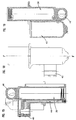
- FIG. 16 is a reverse isometric view of the shock absorber housing of the present invention.
- FIG. 17 is an isometric view of the shock absorber housing of the present invention.
- FIG. 18 is a reverse side view of the shock absorber housing of the present invention.
- FIG. 19 is a cross sectional view of the shock absorber housing taken along line F-F of FIG. 18.
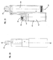
- FIG. 20 is a side view of an alternative embodiment of the shock absorber housing of the present invention.
- FIG. 21 is a cross sectional view of an alternative embodiment of the shock absorber housing taken along line G-G of FIG. 20.
- FIG. 22 is a bottom end view of an alternative embodiment of the shock absorber housing of the present invention.
- FIG. 23 is a cross sectional view of an alternative embodiment of the shock absorber housing taken along line H-H of FIG. 22.
-
- While the invention is amenable to various modifications in alternative forms, the specifics thereof have been shown by way of example in the drawings and will be described in detail. It should be understood, however, that the intention is not to limit the invention to the particular embodiments described. On the contrary, the intention is to cover all modifications, equivalents, and alternatives falling within the spirit and scope of the invention.
- The present invention is believed to be applicable to suspension systems to increase rider comfort on a tracked vehicle or ATV. The electronically controlled active suspension damper of the present invention is particularly advantageous with snowmobiles and ATV's because a variety of shock-producing surfaces are encountered while riding these vehicles. Generally, low amplitude bumps occur at high frequency while high amplitude bumps occur at a much lower frequency because the size of the bump indicates that the bumps must be spaced farther apart. Large snow drifts are examples of high amplitude, low frequency bumps. A frozen lake with a surface that has frozen unevenly due to high winds is an example of terrain with low amplitude, high frequency bumps. The electronically controlled active suspension damper of the present invention is designed to provide increased rider control in different types of terrain.
- FIG. 1 depicts a snowmobile with the electronically controlled active suspension damper of the present invention.
Snowmobile 10 includes atraction unit 11, aseat area 13, achassis 15, asteering arrangement 17, a pair of skis 12 (only one shown), afront suspension 16, and arear suspension 18.Front suspension 16 is fastened to thechassis 15. Ashock absorber 22 is disposed betweenfront suspension 16 andchassis 15 to provide front suspension action. Theshock absorber 22 provides both shock absorption and damping, as is described in detail below.Front suspension 16 may have many alternative configurations, or other linkage mechanisms. The same damping concepts discussed herein can be applied to these other configurations. -
Rear suspension 18 is pivotally attached tochassis 15 neartraction unit 11.Rear shock absorber 26 is also attached at one end tochassis 15. Whenrear suspension 18 encounters a force,rear shock absorber 26 is compressed such that thetrack 24 is allowed to move relative to thechassis 15 to dampen shock. Alternative rear suspension systems can be employed withrear shock absorber 26. An example of such a rear suspension system is found in U.S. Patent 5,664,649, incorporated herein by reference. The same damping concepts discussed herein can also be applied to these other configurations and other devices like ATV's, for example. - Referring now to FIGS. 2, 3, 6, and 11, the details of
shock absorber 22 will now be discussed. Note that whileshock absorber 22 refers to the shock absorber used with thefront suspension 16 of the snowmobile illustrated in FIG. 1, the same or similar shock absorber can be utilized on therear suspension 18.Shock absorber 22 includes arod 32 extending into amain body 34. In some embodiments, a spring 36 (shown on FIG. 1) may extend alongrod 32 and over a portion of themain body 34.Spring 36 absorbs shock and provides rebound whilerod 32 extends intomain body 34 and provides damping as explained below. -
Main body 34 enclosesfluid reservoir 38.Remote reservoir 40 may be contained in the same general casting asmain body 34 but it is located outsidefluid reservoir 38.Remote reservoir 40 containsfluid chamber 42, andchannel 43, shown in FIG. 12.Fluid chamber 42 andremote reservoir 40 are interconnected bychannel 43 that enables fluid to flow betweenfluid chamber 42 andremote reservoir 40. Alternatively, fluid may move from thefluid reservoir 38 to thefluid chamber 42 through hoses connected to fittings in the housing. - The end of the
main body 34 opposite therod 32 contains ahousing end mount 46 for mounting the end of theshock absorber 22 either to thesnowmobile chassis 15 or thefront suspension 16. Arod end mount 48 is provided on the opposite side of theshock absorber 22. In FIG. 1, therod end mount 48 is mounted to the chassis while thehousing end mount 46 is secured to thefront suspension 16. -
Spring 36 may generally be held onrod 32 andmain body 34 withspring stop 50 secured torod 32 near the end ofrod end mount 48 andpreload ring 52 at the opposite end ofspring 36. In alternative embodiments,preload ring 52 is threadably engaged onmain body 34. Therefore, by turningpreload ring 52, the preload inspring 36 may be adjusted. - A
valve housing 54 is also provided onshock absorber 22.Valve housing 54 may be contained in the same general casting asmain body 34.Valve housing 54 holds thecontrol valve 56. Thecontrol valve 56 preferably comprises a solenoid capable of actuating from the open to closed position. - Microprocessor/GMR
sensor controller unit 57 is located on the side offluid reservoir 38. Microprocessor/GMRsensor controller unit 57 contains a GMR sensor, which is capable of sensing the velocity and position of therod 32. The GMR sensor sends a signal to a microprocessor, which processes the information from the GMR sensor and actuates thecontrol valve 56. The microprocessor may also be located in thesensor controller unit 57.Power wire 59 provides electric current to the components in the microprocessor/GMRsensor controller unit 57. - Referring to FIG's. 6 and 7,
fluid reservoir 38 includes an opening at one end through whichrod 32 is inserted. Areservoir cap 63 may extend around therod 32 and be held tightly within the open end of themain body 34 to create anenclosed fluid reservoir 38. Areservoir seal 65 is also included on the outside ofreservoir cap 63.Reservoir cap 63, valves, androd seal 67 reduce the chances of hydraulic fluid escaping fromfluid reservoir 38. O-rings may generally be employed at appropriate locations to ensure adequate sealing. In alternative embodiments,reservoir cap 63 will abut a bottom outbumper 69 held onrod 32 adjacent thespring stop 50 whenrod 32 extends all the way intohydraulic reservoir 38. -
Piston assembly 64 is located onrod 32 oppositerod end mount 48.Piston assembly 64 includes compression ports that allow fluid to pass from one side ofpiston assembly 64, throughpiston assembly 64, to the other side ofpiston assembly 64 asrod 32 moves towardend mount 46.Piston assembly 64 also includes rebound ports that allow fluid to pass throughpiston assembly 64 asrod 32 moves away fromend mount 46. The compression ports and rebound ports generally have a very small diameter, which preventpiston assembly 64 from moving rapidly insidefluid reservoir 38, thereby resulting in a relatively stiff suspension. For this reason,bypass channel 44 is provided, which enables fluid to quickly move from one side ofpiston assembly 64 to the other side ofpiston assembly 64 whencontrol valve 56 is in the open position. - A GMR sensor is provided to detect both the displacement and velocity of the
piston assembly 64 relative to themain body 34. The sensor and control arrangement preferably employed in the present invention includes amagnet 66 secured on the end of thepiston assembly 64, as shown in FIG. 7. The sensor may be secured in thesensor controller unit 57. The sensor is preferably connected to a circuit board comprised of a microprocessor chip that includes the microprocessor logic to manipulate thecontrol valve 56 based on the signal from the sensor. As therod 32 moves in response to changing terrain, themagnet 66 moves past the GMR sensor located in thecontrol unit 57. The GMR sensor detects the velocity and position of themagnet 66, which corresponds to the velocity and position of therod 32. The microprocessor interprets the information from the sensor, which manipulates thecontrol valve 56. - When the
control valve 56 is in an open position, fluid is allowed to freely move throughchannel 44 and between thefluid reservoir 38 and theremote reservoir 40. Alternatively, when thecontrol valve 56 is in a closed position, the fluid cannot freely move between thefluid reservoir 38 and theremote reservoir 40. The suspension will be much stiffer because the fluid must move through the relatively small compression or rebound ports onpiston assembly 64, rather thanchannel 44. - Figures 13-19 show various views of the body of
shock absorber 22. In figure 15,channel 44 is shown.Channel 44 extends from an opening near housing end mount 46 throughvalve mount 45, along the wall offluid reservoir 38, to another opening nearreservoir cap 60.Channel 44 enables fluid to quickly pass from one side ofpiston assembly 64 to the other side ofpiston assembly 64 whenvalve 56 is in the open position.Valve mount 45 is disposed inchannel 44 so thatcontrol valve 56 is capable of obstructing the fluid movement throughchannel 44 when thecontrol valve 56 is in the closed position. - When the fluid movement through
channel 44 is obstructed, the fluid may move through the compression and rebound valves, thereby providing some shock absorption. The diameter of the compression and rebound valves is generally much smaller than the diameter of thechannel 44. Accordingly, theshock absorber 22 is much stiffer when thecontrol valve 56 is in the closed position. When thecontrol valve 56 is in the open position, fluid is permitted to move through the compression valves in addition to thechannel 44. This provides for much less damping than when thecontrol valve 56 is in the closed position. - Referring now to FIGS. 4, 5, 8, 9 and 10 the details of
alternative shock absorber 23 will now be discussed. Note that whileshock absorber 23 refers to the shock absorber used with the rear suspension of the snowmobile illustrated in FIG. 1, the same or similar shock absorber can be utilized on either the front or rear suspension of snowmobiles or ATV's. -
Shock absorber 23 is similar toshock absorber 22 in function and purpose. However,shock absorber 23 varies fromshock absorber 22 with respect to the placement of theremote reservoir 40 relative to thevalve housing 54. For example, in FIG. 4, thevalve housing 54, and thecontrol valve 56 are located in the same axis as theremote reservoir 40. Alternatively, FIGS 1 and 2 show that thevalve housing 54 and thecontrol valve 56 are each located alongside thereservoir 40. -
Shock absorber 23 includes arod 32 extending into amain body 34. A spring may extend alongrod 32 and over a portion of themain body 34.Spring 36 absorbs shock and provides rebound whilerod 32 extends intomain body 34 and provides damping as explained above. -
Main body 34 enclosesfluid reservoir 38.Remote reservoir 40 may be contained in the same general casting asmain body 34 but it is located outsidefluid reservoir 38.Remote reservoir 40 containsfluid chamber 42, shown in FIGs. 10 and 21.Fluid chamber 42 andremote reservoir 40 are interconnected bychannel 44, shown in FIG. 10. Alternatively, fluid may move from thefluid reservoir 38 to thefluid chamber 42 through hoses connected to fittings in the housing. - The end of the
main body 34 opposite therod 32 contains ahousing end mount 46 for mounting the end of theshock absorber 23 either to thesnowmobile chassis 15 or thesuspension rod end mount 48 is provided on the opposite side of theshock absorber 23. - A
valve housing 54 is also provided onshock absorber 23.Valve housing 54 can be axially aligned withremote reservoir 40 and may be contained in the same general casting asmain body 34.Valve housing 54 holds thecontrol valve 56. Thecontrol valve 56 preferably comprises a solenoid capable of actuating from the open to closed position. - Microprocessor/GMR
sensor controller unit 57 is located on the side ofshock absorber 23, generally betweenmain body 34 andremote reservoir 40. Microprocessor/GMR sensor controller unit contains the GMR sensor, which is capable of sensing the velocity and position ofmagnet 66 that is fastened to the end ofrod 32. The GMR sensor sends a signal to the microprocessor, which processes the information from the GMR sensor and actuates thecontrol valve 56.Power wire 59 provides electric current to the components in the microprocessor/GMRsensor controller unit 57. -
Fluid reservoir 38 includes an opening at one end through whichrod 32 is inserted. Areservoir cap 63 may extend around therod 32 and be held tightly within the open end of themain body 34 to create anenclosed fluid reservoir 38. O-rings may generally be employed at appropriate locations to ensure adequate sealing. - A GMR sensor is provided to detect both the displacement and velocity of
rod 32 and thepiston assembly 64 relative to themain body 34. The sensor and control arrangement preferably employed in the present invention includes amagnet 66 secured on the end of thepiston assembly 64, as shown in FIG. 10. A sensor may be secured in thesensor controller unit 57. The sensor is preferably connected to circuit board comprised of a microprocessor chip that includes the microprocessor logic to manipulate thecontrol valve 56 based on the signal from the sensor. As therod 32 moves in response to changing terrain, themagnet 66 moves past the GMR sensor located in thecontrol unit 57. The GMR sensor detects the velocity and position of themagnet 66, which corresponds to the velocity and position of therod 32. The microprocessor interprets the information from the sensor, which manipulates thecontrol valve 56. - Figures 21-23 show various views of the body of
shock absorber 23. In figure 21,valve mount 45 is shown.Valve mount 45 is disposed inchannel 44 so thatcontrol valve 56 is capable of obstructing the fluid movement throughchannel 44 when thecontrol valve 56 is in the closed position. - As shown in FIG's. 7 and 10,
piston assembly 62 contains compression and reboundvalves 60. When the fluid movement throughchannel 44 is obstructed, the fluid may move through the compression and rebound valves, thereby providing some shock absorption. The diameter of the compression and rebound valves is generally much smaller than the diameter of thechannel 44. Accordingly, theshock absorber 23 is much stiffer when thecontrol valve 56 is in the closed position. When thecontrol valve 56 is in the open position, fluid is permitted to move through the compression valves in addition to thechannel 44. This provides for much less damping than when thecontrol valve 56 is in the closed position.
Claims (26)
- A suspension control system for use with a snowmobile, ATV or motorcycle, said suspension control system comprising:a main body defining a fluid reservoir and containing a fluid;a piston disposed within the fluid reservoir, the piston being configured for movement under the force of a shock acting on the piston, the piston having first and second sides and being movable between a first piston position and a second piston position;a remote reservoir defining a fluid chamber, wherein the fluid chamber is coupled to the fluid reservoir, the fluid chamber having a channel with an outlet port, a first inlet port and a second inlet port extending through a wall of the fluid chamber and in fluid communication with the main body fluid reservoir so that fluid may flow from the fluid reservoir to the fluid chamber;a control valve operable to control the flow of the fluid from the main body fluid reservoir to the remote reservoir fluid chamber, the valve being movable from an open position, where fluid movement from the fluid reservoir through the channel to the fluid chamber is permitted, to a closed position wherein the flow of fluid through the channel is blocked, and;a GMR sensor operable to sense at least one of the displacement of the piston and the velocity of the piston and send a signal to a microprocessor for controlling the position of the control valve.
- The suspension control system of claim 1, wherein the control valve is located in the same axis as the remote reservoir.
- The suspension control system of claim 1, wherein the control valve is located alongside the remote reservoir.
- The suspension control system of claim 1, wherein the control valve is movable from an open position to a closed position in response to at least one of the extent of displacement of the piston and the velocity of displacement of the piston.
- The suspension control system of claim 1, wherein the, control valve is at least partially disposed within the channel.
- The suspension control system of claim 1, wherein the control valve comprises 2-way valve designed to function as a bi-directional blocking valve.
- The suspension control system of claim 6, wherein the control valve is biased toward the closed position.
- The suspension control system of claim 6, wherein the control valve is biased toward the open position.
- The suspension control system of claim 1, further comprising a valve housing, wherein the valve housing, remote reservoir, and main body are formed as a unitary casting.
- The suspension control system of claim 1, wherein the GMR sensor is in communication with the microprocessor and control valve.
- The suspension control system of claim 10, further comprising a power source.
- The suspension control system of claim 1, further comprising a rod having an enclosed portion located within the main body and an exposed portion located outside the main body.
- The suspension control system of claim 12, further comprising a spring disposed about the exposed portion of the rod.
- The suspension control system of claim 10, further comprising a circuit board, wherein the circuit board is electronically connected to the GMR sensor, wherein the circuit board controls the control valve's open and closed position.
- The suspension control system of claim 1, wherein the fluid comprises hydraulic fluid.
- A method of dampening a shock absorber, comprising:moving a piston through a fluid in a fluid reservoir of a dampener, the piston moving from a first position to a second position,moving a portion of the fluid into a fluid chamber through a channel, the channel being coupled to the fluid reservoir and a first chamber, the channel having an inlet port coupled to the fluid reservoir and an outlet port coupled to the first chamber,using a GMR sensor to detect the movement of the piston to the second position as the fluid moves through the channel;using a control valve to restrict the flow of fluid through the inlet port to the outlet port in response to at least one of a piston displacement or velocity of piston displacement.
- The method of claim 16, wherein the control valve is controlled by a microprocessor that receives a signal from the GMR sensor.
- A dampener for a shock absorber, comprising;a main body defining a fluid reservoir containing fluid;a piston disposed within the fluid reservoir for movement under the force of a shock acting on the piston,a remote reservoir defining a first chamber;a channel coupled to the fluid reservoir and the first chamber, the channel permitting fluid to flow from the fluid reservoir through the channel to the first chamber;a valve housing containing a control valve to control the movement of fluid through the bypass channel, the valve housing, remote reservoir and main body being formed as a unitary casting.a bypass channel connecting the top of the first chamber with the bottom of the first chamber on opposite sides of the piston, wherein the bypass channel is capable of being opened and closed by the control valve;a microprocessor in communication with a GMR sensor to control the position of the control valve.
- The dampener of claim 18, further comprising a power source to provide power to the control valve.
- The dampener of claim 18 wherein the valve is movable from an open position to a closed position in response to at least one of the extent of displacement of the piston and the velocity of displacement of the piston.
- The dampener of claim 20, wherein the valve is a solenoid-operated, bi-directional blocking valve biased in the open position.
- The dampener of claim 20, wherein the valve is a solenoid-operated, bi-directional blocking valve biased in the closed position.
- A snowmobile comprising the suspension control system of claim 1.
- An ATV comprising the suspension control system of claim 1.
- A motorcycle comprising the suspension control system of claim 1.
- A motorscooter comprising the suspension control system of claim 1.
Applications Claiming Priority (2)
| Application Number | Priority Date | Filing Date | Title |
|---|---|---|---|
| US10/290,946 US20040090020A1 (en) | 2002-11-08 | 2002-11-08 | Electronically controlled active suspension damper |
| US290946 | 2002-11-08 |
Publications (1)
| Publication Number | Publication Date |
|---|---|
| EP1418364A1 true EP1418364A1 (en) | 2004-05-12 |
Family
ID=29780398
Family Applications (1)
| Application Number | Title | Priority Date | Filing Date |
|---|---|---|---|
| EP03445122A Withdrawn EP1418364A1 (en) | 2002-11-08 | 2003-10-27 | Electronically controlled active suspension damper |
Country Status (4)
| Country | Link |
|---|---|
| US (1) | US20040090020A1 (en) |
| EP (1) | EP1418364A1 (en) |
| CA (1) | CA2448158A1 (en) |
| NO (1) | NO20034966L (en) |
Cited By (6)
| Publication number | Priority date | Publication date | Assignee | Title |
|---|---|---|---|---|
| EP1816063A3 (en) * | 2006-02-01 | 2009-11-18 | Honda Motor Co., Ltd | Rear-wheel suspension for two-wheeled vehicle |
| GB2480628A (en) * | 2010-05-25 | 2011-11-30 | Horstman Defence Systems Ltd | A suspension unit for use on a tracked vehicle including a load sensor |
| WO2013185132A1 (en) * | 2012-06-08 | 2013-12-12 | Msi Defense Solutions, Llc | An electronically adjustable damper and system |
| US8641067B2 (en) | 2010-05-25 | 2014-02-04 | Horstman Defence Systems Limited | Suspension unit |
| US8757303B2 (en) | 2010-05-25 | 2014-06-24 | Horstman Defence Systems Limited | Suspension unit |
| US9004504B2 (en) | 2010-05-25 | 2015-04-14 | Horstman Defence Systems Limited | Vehicle |
Families Citing this family (33)
| Publication number | Priority date | Publication date | Assignee | Title |
|---|---|---|---|---|
| US6892865B2 (en) * | 2003-08-01 | 2005-05-17 | Arvin Technologies, Inc. | Monotube shock absorber remote reservoir fluid connection |
| US9169889B1 (en) | 2006-02-13 | 2015-10-27 | Fox Factory, Inc. | Fluid pressure operated device with adjustable positioning of mounting elements relative to externally mounted structures |
| SE531628C2 (en) * | 2006-03-20 | 2009-06-09 | Oehlins Racing Ab | Attenuator device and manufacture of such attenuator device |
| US7621382B2 (en) * | 2006-06-28 | 2009-11-24 | Nissan Technical Center North America, Inc. | Shock absorber |
| US7946163B2 (en) | 2007-04-02 | 2011-05-24 | Penske Racing Shocks | Methods and apparatus for developing a vehicle suspension |
| EP2036746B1 (en) * | 2007-09-17 | 2014-07-23 | S & T Daewoo Co., Ltd. | Sensor module comprising acceleration sensor and relative displacement sensor, damper and electronically controllable suspension system comprising the same, and method of controlling vehicle movement using the same |
| US8616351B2 (en) | 2009-10-06 | 2013-12-31 | Tenneco Automotive Operating Company Inc. | Damper with digital valve |
| US8727047B2 (en) * | 2012-01-26 | 2014-05-20 | Claas Industrietechnik Gmbh | Configuration of a two-track tractor |
| ES2699245T3 (en) | 2012-11-07 | 2019-02-08 | Polaris Inc | Vehicle with suspension with continuous damping control |
| US9205717B2 (en) | 2012-11-07 | 2015-12-08 | Polaris Industries Inc. | Vehicle having suspension with continuous damping control |
| US9884533B2 (en) | 2013-02-28 | 2018-02-06 | Tenneco Automotive Operating Company Inc. | Autonomous control damper |
| US9217483B2 (en) | 2013-02-28 | 2015-12-22 | Tenneco Automotive Operating Company Inc. | Valve switching controls for adjustable damper |
| WO2014134500A1 (en) | 2013-02-28 | 2014-09-04 | Tenneco Automotive Operating Company Inc. | Damper with integrated electronics |
| WO2014144110A1 (en) | 2013-03-15 | 2014-09-18 | Tenneco Automotive Operating Company Inc. | Rod guide assembly with multi-piece valve assembly |
| US9163691B2 (en) | 2013-03-15 | 2015-10-20 | Tenneco Automotive Operating Company Inc. | Rod guide arrangement for electronically controlled valve applications |
| US9879748B2 (en) | 2013-03-15 | 2018-01-30 | Tenneco Automotive Operating Company Inc. | Two position valve with face seal and pressure relief port |
| US9879746B2 (en) | 2013-03-15 | 2018-01-30 | Tenneco Automotive Operating Company Inc. | Rod guide system and method with multiple solenoid valve cartridges and multiple pressure regulated valve assemblies |
| US9428028B2 (en) | 2013-05-31 | 2016-08-30 | Skinz Protective Gear | Remotely adjustable degrees of freedom for suspension coupling |
| WO2014194253A1 (en) | 2013-05-31 | 2014-12-04 | Skinz Protective Gear | Remotely adjustable suspension coupling |
| US9428242B2 (en) | 2014-02-24 | 2016-08-30 | Harley-Davidson Motor Company Group, LLC | Variable ride height systems and methods |
| EP3212484A2 (en) | 2014-10-31 | 2017-09-06 | Polaris Industries Inc. | System and method for controlling a vehicle |
| CN104626911B (en) * | 2015-02-02 | 2017-01-18 | 江苏大学 | Liquid electric coupling type vehicle suspension impedance control device |
| CA2985632A1 (en) | 2015-05-15 | 2016-11-24 | Polaris Industries Inc. | Utility vehicle |
| CA3043481C (en) | 2016-11-18 | 2022-07-26 | Polaris Industries Inc. | Vehicle having adjustable suspension |
| US10588233B2 (en) | 2017-06-06 | 2020-03-10 | Tenneco Automotive Operating Company Inc. | Damper with printed circuit board carrier |
| US10479160B2 (en) | 2017-06-06 | 2019-11-19 | Tenneco Automotive Operating Company Inc. | Damper with printed circuit board carrier |
| US10406884B2 (en) | 2017-06-09 | 2019-09-10 | Polaris Industries Inc. | Adjustable vehicle suspension system |
| US10946736B2 (en) | 2018-06-05 | 2021-03-16 | Polaris Industries Inc. | All-terrain vehicle |
| CN109050769A (en) * | 2018-07-28 | 2018-12-21 | 重庆隆鑫机车有限公司 | Motorcycle bottom fork assembly and its motorcycle |
| US10987987B2 (en) | 2018-11-21 | 2021-04-27 | Polaris Industries Inc. | Vehicle having adjustable compression and rebound damping |
| CN115666975A (en) * | 2020-05-20 | 2023-01-31 | 北极星工业有限公司 | System and method for adjustable suspension for off-road recreational vehicles |
| CA3182725A1 (en) | 2020-07-17 | 2022-01-20 | Polaris Industries Inc. | Adjustable suspensions and vehicle operation for off-road recreational vehicles |
| CN111907629B (en) * | 2020-08-14 | 2021-11-16 | 芜湖富仕德体育用品股份有限公司 | Large beach kart suitable for complicated topography has protect function of turning on one's side |
Citations (6)
| Publication number | Priority date | Publication date | Assignee | Title |
|---|---|---|---|---|
| US4153237A (en) * | 1976-11-01 | 1979-05-08 | Supalla Steven A | Hydrapneumatic suspension unit and valving structure |
| DE3420666A1 (en) * | 1984-06-02 | 1985-12-05 | Mannesmann Rexroth GmbH, 8770 Lohr | Level control device for vehicles with at least one hydraulic vibration damper |
| DE4244204A1 (en) * | 1992-12-24 | 1994-06-30 | Bosch Gmbh Robert | Displacement measurement system for shock absorber cushioning stroke |
| DE19547910C1 (en) * | 1995-12-21 | 1997-01-16 | Bilstein August Gmbh Co Kg | Device for influencing characteristics of a vibration damper |
| US6244398B1 (en) * | 1997-05-15 | 2001-06-12 | K2 Bike Inc. | Shock absorber with variable bypass damping |
| US20010025752A1 (en) * | 1997-07-08 | 2001-10-04 | Crawley Edward F. | Damper and valve |
Family Cites Families (16)
| Publication number | Priority date | Publication date | Assignee | Title |
|---|---|---|---|---|
| DE3414258A1 (en) * | 1984-04-14 | 1985-10-24 | Robert Bosch Gmbh, 7000 Stuttgart | DEVICE FOR CONTROLLING THE SUSPENSION OF A VEHICLE I |
| DE3430045C2 (en) * | 1984-08-16 | 1986-07-17 | Boge Gmbh, 5208 Eitorf | Device for determining the path of a piston |
| US4746106A (en) * | 1986-08-15 | 1988-05-24 | Nhk Spring Co., Ltd. | Car suspension system |
| JPS63301115A (en) * | 1987-05-29 | 1988-12-08 | Nissan Motor Co Ltd | Hydraulic suspension |
| ES2032189T3 (en) * | 1990-11-17 | 1997-10-01 | Krupp Bilstein Gmbh | SENSOR TO MEASURE THE RELATIVE SPEED AND / OR THE POSITION BETWEEN A DAMPER CYLINDER AND A DAMPING PISTON WHICH MOVES WITHIN IT. |
| US5533586A (en) * | 1994-02-01 | 1996-07-09 | Arctco, Inc. | Adjustable suspension system |
| JPH04372410A (en) * | 1991-06-20 | 1992-12-25 | Tokico Ltd | Suspension device |
| US5396973A (en) * | 1991-11-15 | 1995-03-14 | Lord Corporation | Variable shock absorber with integrated controller, actuator and sensors |
| US5996745A (en) * | 1997-05-15 | 1999-12-07 | K-2 Corporation | Piezoelectric shock absorber valve |
| US6131709A (en) * | 1997-11-25 | 2000-10-17 | Lord Corporation | Adjustable valve and vibration damper utilizing same |
| JP4592956B2 (en) * | 1998-12-18 | 2010-12-08 | リチャード・ブガイ | Shock absorber |
| US20020100649A1 (en) * | 2001-01-30 | 2002-08-01 | Delphi Automotive Systems | Vehicle suspension damper with integral linear position sensor |
| US20030019701A1 (en) * | 2001-04-19 | 2003-01-30 | Progressive Suspension, Inc., | Bladder for use in a damping device |
| US6659241B2 (en) * | 2001-08-22 | 2003-12-09 | Meritor Heavy Vehicle Technology, Llc | Shock absorber compression damping adjustment |
| CA2409811A1 (en) * | 2001-10-29 | 2003-04-29 | Bombardier Inc. | Shock absorber with a gas chamber on the rebound side of a piston |
| US6978872B2 (en) * | 2002-05-29 | 2005-12-27 | Progressive Suspension Inc. | Hydraulic dampers with pressure regulated control valve |
-
2002
- 2002-11-08 US US10/290,946 patent/US20040090020A1/en not_active Abandoned
-
2003
- 2003-10-27 EP EP03445122A patent/EP1418364A1/en not_active Withdrawn
- 2003-11-04 CA CA002448158A patent/CA2448158A1/en not_active Abandoned
- 2003-11-07 NO NO20034966A patent/NO20034966L/en not_active Application Discontinuation
Patent Citations (6)
| Publication number | Priority date | Publication date | Assignee | Title |
|---|---|---|---|---|
| US4153237A (en) * | 1976-11-01 | 1979-05-08 | Supalla Steven A | Hydrapneumatic suspension unit and valving structure |
| DE3420666A1 (en) * | 1984-06-02 | 1985-12-05 | Mannesmann Rexroth GmbH, 8770 Lohr | Level control device for vehicles with at least one hydraulic vibration damper |
| DE4244204A1 (en) * | 1992-12-24 | 1994-06-30 | Bosch Gmbh Robert | Displacement measurement system for shock absorber cushioning stroke |
| DE19547910C1 (en) * | 1995-12-21 | 1997-01-16 | Bilstein August Gmbh Co Kg | Device for influencing characteristics of a vibration damper |
| US6244398B1 (en) * | 1997-05-15 | 2001-06-12 | K2 Bike Inc. | Shock absorber with variable bypass damping |
| US20010025752A1 (en) * | 1997-07-08 | 2001-10-04 | Crawley Edward F. | Damper and valve |
Cited By (11)
| Publication number | Priority date | Publication date | Assignee | Title |
|---|---|---|---|---|
| EP1816063A3 (en) * | 2006-02-01 | 2009-11-18 | Honda Motor Co., Ltd | Rear-wheel suspension for two-wheeled vehicle |
| US8695747B2 (en) | 2006-02-01 | 2014-04-15 | Honda Motor Co., Ltd. | Rear-wheel suspension for two-wheeled vehicle |
| US9359038B2 (en) | 2006-02-01 | 2016-06-07 | Honda Motor Co., Ltd. | Rear-wheel suspension system for two-wheeled vehicle |
| GB2480628A (en) * | 2010-05-25 | 2011-11-30 | Horstman Defence Systems Ltd | A suspension unit for use on a tracked vehicle including a load sensor |
| GB2480755A (en) * | 2010-05-25 | 2011-11-30 | Horstman Defence Systems Ltd | A suspension system for use on a trcaked vehicle including a load sensor and diagnostic processor |
| US8641067B2 (en) | 2010-05-25 | 2014-02-04 | Horstman Defence Systems Limited | Suspension unit |
| US8757303B2 (en) | 2010-05-25 | 2014-06-24 | Horstman Defence Systems Limited | Suspension unit |
| US9004504B2 (en) | 2010-05-25 | 2015-04-14 | Horstman Defence Systems Limited | Vehicle |
| GB2480755B (en) * | 2010-05-25 | 2017-02-01 | Horstman Defence Systems Ltd | Suspension system |
| WO2013185132A1 (en) * | 2012-06-08 | 2013-12-12 | Msi Defense Solutions, Llc | An electronically adjustable damper and system |
| US9027937B2 (en) | 2012-06-08 | 2015-05-12 | Msi Defense Solutions, Llc | Electronically adjustable damper and system |
Also Published As
| Publication number | Publication date |
|---|---|
| NO20034966L (en) | 2004-05-10 |
| NO20034966D0 (en) | 2003-11-07 |
| CA2448158A1 (en) | 2004-05-08 |
| US20040090020A1 (en) | 2004-05-13 |
Similar Documents
| Publication | Publication Date | Title |
|---|---|---|
| EP1418364A1 (en) | Electronically controlled active suspension damper | |
| US11708878B2 (en) | Remotely operated bypass for a suspension damper | |
| US20210079973A1 (en) | Bypass for a suspension damper | |
| US10415662B2 (en) | Remotely operated bypass for a suspension damper | |
| US6164424A (en) | Shock absorber with bypass damping | |
| US8727080B2 (en) | Magnetic valve for shock absorbers | |
| EP0981456B1 (en) | shock absorber | |
| US6026939A (en) | Shock absorber with stanchion mounted bypass damping | |
| EP1030982B1 (en) | Shock absorber with variable bypass damping | |
| JP4674882B2 (en) | Passive ride control for vehicle suspension systems | |
| EP3290738B1 (en) | Remotely operated bypass for a suspension damper | |
| EP3734107B1 (en) | Twin tube shock with adjustable pressure regulation | |
| US20240100904A1 (en) | Automated control system for an electronically controlled sway bar link | |
| US9914498B2 (en) | Vehicle pneumatic cylinder and pendulum/valve controlled G-force compensator | |
| US6672435B2 (en) | Shock absorber adjustable in compression | |
| EP0394079A1 (en) | Automobile suspension system | |
| US20240124092A1 (en) | Variably damped flow control solenoid | |
| US20230356558A1 (en) | Shock assembly with by-pass and hydraulic adjust | |
| JPH0225944Y2 (en) | ||
| GB2415027A (en) | Internal coil shock absorber |
Legal Events
| Date | Code | Title | Description |
|---|---|---|---|
| PUAI | Public reference made under article 153(3) epc to a published international application that has entered the european phase |
Free format text: ORIGINAL CODE: 0009012 |
|
| AK | Designated contracting states |
Kind code of ref document: A1 Designated state(s): AT BE BG CH CY CZ DE DK EE ES FI FR GB GR HU IE IT LI LU MC NL PT RO SE SI SK TR |
|
| AX | Request for extension of the european patent |
Extension state: AL LT LV MK |
|
| 17P | Request for examination filed |
Effective date: 20041110 |
|
| 17Q | First examination report despatched |
Effective date: 20041217 |
|
| AKX | Designation fees paid |
Designated state(s): AT BE BG CH CY CZ DE DK EE ES FI FR GB GR HU IE IT LI LU MC NL PT RO SE SI SK TR |
|
| AXX | Extension fees paid |
Extension state: MK Payment date: 20041110 Extension state: LV Payment date: 20041110 Extension state: LT Payment date: 20041110 Extension state: AL Payment date: 20041110 |
|
| STAA | Information on the status of an ep patent application or granted ep patent |
Free format text: STATUS: THE APPLICATION IS DEEMED TO BE WITHDRAWN |
|
| 18D | Application deemed to be withdrawn |
Effective date: 20060113 |