EP1418320A1 - Gasturbine - Google Patents
Gasturbine Download PDFInfo
- Publication number
- EP1418320A1 EP1418320A1 EP20030020887 EP03020887A EP1418320A1 EP 1418320 A1 EP1418320 A1 EP 1418320A1 EP 20030020887 EP20030020887 EP 20030020887 EP 03020887 A EP03020887 A EP 03020887A EP 1418320 A1 EP1418320 A1 EP 1418320A1
- Authority
- EP
- European Patent Office
- Prior art keywords
- turbine
- rotor
- channel
- compressor
- liquid
- Prior art date
- Legal status (The legal status is an assumption and is not a legal conclusion. Google has not performed a legal analysis and makes no representation as to the accuracy of the status listed.)
- Granted
Links
- 239000007788 liquid Substances 0.000 claims 6
- 239000002826 coolant Substances 0.000 claims 4
- 238000002485 combustion reaction Methods 0.000 claims 3
- 238000001816 cooling Methods 0.000 claims 2
- XLYOFNOQVPJJNP-UHFFFAOYSA-N water Substances O XLYOFNOQVPJJNP-UHFFFAOYSA-N 0.000 claims 2
- 239000012153 distilled water Substances 0.000 claims 1
Images

Classifications
-
- F—MECHANICAL ENGINEERING; LIGHTING; HEATING; WEAPONS; BLASTING
- F02—COMBUSTION ENGINES; HOT-GAS OR COMBUSTION-PRODUCT ENGINE PLANTS
- F02C—GAS-TURBINE PLANTS; AIR INTAKES FOR JET-PROPULSION PLANTS; CONTROLLING FUEL SUPPLY IN AIR-BREATHING JET-PROPULSION PLANTS
- F02C7/00—Features, components parts, details or accessories, not provided for in, or of interest apart form groups F02C1/00 - F02C6/00; Air intakes for jet-propulsion plants
- F02C7/12—Cooling of plants
- F02C7/16—Cooling of plants characterised by cooling medium
- F02C7/18—Cooling of plants characterised by cooling medium the medium being gaseous, e.g. air
- F02C7/185—Cooling means for reducing the temperature of the cooling air or gas
-
- F—MECHANICAL ENGINEERING; LIGHTING; HEATING; WEAPONS; BLASTING
- F01—MACHINES OR ENGINES IN GENERAL; ENGINE PLANTS IN GENERAL; STEAM ENGINES
- F01D—NON-POSITIVE DISPLACEMENT MACHINES OR ENGINES, e.g. STEAM TURBINES
- F01D5/00—Blades; Blade-carrying members; Heating, heat-insulating, cooling or antivibration means on the blades or the members
- F01D5/02—Blade-carrying members, e.g. rotors
- F01D5/08—Heating, heat-insulating or cooling means
- F01D5/081—Cooling fluid being directed on the side of the rotor disc or at the roots of the blades
- F01D5/084—Cooling fluid being directed on the side of the rotor disc or at the roots of the blades the fluid circulating at the periphery of a multistage rotor, e.g. of drum type
-
- F—MECHANICAL ENGINEERING; LIGHTING; HEATING; WEAPONS; BLASTING
- F01—MACHINES OR ENGINES IN GENERAL; ENGINE PLANTS IN GENERAL; STEAM ENGINES
- F01D—NON-POSITIVE DISPLACEMENT MACHINES OR ENGINES, e.g. STEAM TURBINES
- F01D9/00—Stators
- F01D9/06—Fluid supply conduits to nozzles or the like
- F01D9/065—Fluid supply or removal conduits traversing the working fluid flow, e.g. for lubrication-, cooling-, or sealing fluids
-
- F—MECHANICAL ENGINEERING; LIGHTING; HEATING; WEAPONS; BLASTING
- F05—INDEXING SCHEMES RELATING TO ENGINES OR PUMPS IN VARIOUS SUBCLASSES OF CLASSES F01-F04
- F05D—INDEXING SCHEME FOR ASPECTS RELATING TO NON-POSITIVE-DISPLACEMENT MACHINES OR ENGINES, GAS-TURBINES OR JET-PROPULSION PLANTS
- F05D2260/00—Function
- F05D2260/20—Heat transfer, e.g. cooling
- F05D2260/212—Heat transfer, e.g. cooling by water injection
-
- F—MECHANICAL ENGINEERING; LIGHTING; HEATING; WEAPONS; BLASTING
- F05—INDEXING SCHEMES RELATING TO ENGINES OR PUMPS IN VARIOUS SUBCLASSES OF CLASSES F01-F04
- F05D—INDEXING SCHEME FOR ASPECTS RELATING TO NON-POSITIVE-DISPLACEMENT MACHINES OR ENGINES, GAS-TURBINES OR JET-PROPULSION PLANTS
- F05D2260/00—Function
- F05D2260/20—Heat transfer, e.g. cooling
- F05D2260/232—Heat transfer, e.g. cooling characterized by the cooling medium
Definitions
- the invention relates to a turbine according to the preamble of Claim 1.
- a cooled gas turbine is known from DE 28 52 057, in the cooling air taken from the compressor by means of Water injection is cooled.
- the gas turbine points to this a water pipe, which ends in a water spray chamber.
- the water spray chamber is from the rotor on the one hand and from one the fixed wall surrounding the rotor, on the other hand, radially limited.
- the sprayed water atomizes in the Water spray chamber in small drops of water that only there partially evaporate.
- the rotor is cooled.
- the cooled cooling air then continues to the blades of the led front turbine stages. The one in the cooling air remaining water drops evaporate in the Blade to keep the temperature of the cooling air low hold.
- the water drops can move along the rotor and lead to corrosion and wear in the blade.
- EP 0 447 886 A1 describes one axially flowed cooled gas turbine with a compressor known.
- the gas turbine has a turbine stage, the Guide vanes and rotor blades arranged one behind the other in rings be cooled by means of cooling air. This is compressed air as a coolant behind the last row Compressor stage removed and guided along the rotor, the is cooled by convection. The cooling air then becomes the in Cooling flow direction downstream of the rotor turbine stage fed.
- EP 0 447 886 A1 does not deal with water-cooled and thus corrosion-prone turbine, however exists at increased pressures in the compressor caused by a change the ambient temperature and pressure become, the risk of overheating of the rotor parts, namely in the area of the compressor outlet to the turbine. This Overheating of the rotor is undesirable Thermal expansion and / or mechanical stresses, that can lead to wear.
- the object of the invention is the wear of the turbine decrease and increase the life of the components.
- the solution is that the channel is outside the rotor extends and that the liquid in one area near the compressor can be introduced into the duct.
- the coolant By the evaporation of the liquid in the channel becomes the coolant the heat of vaporization is removed and thus cooled. So that Evaporation process can run so that the introduced Liquid evaporates completely and only in the channel space, liquid is brought in near the compressor Area of the canal, the canal space being so long and so large is chosen that the evaporation is always always is guaranteed.
- the cooled coolant is then in front of the Leaving the canal free of water drops, leaving a Avoid wetting the bucket inner walls with water drops becomes. The corrosion caused by water wetting does not occur and a clear temperature gradient in the Wall material of the bucket is prevented.
- the cooling coolant can be saved, which the general efforts to increase turbine efficiency increase, serves.
- the one between the compressor and the turbine part Section of the rotor is protected from corrosion by the Channel is provided outside the rotor. The contact of This prevents water drops with the rotor.
- the channel is followed downstream by one arranged in the rotor Cooling channel system, which connects the channel with the cooling channels of the Buckets connect.
- the cooling air must be free of water drops, if she leaves the channel. Otherwise it could cause corrosion on the Rotor come.
- the channel runs along the rotor and cools it. This will result in inadmissible heating of the rotor prevented so by the temperature recording occurring axial and radial expansions of the rotor stay within the given limits. Touching the Ends of the rotor with the housing or unforeseen axial Compressive stresses on the bearings of the rotor are thus reduced avoided. This results in low-wear operation of the Turbine.
- the non-rotatable inner Channel wall spaced from the surface of the rotor is a spatial and dense separation from the channel space in which the evaporation process takes place, and the surface of the Given the rotor, which protects the rotor against corrosion becomes.
- the liquid is advantageously water, in particular distilled water.
- the coolant is expediently the Compressor discharge air.
- the one provided by the compressor compressed air and thus the inflowing in the ring channel Cooling air flow usually has a temperature of about 400 ° C, so that the state of matter of the injected water can run off supported.
- a larger one is located behind the compressor outlet, in the diffuser Proportion of compressed air, the compressor mass flow, to Burner redirected and a smaller proportion of the compressed Air is passed as cooling air further inwards to the rotor distracted and led to the ring channel.
- a support of the Components facing the rotor are made by means of diffuser ribs. On the one hand, they are attached to the stator of the turbine and extend through the flow channel. On the other hand hold they the components of the flow channel that the rotor are facing.
- the ring-shaped and symmetrical to the axis of rotation of the rotor Construction of the turbine requires that the outside of the Turbine provided liquid, which in the ring channel Generation of evaporative cold is introduced Compressor mass flow must cross.
- the Diffuser ribs crossing the flow channel are hollow, see above that the pipe for the liquid runs in them. there the pipe communicates with a stator Liquid source and rotor side with the nozzle that in the Ring channel protrudes.
- the coolant coolant required liquid crosses the compressor mass flow, without further impairing it.
- the portion of the compressed air taken from the compressor the is used for cooling, externally by means of a Heat exchanger are cooled.
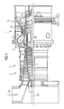
- Fig. 1 shows a partial longitudinal section through a stationary gas turbine trained turbine 1, which has a rotor 2, a compressor 3, a burner 4, an annular combustion chamber 5 with a combustion chamber 6 and a turbine part 7 having.
- the cooling air flow 11 is used to cool the Turbine part 7 and the rotor 3 used, whereas the Air mass flow 10 first for cooling the annular combustion chamber 5 and then used for combustion.
- the Air mass flow 10 after exiting the compressor 3 from a diffuser 12 in the direction of the annular combustion chamber 5 redirected and from there to burner 4.
- the burner 4 is then mixed Air mass flow 10 with a fuel, which is then in Combustion chamber 6 of the annular combustion chamber 5 is burned.
- the hot working medium 13 flows along a hot gas channel 14 past turbine stages 15.
- Each turbine stage 15 is thereby formed from two bucket rings connected in series. Seen in the flow direction of the working medium 13 follows a row of guide vanes formed from guide vanes 16 Row formed from blades 17. On the blades 17, which in contrast to those attached to the turbine housing 18 Guide vanes 16 are mounted on the rotor 2, this relaxes Working medium 13 pulse-like and thus drives one with the Rotor 2 connected generator, not shown, and the Compressor 3 on.
- the annular combustion chamber 5 follows radially inward ring channel 20 encompassing rotor 2.
- Fig. 2 shows a schematic longitudinal section through the Rotor 2, a compressor outlet 21, the diffuser 12, the Annular combustion chamber 5 and the first turbine stage 15 of the turbine 1.
- the annular combustion chamber 5 with the combustion chamber 6 is partially shown, in Fig. 2 above the diffuser 12.
- the combustion chamber 6 communicates with the hot gas duct 14, in which the guide and moving blades 16, 17 are arranged are.
- the compressor 3, not shown in FIG. 2, is the annular compressor outlet 21 fluidically connected downstream, which opens further downstream into the diffuser 12.
- the flow channel is divided in the diffuser 12 for the compressed air 9 by means of a flow wedge 24 in two sub-channels 23a, 23b (Y-type channel fork 22).
- the Flow wedge 24 surrounds the rotor 2 as a ring and is in the process connected to the diffuser 12 via a plurality of diffuser ribs 25; he is thus held firmly by them.
- Each subchannel 23a, 23b is therefore crossed by a plurality of diffuser ribs 25.
- the diffuser rib 25 is hollow, with a tube 26 runs through them.
- the tube 26 communicates on the one hand a water source, not shown, and on the other hand further connecting pipes with one at the end of the compressor of the annular channel 20 arranged nozzle 28.
- the ring channel 20 encircles the rotor 2 in an annular manner, wherein an inner wall 29 of the ring channel 20 spaced the rotor 2 embraces.
- the radially outer channel wall of the ring channel 20 is formed by an outer wall 30 leading to the inner wall 29 is spaced and in the axial direction of the rotor 2 extends.
- the outer wall 30 isolates the ring channel 20 thermally with respect to the ring combustion chamber 5.
- the ring channel 20 is thus ring-shaped around the rotor 2 and extends in the longitudinal direction parallel to this.
- the compressor compresses 3 the air drawn in by him, which then passes through the Compressor outlet 21 flows into the diffuser 12.
- a part of the air mass flow 10b flows into the cooling air extraction pipe 27 and is thus removed from this. This part will deflected so that it then into the ring channel 20th flows in and flows there as cooling air flow 11.
- the water flows from the water source through connecting pipes to tube 26 and from there to nozzle 28.
- the water is injected into the annular channel 20 and atomized into a large number of water pearls 31. This evaporate due to the sufficiently large volume of the Ring channel 20 completely in this, the surrounding heat is withdrawn, so that the cooling air flow 11 in the ring channel 20 is cooled.
- One due to high pressures in the compressor 3 hot cooling air flow 11 is so specified Temperature range cooled down.
- the amount of water injected is the temperature of the cooling air flow 11 adjustable.
- the cooling air flow 11 flows through the inner wall 29 the ring channel 20 and thereby convectively cools the rotor 2. In the annular gap between the fixed inner wall 29 and rotating rotor surface create air vortices that the Favor heat transfer from the rotor to the inner wall 29.
- the turbine-side end of the ring channel 20 then opens water droplet-free cooling air flow 11 into a in the rotor 2 located cooling duct system, which the cooling air flow 11th further to the guide vanes 16 and to the moving vanes 17 the first turbine stage 15 leads. These are then with the cooled cooling air stream 11 cooled without passing through Drops of water corrosion or thermal stresses are caused.
Landscapes
- Engineering & Computer Science (AREA)
- Mechanical Engineering (AREA)
- General Engineering & Computer Science (AREA)
- Chemical & Material Sciences (AREA)
- Combustion & Propulsion (AREA)
- Physics & Mathematics (AREA)
- Fluid Mechanics (AREA)
- Turbine Rotor Nozzle Sealing (AREA)
Abstract
Description
- Fig. 1
- einen Längsteilschnitt durch eine Gasturbine und
- Fig. 2
- einen schematischen Längsschnitt durch den Rotor, die Brennkammer, die erste Turbinenstufe und den Diffusor der Gasturbine gemäß Fig. 1.
Claims (12)
- Turbine (1), insbesondere eine Gasturbine, die entlang eines drehgelagerten rotationssymmetrischen Rotors (2) einen Verdichter (3), eine Brennkammer (5) und ein aus mehreren Turbinenstufen (15) gebildeten Turbinenteil (7) aufweist, bei der jede Turbinenstufe (15) miteinander zusammenwirkende Laufschaufeln (17) und Leitschaufeln (16) umfasst, die von einem heißen Arbeitsmedium (13) umströmbar sind,
mit einem von dem Verdichter (3) bereitgestellten Kühlmittel zur Kühlung der Schaufeln (16, 17), welches in einem Kanal entlang des Rotors (2) vom Verdichter (3) zum Turbinenteil (7) strömbar ist und in welches zur Kühlung eine Flüssigkeit einbringbar ist,
dadurch gekennzeichnet, dass der Kanal sich außerhalb der Rotors (2) erstreckt und dass die Flüssigkeit in einem verdichternahen Bereich in den Kanal einbringbar ist. - Turbine (1) nach Anspruch 1,
dadurch gekennzeichnet, dass der Kanal entlang des Rotors (2) verläuft und dieser vom Kühlmittel kühlbar ist. - Turbine (1) nach Anspruch 1 oder 2,
dadurch gekennzeichnet, dass der Kanal ein koaxial zum Rotor (2) ausgebildeter und von dem Kühlmittel durchströmter Ringkanal (20) ist, dessen der Brennkammer (5) zugewandte radial äußere Kanalwand (30) drehfest ist und den Kanal gegenüber der Brennkammer (5) thermisch isoliert. - Turbine (1) nach einem der Ansprüche 1 bis 3,
dadurch gekennzeichnet, dass die drehfeste innere Kanalwand zur Oberfläche des Rotors (2) beabstandet ist. - Turbine (1) nach einem der Ansprüche 1 bis 4,
dadurch gekennzeichnet, dass die Flüssigkeit in den Ringkanal (20) mittels einer Düse (28) einbringbar ist. - Turbine (1) nach einem der Ansprüche 1 bis 5,
dadurch gekennzeichnet, dass die Flüssigkeit Wasser, insbesondere destilliertes Wasser, ist. - Turbine (1) nach einem der Ansprüche 1 bis 6,
dadurch gekennzeichnet, dass das Kühlmittel Verdichteraustrittsluft ist. - Turbine (1) nach einem der Ansprüche 1 bis 7,
dadurch gekennzeichnet, dass in einem dem Verdichteraustritt in Strömungsrichtung der Verdichterluft nachgeschalteten Strömungskanal eine diesen durchquerende Diffusorrippe (25) angeordnet ist. - Turbine (1) nach Anspruch 9,
dadurch gekennzeichnet, dass das radial äußere Ende der Diffusorrippe (25) am Stator der Turbine (1) befestigt ist und das dem äußeren Ende gegenüberliegende radial innere Ende dem Rotor (2) zugewandt ist. - Turbine (1) nach einem der Ansprüche 1 bis 10,
dadurch gekennzeichnet, dass die Innenwand (29) und die äußere Kanalwand (30) mittels Stützrippen an einem Innengehäuse der Turbine (1) abgestützt sind. - Turbine (1) nach Anspruch 9, 10 oder 11,
dadurch gekennzeichnet, dass zumindest eine Rippe hohl ausgebildet ist und in ihr ein Rohr (26) verläuft, welches statorseitig mit einer Flüssigkeitsquelle und rotorseitig mit der zur Einbringung der Flüssigkeit im Ringkanal verwendeten Düse (28) kommuniziert. - Gasturbine mit einer Turbine (1) nach einem der vorhergehenden Ansprüche.
Priority Applications (1)
| Application Number | Priority Date | Filing Date | Title |
|---|---|---|---|
| EP20030020887 EP1418320B1 (de) | 2002-11-11 | 2003-09-15 | Gasturbine |
Applications Claiming Priority (3)
| Application Number | Priority Date | Filing Date | Title |
|---|---|---|---|
| EP02025194 | 2002-11-11 | ||
| EP20020025194 EP1418319A1 (de) | 2002-11-11 | 2002-11-11 | Gasturbine |
| EP20030020887 EP1418320B1 (de) | 2002-11-11 | 2003-09-15 | Gasturbine |
Publications (2)
| Publication Number | Publication Date |
|---|---|
| EP1418320A1 true EP1418320A1 (de) | 2004-05-12 |
| EP1418320B1 EP1418320B1 (de) | 2009-12-30 |
Family
ID=32109140
Family Applications (1)
| Application Number | Title | Priority Date | Filing Date |
|---|---|---|---|
| EP20030020887 Expired - Lifetime EP1418320B1 (de) | 2002-11-11 | 2003-09-15 | Gasturbine |
Country Status (1)
| Country | Link |
|---|---|
| EP (1) | EP1418320B1 (de) |
Cited By (2)
| Publication number | Priority date | Publication date | Assignee | Title |
|---|---|---|---|---|
| EP1640587A1 (de) * | 2004-09-22 | 2006-03-29 | Siemens Aktiengesellschaft | Kühlsystem für eine Gasturbine, Verdichterleitschaufel und Verfahren zum Kühlen einer Gasturbine |
| EP2003311A3 (de) * | 2007-06-13 | 2011-04-27 | United Technologies Corporation | Hybridkühlung eines Gasturbinenmotors |
Citations (3)
| Publication number | Priority date | Publication date | Assignee | Title |
|---|---|---|---|---|
| GB766883A (en) * | 1953-12-23 | 1957-01-30 | Rolls Royce | Improvements relating to gas turbines |
| DE2852057A1 (de) * | 1977-12-02 | 1979-06-07 | Hitachi Ltd | Verfahren und vorrichtung zum kuehlen einer gasturbinenschaufel |
| EP0379880A1 (de) * | 1989-01-27 | 1990-08-01 | Westinghouse Electric Corporation | Kühlungssystem und -methode für eine Gasturbine |
-
2003
- 2003-09-15 EP EP20030020887 patent/EP1418320B1/de not_active Expired - Lifetime
Patent Citations (3)
| Publication number | Priority date | Publication date | Assignee | Title |
|---|---|---|---|---|
| GB766883A (en) * | 1953-12-23 | 1957-01-30 | Rolls Royce | Improvements relating to gas turbines |
| DE2852057A1 (de) * | 1977-12-02 | 1979-06-07 | Hitachi Ltd | Verfahren und vorrichtung zum kuehlen einer gasturbinenschaufel |
| EP0379880A1 (de) * | 1989-01-27 | 1990-08-01 | Westinghouse Electric Corporation | Kühlungssystem und -methode für eine Gasturbine |
Cited By (5)
| Publication number | Priority date | Publication date | Assignee | Title |
|---|---|---|---|---|
| EP1640587A1 (de) * | 2004-09-22 | 2006-03-29 | Siemens Aktiengesellschaft | Kühlsystem für eine Gasturbine, Verdichterleitschaufel und Verfahren zum Kühlen einer Gasturbine |
| US7555892B2 (en) | 2004-09-22 | 2009-07-07 | Siemens Aktiengesellschaft | Cooling system for a gas turbine |
| EP2003311A3 (de) * | 2007-06-13 | 2011-04-27 | United Technologies Corporation | Hybridkühlung eines Gasturbinenmotors |
| US8056345B2 (en) | 2007-06-13 | 2011-11-15 | United Technologies Corporation | Hybrid cooling of a gas turbine engine |
| US8656722B2 (en) | 2007-06-13 | 2014-02-25 | United Technologies Corporation | Hybrid cooling of a gas turbine engine |
Also Published As
| Publication number | Publication date |
|---|---|
| EP1418320B1 (de) | 2009-12-30 |
Similar Documents
| Publication | Publication Date | Title |
|---|---|---|
| EP1418319A1 (de) | Gasturbine | |
| EP0991850B1 (de) | Turbinenwelle einer dampfturbine mit interner kühlung sowie verfahren zur kühlung einer turbinenwelle | |
| EP1443275B1 (de) | Brennkammer | |
| DE10303088B4 (de) | Abgasgehäuse einer Wärmekraftmaschine | |
| EP2430315B1 (de) | Strömungsvorrichtung mit kavitätenkühlung | |
| DE69018338T2 (de) | Gasturbine. | |
| DE60017396T2 (de) | Vorrichtung zur reduzierung der kühlung für einen turbineneinlasskanal | |
| DE60311197T2 (de) | Kühleinrichtung für eine Bürstendichtung | |
| DE3428892A1 (de) | Schaufel- und dichtspaltoptimierungseinrichtung fuer verdichter von gasturbinentriebwerken, insbesondere gasturbinenstrahltriebwerken | |
| EP1614859A1 (de) | Filmgekühlte Turbinenschaufel | |
| DE60124137T2 (de) | Aufeinanderfolgende doppelkühlung von brennkammerturbine | |
| EP1656497A1 (de) | Diffusor zwischen verdichter und brennkammer einer gasturbine angeordnet | |
| EP2084368A1 (de) | Turbinenschaufel | |
| WO2001009553A1 (de) | Prallkühlvorrichtung | |
| EP2823154B1 (de) | Kühlmittelüberbrückungsleitung, zugehörige turbinenschaufel, gasturbine und kraftwerksanlage | |
| EP1249578A1 (de) | Kühlung einer Gasturbine | |
| EP2206885A1 (de) | Gasturbine | |
| EP2098688A1 (de) | Gasturbine | |
| EP2347100B1 (de) | Gasturbine mit kühleinsatz | |
| EP1418320A1 (de) | Gasturbine | |
| EP3004741B1 (de) | Rohrbrennkammer mit einem flammrohr-endbereich und gasturbine | |
| EP1284391A1 (de) | Brennkammeranordnung für Gasturbinen | |
| EP2159377A1 (de) | Leitschaufelträger für eine Gasturbine und entsprechende Gasturbinenanlage | |
| EP1731715A1 (de) | Übergangsbereich zwischen einer Brennkammer und einer Turbineneinheit | |
| EP1676977A1 (de) | Gasturbine mit einem Vordrallerzeuger sowie Verfahren zum Betreiben einer Gasturbine |
Legal Events
| Date | Code | Title | Description |
|---|---|---|---|
| PUAI | Public reference made under article 153(3) epc to a published international application that has entered the european phase |
Free format text: ORIGINAL CODE: 0009012 |
|
| AK | Designated contracting states |
Kind code of ref document: A1 Designated state(s): AT BE BG CH CY CZ DE DK EE ES FI FR GB GR HU IE IT LI LU MC NL PT RO SE SI SK TR |
|
| AX | Request for extension of the european patent |
Extension state: AL LT LV MK |
|
| 17P | Request for examination filed |
Effective date: 20040819 |
|
| AKX | Designation fees paid |
Designated state(s): AT BE BG CH CY CZ DE DK EE ES FI FR GB GR HU IE IT LI LU MC NL PT RO SE SI SK TR |
|
| GRAP | Despatch of communication of intention to grant a patent |
Free format text: ORIGINAL CODE: EPIDOSNIGR1 |
|
| GRAS | Grant fee paid |
Free format text: ORIGINAL CODE: EPIDOSNIGR3 |
|
| GRAA | (expected) grant |
Free format text: ORIGINAL CODE: 0009210 |
|
| AK | Designated contracting states |
Kind code of ref document: B1 Designated state(s): AT BE BG CH CY CZ DE DK EE ES FI FR GB GR HU IE IT LI LU MC NL PT RO SE SI SK TR |
|
| REG | Reference to a national code |
Ref country code: GB Ref legal event code: FG4D Free format text: NOT ENGLISH |
|
| REG | Reference to a national code |
Ref country code: CH Ref legal event code: EP Ref country code: CH Ref legal event code: NV Representative=s name: SIEMENS SCHWEIZ AG |
|
| REG | Reference to a national code |
Ref country code: IE Ref legal event code: FG4D |
|
| REF | Corresponds to: |
Ref document number: 50312282 Country of ref document: DE Date of ref document: 20100211 Kind code of ref document: P |
|
| PG25 | Lapsed in a contracting state [announced via postgrant information from national office to epo] |
Ref country code: SE Free format text: LAPSE BECAUSE OF FAILURE TO SUBMIT A TRANSLATION OF THE DESCRIPTION OR TO PAY THE FEE WITHIN THE PRESCRIBED TIME-LIMIT Effective date: 20091230 Ref country code: FI Free format text: LAPSE BECAUSE OF FAILURE TO SUBMIT A TRANSLATION OF THE DESCRIPTION OR TO PAY THE FEE WITHIN THE PRESCRIBED TIME-LIMIT Effective date: 20091230 |
|
| REG | Reference to a national code |
Ref country code: NL Ref legal event code: VDEP Effective date: 20091230 |
|
| PG25 | Lapsed in a contracting state [announced via postgrant information from national office to epo] |
Ref country code: SI Free format text: LAPSE BECAUSE OF FAILURE TO SUBMIT A TRANSLATION OF THE DESCRIPTION OR TO PAY THE FEE WITHIN THE PRESCRIBED TIME-LIMIT Effective date: 20091230 |
|
| REG | Reference to a national code |
Ref country code: IE Ref legal event code: FD4D |
|
| PG25 | Lapsed in a contracting state [announced via postgrant information from national office to epo] |
Ref country code: BG Free format text: LAPSE BECAUSE OF FAILURE TO SUBMIT A TRANSLATION OF THE DESCRIPTION OR TO PAY THE FEE WITHIN THE PRESCRIBED TIME-LIMIT Effective date: 20100330 Ref country code: RO Free format text: LAPSE BECAUSE OF FAILURE TO SUBMIT A TRANSLATION OF THE DESCRIPTION OR TO PAY THE FEE WITHIN THE PRESCRIBED TIME-LIMIT Effective date: 20091230 Ref country code: EE Free format text: LAPSE BECAUSE OF FAILURE TO SUBMIT A TRANSLATION OF THE DESCRIPTION OR TO PAY THE FEE WITHIN THE PRESCRIBED TIME-LIMIT Effective date: 20091230 Ref country code: NL Free format text: LAPSE BECAUSE OF FAILURE TO SUBMIT A TRANSLATION OF THE DESCRIPTION OR TO PAY THE FEE WITHIN THE PRESCRIBED TIME-LIMIT Effective date: 20091230 Ref country code: PT Free format text: LAPSE BECAUSE OF FAILURE TO SUBMIT A TRANSLATION OF THE DESCRIPTION OR TO PAY THE FEE WITHIN THE PRESCRIBED TIME-LIMIT Effective date: 20100430 Ref country code: ES Free format text: LAPSE BECAUSE OF FAILURE TO SUBMIT A TRANSLATION OF THE DESCRIPTION OR TO PAY THE FEE WITHIN THE PRESCRIBED TIME-LIMIT Effective date: 20100410 |
|
| PG25 | Lapsed in a contracting state [announced via postgrant information from national office to epo] |
Ref country code: SK Free format text: LAPSE BECAUSE OF FAILURE TO SUBMIT A TRANSLATION OF THE DESCRIPTION OR TO PAY THE FEE WITHIN THE PRESCRIBED TIME-LIMIT Effective date: 20091230 Ref country code: CZ Free format text: LAPSE BECAUSE OF FAILURE TO SUBMIT A TRANSLATION OF THE DESCRIPTION OR TO PAY THE FEE WITHIN THE PRESCRIBED TIME-LIMIT Effective date: 20091230 |
|
| PG25 | Lapsed in a contracting state [announced via postgrant information from national office to epo] |
Ref country code: IE Free format text: LAPSE BECAUSE OF FAILURE TO SUBMIT A TRANSLATION OF THE DESCRIPTION OR TO PAY THE FEE WITHIN THE PRESCRIBED TIME-LIMIT Effective date: 20091230 Ref country code: GR Free format text: LAPSE BECAUSE OF FAILURE TO SUBMIT A TRANSLATION OF THE DESCRIPTION OR TO PAY THE FEE WITHIN THE PRESCRIBED TIME-LIMIT Effective date: 20100331 Ref country code: CY Free format text: LAPSE BECAUSE OF FAILURE TO SUBMIT A TRANSLATION OF THE DESCRIPTION OR TO PAY THE FEE WITHIN THE PRESCRIBED TIME-LIMIT Effective date: 20091230 |
|
| PLBE | No opposition filed within time limit |
Free format text: ORIGINAL CODE: 0009261 |
|
| STAA | Information on the status of an ep patent application or granted ep patent |
Free format text: STATUS: NO OPPOSITION FILED WITHIN TIME LIMIT |
|
| 26N | No opposition filed |
Effective date: 20101001 |
|
| PG25 | Lapsed in a contracting state [announced via postgrant information from national office to epo] |
Ref country code: DK Free format text: LAPSE BECAUSE OF FAILURE TO SUBMIT A TRANSLATION OF THE DESCRIPTION OR TO PAY THE FEE WITHIN THE PRESCRIBED TIME-LIMIT Effective date: 20091230 |
|
| BERE | Be: lapsed |
Owner name: SIEMENS A.G. Effective date: 20100930 |
|
| PG25 | Lapsed in a contracting state [announced via postgrant information from national office to epo] |
Ref country code: MC Free format text: LAPSE BECAUSE OF NON-PAYMENT OF DUE FEES Effective date: 20100930 |
|
| REG | Reference to a national code |
Ref country code: FR Ref legal event code: ST Effective date: 20110531 |
|
| PG25 | Lapsed in a contracting state [announced via postgrant information from national office to epo] |
Ref country code: FR Free format text: LAPSE BECAUSE OF NON-PAYMENT OF DUE FEES Effective date: 20100930 Ref country code: BE Free format text: LAPSE BECAUSE OF NON-PAYMENT OF DUE FEES Effective date: 20100930 |
|
| PG25 | Lapsed in a contracting state [announced via postgrant information from national office to epo] |
Ref country code: AT Free format text: LAPSE BECAUSE OF NON-PAYMENT OF DUE FEES Effective date: 20100915 |
|
| PG25 | Lapsed in a contracting state [announced via postgrant information from national office to epo] |
Ref country code: HU Free format text: LAPSE BECAUSE OF FAILURE TO SUBMIT A TRANSLATION OF THE DESCRIPTION OR TO PAY THE FEE WITHIN THE PRESCRIBED TIME-LIMIT Effective date: 20100701 Ref country code: LU Free format text: LAPSE BECAUSE OF NON-PAYMENT OF DUE FEES Effective date: 20100915 |
|
| PG25 | Lapsed in a contracting state [announced via postgrant information from national office to epo] |
Ref country code: TR Free format text: LAPSE BECAUSE OF FAILURE TO SUBMIT A TRANSLATION OF THE DESCRIPTION OR TO PAY THE FEE WITHIN THE PRESCRIBED TIME-LIMIT Effective date: 20091230 |
|
| PGFP | Annual fee paid to national office [announced via postgrant information from national office to epo] |
Ref country code: GB Payment date: 20150909 Year of fee payment: 13 |
|
| PGFP | Annual fee paid to national office [announced via postgrant information from national office to epo] |
Ref country code: IT Payment date: 20150924 Year of fee payment: 13 |
|
| PGFP | Annual fee paid to national office [announced via postgrant information from national office to epo] |
Ref country code: CH Payment date: 20151202 Year of fee payment: 13 Ref country code: DE Payment date: 20151120 Year of fee payment: 13 |
|
| REG | Reference to a national code |
Ref country code: DE Ref legal event code: R119 Ref document number: 50312282 Country of ref document: DE |
|
| REG | Reference to a national code |
Ref country code: CH Ref legal event code: PL |
|
| GBPC | Gb: european patent ceased through non-payment of renewal fee |
Effective date: 20160915 |
|
| PG25 | Lapsed in a contracting state [announced via postgrant information from national office to epo] |
Ref country code: DE Free format text: LAPSE BECAUSE OF NON-PAYMENT OF DUE FEES Effective date: 20170401 Ref country code: CH Free format text: LAPSE BECAUSE OF NON-PAYMENT OF DUE FEES Effective date: 20160930 Ref country code: LI Free format text: LAPSE BECAUSE OF NON-PAYMENT OF DUE FEES Effective date: 20160930 Ref country code: GB Free format text: LAPSE BECAUSE OF NON-PAYMENT OF DUE FEES Effective date: 20160915 |
|
| PG25 | Lapsed in a contracting state [announced via postgrant information from national office to epo] |
Ref country code: IT Free format text: LAPSE BECAUSE OF NON-PAYMENT OF DUE FEES Effective date: 20160915 |