EP1418117A2 - Locking device and vehicle comprising a locking device - Google Patents
Locking device and vehicle comprising a locking device Download PDFInfo
- Publication number
- EP1418117A2 EP1418117A2 EP03025484A EP03025484A EP1418117A2 EP 1418117 A2 EP1418117 A2 EP 1418117A2 EP 03025484 A EP03025484 A EP 03025484A EP 03025484 A EP03025484 A EP 03025484A EP 1418117 A2 EP1418117 A2 EP 1418117A2
- Authority
- EP
- European Patent Office
- Prior art keywords
- locking
- cover
- locking device
- locking member
- pivot shafts
- Prior art date
- Legal status (The legal status is an assumption and is not a legal conclusion. Google has not performed a legal analysis and makes no representation as to the accuracy of the status listed.)
- Granted
Links
Images



Classifications
-
- B—PERFORMING OPERATIONS; TRANSPORTING
- B62—LAND VEHICLES FOR TRAVELLING OTHERWISE THAN ON RAILS
- B62K—CYCLES; CYCLE FRAMES; CYCLE STEERING DEVICES; RIDER-OPERATED TERMINAL CONTROLS SPECIALLY ADAPTED FOR CYCLES; CYCLE AXLE SUSPENSIONS; CYCLE SIDECARS, FORECARS, OR THE LIKE
- B62K19/00—Cycle frames
- B62K19/46—Luggage carriers forming part of frame
-
- B—PERFORMING OPERATIONS; TRANSPORTING
- B62—LAND VEHICLES FOR TRAVELLING OTHERWISE THAN ON RAILS
- B62H—CYCLE STANDS; SUPPORTS OR HOLDERS FOR PARKING OR STORING CYCLES; APPLIANCES PREVENTING OR INDICATING UNAUTHORIZED USE OR THEFT OF CYCLES; LOCKS INTEGRAL WITH CYCLES; DEVICES FOR LEARNING TO RIDE CYCLES
- B62H5/00—Appliances preventing or indicating unauthorised use or theft of cycles; Locks integral with cycles
- B62H5/006—Appliances preventing or indicating unauthorised use or theft of cycles; Locks integral with cycles acting on the saddle
Definitions
- the invention relates to a locking device, in particular for a cover of a saddle type vehicle, comprising a pair of left and right pivot shafts, a pair of left and right locking plates mounted for rotation with said pivot shafts, a pair of left and right strikers for engagement and disengagement with said locking plates, respectively, and a locking member for releasably locking said engagements.
- a saddle type vehicle comprising a container case supported on a body and a cover for openably closing an opening of said container case.
- Such a locking device as it may be applied to a cover in a saddle type vehicle, wherein the cover is provided for openably closing an opening of a container case supported on a body, and this cover is locked in the body, as well as a saddle type vehicle comprising such a locking device, is known, for example, from JPC 3100682.
- a container case is supported on a body having a cover for openably closing the opening of this container case, and comprising: a pair of left and right pivot shafts supported on the body by support brackets, a pair of left and right locking plates mounted for rotation to the body by these pivot shafts, a pair of left and right strikers supported on the cover and engaged with the locking plates for disengagement, respectively, a pair of left and right springs for biasing these locking plates so as to release the engaging states of the locking plates with the strikers, and a pair of left and right locking members for releasably locking the engagements, respectively.
- the strikers are engaged separately by the locking plates and these two engagements are locked separately by the locking members.
- the operator is not able to recognize visually whether or not each of the two engagements is locked, so that it is to be confirmed tactually or aurally.
- the biasing force might unfavorably cause the gap to be widened.
- an object of the invention to provide a more reliable locking, device also having a simplified structure and a saddle type vehicle comprising such a locking device.
- this object is solved in an inventive manner by a locking device for locking said cover in a closed state according to at least one of the claims 1 to 6.
- said locking member is provided only to one locking plate of said left and right locking plates, the number of parts is decreased compared with the prior art in which locking members are provided to the left and right locking plates, respectively, and the construction of the locking device is simplified in this respect.
- the container case and the cover are arranged such that no gap is produced in joint portions of the opening of the container case and the cover through locking of the engagements by only the locking member, the gap in the joint portions of the opening of the container case and the cover is prevented from being produced, and ingress of rain water into the container case is also prevented provided that only completion of locking of the engagements by the locking member alone is recognized.
- a spring is provided for biasing said one locking plate to release said engagements.
- the locking device comprises a key-operated type main switch being connected to said locking member.
- a sensor is provided for detecting said engagements, and this sensor is provided to the other locking plate of said left and right locking plates.
- the saddle type vehicle comprises a container case supported on a body, a cover for openably closing an opening of said container case, a pair of left and right pivot shafts supported on said body by support brackets.
- a pair of left and right locking plates are mounted for rotation to the body by said pivot shafts.
- a pair of left and right strikers are supported on said cover.
- said support brackets, pivot shafts and locking plates are preferably connected together as an assembly, and this assembly is attached to the body in one unit.
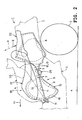
- reference numeral 1 designates a saddle type vehicle of a scooter type and an arrow Fr shows the front of this vehicle 1.
- Terms of left and right in the following description mean lateral directions of a body 2 of the vehicle 1 as seen toward the front.
- the vehicle 1 comprises the body 2, an unillustrated front wheel supported for steering movement at the front of the body 2, and a rear wheel 3 supported at the rear of the body 2 by an unillustrated drive unit.
- the body 2 is supported by these wheels 3 on the running surface 4.
- the body 2 comprises a body frame 6 constituting its frame, side panels 7 supported on the body frame 6.
- the body frame 6 comprises a pair of longitudinally extending left and right main frames 6a, 6a, and a cross member 6b extending in the lateral direction of the body 2 for connecting the main frames 6a, 6a to each other.
- the vehicle 1 comprises a container device 9 for holding small items 8 such as a helmet.
- the container device 9, which is supported on the body frame 6 of the body 2, comprises an upwardly opening plastic container case 10, a plastic cover 12 for openably closing the opening 11 of the container case 10 at its upper end from above, an elastic sealing member 13 supported on the cover 12 and held between the opening edge of the opening 11 of the container case 10 and the cover 12 for sealing their joint portions, and a hinge 14 for pivotally mounting the forward end of the cover 12 to the forward end of the container case 10 on the body 2 such that the rear of the cover 12 makes forward and backward rotational movements A, B upwardly toward the front.
- a closed space surrounded by the container case 10 and the cover12 constitutes a container space 15 for the small items 8.
- the vehicle 1 comprises a riders seat 18 supported on the body 2 and taking a posture for sitting-on.
- the seat 18 comprises a seat frame 19 constituted by the cover 12, and a seat pad 20 supported on the seat frame 19.
- the front of the seat 18 is used as a main seat 21 for a driver, and the rear of the seat 18 as a tandem seat 22 for a tandem rider.
- the vehicle 1 comprises a locking device 25 capable of locking the cover 12 which has closed the opening 11. of the container case 10 while the cover is taking the closing posture, and capable of locking the seat 18 while the seat is taking a posture for sitting-on.
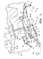
- the locking device 25 comprises a pair of left and right support brackets 27, 27 disposed downwardly of the longitudinal middle (approximately a central portion) of the container case 10 and supported on the underside of the cross member 6b of the body frame 6 through fastening of fastening members 26, and a pair of left and right pivot shafts 29, 29 disposed on a common axial center 28 extending in the lateral direction of the body 2 and supported on the support brackets 27, 27 for rotation about the axial center 28.
- Each support bracket 27 comprises a plastic bracket body 31 supported on the cross member 6b of the body frame 6 with the fastening members 26 for supporting the lower side of the pivot shaft 29 from below, and a sheet metal shaft pusher 33 fastened to the bracket body 31 with a fastening member 32 for pushing the upper side of the pivot shaft 29 from above.
- the shaft pusher 33 is formed with a bead 34 bulging radially outwardly of the pivot shaft 29 and extending around the periphery of the pivot shaft 29.
- the inside of the bead 34 is filled with grease for lubricating the sliding portion of the pivot shaft 29 with the support bracket 27, or lubricating oil 35.
- the locking device 25 comprises a pair of left and right locking plates 38, 38 fixed to the pivot shafts 29 by welding and protruding rearward from the pivot shafts 29, respectively.
- Each locking plate 38 has an engagement cutout 39 extending from the protruding end toward the base thereof.
- the locking plates 38, 38 make forward and backward rotational movement C, D around the axial center 28 together with the pivot shafts 29 upwardly toward the front.
- the locking device 25 comprises a pair of left and right strikers 40, 40 supported on the cover 12, protruding downward from the cover 12 and engaged for disengagement with their respective engagement cutouts 39 of the locking plates 38 moved in a returning rotational direction of D, as shown in Figs.
- a spring 41 for elastically biasing the locking plate 38 such that the locking plate 38 is moved in the forward rotational direction of C to release the engagement, as shown in Figs. 1 and 5 by single dot and dash lines; and a locking member 42 for releasably locking the engagement against the spring force of the spring 41.
- the left and right pivot shafts 29, 29 are formed integral with each other into a single shaft.
- the locking member 42 is provided to only one of the left and right locking plates 38, 38, or the right locking plate 38(R).
- the spring 41 is provided to directly bias the right locking plate.38(R) only.
- the locking member 42 comprises a locking member body 45 supported in the right support bracket 27 for a back-and-forth sliding movement in a forward and/or returning direction with an engagement portion 44 formed in the right locking plate 38(R) and engaged with the engagement portion 44 for disengagement through the sliding movement, for locking the locking plate 38 while the locking plate is taking a posture of returning rotational movement D, as shown in Figs. 1 and 3-5 by solid lines; and a spring 46 for elastically biasing the locking member body 45 such that the locking member body 45 is engaged with the engagement portion 44.
- a key-operated type main switch 48 which is supported on the body 2.
- To the main switch 48 is connected, in association therewith, the locking member body 45 of the locking member 42 by a cable 49 which extends in the longitudinal direction approximately in a straight line in plan view of the body 2.
- the locking member body 45 of the locking member 42 is moved in association with the main switch 48 and engagement of the locking member body 45 with the engagement portion 44 of the locking plate 38(R) is released. In other words, locking of the engagement of the striker 40 with the locking plate 38(R) is released.
- the locking plate 38 is biased by the spring 41 such that it makes a forward rotational movement C. That is, the locking plate is biased by the spring 41 such that engagement of the striker 40 with the locking plate 38 is released. This allows the forward rotational movement A of the cover 12 (seat 18).
- the opening 11 of the container case 10 is opened, allowing small items 8 to be put into or taken out from the container case 10.
- the right striker 40 begins to engage with the engagement cutout 39 of the right locking plate 38(R), as shown in Fig. 1 by a single dot and dash line. If the cover 12 (seat 18) is rotated further in the returning rotational direction of B, the striker 40 is engaged with the locking plate 38, as shown in Figs. 1 and 3-5 by solid lines, and the biasing force of the spring 46 causes the locking member body 45 to be engaged with the engagement portion 44 of the locking plate 38(R), so that the engagement is locked as it is and the locking device 25 returns to the original state.
- a sensor 51 supported on the support bracket 27 for detecting the engagement, and a lamp 52 connected to the sensor 51 for illuminating the container space 15.
- the lamp 52 is turned off through detection of the engagement by the sensor 51 and it is turned on through detection of the engagement being released. Putting-in and taking-out of the small items 8 to and from the container case 10 is thereby facilitated.
- the sensor 51 is provided to the other of the two locking plates 38, 38, or the left locking plate 38(L).
- the support brackets 27, 27, pivot shafts 29, 29, left and right locking plates 38, 38, locking member 42 and sensor 51 are connected together by connecting members 53 and the like into an assembly 54.
- the assembly 54 can be removably attached to the cross member 6b of the body frame 6 of the body 2 with the fastening members 26.
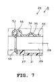
- the connecting member 53 comprises a snap ring 55 removably fitted on the pivot shaft 29 near the side of the shaft pusher 33, and a connecting piece 56 protruding from the shaft pusher 33 integral therewith and extending to a region near the side of the snap ring 55 opposite the shaft pusher 33.
- Fig. 8 shows another embodiment of the connecting member 53.
- the connecting member 53 comprises a connecting piece 59 protruded from the shaft pusher 33 integral therewith and having a fitting hole 58 for the snap ring 55 partially to be fitted in.
- the construction is the same as the foregoing connecting member 53, so that like parts in the figure are designated by like reference numerals and the description is omitted.
- the left and right pivot shafts 29, 29 are formed integral with each other.
- the locking member 42 is provided to only one locking plate 38(R) of the left and right locking plates 38, 38.
- the container case 10 and the cover 12 are arranged such that no gap is produced in joint portions of the opening 11 of the container case 10 and the cover 12 through locking of the engagements by only the locking member 42, the gap in the joint portions of the opening 11 of the container case 10 and the cover 12 is prevented from being produced provided that only completion of locking of the engagements by the locking member 42 alone is recognized.
- a spring 41 is provided for biasing said one locking plate 38(R) to release the engagements.
- a key-operated type main switch 48 is disposed laterally on one side of the body 2, to the main switch 48 is connected in association therewith the locking member 42, and the locking member 42 is disposed laterally on the same side as said one side of the body 2.
- a sensor 51 for detecting engagements is provided, and the sensor 51 is provided to the other locking plate 38(L) of the left and right locking plates 38,38.
- the support brackets 27, pivot shafts 29, locking plates 38, locking member 42 and sensor 51 are connected together as an assembly 54 and the assembly 54 can be attached to the body 2 in one unit.
- the support brackets 27, pivot shafts 29, locking plates 38, locking member 42 and sensor 51 are covered from above approximately entirely by a cross member 6b of the body frame 6 of the body 2, and the container case 10 is disposed upwardly of the cross member 6b.
- the support brackets 27, 27 and the like are protected by the cross member 6b, and assembling work of the support brackets 27, 27 and the like to the body 2 can be performed easily without interference with the container case 10.
- one of the two locking plates 38, 38 may be the locking plate on the left side.
- the sensor 51 may be one for theft prevention.
- a locking device preferably for a cover in a saddle type vehicle comprising a container case supported on a body, a cover for openably closing an opening of said container case, a pair of left and right pivot shafts supported on said body by support brackets, a pair of left and right locking plates mounted for rotation to the body by said pivot shafts, a pair of left and right strikers supported on said cover and engaged for disengagement with said locking plates, respectively, and a locking member for releasably locking said engagements, wherein said left and right pivot shafts are formed integral with each other.
- said locking member is provided only to one locking plate of said left and right locking plates.
- the container case and the cover are arranged such that no gap is produced in joint portions of the opening of the container case and the cover through locking of the engagements by only the locking member, the gap in the joint portions of the opening of the container case and the cover is prevented from being produced, and ingress of rain water into the container case is also prevented provided that only completion of locking of the engagements by the locking member alone is recognized.
- the locking device for a cover in a saddle type vehicle is provided with a spring for biasing said one locking plate to release said engagements.
- a further embodiment is directed to a locking device for a cover in a saddle type vehicle, wherein laterally on one side of the body is disposed a key-operated type main switch, to this main switch is connected said locking member in association therewith, and this locking member is disposed laterally on the same side as said one side of the body.
- the locking member and the main switch are disposed on the same side of the body, these locking member and main switch come closer to each other, so that the construction of connecting means such as a cable for connecting these locking member and main switch to each other in associated relation, is simplified. In other words, the construction of the locking device is simplified.
- a sensor is provided for detecting said engagements, and this sensor is provided to the other locking plate of said left and right locking plates.
- said support brackets, pivot shafts and locking plates are connected together as an assembly, and this assembly is attached to the body in one unit.
- the support brackets, pivot shafts and locking plates are assembled together into an assembly in advance in a wide working space and the assembly is assembled to the body after verification of the function, such as rotational movement, of the pivot shaft in the assembly, the assembling work can be facilitated to a great extent compared with when the support brackets, pivot shafts and locking plates are assembled separately to the body.
- the left and right pivot shafts 29, 29 are formed integral with each other.
- the locking member 42 is provided only to one locking plate 38(R) of the left and right locking plates 38, 38.
Landscapes
- Engineering & Computer Science (AREA)
- Mechanical Engineering (AREA)
- Lock And Its Accessories (AREA)
- Sampling And Sample Adjustment (AREA)
- Snaps, Bayonet Connections, Set Pins, And Snap Rings (AREA)
Abstract
Description
- Fig. 1
- is a sectional view as seen along the arrows of the line 1-1 of Fig. 3;
- Fig. 2
- is a side view of the rear of a vehicle;
- Fig. 3
- is a plan view as seen along the arrows of the line 3-3 of Fig. 2;
- Fig. 4
- is a sectional view as seen along the arrows of the line 4-4 of Fig. 3;
- Fig. 5
- is a sectional view as seen along the arrows of the line 5-5 of Fig. 3;
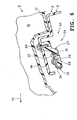
- Fig. 6
- is a sectional view as seen along the arrows of the
line 6―6 of Fig. 3; - Fig. 7
- is an enlarged sectional view of the section "7" of Fig. 4; and
- Fig. 8
- is a view of another embodiment corresponding to Fig. 7.
Claims (11)
- Locking device, in particular for a cover of a saddle type vehicle (1), comprising a pair of left and right pivot shafts (29,29), a pair of left and right locking plates (38,38) mounted for rotation with said pivot shafts (29,29), a pair of left and right strikers (40,40) for engagement and disengagement with said locking plates (38,38), respectively, and a locking member (42) for releasably locking said engagements,
characterized in that
said left and right pivot shafts (29,29) are formed integrally with each other. - Locking device according to claim 1, characterized in that said locking member (42) is provided only at one (38(R)) of said left and right locking plates (38,38).
- Locking device according to claim 2, characterized in that a spring (41) is provided for biasing said one locking plate (38(R)) to release said engagements.
- Locking device according to at least one of the claims 1 to 3, characterized by further comprising a key-operated type main switch (48) being connected to said one locking member (42).
- Locking device according to at least one of the claims 1 to 4, characterized in that a sensor (51) is provided for detecting said engagements.
- Locking device according to claim 5, characterized in that said sensor (51) is provided to the other locking plate (38(L)) of said left and right locking plates (38,38).
- Saddle type vehicle comprising a container case (10) supported on a body (2) and a cover (12) for openably closing an opening (11) of said container case (10), characterized by a locking device (25) for locking said cover (12) in a closed state according to at least one of the claims 1 to 6.
- Saddle type vehicle according to claim 7, characterized in that said pair of left and right pivot shafts (29,29) are supported on said vehicle body (2) by support brackets (27).
- Saddle type vehicle according to claim 7 or 8, characterized in that said pair of left and right strikers (40,40) are supported on said cover (12).
- Saddle type vehicle according to at least one of the claims 7 to 9, characterized in that said support brackets (27), pivot shafts (29) and locking plates (38) are connected together as an assembly (54), wherein this assembly (54) is attached to the body (2) of the vehicle (1) in one unit.
- Saddle type vehicle according to at least one of the claims 7 to 10, characterized in that the key-operated type main switch (48) is disposed laterally on one side of the vehicle body (2), this main switch (48) being connected to said locking member (42) in association therewith, and wherein this locking member (42) is disposed laterally on the same side as said one side of the body (2).
Applications Claiming Priority (2)
| Application Number | Priority Date | Filing Date | Title |
|---|---|---|---|
| JP2002326069A JP4229429B2 (en) | 2002-11-08 | 2002-11-08 | Lock device for cover in saddle riding type vehicle |
| JP2002326069 | 2002-11-08 |
Publications (3)
| Publication Number | Publication Date |
|---|---|
| EP1418117A2 true EP1418117A2 (en) | 2004-05-12 |
| EP1418117A3 EP1418117A3 (en) | 2007-05-02 |
| EP1418117B1 EP1418117B1 (en) | 2010-08-04 |
Family
ID=32105513
Family Applications (1)
| Application Number | Title | Priority Date | Filing Date |
|---|---|---|---|
| EP20030025484 Expired - Lifetime EP1418117B1 (en) | 2002-11-08 | 2003-11-06 | Locking device and vehicle comprising a locking device |
Country Status (6)
| Country | Link |
|---|---|
| EP (1) | EP1418117B1 (en) |
| JP (1) | JP4229429B2 (en) |
| CN (1) | CN1305727C (en) |
| DE (1) | DE60333619D1 (en) |
| ES (1) | ES2347988T3 (en) |
| TW (1) | TWI232825B (en) |
Cited By (4)
| Publication number | Priority date | Publication date | Assignee | Title |
|---|---|---|---|---|
| EP1864895A1 (en) | 2006-06-09 | 2007-12-12 | Yamaha Hatsudoki Kabushiki Kaisha | Motorcycle |
| WO2009113103A1 (en) * | 2008-02-22 | 2009-09-17 | Tvs Motor Company Limited | Anti-theft device for a two wheeled vehicles |
| CN103448840A (en) * | 2012-05-31 | 2013-12-18 | 雅马哈发动机株式会社 | Saddle type vehicle |
| WO2019064478A1 (en) * | 2017-09-29 | 2019-04-04 | 本田技研工業株式会社 | Saddle-type electric vehicle |
Families Citing this family (3)
| Publication number | Priority date | Publication date | Assignee | Title |
|---|---|---|---|---|
| JP4673654B2 (en) * | 2005-03-31 | 2011-04-20 | 本田技研工業株式会社 | Side trunk locking device for motorcycles |
| DE102016209092A1 (en) * | 2016-05-25 | 2017-11-30 | Bayerische Motoren Werke Aktiengesellschaft | Locking device for a seat of a motorcycle |
| CN108945189B (en) * | 2018-07-10 | 2020-09-04 | 浙江自然啄木鸟鞋业有限公司 | A convenient motorcycle seat lock |
Family Cites Families (6)
| Publication number | Priority date | Publication date | Assignee | Title |
|---|---|---|---|---|
| JPS55148669A (en) * | 1979-05-10 | 1980-11-19 | Yamaha Motor Co Ltd | Locking device for sheet of autobicycle |
| JPS6067279A (en) * | 1983-09-26 | 1985-04-17 | ヤマハ発動機株式会社 | Seat locking device for saddling type car |
| US5020625A (en) * | 1988-09-06 | 1991-06-04 | Suzuki Jidosha Kogyo Kabushiki Kaisha | Motor bicycle provided with article accommodating apparatus |
| US5127560A (en) * | 1990-01-25 | 1992-07-07 | Suzuki Kabushiki Kaisha | Storage box with openable lid for a motorcycle |
| JP3100682B2 (en) * | 1991-07-04 | 2000-10-16 | 本田技研工業株式会社 | Motorcycle seat lock device |
| JP3382489B2 (en) * | 1997-01-21 | 2003-03-04 | 本田技研工業株式会社 | Seat mounting structure for scooter type vehicle |
-
2002
- 2002-11-08 JP JP2002326069A patent/JP4229429B2/en not_active Expired - Fee Related
-
2003
- 2003-10-31 TW TW92130474A patent/TWI232825B/en not_active IP Right Cessation
- 2003-11-06 ES ES03025484T patent/ES2347988T3/en not_active Expired - Lifetime
- 2003-11-06 DE DE60333619T patent/DE60333619D1/en not_active Expired - Lifetime
- 2003-11-06 EP EP20030025484 patent/EP1418117B1/en not_active Expired - Lifetime
- 2003-11-07 CN CNB2003101148614A patent/CN1305727C/en not_active Expired - Fee Related
Cited By (7)
| Publication number | Priority date | Publication date | Assignee | Title |
|---|---|---|---|---|
| EP1864895A1 (en) | 2006-06-09 | 2007-12-12 | Yamaha Hatsudoki Kabushiki Kaisha | Motorcycle |
| WO2009113103A1 (en) * | 2008-02-22 | 2009-09-17 | Tvs Motor Company Limited | Anti-theft device for a two wheeled vehicles |
| CN103448840A (en) * | 2012-05-31 | 2013-12-18 | 雅马哈发动机株式会社 | Saddle type vehicle |
| CN103448840B (en) * | 2012-05-31 | 2016-04-27 | 雅马哈发动机株式会社 | Straddle riding type vehicle |
| WO2019064478A1 (en) * | 2017-09-29 | 2019-04-04 | 本田技研工業株式会社 | Saddle-type electric vehicle |
| WO2019065898A1 (en) * | 2017-09-29 | 2019-04-04 | 本田技研工業株式会社 | Saddle-type electric vehicle |
| US11420698B2 (en) | 2017-09-29 | 2022-08-23 | Honda Motor Co., Ltd. | Saddle type electric vehicle |
Also Published As
| Publication number | Publication date |
|---|---|
| JP2004161032A (en) | 2004-06-10 |
| TW200413209A (en) | 2004-08-01 |
| TWI232825B (en) | 2005-05-21 |
| EP1418117B1 (en) | 2010-08-04 |
| CN1532108A (en) | 2004-09-29 |
| CN1305727C (en) | 2007-03-21 |
| DE60333619D1 (en) | 2010-09-16 |
| ES2347988T3 (en) | 2010-11-26 |
| JP4229429B2 (en) | 2009-02-25 |
| EP1418117A3 (en) | 2007-05-02 |
Similar Documents
| Publication | Publication Date | Title |
|---|---|---|
| EP1422133B1 (en) | Scooter type vehicle | |
| JP5091804B2 (en) | Saddle bag mounting structure for motorcycles | |
| JP4119344B2 (en) | Motorcycle | |
| AU2007322725B2 (en) | Installation structure for door guard bar | |
| JP4243162B2 (en) | non-motorized vehicle | |
| EP1418117B1 (en) | Locking device and vehicle comprising a locking device | |
| EP1679254B1 (en) | Motorcycle comprising a swing arm supporting structure | |
| US7571952B1 (en) | Protection screen and truck equipped with it | |
| EP2030879B1 (en) | A seat assembly for a motorcycle and a motorcycle equipped with such a seat assembly | |
| US7823946B2 (en) | Lid device and glove box device for vehicle equipped with it | |
| CN102398645B (en) | Seat hinge structure | |
| CN110446652A (en) | Seat hinge structure of straddle vehicle | |
| JPWO2018159014A1 (en) | Meter mounting structure for saddle-ride type vehicles | |
| US11772735B2 (en) | Main step structure for saddle riding vehicle | |
| EP3971067A1 (en) | Straddled vehicle seat lock | |
| JP5030900B2 (en) | Small vehicle loading structure | |
| JP4574381B2 (en) | Step structure for motorcycle driver | |
| KR100763869B1 (en) | Body structure of motorcycle | |
| JP2017190012A (en) | Frame structure of saddle riding type vehicle | |
| JP4225045B2 (en) | License plate mounting structure | |
| CN101386326B (en) | Motorcycle | |
| JP2007314021A (en) | Seal mounting structure for vehicles and motorcycles | |
| JP5480611B2 (en) | Work vehicle | |
| JP3991631B2 (en) | Saddle-type vehicle storage container | |
| JP2011148453A (en) | Front structure of saddle-riding type vehicle |
Legal Events
| Date | Code | Title | Description |
|---|---|---|---|
| PUAI | Public reference made under article 153(3) epc to a published international application that has entered the european phase |
Free format text: ORIGINAL CODE: 0009012 |
|
| AK | Designated contracting states |
Kind code of ref document: A2 Designated state(s): AT BE BG CH CY CZ DE DK EE ES FI FR GB GR HU IE IT LI LU MC NL PT RO SE SI SK TR |
|
| AX | Request for extension of the european patent |
Extension state: AL LT LV MK |
|
| PUAL | Search report despatched |
Free format text: ORIGINAL CODE: 0009013 |
|
| AK | Designated contracting states |
Kind code of ref document: A3 Designated state(s): AT BE BG CH CY CZ DE DK EE ES FI FR GB GR HU IE IT LI LU MC NL PT RO SE SI SK TR |
|
| AX | Request for extension of the european patent |
Extension state: AL LT LV MK |
|
| RIC1 | Information provided on ipc code assigned before grant |
Ipc: B62J 1/12 20060101ALI20070328BHEP Ipc: B62H 5/00 20060101AFI20070328BHEP Ipc: B62K 19/46 20060101ALI20070328BHEP |
|
| 17P | Request for examination filed |
Effective date: 20070411 |
|
| 17Q | First examination report despatched |
Effective date: 20071127 |
|
| AKX | Designation fees paid |
Designated state(s): DE ES FR GB IT |
|
| GRAP | Despatch of communication of intention to grant a patent |
Free format text: ORIGINAL CODE: EPIDOSNIGR1 |
|
| GRAS | Grant fee paid |
Free format text: ORIGINAL CODE: EPIDOSNIGR3 |
|
| GRAA | (expected) grant |
Free format text: ORIGINAL CODE: 0009210 |
|
| AK | Designated contracting states |
Kind code of ref document: B1 Designated state(s): DE ES FR GB IT |
|
| REG | Reference to a national code |
Ref country code: GB Ref legal event code: FG4D |
|
| REF | Corresponds to: |
Ref document number: 60333619 Country of ref document: DE Date of ref document: 20100916 Kind code of ref document: P |
|
| PLBE | No opposition filed within time limit |
Free format text: ORIGINAL CODE: 0009261 |
|
| STAA | Information on the status of an ep patent application or granted ep patent |
Free format text: STATUS: NO OPPOSITION FILED WITHIN TIME LIMIT |
|
| 26N | No opposition filed |
Effective date: 20110506 |
|
| REG | Reference to a national code |
Ref country code: DE Ref legal event code: R097 Ref document number: 60333619 Country of ref document: DE Effective date: 20110506 |
|
| REG | Reference to a national code |
Ref country code: FR Ref legal event code: PLFP Year of fee payment: 13 |
|
| REG | Reference to a national code |
Ref country code: FR Ref legal event code: PLFP Year of fee payment: 14 |
|
| REG | Reference to a national code |
Ref country code: FR Ref legal event code: PLFP Year of fee payment: 15 |
|
| PGFP | Annual fee paid to national office [announced via postgrant information from national office to epo] |
Ref country code: DE Payment date: 20191121 Year of fee payment: 17 |
|
| PGFP | Annual fee paid to national office [announced via postgrant information from national office to epo] |
Ref country code: FR Payment date: 20191120 Year of fee payment: 17 Ref country code: ES Payment date: 20191220 Year of fee payment: 17 Ref country code: IT Payment date: 20191128 Year of fee payment: 17 |
|
| PGFP | Annual fee paid to national office [announced via postgrant information from national office to epo] |
Ref country code: GB Payment date: 20191120 Year of fee payment: 17 |
|
| REG | Reference to a national code |
Ref country code: DE Ref legal event code: R119 Ref document number: 60333619 Country of ref document: DE |
|
| GBPC | Gb: european patent ceased through non-payment of renewal fee |
Effective date: 20201106 |
|
| PG25 | Lapsed in a contracting state [announced via postgrant information from national office to epo] |
Ref country code: IT Free format text: LAPSE BECAUSE OF NON-PAYMENT OF DUE FEES Effective date: 20201106 Ref country code: FR Free format text: LAPSE BECAUSE OF NON-PAYMENT OF DUE FEES Effective date: 20201130 |
|
| PG25 | Lapsed in a contracting state [announced via postgrant information from national office to epo] |
Ref country code: GB Free format text: LAPSE BECAUSE OF NON-PAYMENT OF DUE FEES Effective date: 20201106 Ref country code: DE Free format text: LAPSE BECAUSE OF NON-PAYMENT OF DUE FEES Effective date: 20210601 |
|
| REG | Reference to a national code |
Ref country code: ES Ref legal event code: FD2A Effective date: 20220131 |
|
| PG25 | Lapsed in a contracting state [announced via postgrant information from national office to epo] |
Ref country code: ES Free format text: LAPSE BECAUSE OF NON-PAYMENT OF DUE FEES Effective date: 20201107 |